1-4101-EN SKF Grease injection system Grease injecting lubrication system type GVP for moving conveyor chain pins and rollers The grease injecting lubrication system GVP has been developed to lubricate conveyor chains fitted with grease nipples. The lubrica- tion process is automatically performed while the chain keeps moving. There is no produc- tion slow down. The lubricant is injected under pressure directly into the chain pins and/or rollers. The injected volumetric metered quantity of lubricant is adjustable. It remains independent from lubricant viscosity and from any back pressure due to the pin or roller type. There is a large range of conveyor chains and and different operating conditions. Therefore, the GVP unit is often the result of a close collaboration – development, installation, commissioning – between the user and SKF. This helps to ensure that the GVP unit meets the user’s requirements. GVP units are used in many industrial sectors around the world: • car industry, • food industry, • iron and steel industry, • surface treatment, sawmills, mines... Advantages • less conveyor downtime resulting in less maintenance by personnel, • longer service life of the chain, • very easy installation thanks to its alu- minium profile frame, • reduction of environmental pollution, which was the result of excessive lubricant consumption, • controlled injection frequency, • full automatic lubrication cycles with the programmable control and monitoring unit AEP2-GV, and • analysis of the chain state during the lubri- cation process with the software Visiolub.
Transcript
1-4101-EN
SKF Grease injection systemGrease injecting lubrication system type GVP for moving conveyor chain pins and rollers
The grease injecting lubrication system GVP
has been developed to lubricate conveyor
chains fitted with grease nipples. The lubrica-
tion process is automatically performed while
the chain keeps moving. There is no produc-
tion slow down.
The lubricant is injected under pressure
directly into the chain pins and/or rollers.
The injected volumetric metered quantity of
lubricant is adjustable. It remains independent
from lubricant viscosity and from any back
pressure due to the pin or roller type.
There is a large range of conveyor chains and
and different operating conditions. Therefore,
the GVP unit is often the result of a close
collaboration – development, installation,
commissioning – between the user and SKF.
This helps to ensure that the GVP unit meets
the user’s requirements.
GVP units are used in many industrial sectors
around the world:
• car industry,
• food industry,
• iron and steel industry,
• surface treatment, sawmills, mines...
Advantages
• less conveyor downtime resulting in less
maintenance by personnel,
• longer service life of the chain,
• very easy installation thanks to its alu-
minium profile frame,
• reduction of environmental pollution,
which was the result of excessive lubricant
consumption,
• controlled injection frequency,
• full automatic lubrication cycles with the
programmable control and monitoring unit
AEP2-GV, and
• analysis of the chain state during the lubri-
cation process with the software Visiolub.
SKF grease injection lubrication system
2 1-4101-EN
Operating principles of a GVP chain lubrication unit
Lubrication process as a 6 step cycle
1 / The GVP unit is in its starting
position. The pick-up system and the
injection system are in their resting
position on the carriage.
A lubrication cycle will be initiated by a
proximity switch.
2 / The proximity switch detects the
roller to be lubricated. A signal is
sent to the control unit, which triggers
an injection phase.
The pick-up system moves forward to
the roller to be lubricated.
3 / The pick-up finger is in contact with
the roller to be lubricated. The carriage is
now moving exactly in parallel to the roller.
The injection head moves simultaneously
forward onto the roller to be lubricated.
4 / Lubrication phase. Contact time between
the injection head and the lubrication point.
The injection time has been previously set by
the user with the control unit. The carriage
keeps moving in parallel to the lubrication
point.
5 / The injection time has elapsed. The
injection head is pulled backwards.
The pick-up finger leaves the chain. There is
no more contact between the GVP unit and
the chain.
6 / Return to the initial position.
The injection system, followed by the
pick-up system, return to their resting
position on the carriage.
The carriage also goes back to its initial
position.
Lubricant injected directly into the roller
A volumetric metered quantity of lubricant is
delivered by the injection head directly into
the roller to be lubricated.
A piston supplies the lubricant to the lubrica-
tion point. Therefore, the injected volumetric
quantity is independent of any viscosity or
operating temperature change (within the
limit of the operating temperature). This
independence helps to ensure the accuracy of
the lubricant volume.
As the injection is made directly into the roller,
the lubricant, which has been consumed
because of the bearing friction, is sufficiently
regenerated.
See important product usage information on the back cover.
SKF grease injection lubrication system
31-4101-EN
GVP-D-001
6
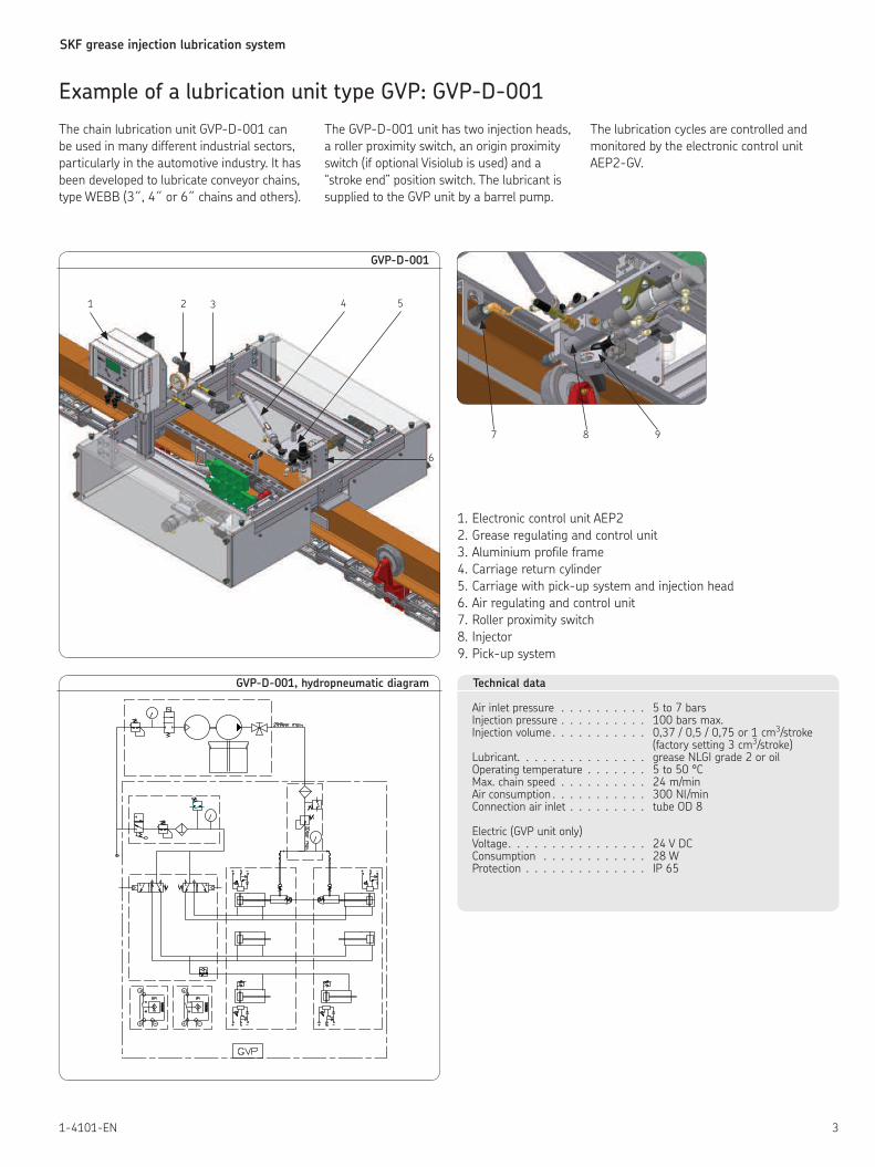
Example of a lubrication unit type GVP: GVP-D-001
1 2 3 4 5
7 8 9
1. Electronic control unit AEP2
2. Grease regulating and control unit
3. Aluminium profile frame
4. Carriage return cylinder
5. Carriage with pick-up system and injection head
6. Air regulating and control unit
7. Roller proximity switch
8. Injector
9. Pick-up system
The chain lubrication unit GVP-D-001 can
be used in many different industrial sectors,
particularly in the automotive industry. It has
been developed to lubricate conveyor chains, type WEBB (3˝, 4˝ or 6˝ chains and others).
Electronic programmable control unit dedicated to the chain lubrication unit type GVP
The AEP2-GV control unit has been especially developed by SKF to
meet the automation requirements of the lubrication process on
industrial conveyor installations. The AEP2-GV unit can control and
monitor a GVP lubrication unit, whatever its configuration.
The main function of the AEP2-GV control unit is to trigger a lubrica-
tion cycle after a pause time has elapsed. This time has been set
previously by the user. The AEP2-GV control unit can manage up to
4 different lubrication cycles. The user can independently set several
main parameters for each cycle in regards to his needs.
• Number of pins: The user enters the exact pin number of the chain.
Then the user can better manage the lubrication process and
exactly identify every pin.
• Lubrication: The user chooses the lubrication frequency, which is
calculated according to the pin number. It is possible either to lubri-
cate all pins during a single chain lap or one pin every “x” number
of pins. Thanks to this parameter, it is easier to adjust the lubrica-
tion process to the chain speed.
• Cycle type: It can be a continuous or a cyclic lubrication process. For
a cyclic lubrication, the pause period can be time-dependent (from
1 hour to 30 days) or load-dependent (up to 1 000 chain laps).
• Injection time: It indicates the time the injection head is in contact
with the pin.
The control unit AEP2-GV is user-friendly due to its LCD display and
six keys. Messages appear on the display in the form
of short texts (several languages available) or graphic symbols.
Technical data
There are three different models of AEP2-GV. The designations, 428, 429 and 924, indicate the operating voltage range (voltage code).
Rated input voltage Unversion +428 . . . . . . . . . . . . . . 100/120 V AC version +429 . . . . . . . . . . . . . . 200/240 V AC version +924 . . . . . . . . . . . . . . 20 ... 24 V DC Input voltage rangeversions +428/+429 . . . . . . . . . . 0,85 Un to 1,1 Un (58 ... 132 V /170 ... 264 V) version + 924 . . . . . . . . . . . . . . 0,85 Un to 1,1 Un (17 ... 26,4 V) Rated frequencyversions +428/+429 . . . . . . . . . . 50/60 Hz Frequency rangeversions +428/+429 . . . . . . . . . . 49 ... 61 Hzversion + 924 . . . . . . . . . . . . . DC Disengaging valueversions +428/+429/+924 . . . . . . . max. 10% of UnReclosing timeversions +428/+429/+924 . . . . . . . 1 s Residual ripple of input voltageversions +428/+429 . . . . . . . . . . not relevantversion + 924 . . . . . . . . . . . . . DC: max. 5%Max. fusingversion + 924 . . . . . . . . . . . . . 4 AMax. switching currentversions +428/+429 . . . . . . . . . . 2 A ACversion + 924 . . . . . . . . . . . . . 0,5 A DC or 2 AMax. relay switching currentversions +428/+429 . . . . . . . . . . 250 V ACversion + 924 . . . . . . . . . . . . . 250 V AC / 24 V DC
(versions +428, +429 and +924)
Rated voltage of inputs . . . . . . . . . 24 V DC Input impedance– digital . . . . . . . . . . . . . . . . 1,8 KΩ ±10%– analog . . . . . . . . . . . . . . . . 15 Ω ±1%Input level, low (digital) . . . . . . . . . 0 V ... 4 VInput level, high (digital) . . . . . . . . 13 V ... 24 VOutput voltage for inputs and external consumers . . . . . . . . 24 V DC +10% / –15%Rated output current (sortie “+’’) . . . . 1A max. included for external consumers . . . . 500 mAPulse inputmax. input frequency . . . . . . . . . . 30 HzPulse duty factor . . . . . . . . . . . . 1:1Protection . . . . . . . . . . . . . . . IP 65Rated isolation voltage . . . . . . . . . 250 V ACService temperature . . . . . . . . . . 0 to 60 °CStorage temperature . . . . . . . . . . –25 to +70 °CSupply voltage / Relay contacts . . . . . 1 780 VSupply voltage / Electronics . . . . . . 2 830 VRelay contacts / Electronics . . . . . . . 2 830 VEMC, noise emission . . . . . . . . . . EN 500081-1
Control unit AEP2-GV
1. Location of the internal wiring
2. RS 232 connector (PC)
3. Additional individual outputs
4. Inputs
5. LCD display
6. Control panel
7. Additional individual inputs
8. Power supply
9. Outputs
2
4
5
6
7
8
9
3
1
SKF grease injection lubrication system
71-4101-EN
Preventive maintenance
– Follow-up control of the conveyor chain state evolution
Active maintenance
– On-site chain state analysis without production stop
The Visiolub software has been especially designed to meet operating
quality requirements of lubrication systems. Combined with the GVP
lubrication system, the Visiolub software controls and monitors in real
time the state of the chain and prevents any production stops due to
chain malfunctions (defective rollers or pins). Thanks to this prevention
tool, the chain’s life is significantly increased.
Visiolub is also very helpful for maintenance department. Information
gathered by Visiolub is key to approving a new lubricant. The program
also makes it easier to determine the correct amount of lubricant
required for optimal lubrication.
Visiolub
Productive maintenance software for chain lubrication systems
Fig. 3
Fig. 1
Fig. 2
Operating principle
Visiolub is directly connected to the lubrication system control unit
AEP2-GV via a computer. Thanks to a pressure sensor mounted on the
injection head, the pressure of each lubricant injection is measured.
The user sets the different parameters corresponding to the lubrica-
tion cycle of the chains – theoretical value, minimal and maximal
values (fig.1). For each chain pin, the user gets a succession of curves
(fig. 2) representing the different grease injections made into this
pin during a lubrication cycle. The analysis of these curves helps the
user to identify possible malfunctions during operation. At the end of
the analysis, a report is generated which informs the user about the
number of defective pins and where they are located (fig 3).
On one hand, Visiolub will help the user confirm the correct operation
of the greasing system. On the other hand, the user will also be able
to identify defective links in the chain and then engage in preventive
maintenance to prevent a chain break.
This brochure was presented by:
Order No.: 1-4101-ENSubject to change without notice! (04/2009)
Important product usage informationAll products from SKF may be used only for their intended purpose as des-cribed in this brochure and in any instructions. If operating instructions are supplied with the products, they must be read and followed.Not all lubricants are suitable for use in centralized lubrication systems. SKF does offer an inspection service to test customer supplied lubricant to determine if it can be used in a centralized system. SKF lubrication systems or their components are not approved for use with gases, liquefied gases, pres-surized gases in solution and fluids with a vapor pressure exceeding normal atmospheric pressure (1013 mbars) by more than 0,5 bar at their maximum permissible temperature.Hazardous materials of any kind, especially the materials classified as hazar-dous by European Community Directive EC 67/548/EEC, Article 2, Par. 2, may only be used to fill SKF centralized lubrication systems and components and delivered and/or distributed with the same after consulting with and receiving written approval from SKF.