User manual Copyright 2016 by SKF Group All rights reserved. SKF Sverige AB Aurorum 30, 977 75 Luleå, Sweden Telephone: +46 (0) 31 337 10 00 SKF Multilog On-Line System IMx-S User Manual Part No. 32087700-EN Revision S – November 2019 WARNING! Read this manual before using the product. Failure to follow the instructions and safety precautions in this manual can result in serious injury, damage to the product, or incorrect readings. Keep this manual in a safe location for future reference.
Transcript
User manual
Copyright 2016 by SKF Group
All rights reserved.
SKF Sverige AB
Aurorum 30, 977 75 Luleå, Sweden
Telephone: +46 (0) 31 337 10 00
SKF Multilog On-Line System IMx-S
User Manual Part No. 32087700-EN Revision S – November 2019
WARNING! Read this manual before using the product. Failure to follow the
instructions and safety precautions in this manual can result in serious injury, damage to
the product, or incorrect readings. Keep this manual in a safe location for future
reference.
SKF Group
® SKF is a registered trademark of the SKF Group.
All other trademarks are the property of their respective owners.
The contents of this publication are the copyright of the publisher and may not be reproduced (even
extracts) unless prior written permission is granted. Every care has been taken to ensure the accuracy of the
information contained in this publication but no liability can be accepted for any loss or damage whether
direct, indirect or consequential arising out of the use of the information contained herein. SKF reserves the
right to alter any part of this publication without prior notice.
Important Messages ............................................... 1-1 System Overview .................................................... 1-2 IMx-S Unit ............................................................... 1-3 System LED Indicators ............................................ 1-4
Environmental ........................................................ 6-1 Power Supply .......................................................... 6-1 Analogue Inputs ...................................................... 6-2 Digital Inputs ........................................................... 6-2 Outputs ................................................................... 6-2
TOC - 2 SKF Multilog On-Line System IMx-S
User Manual – Revision S
Analogue Measurement ........................................ 6-2 Digital Measurement ............................................. 6-3 Signal Processing .................................................... 6-3 Interface ................................................................. 6-4 Data Processing ..................................................... 6-4 Miscellaneous ........................................................ 6-4 Quality Control ....................................................... 6-4
IMx-S Drawings 7
IMx-S 16 Standard Cabinet .................................... 7-1 IMx-S 16 Stainless Steel Cabinet ............................ 7-2 IMx-S 32 Standard & Stainless Steel Cabinet ......... 7-3 Terminal List .......................................................... 7-4
Electrical Waste 8
Limited Warranty A
Index
SKF Multilog On-Line System IMx-S 1 - 1
User Manual – Revision S
1 Introduction
Important Messages
The following messages are important information which require special care in order to
have a safe and reliable IMx-S system.
Important messages, instructions and information in this manual must be
carefully followed. Otherwise, harm might occur to equipment and/or personnel.
In order to install an IMx-S32-UPG-LMU (LMU/CMU upgraded to IMx-S32),
installation must be done according to the "IMx-S32-UPG-LMU Installation manual".
In order to fulfil fire enclosure requirements, ensure the following:
- The cabinet must always be mounted using all four supplied mounting brackets.
- All unused cable ways must be closed with the supplied blind plugs.
- All cable glands and blind plugs must be made of material with fire protection V-1
or better.
Important messages related to mains power (see Mains Power section as well):
- In some countries, the installer must be certified to install equipment such as an
IMx-S.
- Make sure that the power is disconnected before the installation begins.
- Mains cable must be properly fixed with a cable gland to prevent the cord from
strain, twist or movement. See Cable Glands section as well.
- To prevent a hazardous event, mains cable neutral (N) and line (L1) wires must be
secured together with a cable tie (for example, a nylon cable tie CV-100K) close to
the mains power connector.
- The system power supply must be provided with an external all pole power switch
so as to be able to disconnect the IMx-S from mains power. The switch must be
labelled "IMx-S” or si ilar with the On/Off position clearly marked. The switch
must be located close to the IMx-S, within an operator's easy reach.
Introduction
System Overview
1 - 2 SKF Multilog On-Line System IMx-S
User Manual – Revision S
An IMx-S contains circuit boards that are static sensitive. Therefore, use
appropriate precautions to prevent ElectroStatic Discharge (ESD) when handling circuit
boards.
Do NOT change DIP switch settings while the IMx-S unit is powered, as this may
cause damage and void the warranty.
Before powering the IMx-S unit, make sure that DIP switch settings are properly
set to match the recommendations for the connected sensors. Incorrect settings may
cause permanent damage to the IMx-S unit.
All externally provided equipment must be evaluated individually and approved
together with the IMx-S unit regarding EMC and safety requirements (CE and ETL).
Always consult SKF before using the external mains output.
System Overview
The IMx-S is a part of the SKF Multilog On-line System product range and is designed to
be used for a variety of condition monitoring applications. In conjunction with SKF
@ptitude Observer or Analyst software, the IMx-S provides a complete system for early
fault detection and prevention, automatic advice for correcting existing or impending
conditions and advanced condition-based maintenance to improve machine reliability,
availability and performance.
Figure 1 - 1.
System Overview, IMx-S with @ptitude Observer/Analyst.
The picture above illustrates how IMx-S units are linked together in a network that is
connected via a LAN (it may also be a modem or GPRS router) to a SKF @ptitude
Observer Monitor or Analyst IMx Service. The @ptitude Observer Monitor or Analyst
IMx Service in turn can be connected to, for example, a LAN network making it possible
for several @ptitude Observer or Analyst clients to access it.
@ptitude Observer or Analyst clients can also be installed on the same computer as
@ptitude Observer Monitor or Analyst IMx Service login software. Through a general
interface, also known as ODBC (open database connectivity), it is possible to link
Introduction
IMx-S Unit
SKF Multilog On-Line System IMx-S 1 - 3
User Manual – Revision S
@ptitude Observer Monitor or Analyst IMx Service login computer to an existing
database for a control or processing system, if desired. @ptitude Observer Monitor or
Analyst IMx Service, @ptitude Observer or Analyst clients and the database can be
separated from each other as long as they are on the same network where ODBC calls
can travel freely.
It is also possible to connect different types of on-line units in the same network, for
example, IMx-S together with other IMx units and/or MasCon systems.
IMx-S Unit
Figure 1 - 2.
SKF Multilog On-line System IMx-S 16 (left) and IMx-S 32 (right).
IMx-S 16
• Up to 16 analogue channels.
• Up to 8 digital sensors, where 4 of the digital input channels are configurable for all
standard trigger sensors and 4 channels for square pulses with trigger level 12 to
24 V.
• Each IMx-S 16 unit has 8 MB flash memory with the following storage capacity:
– 2 MB for firmware, configuration files, etc.
– 2 MB for trend value buffer.
About 13 000 vibration trend values can be buffered.
Speed and process data use half the space of vibration.
– 4 MB for spectra and time signal buffer.
About 250 spectra using 1 600 lines with phase and time signal can be
buffered.
If more lines are used, the number of spectra is reduced.
Introduction
System LED Indicators
1 - 4 SKF Multilog On-Line System IMx-S
User Manual – Revision S
If less lines are used, the number of spectra is increased.
– When the buffer gets full, the oldest data is thrown away.
IMx-S 32
An IMx-S 32 is essentially composed of two IMx-S 16s.
• Up to 32 analogue channels.
• Up to 16 digital sensors with 8 configurable digital input channels for all standard
trigger sensors and 8 channels for square pulses with trigger level 12 to 24 V.
• IMx-S 32 unit has two CPU cards. Each CPU card separately has 4 MB flash memory
with the same storage capacity of IMx-S 16.
IMx-S features
• Individual conditions for alert and danger may be set for each measurement point.
• Each channel has indicators for alert and danger. Alert and danger levels may be
controlled by machine speed or load. However, it is also possible to manually bypass
the alert and danger functionality.
• The unit's built-in hardware auto-diagnosis system continuously checks all sensors,
cabling and electronics for any faults, signal interruption, short circuits or power
failure.
Initiating an IMx-S
Initiating the IMx-S is straightforward.
• It uses an initiating program @ptitude On-line Device Configurator or Multilog IMx
Configurator tool and a laptop computer using an RS232 serial interface.
• The network configuration parameters, such as IP address, IMx identification
number, etc. are first stored in a separate configuration file, then transferred to the
IMx-S memory. These are retained in the event of power loss, so that the IMx-S can
start automatically when power returns.
System LED Indicators
An IMx-S has two system LEDs on the CPU card.
• Red SYS LED indicates system fault. On means that a system fault has been
detected.
➢ Note that SYS LED is on for a short time when the system is cold
booted or re-started.
• Green PWR LED indicates the status of power. On means that the power is Ok.
SKF Multilog On-Line System IMx-S 2 - 1
User Manual – Revision S
2 Installation
The installation of an IMx-S must be carried out according to the instructions and advice
given in this manual. Any deviation from these directions can be made only after
consulting with the SKF.
Installation errors can lead to a situation where the system does not work as intended
and machinery faults go undetected. In case of questions arising during installation
contact TSG (Technical Support Group) for advice.
➢ Installation errors that require the involvement of SKF personnel
to rectify, may incur additional charges.
Safety Considerations
Observe all site safety requirements including any that may be specific to the machines
or areas where the installation is being carried out. This will likely include, but not be
limited to, PPE (personal protective equipment) and a permit to work.
Important – An IMx-S unit contains circuit boards that are static sensitive.
Therefore, use appropriate precautions to prevent ElectroStatic Discharge (ESD) when
handling circuit boards.
The following are some of the ways to prevent ESD when handling or transferring circuit
boards:
• Use an ESD wrist strap
• Use a grounding mat
• Use correct packaging materials such as anti-static bags
Important - In order to fulfil fire enclosure requirements, the cabinet must always
be mounted using all four supplied mounting brackets.
When mounting the IMx-S unit, make sure that it is firmly attached at a location where it
is not unnecessarily exposed to radiant heat or strong magnetic fields.
The ambient temperature limits for the IMx-S can be found in the Environmental section
of the Technical Data.
Scenario
Before beginning an installation, it is important to assess and evaluate the location
where the system is to be installed and to plan how the installation should look after it
has been completed. For guidance on how and where to attach sensors to machines
Installation
Supply Cable
2 - 2 SKF Multilog On-Line System IMx-S
User Manual – Revision S
ei g o ito ed, efe to the i st u tio a ual: Attaching Sensors for SKF Multilog
On-Line Systems .
Make a detailed layout of the equipment and note distances between components and
the networks to which it should connect. Amongst other things, consider the lengths of
all cables, their routing, where electrical power for the unit can be sourced and any
interfaces to the plant systems. Good and thorough planning is the basis for a successful
installation and system implementation.
Include specifically the IMx-S units, the @ptitude Observer Monitor or Analyst IMx
Service computer, the database server computer and all hubs/routers in the network.
Specify network configuration of each components, such as IP addresses and subnet
masks. SKF application engineers or TSG personnel will need this information in order to
assist.
Note that a CAT5/6 Twisted Pair (TP) Ethernet cable has a maximum working distance of
100 m. If longer cable lengths are needed, fibre optic cables may be used along with
appropriate converters for fibre optic to CAT5/6 (TP) Ethernet and vice versa.
When GPRS is used, the GPRS routers should be reconfigured as a part of the application
to run a lifeline connection with the Observer Monitor or Analyst IMx Service computer.
Important - Failure of this communication path will force the GPRS router to
constantly reboot and can hamper the success of the application. This is especially
important to consider when GPRS forms a part of the customers internal IP network
(VPN). In such a case, SKF must be informed of this before ordering the GPRS, so that
SKF can disable the lifeline functionality of the GPRS router.
Supply Cable
To connect IMx-S to 240 VAC or 120 VAC, the following is recommended:
• FKLK 3 x 1,5 mm2 (16 AWG) or EKLK 3 x 1,5 mm2 (16 AWG) or corresponding, with
minimum voltage requirement 300 V and temperature range of -40 to +70 ºC (-40 to
+158 ºF).
The IMx-S must be connected to protective ground/earth (PE). Refer to Mains Power for
attaching power cable to the mains power/power grid.
Important - The cross-sectional area of the PE wire must be equal or greater than
the cross-sectional area of the power wires. The PE wire should be colour coded
green/yellow. However, in some countries, other cable requirements may apply.
Important - Mains cable must be properly fixed with a cable gland to prevent the
cord from strain, twist or movement. See Cable Glands section as well.
Mains Power
Refer to Power Supply in Technical Data section for power requirements.
Installation
Mains Power
SKF Multilog On-Line System IMx-S 2 - 3
User Manual – Revision S
In order to attach power cable to the mains power grid, follow the directions below.
• First connect the green-yellow wire to the PE (protective earth) terminal.
• Connect the blue wire to the N (neutral) terminal.
• Connect the brown or black wire to the L1 (line) terminal.
Important - Make sure that the power is turned off before working with the
power cable. Touching the leads of a powered cable can cause serious injuries.
Important - In some countries, the installer must be certified to install equipment
such as an IMx-S.
Important - For permanently connected IMx-S an external all pole power switch
must be installed in order to be able to disconnect the IMx-S from the mains power
grid. The switch must be labelled "IMx-S” or si ilar. O /Off positio ust e learly marked. The switch must be located close to the IMx-S, within operator's easy reach.
Important – The fuse holder CANNOT be used as a mains power disconnect
device.
Important - In order to prevent a hazardous event, mains cable neutral (N) and
line (L1) wires must be secured together with a cable tie (for example, a nylon cable tie
CV-100K) close to the mains power connector.
Important - All externally provided equipment must be evaluated individually
and approved together with IMx-S unit regarding EMC and safety requirements (CE
and ETL). Always consult SKF before using the external mains output.
Installation
Sensor Cables
2 - 4 SKF Multilog On-Line System IMx-S
User Manual – Revision S
Figure 2 - 1.
IMx-S Mains Power and Fuse Holder.
As shown in the picture above, the incoming supply live terminal incorporates a fuse
holder that is fitted with a slow blow T2A, 250 V, 5 x 20 mm, fuse.
Sensor Cables
When routing a sensor cable, it is important that the cable is firmly fixed. The cable must
not be allowed to vibrate or oscillate, since this affects the capacitance of the cable, and
thereby the measurement result.
The sensor cable should not be routed or bundled together with supply cables since they
generate strong magnetic fields.
To connect the IMx-S to sensors, the following sensor cable type is recommended:
• Shielded, twisted pair 2 2 0,5 mm2 (FKAR-PG 2 2 0.50, DUE 4002 or
corresponding)
See also Cable Glands section.
Ethernet Cable
For lengths up to 15 metres, it is recommended to use pre-fabricated Ethernet twisted
pair cable FTP type, CAT5/6.
For longer cable lengths, it is recommended to use S-FTP (screened shielded twisted
pair) Ethernet cable CAT5/6.
Installation
Ethernet Connections
SKF Multilog On-Line System IMx-S 2 - 5
User Manual – Revision S
Important - In general, all cables must be routed as far away as possible from
high voltage cabling. If this cannot be done, care should be taken to use high quality
shielded cables, such as S-FTP (screened shielded twisted pair) CAT6 for the network. In
difficult cases, it is the safest to use fibre optic cables.
Ethernet Connections
The IMx-S unit data communications are compliant with the Ethernet standard 10/100
Mbit (half- and full-duplex).
An IMx-S has two, RJ45, Ethernet ports which work like an internal network switch. The
Ethernet TP cable should be connected to one of these ports.
Both Ethernet ports have auto detection of crossover or straight through Ethernet cable
connection. Basically, an IMx-S has a built-in 2-port Ethernet switch. It is possible to
connect several IMx-S units in a daisy chain with up to 8 units in a single cable layout.
There are two LEDs on each RJ45 connector.
• Green LED is the Ethernet link indicator that lights up when the system is correctly
connected to another network device.
• Yellow LED is the Ethernet traffic indicator that flickers whenever there is traffic on
the network.
Cable Glands
If cable shields are to be grounded to the IMx-S unit, then metallic EMC type cable
glands with a 360-degree shield connection are recommended for all cable types except
the mains and communication cable.
• Avoid ground loops via the sensor cables by preferably connecting the shield at, and
only at, the IMx-end.
• Ensure the metal/EMC cable gland has a good 360-degree connection to the IMx-S
enclosure (nut or washer must penetrate any paint or coating on the box).
Important - All unused cable entries must be closed with blind plugs. All cable
glands and blind plugs must be made of material with fire protection V-1 or better. All
cable glands must also meet or exceed IP65 so as to maintain the IP rating of the
enclosure.
SKF Multilog On-Line System IMx-S 3 - 1
User Manual – Revision S
3 Unit Configuration
In general, when referring to DIP switch settings 0 means Off and 1 means On:
Table 3-1: DIP switch setting definition.
DIP Switch Setting Definition
0 OFF
1 ON
Analogue Inputs
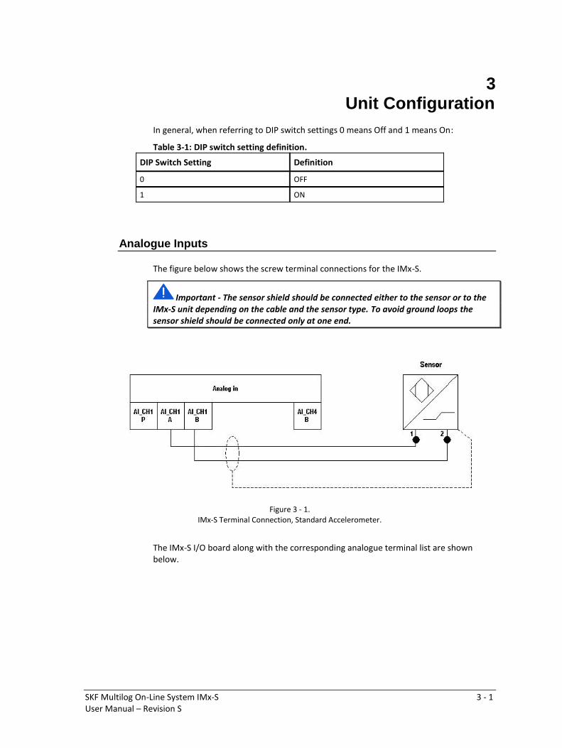
The figure below shows the screw terminal connections for the IMx-S.
Important - The sensor shield should be connected either to the sensor or to the
IMx-S unit depending on the cable and the sensor type. To avoid ground loops the
sensor shield should be connected only at one end.
Figure 3 - 1.
IMx-S Terminal Connection, Standard Accelerometer.
The IMx-S I/O board along with the corresponding analogue terminal list are shown
below.
Unit Configuration
Analogue Inputs
3 - 2 SKF Multilog On-Line System IMx-S
User Manual – Revision S
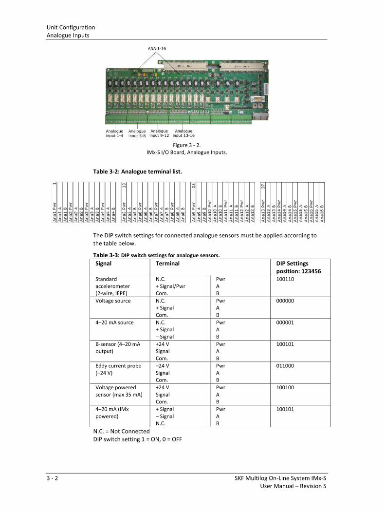
Figure 3 - 2.
IMx-S I/O Board, Analogue Inputs.
Table 3-2: Analogue terminal list.
The DIP switch settings for connected analogue sensors must be applied according to
the table below.
Table 3-3: DIP switch settings for analogue sensors.
Signal Terminal DIP Settings
position: 123456
Standard
accelerometer
(2-wire, IEPE)
N.C.
+ Signal/Pwr
Com.
Pwr
A
B
100110
Voltage source N.C.
+ Signal
Com.
Pwr
A
B
000000
4–20 mA source N.C.
+ Signal
– Signal
Pwr
A
B
000001
B-sensor (4–20 mA
output)
+24 V
Signal
Com.
Pwr
A
B
100101
Eddy current probe
(–24 V)
–24 V
Signal
Com.
Pwr
A
B
011000
Voltage powered
sensor (max 35 mA)
+24 V
Signal
Com.
Pwr
A
B
100100
4–20 mA (IMx
powered)
+ Signal
– Signal
N.C.
Pwr
A
B
100101
N.C. = Not Connected
DIP switch setting 1 = ON, 0 = OFF
Unit Configuration
Digital Inputs
SKF Multilog On-Line System IMx-S 3 - 3
User Manual – Revision S
At maximum ambient temperature, the total sensor power from all inputs must not
exceed:
IMx-S 16 10 W
IMx-S 32 10 W (at 60 ˚C [140 °F] only IEPE sensors are recommended)
At lower temperatures more total sensor power is allowed; please contact TSG or an SKF
application engineer.
Important - Do NOT change DIP switch settings while the IMx-S unit is powered,
as this may cause damage and void warranty.
Important - Before powering the IMx-S unit, make sure that DIP switch settings
are properly set to match the recommendations for the connected sensors. Incorrect
settings may cause permanent damage to the IMx-S unit.
Digital Inputs
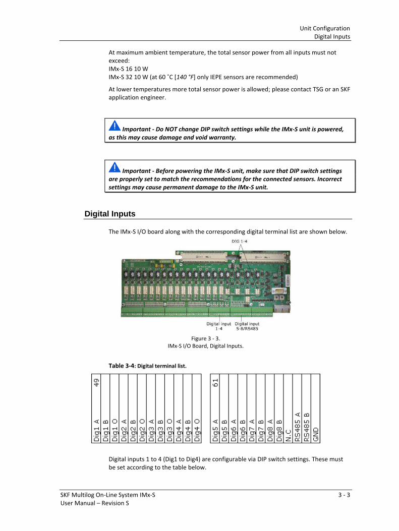
The IMx-S I/O board along with the corresponding digital terminal list are shown below.
Figure 3 - 3.
IMx-S I/O Board, Digital Inputs.
Table 3-4: Digital terminal list.
Digital inputs 1 to 4 (Dig1 to Dig4) are configurable via DIP switch settings. These must
be set according to the table below.
Unit Configuration
Digital Inputs
3 - 4 SKF Multilog On-Line System IMx-S
User Manual – Revision S
Table 3-5: DIP switch setting for digital sensors.
Signal Terminal DIP Settings
position: 1234
(with I/O-board
version less
than v1.24)
DIP Settings
position: 1234
(with I/O board
v1.24 or greater,
with a hole in front
panel for DIP21)
Tacho 2-wire
(24 V internally powered,
max 30 mA)
+
–
N.C.
A
B
O
1010 1011
Tacho 3-wire NPN
(24 V internally powered,
max 30 mA)
Brown (+24 V)
Black (Signal)
Blue (0 V)
A
B
0
0100 0101
Tacho 3-wire PNP
(24 V internally powered,
max 30 mA)
Brown (+24 V)
Black (Signal)
Blue (0 V)
A
B
0
1010 1011
Pulse 12–24 V
(external power)
+
–
N.C.
A
B
O
0100 0101
Pulse TTL
(external power)
N.C.
+
–
A
B
0
1010 1010
N.C. = Not Connected
DIP switch setting 1 = ON, 0 = OFF
DIP position 4 has no effect on the older I/O board (less than V1.24).
Digital inputs 5 to 8 (Dig5 to Dig8) are non-configurable and sensor power is from
external source.
They are only used for externally powered signals with signal level of 12 to 24 V, square
wave signal.
Table 3-6: Digital inputs 5 to 8 terminal list.
Signal Terminal
Pulse 12–24 V
(external power)
+
–
A
B
Unit Configuration
RS485 Communication
SKF Multilog On-Line System IMx-S 3 - 5
User Manual – Revision S
RS485 Communication
Twisted pair shielded cable shall be used.
Important - Connect the shield only at one end to avoid ground loops.
The cable connection should be according to the following:
Table 3-7: Cable connection.
IMx-S RS485 Equipment
RS485 A Out A
RS485 B Out B
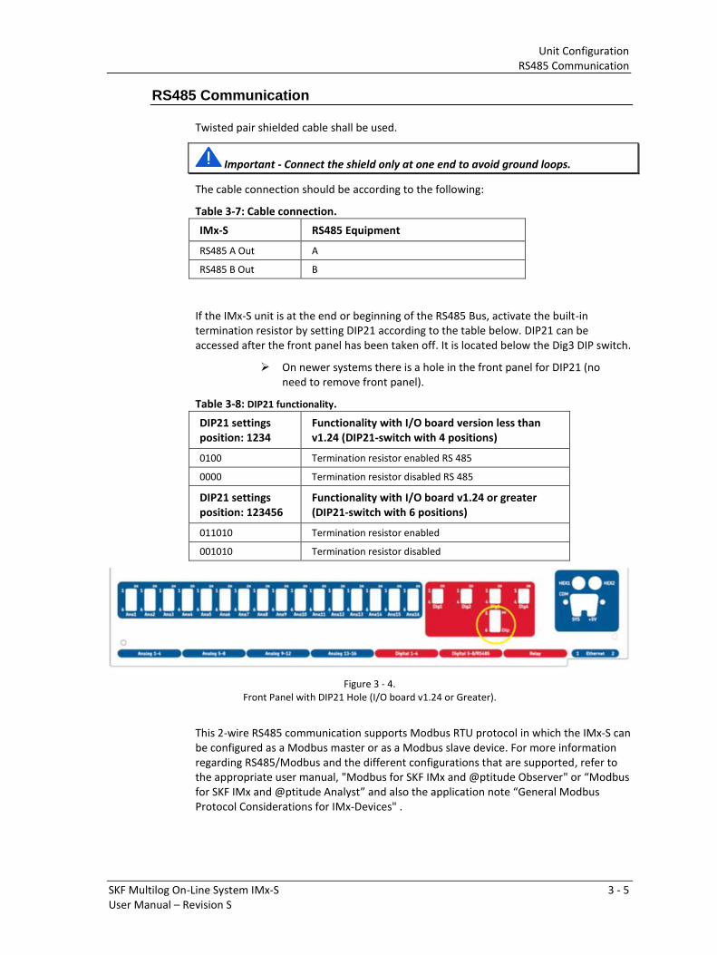
If the IMx-S unit is at the end or beginning of the RS485 Bus, activate the built-in
termination resistor by setting DIP21 according to the table below. DIP21 can be
accessed after the front panel has been taken off. It is located below the Dig3 DIP switch.
➢ On newer systems there is a hole in the front panel for DIP21 (no
need to remove front panel).
Table 3-8: DIP21 functionality.
DIP21 settings
position: 1234
Functionality with I/O board version less than
v1.24 (DIP21-switch with 4 positions)
0100 Termination resistor enabled RS 485
0000 Termination resistor disabled RS 485
DIP21 settings
position: 123456
Functionality with I/O board v1.24 or greater
(DIP21-switch with 6 positions)
011010 Termination resistor enabled
001010 Termination resistor disabled
Figure 3 - 4.
Front Panel with DIP21 Hole (I/O board v1.24 or Greater).
This 2-wire RS485 communication supports Modbus RTU protocol in which the IMx-S can
be configured as a Modbus master or as a Modbus slave device. For more information
regarding RS485/Modbus and the different configurations that are supported, refer to
the appropriate user manual, "Modbus for SKF IMx and @ptitude Observer" o Modbus
for SKF IMx and @ptitude Analyst a d also the appli atio ote Ge e al Mod us Protocol Considerations for IMx-Devices" .
Unit Configuration
Relay Driver Outputs
3 - 6 SKF Multilog On-Line System IMx-S
User Manual – Revision S
Relay Driver Outputs
The IMx-S I/O board has a total of five, relay driver outputs, the board along with the
corresponding relay terminal list are shown below.
Figure 3 - 5.
IMx-S I/O Board, Relays.
Table 3-9: Relay output connection list.
Software Controlled Relay Outputs
Each IMx-S 16 has four and IMx-S 32 has eight software controlled relay driver outputs
labelled as Dig1 OUT through Dig4 OUT (see terminal list above). These relay driver
outputs can be connected to relays as shown in the figure below.
Figure 3 - 6.
Relay Driver Output Connections.
Note that terminals Dig +12V always have the voltage +12 V, whereas terminals Dig1
OUT to Dig4 OUT are low side drivers known as open collectors.
Unit Configuration
Dig1 Buffered Output
SKF Multilog On-Line System IMx-S 3 - 7
User Manual – Revision S
Figure 3 - 7.
Relay Open Collector Driver Showing Alarm Inactive.
System Relay Output
The relay driver output labelled SYSTEM OUT can be connected and used as an external
system alarm indicator.
This is a system fault relay drive that is hardware controlled and cannot be configured by
software.
The system relay driver output is always activated whilst the system is Ok, a "Fail-safe"
configuration.
Important - Total coil current for all five connected relays (Dig1 Out to Dig4 Out
and SYSTEM OUT) should not exceed 300 mA.
Dig1 Buffered Output
Each IMx-S 16 has one and the IMx-S 32 has two digital buffered outputs labelled as Dig1
In Buf Output (a buffered copy of the Dig1 input) as shown in Relay terminal list table,
above.
• Dig1 In Buf Output copies and buffers the signal from digital channel 1 labelled as
Dig1.
• This output is a low-side switch to GND. (The output does not provide any signal
power, just short to GND.)
• This output can be directly connected to a two-wire tachometer input in the other
IMx I/O board.
– Connect Dig1 In Buf Output to Tacho 2-wire input A and connect GND to Tacho
2-wire input B.
• Dig1 In Buf Output and GND are located in last two pins in the relay terminal block.
➢ On I/O board v1.24 and greater, those with a hole in front panel
for DIP21, the phase of the buffered output has been inverted.
This inverted buffered out will then have the same phase as the
input signal.
Unit Configuration
Network Configuration
3 - 8 SKF Multilog On-Line System IMx-S
User Manual – Revision S
➢ This method of cascading a digital input across multiple IMx-S is limited
to applications where the signal frequency is no more than 9 kHz. This
may therefore be unsuitable for applications where a high number of
pulses per rev are being used.
Network Configuration
An IMx-S 16 has one identity number that needs to be configured and also it has to be
assigned one IP address. An IMx-S 32 unit is essentially composed of two IMx-S 16 units;
therefore, it has two (2) identity numbers that need to be configured and also it has to
be assigned with two IP addresses.
The identity numbers must be between 1 and 255 and unique to the database to which
the device is connected. Keep in mind that most of the time, all IMx-S units are on the
same network and database, therefore units can NOT have the same IP address or the
same unit ID.
Configuration also requires the network settings (IP address and port number) of the
@ptitude Observer Monitor or Analyst IMx Service to which the IMx will be connected.
Network configuration uses:
• For Observer clients: Online Device Configurator. For detailed information, refer to
the @ptitude Observer On-line Device Configurator User Manual.
• For Analyst clients: Multilog IMx Configurator in Admin Tools under SKF @ptitude
Monitoring Suite.
There are two ways to configure a network and ID configuration:
• by Software: is configured by the software via On-line Device Configurator or
Multilog IMx Configurator.
• by Hardware Switches: by configuring HEX rotary switches manually.
Configuration by Hardware Switches
If the network is being configured manually by hardware, the following points must be
considered:
• The factory default configuration for the TCP/IP address is 10.0.0.1XY.
• The network configuration requires that the first three parts of the IP address are
set at the Create IMx/MasCon16 Config screen of the On-line Device Configurator or
Multilog IMx Configurator.
• The last, fourth, part of the IP address will be set by the HEX rotary switches on the
IMx-S unit.
• For example, 10.0.0.1XY, where XY will be derived from the HEX rotary switches.
• These last two digits will also form the unit ID.
• The HEX rotary switches are located on the front panel, right hand side marked as
HEX1 and HEX2 above the Ethernet connectors.
• The HEX rotary switches have to be set manually with a small screwdriver.
Unit Configuration
Network Configuration
SKF Multilog On-Line System IMx-S 3 - 9
User Manual – Revision S
Table 3-10: TP/IP address/Unit ID when configured by HEX rotary switches.
TCP/IP
address/Unit ID
HEX1 (x10) HEX2 (x1)
Software defined
01
02
99
0
0
0
9
0
1
2
9
Factory default configuration TCP/IP address:
10.0.0.1XY
Configurator (RS232) Interface
The RS232 interface is only used to set the neccessary network configuration
parameters.
The RS232 connector is located on the right-hand side of the IMx-S front panel, labelled
as COM.
Use a suitable USB to RS232 converter or serial null modem cable with a 9-pin, female,
D-SUB connector to connect to the IMx-S.
It is recommended to use a short length cable for the RS232 interface in order to
maintain full communication speed.
Important – the RS232 connector is to be used only whilst the necessary basic
network configuration setup is being done. The cable should not be connected to, or
left connected to, the RS232 connector at any other time.
Table 3-11: RS232 connector pinout.
RS232 Connector Pinout
Pin Description
1 N.C.
2 Rx
3 Tx
4 N.C.
5 GND
6 N.C.
7 N.C.
8 N.C.
9 N.C.
N.C. = Not Connected
Unit Configuration
IMx-S Time
3 - 10 SKF Multilog On-Line System IMx-S
User Manual – Revision S
Figure 3 - 8.
Null Modem Cable Wiring.
IMx-S Time
IMx-S has a backup power capacitor which will keep the time for at least a month if IMx-
S is disconnected from a power inlet.
To correct or set IMx-S time, use one of the following methods.
• Automatic time synchronization
This method is preferable since the IMx-S will continuously synchronize the
time with the computer that has @ptitude Observer Monitor or Analyst IMx
Service running.
The IMx-S uses a built-in function (NTP) in Windows for time synchronization.
In order to activate time synchronization, refer to Time Synchronization chapter
in "@ptitude Observer Installation Manual".
• Manual set time
Use "Set time" function in @ptitude Observer or @ptitude Analyst application.
In @ptitude Observer, the function is found under a tab menu called "On-line",
then "MasCon/IMx units" interface.
In @ptitude Analyst, the function is found at Transfer / Online / Status.
SKF Multilog On-Line System IMx-S 4 - 1
User Manual – Revision S
4 Hardware Maintenance
The IMx-S hardware, i.e. the IMx-S unit is maintenance free. However, customers are
advised to undertake an annual visual inspection of the equipment.
SKF Multilog On-Line System IMx-S 5 - 1
User Manual – Revision S
5 Troubleshooting Guide
This section is intended as an aid to fault finding, on an IMx-S system. It is designed for
instrumentation engineers and others with sufficient knowledge of electrical
troubleshooting including safe working procedures, on mains powered electronic
systems. Be aware that invasive troubleshooting may cause changes in alarm or channel
status in the IMx-S and any interconnected systems.
Whilst striving to provide information that is as accurate as possible, SKF cannot be held
responsible for any injury or damage to persons or material that occur in the
interpretation of or due to actions taken, based on information in this document.
➢ Note - The product warranty will be invalidated if the IMx-S is
damaged through an incorrect hardware configuration, or if
incorrect connections have been made that expose any sub-
system or circuit to voltages above their operational rating.
Sensor circuits
Possi le auses fo a o - espo si e se so i lude:
• Cable damage, with an open or short circuit in the sensor cable
• Miswiring
• Incorrect DIP switch configuration
• Incorrect software configuration
• Sensor fault
• Hardware fault in IMx-S
• Tacho o l : “peed sig al too eak /i peda e too high fo IMx-S
In addition to, most of, the above, where the sensor generates a higher than expected or
widely varying signal, consider also the following possible causes:
• Incorrectly mounted or loose sensor
• Excitation of sensor mounted resonance
• Signal disturbance due to external noise (for example RFI)
• Grounding issue
• Eddy current probe only: shaft surface damage, probe circuit common inadvertently
grounded at an uninsulated in-line connector or due to cable damage
Troubleshooting Guide
Sensor circuits
5 - 2 SKF Multilog On-Line System IMx-S
User Manual – Revision S
After a visual inspection, deeper troubleshooting of a sensor circuit requires the use of
suitable test equipment, minimum being a digital multimeter (DMM).
Checking vibration channels
The following flow steps can generally be used to troubleshoot a 2-wire accelerometer
that is non-responsive. It is based on checking for the presence of a Bias Output Voltage
(BOV) in an acceptable or expected range.
1. Identify the input terminals where the channel in question is connected to the IMx-S
and measure the DC voltage between the sensor wires at the terminal block using a
digital voltmeter.
2. Is the measured voltage within the expected normal working range? For a typical
accelerometer this would be 8 to 12 V DC.
NO: Skip to step 3.
YES: The cabling to the sensor is probably OK and the sensor interface to the IMx-S
is normal. If the sensor output signal is still perceived as incorrect, then check the
transducer mounting and try substituting the sensor.
a. Did the fault remain after checking the mounting and changing the sensor?
NO: If substituting the sensor cleared the fault then the sensor was defective
and should be replaced.
YES: The fault may be in the analogue input section of the IMx-S device. Contact
TSG for advice and further information.
3. Is the voltage close to zero (typical < ±0,5 V)?
NO: Skip to step 4.
YES: Now, verify that the voltage rises to normal open circuit voltage (about 24 V
DC) when one of the sensor wires is disconnected from the terminal block of the
IMx-S device.
a. Did the voltage rise to normal open circuit voltage?
NO: The IMx-S is not providing sensor power. Check that the IMx-S is correctly
configured to supply sensor power for this channel. If properly configured,
then the IMx-S may be damaged. Contact TSG.
YES: Continue.
b. The fault is in the sensor or its cable. Go to the sensor and disconnect the cable
at this end. Reconnect the cable on the IMx-S terminal block and again
measure the voltage across the two terminals. Does the short circuit remain
(voltage close to zero)?
Whe usi g test e uip e t to easu e ithi ele t o i o t ol i uits su h as se so i i g, e a a e that e e si ple e uip e t su h as a DMM measuring DCV can in some circumstances significantly alter the circuit behaviour.
Be pa ti ula ly autious of usi g i st u e ts that ha e a lo i peda e measure e t fu tio to si ulta eously test fo oltage o o ti uity a d e su e the DCV measurement is being made in a high impedance mode.
Troubleshooting Guide
Sensor circuits
SKF Multilog On-Line System IMx-S 5 - 3
User Manual – Revision S
NO: The sensor is defective. Replace the sensor.
YES: The sensor cable (or contact/connector) has a short circuit and requires
repair/replacement.
4. Is the voltage close to the open circuit voltage?
YES: There is an open circuit in the cable or the sensor is damaged. Skip to step 5.
NO: If the voltage appears to be neither within the normal working range, close to
zero nor close to the open circuit voltage, then the fault is an unusual one.
First, recheck that the DCV measurement was correctly carried out, then
contact TSG for advice.
Remaining faults can be due to a damaged sensor or a damaged IMx-S input circuit. First,
disconnect one pole of the sensor cable and measure the open circuit voltage to verify
whether the open circuit voltage is normal (about 24 V DC). If it is normal, then the fault
is probably in the sensor, otherwise the fault is likely in the IMx-S.
5. Disconnect the connector from the sensor and short circuit the pins in the sensor
contact, then re-measure the voltage on the IMx-S terminal block. Did the voltage
sink to close to zero (<0,5 V)?
NO: There is an open circuit in the cable. Repair/replace the cabling.
YES: There is an internal open circuit in the sensor or there is a bad/oxidised
contact. First, try cleaning the contact before replacing the sensor connector
and checking again.
Checking eddy current probe inputs
Like troubleshooting a 2-wire accelerometer, the checking of eddy current probe inputs
includes confirming the presence of a return signal DC offset in an acceptable or
expected range. In this case however, the sensors are 3-wire, so have a separate wire for
the power supply, and that signal return DC is related to the gap between the probe and
the target or shaft.
1. Identify the input terminals where the channel in question is connected to the IMx-S
and first measure the sensor power supply voltage between Pwr and B at the
terminal block, using a digital voltmeter.
2. Is the measured voltage as expected? For an eddy current probe system this should
be close to -24 V DC, a significantly lower voltage would indicate a fault.
Yes: Skip to step 3.
No: Now remove the sensor wiring from the Pwr terminal and recheck.
a. Did the fault remain?
NO: The sensor circuit appears to be excessively loading the power supply.
Check the sensor circuit cabling for the presence of a short, a similar
measurement with the sensor wiring disconnected at the driver end can be
used to indicate whether the fault lies with the cabling or the driver. Repair
or replace as required.
YES: Check first the configuration settings for this channel, especially the DIP
switches. If all appears as expected, the fault may be with the IMx-S device,
contact TSG for advice and further information.
Troubleshooting Guide
Sensor circuits
5 - 4 SKF Multilog On-Line System IMx-S
User Manual – Revision S
3. Now check the return signal DC bias, between the A and B terminals. As mentioned
the e pe tatio is that this ill a a o di g the p o e/shaft gap, ut fo a i -
a ge easurement can be generally expected to be between -2 and -18 V DC. Is
the return voltage consistent with the probe gap?
NO: Skip to step 4.
YES: The sensor circuit appears to be responding as expected. The fault may be with
the IMx-S device or the software configuration, contact TSG for advice and further
information. If the appropriate work permit and machine isolations are in place to
allow the probe itself to be checked
4. Now continue the checks at the eddy current probe, driver. Is the power supply
voltage at the driver close to -24 V DC? Note that the value measured at the driver
can be expected to be a little lower in magnitude than that measured at the IMx-S
terminals, due to voltage drop.
YES: Skip to step 5.
NO: A cable fault, likely an open or high resistance connection on the Pwr or
common lines, is indicated as the power supply does not seem to be reaching
the driver as expected. Repair or replace as required.
5. At the eddy current probe driver disconnect the signal wire and check the signal DC
voltage at the driver. Is it consistent with the probe gap?
NO: Skip to step 6.
YES: There is a disparity between the signal seen at the driver and that at the IMx-S
terminals. Check for and repair or replace as necessary, an open circuit or poor
connection in the cable signal core. If no cable fault is found recheck the
return signal at the IMx-S but with the signal wire disconnected from the
terminals. Contact TSG for advice and further information, advising them of
the tests undertaken and the findings so far.
6. The tests carried out so far suggest the eddy current probe system is being powered
correctly but is not generating the expected output. Providing the monitored
machine is isolated and there are permits in place for such work, further possible
checks are as follows:
i. Carefully inspect the probe tip for damage and measure the gap to confirm it is
in range.
ii. Change the probe gap and monitor the driver output to check it changes
appropriately. Alternatively as a quick function check, insert a screw driver
blade or metallic feeler gauge between probe and shaft, in this case the
magnitude of the output DC should reduce, towards its minimum value.
iii. Changeout driver and/or probe and compare test results.
Checking 4-20 mA channels
In case of unexpected measurement values, check the hardware DIP switch settings are
correct and review the channel configuration especially scale, zero level and choice of
engineering units. Ensure the correct signal type has been chosen at the DIP switches
and that the wiring is appropriately applied, noting particularly the difference between
loop and IMx powered, 4-20 mA, circuits.
Troubleshooting Guide
Sensor circuits
SKF Multilog On-Line System IMx-S 5 - 5
User Manual – Revision S
Confirm that the signal applied is a 4-20 mA and not for example 0 to 20 mA. Also, be
aware that some 4-20 mA devices will set their outputs low (typically 2.9 mA) or high
(typically 21 mA) to signal a sensor/circuit failure. In such circumstances the output
current will be different to the source, measurement value.
1. Identify the input terminals where the channel in question is connected to the IMx-S
and disconnect one signal wire from the terminal/connector and recomplete the
circuit using a DMM set in current measurement mode. Is the measured current
within the expected range, 4 to 20 mA DC?
YES: Skip to step 2.
NO: This indicates a fault within the sensor loop, IMx load resistor or loop power
supply. Recheck DIP switch settings and all loop connections. If the loop is IMx
powered, disconnect the wiring to the Pwr terminal and check the voltage
between Pwr and A terminals is around 24 V DC. In case of continued
difficulty, contact TSG for advice and further information, advising them of the
tests undertaken so far and details of the current loop being connected.
2. Does the measured mA current reasonably agree with the expected value from the
sensor or system providing the signal?
YES: Problem appears to be related to the IMx (hardware, installation or
configuration). If on rechecking the aspects advised above, no reason for the
measurement error is found, contact TSG for advice.
NO: Recheck all loop wiring and where possible for test purposes, replace the
sensor or loop source by something that will provide a known, fixed current
output, then retest. In case of continued difficulty, contact TSG for advice and
further information, advising them of the tests undertaken so far and details
of the current loop being connected.
Checking analogue input channels
A alogue i puts efe to othe oltage i puts such as voltage sources or powered
voltage sensors rather than accelerometers, eddy current probes or 4-20 mA signals. In
case of unexpected measurement values, check the channel DIP switch settings and the
configuration especially scale, zero level and choice of engineering units. Ensure that the
cable check function enable/disable setting is appropriate for the signal applied.
1. Identify the input terminals where the channel in question is connected to the IMx-S
and verify that the connections are correct. If all appears OK, measure the DC
voltage across the channel input using a digital voltmeter. Is the voltage as expected
for the connected signal type?
NO: Continue to step 2.
YES: The sensor circuit and cabling appear essentially OK, double check the
channel assignment and its configuration. If the measurement is DC and no
reason for the measurement error is found, contact TSG for advice.
If the measurement is AC, it may be necessary to substitute another sensor or simulate a
signal to effectively test the loop.
2. Disconnect the signal wire from terminal A and recheck the DC voltage between
that and the common terminal, B. Is the voltage now as expected, for the connected
signal, type?
Troubleshooting Guide
Sensor circuits
5 - 6 SKF Multilog On-Line System IMx-S
User Manual – Revision S
NO: Problem appears to be related to the signal loop connected to the IMx input.
Continue with further checks on the source equipment and the integrity of the
interconnecting cables.
YES: Problem appears to be related to the IMx (hardware, installation or
configuration) or to a compatibility issue with the sensor. If on rechecking the
aspects advised above, no reason for the measurement error is found, contact
TSG for advice.
Checking digital channels
Be aware that digital inputs 1 to 4 are configurable for different types of sensors, via DIP
switch settings, whilst digital inputs 5 to 8 have fixed characteristics and provide no
sensor power. Refer to Digital Inputs, for further detail.
Effective troubleshooting for tacho signals will likely require a handheld/portable
oscilloscope or DMM with oscilloscope capabilities, a battery powered unit being
preferred. It will be hindered if the IMx-S cannot be accessed when the speed signal is
active.
1. Where applicable, check the sensor installation, the security of the mounting, the
gap to the target and the differential gap between target and no target, conditions.
Ensure these are acceptable for the sensor being used and that the sensor output
will cross the trigger threshold for the particular IMx-S digital channel being used.
2. Identify the digital input terminals where the channel in question is connected to
the IMx-S. Confirm that the wiring is correct for the sensor type in use and where
applicable, the DIP switch settings are correct.
3. Is sensor power, supposed to be, supplied by the IMx-S?
NO: Skip to step 4, dynamic, oscilloscope checks
YES: The sensor must use a digital channel in the range 1 to 4. Measure the DC
voltage between the A (power) and 0 (common) terminals using a digital
voltmeter.
a. Is the measured voltage approximately 24 V DC, as expected?
YES: Skip to step 4, dynamic, oscilloscope checks
NO: Disconnect the sensor cable from the A (power) terminal and recheck the
voltage across the A and 0 terminals.
b. Is the measured voltage now around 24 V DC as expected?
YES: Double check that the sensor is compatible, especially that the sensor current
requirement is within the capability of the IMx-S.
To confirm a sensor/cable fault: if available try substituting an alternative sensor or
confirm that in a known working installation the same type of sensor does not
load the IM se so po e i this a .
NO: The test suggests a fault in the IMx-S, contact TSG for further advice.
4. When a speed signal is expected to be present, observe the signal at the B (signal)
and 0 (common) terminals on an oscilloscope. Is the expected pulsed waveform
present?
NO: Cable, sensor or installation issue. If practicable replace the sensor by a signal
source to test the measurement chain, excluding sensor/target, and to verify
Troubleshooting Guide
Relay driver outputs
SKF Multilog On-Line System IMx-S 5 - 7
User Manual – Revision S
the cable integrity. If the sensor being simulated is an IMx powered 2-wire
device, consider whether the signal generator can dissipate the worst-case
power without damage, and if necessary or in doubt, decouple it from the
IMx-S by a series capacitor.
YES: Verify that the signal has an appropriate voltage range and pulse height to
allow the IMx-S to trigger. Check the software is correctly configured for this
digital input. If no root cause is identified, contact TSG for further advice.
If a speed ha el o ks ut gi es a i o e t speed, he k that the o e t number of
pulses per rev, have been configured in the software.
Relay driver outputs
1. Identify which relay driver output of the IMx-S, is being used for the alarm under
investigation, the expected alarm state and consequently whether it is expected
that the relay coil is currently being energised or not.
2. Is it expected that the coil should be energised?
NO: Skip to step 4.
YES: Measure the DC voltage at the relay coil terminals, using a digital voltmeter.
a. Is the measured voltage 12 V DC, as expected?
YES: Skip to step 3.
NO: Disconnect the relay wiring at the IMx-S and recheck the voltage, across those
terminals.
b. Is the measured voltage now 12 V DC, as expected?
YES: Double check that the relay is compatible with the IMx-S, especially that the
relay current requirement is within its capability, considering also the total of
all relays being used.
Otherwise, a relay or cable fault is indicated.
NO: Check again that the correct relay output is being tested and that the
configuration is correct. If so, the test suggests a fault in the IMx device,
contact TSG for further advice.
3. Disconnect the relay output wiring and using a DMM, measure resistance across the
relay output terminals. Observe the reading and disconnect either of the
connections to the relay coil. Has the reading changed (from an open to a low
resistance or vice versa)?
NO: A relay fault is indicated.
YES: The IMx-S and relay sub-system seems as expected. Check the downstream
system components: that the correct relay output contacts are being used, the
power supply on the relay contact side, the dete ti g de i e, etc.
4. Measure the DC voltage at the relay coil terminals, using a digital voltmeter. Is it
approximately 12 V DC?
YES: Check again that the correct relay output is being tested and that the
configuration is correct. Check also that this relay is wired to the correct IMx-S,
relay driver output.
Troubleshooting Guide
Connections to Monitor
5 - 8 SKF Multilog On-Line System IMx-S
User Manual – Revision S
If so, the test suggests a fault in the IMx device, contact TSG for further advice.
NO: The IMx-S relay driver output seems as expected. Check the downstream
system components: that the correct relay output contacts are being used, the
po e suppl o the ela o ta t side, the dete ti g de i e, etc.
Connections to Monitor
In troubleshooting loss of connections to Monitor, in a multi-IMx system the type of
fault can sometimes be inferred from knowing how many and which IMx have problems
connecting. For multiple connection failures, consider first:
• Whether the PC hosting the Monitor service is currently operational.
• It can access and write to the database.
• If the status of the Monitor software is uncertain, try restarting the PC.
• Check for issues on the network infrastructure, from IMx to that PC.
• Any recent IT changes that may have impacted the system such as firewall, security
changes, etc.
Where Monitor ceases to work with a certain IMx-S unit, consider also:
• Loss of power supply to the IMx-S unit.
• Hardware fault in the IMx-S unit, such as power supply or processor module.
• Break in or failure of the Ethernet network local to that IMx.
At the IMx-S level, check:
• System LEDs on the IMx-S unit. If the system LEDs are OK , check also the Ethernet
LEDs on the RJ45 connectors being used.
• If the problem continues, contact TSG for advice and further guidance.
Checking Modbus RTU, RS485 communication
Communications can be affected by physical, typically wiring, issues for the RS485 bus,
configuration issues related to the Modbus RTU protocol or in some cases third-party
product not adhering to the Modbus RTU specification.
Physically these are, differential, 2-wire interfaces with the two wires marked as A and B.
Whilst it is o al to o e t A to A a d B to B as indicated in Table 3-7, it is not
u hea d of, to ha e i o siste t a ki g o diffe e t a ufa tu e s e uipment. So,
he i te fa i g to e e uip e t a d e pe ie i g p o le s it is o th hile to test with the connections swapped, as no damage will be done by operating with swapped
RS485 connections. Bear in mind if there are multiple issues, say a configuration
problem and an incorrect connection, all issues will have to be solved before a
communications test will be successful. Pay attention also to bus termination and
grounding, as described in Table 3-8.
When using the interface, the connection will be between a single master and one or
sometimes more slave devices, where each slave must have a unique address in the
range 1 to 247. The master device initiates all communications the slave device only ever
responds, if asked to send a reply. Incorrect addressing, such as a mismatch between the
address at which the master understands the slave resides and that actual address, will
result in unanswered messages.
Troubleshooting Guide
Checking Modbus RTU, RS485 communication
SKF Multilog On-Line System IMx-S 5 - 9
User Manual – Revision S
The Modbus RTU protocol exchanges binary data across the bus. Detection of message
start and message end rely on certain bit state combinations and inter-message
minimum pauses, with no communications traffic. For each device on the bus to
correctly interpret these from the electrical patterns on the bus requires an equal
understanding of the bit allocations and the bit rate or baud rate, being used. Commonly
an arrangement known as 8-N-1 (eight data bits, no parity bit and one stop bit)
transmitted at 9 600 or 19 200 bits per second are used. If devices are differently set, by
configuration or otherwise, communications will fail.
The Modbus RTU timing requirements also apply to responses sent when a slave device
is answering a master device command: the response must not start until a time
corresponding to 3.5 characters at the configured baud rate, has elapsed since the end
of the command. SKF has identified that some Modbus transducers do not always
adhere to these requirements and consequently a reply sent without observing the
required 3.5 character gap risks not being recognised as a valid message. In this
eventuality the IMx may be unable to successfully communicate with these Modbus
slaves and unread and input ignored error messages, time-out and frame errors will
result.
Note that although the 3.5 character gap is a hard requirement that should be observed
by all Modbus RTU equipment, it is not an absolute cut-off because the e is a illegal timing area between 1.5 and 3.5 characters to allow inter character and inter message
(frame) gaps to be reliably distinguished. Be aware that as a consequence non-compliant
equipment may work in some test scenarios, such as with a PC master device, but not in
others such as with an IMx master device.
If difficulty is experienced with a particular type of slave and this issue is suspected,
where possible, it may be advantageous to increase the baud to 19 200 as at this higher
rate any fixed response time will correspond to twice the character gap compared to
9 600 baud.
For further information on RS485 and Modbus RTU, refer to the documents listed in the
RS485 Communication section.
When there is access to the IMx-S RS232 service interface, some further diagnostic
checks are possible:
1. Start the @ptitude Observer, On-line Device Configurator.
2. Click Start serial interface.
3. On the Serial interface dialog, select the COM port number and type in the
word "modbus" in the command box.
4. Statistics on communication errors and then summaries for each Modbus
connection will appear on the screen.
The statistics include:
- Frame errors, short and long, and checksum errors
Then for each connection the:
- Number of messages sent (tx) and received (rx)
- Number of request timeouts (to) and exceptions
Each connection has an identifier, example RM1, that uses the following key:
- T/R: TCP or RTU
Troubleshooting Guide
Checking Modbus RTU, RS485 communication
5 - 10 SKF Multilog On-Line System IMx-S
User Manual – Revision S
- M/S: Master or slave
- Number: slave ID
5. A properly working Modbus communication link should exhibit increasing
numbers of messages sent and received, without a significant increase in errors
or timeouts.
6. In case of significant errors or timeouts, check the following aspects:
- That the RS485 cable is correctly, physical connected
- Transmission characteristics are configured correctly
- The Modbus Master-Slave pair address is entered correctly
- RS485 termination is done correctly
7. This process of checking Modbus communication can be repeated, as required
during the installation/test to confirm communications activity or the lack of it.
SKF Multilog On-Line System IMx-S 6 - 1
User Manual – Revision S
6 Technical Data
Environmental
• Size (H x W x D):
Standard cabinet:
– IMx-S 16: 500 400 155 mm (19.7 x 15.7 x 6.1 in.)
– IMx-S 32: 500 500 220 mm (19.7 x 19.7 x 8.7 in.)
Stainless steel cabinet:
– IMx-S 16: 500 400 210 mm (19.7 x 15.7 x 8.3 in.)
– IMx-S 32: 500 500 220 mm (19.7 x 19.7 x 8.7 in.)
• Weight:
Standard cabinet:
– IMx-S 16: 15,0 kg (33.1 lb.)
– IMx-S 32: 21,0 kg (46.3 lb.)
Stainless steel cabinet:
– IMx-S 16: 21,5 kg (47.4 lb.)
– IMx-S 32: 23,1 kg (50.9 lb.)
• Stainless steel grade 304L
• IP rating: IP 65
• Temperature range: –20 to +60 °C (–4 to +140 °F)
• Stainless steel cabinet optional
• Measurement category II
• Pollution degree 2
• Maximum altitude: 2 000 m (6 561.7 ft.)
Power Supply
• 100 to 240 VAC, 47 to 63 Hz
• Power consumption:
– IMx-S 16: 30 W
– IMx-S 32: 60 W
Technical Data
Analogue Inputs
6 - 2 SKF Multilog On-Line System IMx-S
User Manual – Revision S
Analogue Inputs
• Analogue differential inputs:
– IMx-S 16: 16
– IMx-S 32: 32
• Individual 24 V power supply, maximum 35 mA per channel
• Selectable standard accelerometer power supply (4 mA constant current)
• Input range: ±25 V
• Impedance: >100 kΩ
Digital Inputs
• Digital opto-isolated inputs:
– IMx-S 16: 8
– IMx-S 32: 16
• Individual 24 V power supply, maximum 30 mA per channel:
– IMx-S 16: 4 channels
– IMx-S 32: 8 channels
• Trigger level: 2,9 V
– For inputs used with a signal level of 12 to 24 V note that the pulse should be
≥ 12 V.
Outputs
• Relay driver outputs:
– IMx-S 16: 4
– IMx-S 32: 8
• System relay outputs:
– IMx-S 16: 1
– IMx-S 32: 2
Analogue Measurement
• 24-bit AD conversion enabling continuous transient capture (no gain or AC/DC
switching necessary)
• True simultaneous sampling, with no multiplexing:
– IMx-S 16: all 16 channels
– IMx-S 32: all 32 channels
Technical Data
Digital Measurement
SKF Multilog On-Line System IMx-S 6 - 3
User Manual – Revision S
• Simultaneous sampling of different channels with different sampling rates
• Frequency range: from DC to 40 kHz
• Dynamic range: 120 dB
• Signal to noise ratio: 90 dB
• Cross-talk rejection: 100 dB
• Accuracy amplitude: ±2% (up to 20 kHz), ±5% (20 to 40 kHz)
• Accuracy phase: ±3° (up to 100 Hz)
Digital Measurement
• Frequency range: 0,1 Hz to 20 kHz (I/O board v1.24 and later, DIP21-switch with 6
positions)
• Frequency range: 0,1 Hz to 12,5 kHz (I/O board older versions, DIP21-switch with 4
positions)
– Required pulse width: > 4 s for electrical positive
> 40 s for electrical negative
• Accuracy frequency: 0,05% of measurement value (typically 0,01% up to 2,5 kHz)
• Pulse counting
Signal Processing
• Time waveform
• Vector analysis with circular alarms
• FFT: 100 to 6 400 lines
• SKF's four enveloping bands
• Integration/Differentiation in frequency domain
• Window function: Hanning
• Customer formulated mathematical equations
• Dynamic alarm levels, active range determined on multiple parameters
• Data storage on time, event or alarm condition
• Data buffering in flash memory when communication link is down
• Detection of sensor and cable fault
• Watchdog and self-testing
Technical Data
Interface
6 - 4 SKF Multilog On-Line System IMx-S
User Manual – Revision S
Interface
• Ethernet:
• 100 Mbit RJ45, TCP/IP
• 2-port Ethernet network switch (possibility for daisy chaining between IMx-S)
• RS232 service interface
Data Processing
• 64 MB RAM for data processing (from serial number 12000)
Miscellaneous
• Calibration, traceable to BIPM
• CE certified according to EN61000-6-3 and EN61000-6-2
• Support IEC 61850
Quality Control
SKF Sverige AB, Luleå is ISO 9001:2015 certified.
SKF Multilog On-Line System IMx-S 7 - 1
User Manual – Revision S
7 IMx-S Drawings
IMx-S 16 Standard Cabinet
Figure 7 - 1.
IMx-S 16 Standard Cabinet.
IMx-S Drawings
IMx-S 16 Stainless Steel Cabinet
7 - 2 SKF Multilog On-Line System IMx-S
User Manual – Revision S
IMx-S 16 Stainless Steel Cabinet
Figure 7 - 2.
IMx-S 16 Stainless Steel Cabinet.
IMx-S Drawings
IMx-S 32 Standard & Stainless Steel Cabinet
SKF Multilog On-Line System IMx-S 7 - 3
User Manual – Revision S
IMx-S 32 Standard & Stainless Steel Cabinet
Figure 7 - 3.
IMx-S 32 Standard & Stainless Steel Cabinet.
IMx-S Drawings
Terminal List
7 - 4 SKF Multilog On-Line System IMx-S
User Manual – Revision S
Terminal List
Table 8-1: Terminal list.
1 to 48 49 to 84
SKF Multilog On-Line System IMx-S 8 - 1
User Manual – Revision S
8 Electrical Waste
Electrical waste and electrical equipment should be recycled according to the WEEE-
directive and not be placed in the general refuse. Product should be sent to an approved
recycling centre for safe recycling, recovery, reuse or sent to SKF Sverige AB for proper
recycling.
SKF Sverige AB
Aurorum 30
97775 Luleå
Sweden
SKF Multilog On-Line System IMx-S A - 1
User Manual – Revision S
Appendix A Limited Warranty SKF – Limited Warranty
WARRANTY
Subject to the terms and conditions contained
herein and provided that there is no applicable
written agreement between the selling entity in
the “KF G oup “KF a d the Bu e spe ifi all covering the sale of the Products (as defined
below) that includes a product warranty, SKF
warrants to the Buyer that for the warranty
period indicated below the products sold by SKF
that are listed elo the P odu ts , he properly installed, maintained and operated, will
be free from defects in material and
workmanship and shall be fit for the ordinary
purposes for which the Products are designed.
BUYE‘ “ LIMITED ‘EMEDIE“
This limited warranty defi es “KF s sole a d e lusi e lia ilit a d Bu e s sole a d e lusi e remedy for any claim arising out of, or related
to, any alleged deficiency in any Product sold by
SKF, even if such claim is based on tort
(including negligence or strict liability), breach of
contract, or any other legal theory. If the
Product does not conform to this limited
a a t , Bu e ust otif “KF o “KF s authorized service representative within thirty
(30) days of discovery of the nonconformity;
provided, however, that SKF shall not be liable
for any claim for which notice is received by SKF
more than thirty (30) days following the
expiration of the applicable warranty period for
the Product. Upon receipt of timely notification
from Buyer, SKF may, at its sole option, modify,
repair, replace the Product, or reimburse Buyer
for any payment made by Buyer to SKF for the
purchase price of the Product, with such
reimbursement being pro-rated over the
warranty period.
WARRANTY PERIOD
Except as expressly provided below, the
warranty period for each Product shall
commence on the date the Product is shipped
by SKF to Buyer.
90-DAY WARRANTY
Products warranted for ninety (90) days by SKF
are as follows: cable assemblies, MARLIN
QuickConnect (MQC), magnetic temperature
probes, and all refurbished equipment.
ONE-YEAR WARRANTY
Products warranted for one (1) year by SKF are
as follows: all Microlog products and
accessories, all Microlog Inspector applications
including hand-held computers, all MARLIN data
managers (MDM), all MARLIN Condition
Detectors (MCD), all Wireless Machine Condition
Detectors (WMCD), all Multilog Condition
Monitoring Units (CMU, TMU), Multilog Local
Monitoring Units (LMU), all Multilog Wireless
Monitoring Units (WMx), Multilog On-line
System Wireless Vibration Transmitter ISA100,
all Wireless Monitoring Systems V/T, all
Vibration PenPlus, all Machine Condition
Advisors (MCA), all Machine Condition Indicators
(MCI), all transmitters, all Monitor Interface
Modules (MIM), all Machine Condition
Transmitters (MCT), all MicroVibes and Custom
Products with the prefix of CMCP (with the
exception of any consumable or expendable
items), Shaft Alignment Systems TKSA 60 and
TKSA 80 including hand-held computer,
measuring units and accessories.
TWO-YEAR WARRANTY
Products warranted for two (2) years by SKF are
as follows: all standard Eddy Probes, Eddy Probe
Drivers, and Eddy Probe Extension Cables, all
Multilog On-line Systems (IMx) and all Wireless
Machine Condition Sensors.
For all On-line Systems (as defined below) that
have satisfied Criteria 1 and 2 below, the
warranty period shall be either thirty (30)
months from the date the On-line System is
shipped by SKF to Buyer, two (2) years from the
date the On-line System is installed and
commissioned by SKF, or two (2) years from
A - 2 SKF Multilog On-Line System IMx-S
User Manual – Revision S
the date on which the installation of the On-line
System has been audited and commissioned by
SKF or its authorized service representative,
whichever period ends first.
Criteria 1.
Devices used with a Multilog On-line System
(IMx), Multilog Condition Monitoring Unit
(CMU), Multilog Local Monitoring Unit (LMU),
including, but not limited to, the sensing device,
the interconnect cabling, junction boxes, if any,
and the communications interface, must consist
only of SKF-supplied or SKF-approved devices
and/or components. The computer provided by
Buyer must meet the requirements stipulated by
SKF.
Criteria 2.
SKF or its authorized service representative has
installed the On-line System or has audited the
installation and commissioned the On-line
System.
O -li e “ ste s a e defi ed as s ste s consisting of Multilog On-line System (IMx),
Multilog Condition Monitoring Unit(s) (CMU),
Multilog Local Monitoring Unit(s) (LMU), and
any sensing or input devices, the interconnect
cabling between the sensing or input devices
and the Multilog On-line System (IMx), Multilog
Condition Monitoring Unit(s) (CMU), Multilog
Local Monitoring Unit(s) (LMU), and the cabling
between the Multilog On-line System (IMx),
Multilog Condition Monitoring Unit (CMU),
Multilog Local Monitoring Unit (LMU) and the
proprietary SKF communications interface with
the host computer.
FIVE-YEAR WARRANTY
Products warranted for five (5) years by SKF are
as follows: special seismic sensors.
LIMITED LIFETIME WARRANTY
Products covered under this Limited Lifetime
Warranty (as set forth below) are as follows:
standard seismic sensors of the CMSS 2XXX and
CMSS 7XX series (accelerometers and velocity
transducers) as marked and published in the SKF
Vibration Sensor Catalogue.
(A) Subject to the terms herein, SKF will
p o ide a Li ited Lifeti e Wa a t fo the products specified above sold by SKF
after April 15, 2014. Under the Limited
Lifetime Warranty, those products shall,
at the time of shipment, be free from
defects in material and workmanship. If
any of these products fail to meet the
terms of this Limited Lifetime Warranty
during the life of such products, SKF, in its
sole discretion, will repair, replace or
exchange the products for the same
model if the necessary components for
the products are still available to SKF on a
commercially reasonable basis. SKF will
not provide a Limited Lifetime Warranty
on products damaged by accident, abuse,
misuse, neglect, improper installation,
problems with electrical power, natural
disaster, or by any unauthorized
disassembly, repair or modification.
(B) Upon receipt of any product covered by
the Limited Lifetime Warranty, SKF will
pay all shipping charges to send the
repaired, replaced or exchanged product
to the original point of shipment. SKF
reserves the right to decline repair or
replacement if no fault is found in the
product.
(C) For any warranty claim, the original Buyer
must provide SKF with the applicable
model and serial numbers, the date of
purchase, the nature of the problem, and
proof of purchase. SKF, in its sole
discretion, will determine if the Buyer
must return the product covered under
this warranty to SKF.
(D) The express warranty set forth in the
Limited Lifetime Warranty is in lieu of and
excludes any and all other warranties
express or implied,
SKF Multilog On-Line System IMx-S A - 3
User Manual – Revision S
including, but not limited to, the implied
warranties of merchantability and fitness
for a particular purpose.
(E) “KF s sole o ligatio s u de this Li ited Lifetime Warranty are set forth in
pa ag aphs A a d B , a d “KF s lia ility
under this Limited Lifetime Warranty shall
not exceed the purchase price of the
product, plus any shipping and handling
charges that SKF may be obligated to pay
pursuant to paragraph (B).
(F) IN NO EVENT SHALL SKF BE LIABLE OR
OBLIGATED TO THE BUYER OR ANY
OTHER PERSON FOR SPECIAL,
EXEMPLARY, PUNITIVE, INCIDENTAL,
DIRECT, INDIRECT, GENERAL OR
CONSEQUENTIAL DAMAGES (INCLUDING,
BY WAY OF EXAMPLE ONLY, LOST
PROFITS OR SAVINGS, LOSS OF BUSINESS
OR LOSS OF USE) OR ANY OTHER LOSS,
COST OR EXPENSE IN CONNECTION WITH
THE PRODUCTS REGARDLESS OF
WHETHER OR NOT ANY OF THE
FOREGOING WERE FORESEEABLE OR
THAT SKF WAS ADVISED AS TO THE
POSSIBILITY OF SUCH DAMAGES, LOSS,
COST, OR EXPENSE.
(G) The Limited Lifetime Warranty applies
solely to the original Buyer and is non-
transferrable.
OTHER SKF PRODUCTS
Any SKF product supplied hereunder but not
covered by this limited warranty shall be either
covered by the applicable SKF limited warranty
then in place for such product or, if no such
warranty exists, shall be covered by the 90-day
warranty stated above.
THIRD PARTY PRODUCT WARRANTIES
For any third party products sold to Buyer by
SKF, SKF will transfer to Buyer any warranties
made by the applicable third party product
vendor to the extent such warranties are
transferable.
CONDITIONS
As a o ditio to “KF s a a t o ligatio s hereunder and if requested or authorized in
writing by SKF, Buyer shall forward to SKF any
Product claimed by Buyer as being defective.
Buyer shall prepay all transportation charges to
“KF s factory or authorized service center. SKF
will bear the cost of shipping any replacement
P odu ts to Bu e . Bu e ag ees to pa “KF s invoice for the then-current price of any
replacement Product furnished to Buyer by SKF,
if the Product that was replaced is later
determined by SKF to conform to this limited
warranty.
SKF shall not be obligated under this limited
warranty or otherwise for normal wear and tear
or for any Product which, following shipment
and any installation by SKF (if required by the
contra t ith the Bu e , has, i “KF s sole judgment, been subjected to accident, abuse,
misapplication, improper mounting or
remounting, improper lubrication, improper
repair or alteration, or maintenance, neglect,
excessive operating conditions or for defects
caused by or attributable to the Buyer, including
ithout li itatio Bu e s failu e to o pl ith any written instructions provided to Buyer by
SKF.
SKF shall be free to conduct such tests,
investigations and analysis of the Products
returned to SKF, as it deems reasonable and
proper in the exercise of its sole judgment. As a
fu the o ditio to “KF s o ligatio s he eu de , Buyer shall offer its reasonable cooperation to
“KF i the ou se of “KF s e ie of a warranty claim, including, by way of example
o l , Bu e s p o idi g to “KF a a d all information as to service, operating history,
mounting, wiring, or re-lubrication of the
P odu t hi h is the su je t of the Bu e s warranty claim.
EXCEPT WARRANTY OF TITLE AND FOR THE
WARRANTIES EXPRESSLY SET FORTH IN HEREIN,
IT IS UNDERSTOOD AND AGREED THAT:
(A) SKF MAKES NO OTHER WARRANTY,
REPRESENTATION OR
A - 4 SKF Multilog On-Line System IMx-S
User Manual – Revision S
INDEMNIFICATION, EITHER EXPRESS OR
IMPLIED, INCLUDING WITHOUT
LIMITATION ANY IMPLIED WARRANTY
OF MERCHANTABILITY, FITNESS FOR A
PARTICULAR PURPOSE, OR NON-
INFRINGEMENT;
(B) IN NO EVENT SHALL SKF BE LIABLE OR
OBLIGATED FOR SPECIAL, EXEMPLARY,
PUNITIVE, INCIDENTAL, DIRECT,
INDIRECT, GENERAL OR CONSEQUENTIAL
DAMAGES (INCLUDING, BY WAY OF
EXAMPLE ONLY, LOST PROFITS OR
SAVINGS, LOSS OF BUSINESS OR LOSS OF
USE) OR ANY OTHER LOSS, COST OR
EXPENSE IN CONNECTION WITH THE
PRODUCTS AND RELATED SERVICES, IF
ANY, PROVIDED BY SKF, AND THIS
DISCLAIMER SHALL EXTEND AS WELL TO
ANY LIABILITY FOR NONPERFORMANCE
CAUSED BY SKF’S GROSS OR ORDINARY NEGLIGENCE, AND IN ALL CASES