28
SKF Reliability Systems standard product catalogue

SKF Reliability Systems standard product catalogue

SKF Reliability Systems standard product cataloguewww.skf.com/cm2
IntroductionGlobal presence – local solutionsWith over 100 years of experience, SKF stands alone as a total solution provider for maximizing machine and plant productivity. With a reputation for quality, technological innovation and service that spans the globe, SKF brings what no other vendor can to the maintenance arena.
Local SKF sales and service representatives and worldwide distributors provide access to the range of SKF bearings, maintenance products, lubricants and condition monitoring instrumentation and software, independent of your location.
In any kind of rotating machinery, from huge rolling machines to the smallest of motors, the bearing knows if there is a potential problem. As the primary interface between moving parts, the bearing is literally the diagnostic heart of the machine.
Misalignment, unbalance, looseness and friction, are all telegraphed through the bearing. Understanding the information coming from this diagnostic “pulse” and then applying the latest and best technology to the problem is the key to raising machine productivity and lowering operating costs.
This standard product catalogue features a convenient collection of monitoring tools that no industrial manufacturing plant should be without.
Table of contentsSKF Vibration Penplus …………………………………………………………… 3CMVP 40 (in/s) equivalent Peak/CMVP 50 (mm/s) RMS
SKF Inspector 400 Ultrasonic Probe …………………………………… 6CMIN 400-K
SKF Temperature Probe ……………………………………………………… 9CMSS 2000-SL
SKF MicroTemp – Non-contact Thermometer ……………………… 13CMSS 2020
SKF Basic Condition Monitoring Kit ……………………………..……… 15CMPK 200plus/CMPK 210plus
SKF Bearing Analysis Kit ……………………………………………………… 17CMPK 60plus/CMPK 70plus
SKF Machine Condition Detector Pro IS ……………………………… 19CMVL 3600-IS Machine Reliability InspectionSystem – Intrinsically Safety (IS) rated
SKF MicroVibe P ………………………………………………………………… 22CMVL 3850-SL
SKF Loop-powered Vibration Transmitter …………………………… 26CMSS 420VT
Product Support Plans (PSP) ………………………………… Back Cover

SKF Reliability Systems standard product cataloguewww.skf.com/cm
3
SKF Vibration Penplus
CMVP 40, english system (in/s; equivalent Peak)/CMVP 50, metric system (mm/s; RMS)
Overall vibration and enveloped acceleration
OverviewA multi-parameter approach to condition monitoring provides two different methods for monitoring machinery condition. This allows for early detection of specific machinery problems and provides more ways to measure changes in machinery condition.
The SKF Vibration Penplus is a multi-parameter vibration monitoring tool capable of measuring vibration (caused by rotational and structural problems like imbalance, misalignment, looseness, etc.), and capable of measuring vibration in higher frequencies (caused by rolling element bearing or gear mesh problems).
Multi-parameter monitoring is the most thorough and effective method for monitoring bearing and machinery condition. The Vibration Penplus tool’s multi-parameter approach provides accurate and reliable data upon which to base maintenance decisions and promotes early detection, confirmation, and accurate trending of bearing and machinery problems.
Functional descriptionWhen performing measurements, the Vibration Penplus tool’s sensor input signal is processed to produce two different measurements for each machinery POINT, Overall Vibration and enveloped acceleration.
The Vibration Penplus tool’s LCD simultaneously displays both measurement values. Depending on the type and location of the machinery component being measured, either or both readings may be of interest.
Overall vibration(ISO* 10816, Part 1-6) Low frequency vibration (10 Hz to 1 kHz)
Overall velocity vibration occurring in the 10 Hz to 1 kHz frequency band is considered the best operating parameter for judging rotational and structural problems like imbalance, resonance, misalignment, looseness, and stress applied to components.
Many machinery problems may cause excessive overall vibration. Mechanical looseness, imbalance, soft foundation, misalignment, rotor bow, resonance, eccentricity, bad belts, or lost rotor vanes can all be measured with overall ISO* vibration measurements.
Measuring the overall vibration of a machine or component, or the structure of a machine, and comparing the measured value to the machine’s normal value (or to ISO 10816 standards) indicates machinery health and condition changes.
Note: Overall vibration is not an indicator of bearing or gear mesh problems that typically occur in higher frequency ranges.
Enveloped accelerationBearing/gear mesh frequency vibration (10 kHz to 30 kHz)
Enveloped acceleration measurements measure the high frequency repetitive vibration signals typically caused by bearing and gear mesh problems.
Envelope detection is very useful in rolling element bearing and gear mesh analysis where a low amplitude, repetitive vibration signal may be hidden by the machine’s rotational and structural vibration noise.

For example, suppose a rolling element bearing has a defect on its outer raceway. Each rolling element strikes the defect as it passes the defect, causing a small, repetitive vibration signal. This vibration signal is of such low amplitude that, under normal ISO vibration monitoring, it is lost in the machine’s other rotational and structural noise.
Envelope detection filters out low frequency rotational signals, then enhances the high frequency defect signals to focus on repetitive events in the 10 kHz to 30 kHz frequency range, and provides an averaged peak value for early detection of bearing and gear mesh problems.
Note: Enveloped acceleration measurements do not detect rotational or structural vibration caused by imbalance, misalignment, looseness, etc.
Easy operationVibration Penplus readings are easily performed, simply:
Turn the Vibration Penplus on.
Press the Vibration Penplus tool’s sensor tip against your machinery measurement POINT.
Wait for the readings to stabilize, and record the measurement values.
Easy evaluationThe Vibration Penplus tool’s front-panel LCD simultaneously shows overall velocity vibration readings in mm/s RMS (CMVP 50) or in in/s equivalent Peak (CMVP 40), and acceleration enveloping readings in gE (“E” indicating enveloped acceleration).
The SKF Vibration Penplus severity card provides quick reference for ISO Standard 10816 overall velocity vibration comparisons.
•
•
•
The machines are separated into four different groups:
Group 1Large machinery and electrical machines with shaft height greater than 315 mm. These machines are normally equipped with sleeve bearings.
Group 2Medium-size machines and electrical machines with shaft height in between 160 mm and 315 mm.
These machines are normally equipped with rolling element bearings and operating speeds above 600 rpm.
Group 3Pumps with multivane impeller and with separate driver with rated power above 15 kW.
Machines of this group may be equipped with sleeve or rolling element bearings.
Group 4Pumps with multivane impeller and with integrated driver.
Machines of this group mostly have sleeve or rolling element bearings.
SKF Vibration Penplus CMVP 40/CMVP 50
SKF Reliability Systems standard product cataloguewww.skf.com/cm4
General severity level guidelinesWhen considering severity levels, one should always be aware that even standards can only provide general guidelines to determine initial alarm settings. At no time should such guidelines substitute for experience and good judgement. The most reliable method of determining alarm settings is to trend vibration readings over time, establish baseline values and alarm settings above baseline values.
Vibration measured In velocityFor velocity vibration, ISO standards like ISO 10816, First Edition 1995 or VDI 2056 guidelines are generally accepted. ISO 10816 with the title ‘Mechanical vibration – Evaluation of machine vibration by measurements on non-rotating parts’ consists of six parts. Part 1 (10816-1) determines general guidelines and are superseded by the following, more explicit parts of ISO 10816, like part 2 (10816-2) for Land-based steam turbines and generators in excess of 50 MW with normal operating speeds of 1500 r/min, 1800 r/min, 3000 r/min and 3600 r/min.
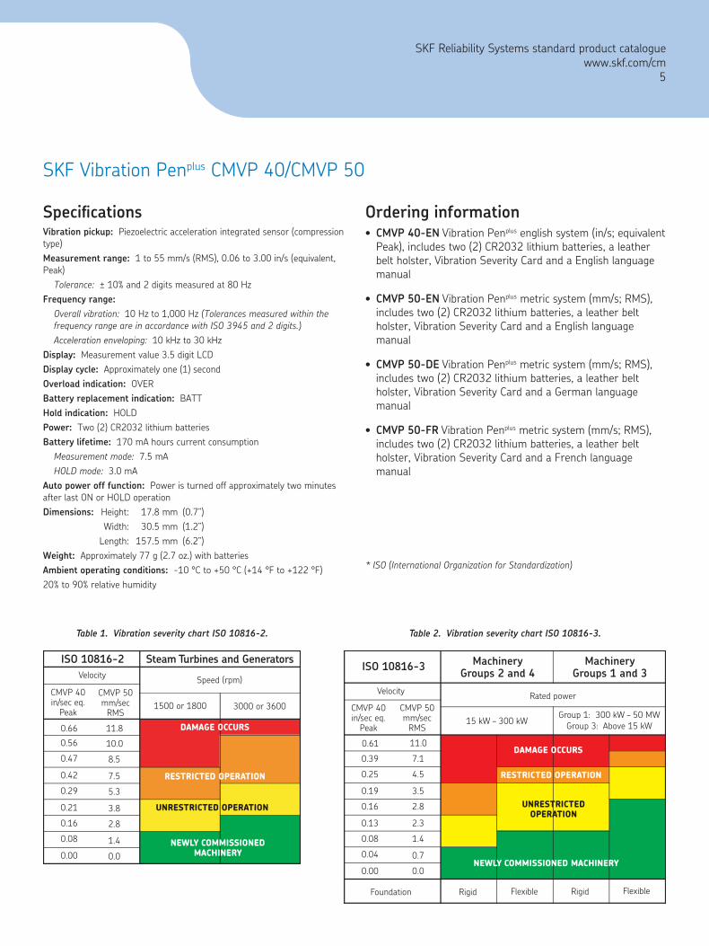
The severity chart shown in Table 1, is in accordance with the ISO 10816-2 guidelines. For exceptions to this guideline and for more details, please refer to the ISO 10816-2 document itself.
Industrial machines with nominal power above 15 kW and nominal speeds between 120 rpm and 15000 rpm when measured in situ are covered by ISO 10816-3.
MachineryGroups 2 and 4ISO 10816-3
CMVP 50mm/sec
RMS15 kW – 300 kW
Group 1: 300 kW – 50 MWGroup 3: Above 15 kW
CMVP 40in/sec eq.
Peak
0.61
0.39
0.25
0.19
0.16
0.13
0.08
0.04
0.00
Velocity Rated power
11.0
7.1
4.5
3.5
2.8
2.3
1.4
0.7
0.0
MachineryGroups 1 and 3
Foundation Rigid Flexible Rigid Flexible
NEWLY COMMISSIONED MACHINERY
UNRESTRICTEDOPERATION
RESTRICTED OPERATION
DAMAGE OCCURS
Table 2. Vibration severity chart ISO 10816-3.
Ordering informationCMVP 40-EN Vibration Penplus english system (in/s; equivalent Peak), includes two (2) CR2032 lithium batteries, a leather belt holster, Vibration Severity Card and a English language manual
CMVP 50-EN Vibration Penplus metric system (mm/s; RMS), includes two (2) CR2032 lithium batteries, a leather belt holster, Vibration Severity Card and a English language manual
CMVP 50-DE Vibration Penplus metric system (mm/s; RMS), includes two (2) CR2032 lithium batteries, a leather belt holster, Vibration Severity Card and a German language manual
CMVP 50-FR Vibration Penplus metric system (mm/s; RMS), includes two (2) CR2032 lithium batteries, a leather belt holster, Vibration Severity Card and a French language manual
* ISO (International Organization for Standardization)
•
•
•
•
SpecificationsVibration pickup: Piezoelectric acceleration integrated sensor (compression type)Measurement range: 1 to 55 mm/s (RMS), 0.06 to 3.00 in/s (equivalent, Peak)
Tolerance: ± 10% and 2 digits measured at 80 HzFrequency range:
Overall vibration: 10 Hz to 1,000 Hz (Tolerances measured within the frequency range are in accordance with ISO 3945 and 2 digits.)Acceleration enveloping: 10 kHz to 30 kHz
Display: Measurement value 3.5 digit LCDDisplay cycle: Approximately one (1) secondOverload indication: OVERBattery replacement indication: BATTHold indication: HOLDPower: Two (2) CR2032 lithium batteriesBattery lifetime: 170 mA hours current consumption
Measurement mode: 7.5 mAHOLD mode: 3.0 mA
Auto power off function: Power is turned off approximately two minutes after last ON or HOLD operationDimensions: Height: 17.8 mm (0.7”) Width: 30.5 mm (1.2”) Length: 157.5 mm (6.2”)Weight: Approximately 77 g (2.7 oz.) with batteriesAmbient operating conditions: -10 °C to +50 °C (+14 °F to +122 °F)20% to 90% relative humidity
Table 1. Vibration severity chart ISO 10816-2.
Steam Turbines and GeneratorsISO 10816-2
CMVP 50mm/sec
RMS1500 or 1800 3000 or 3600
CMVP 40in/sec eq.
Peak
0.66
0.56
0.47
0.42
0.29
0.21
0.16
0.08
0.00
Velocity Speed (rpm)
11.8
10.0
8.5
7.5
5.3
3.8
2.8
1.4
0.0
UNRESTRICTED OPERATION
RESTRICTED OPERATION
DAMAGE OCCURS
NEWLY COMMISSIONEDMACHINERY
SKF Reliability Systems standard product cataloguewww.skf.com/cm
5
SKF Vibration Penplus CMVP 40/CMVP 50
SKF Inspector 400 Ultrasonic ProbeCMIN 400-K
FeaturesDetect pressure and vacuum leaks … including compressed air
Check steam traps and valves quickly and accurately
Detect arcing, tracking and corona in electric apparatus
Test bearings, pumps, motors, compressors, etc.
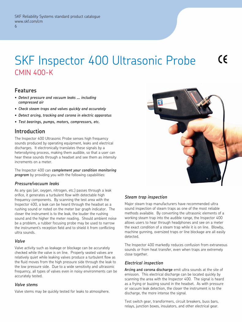
IntroductionThe Inspector 400 Ultrasonic Probe senses high frequency sounds produced by operating equipment, leaks and electrical discharges. It electronically translates these signals by a heterodyning process, making them audible, so that a user can hear these sounds through a headset and see them as intensity increments on a meter.
The Inspector 400 can complement your condition monitoring program by providing you with the following capabilities:
Pressure/vacuum leaksAs any gas (air, oxygen, nitrogen, etc.) passes through a leak orifice, it generates a turbulent flow with detectable high frequency components. By scanning the test area with the Inspector 400, a leak can be heard through the headset as a rushing sound or noted on the meter bar graph indicator. The closer the instrument is to the leak, the louder the rushing sound and the higher the meter reading. Should ambient noise be a problem, a rubber focusing probe may be used to narrow the instrument’s reception field and to shield it from conflicting ultra sounds.
ValveValve activity such as leakage or blockage can be accurately checked while the valve is on line. Properly seated valves are relatively quiet while leaking valves produce a turbulent flow as the fluid moves from the high pressure side through the leak to the low pressure side. Due to a wide sensitivity and ultrasonic frequency, all types of valves even in noisy environments can be accurately tested.
Valve stemsValve stems may be quickly tested for leaks to atmosphere.
•
•
•
•
Steam trap inspectionMajor steam trap manufacturers have recommended ultra sound inspection of steam traps as one of the most reliable methods available. By converting the ultrasonic elements of a working steam trap into the audible range, the Inspector 400 allows users to hear through headphones and see on a meter the exact condition of a steam trap while it is on line. Blowby, machine gunning, oversized traps or line blockage are all easily detected.
The Inspector 400 markedly reduces confusion from extraneous sounds or from heat transfer, even when traps are extremely close together.
Electrical inspectionArcing and corona discharge emit ultra sounds at the site of emission. This electrical discharge can be located quickly by scanning the area with the Inspector 400. The signal is heard as a frying or buzzing sound in the headset. As with pressure or vacuum leak detection, the closer the instrument is to the discharge, the more intense the signal.
Test switch gear, transformers, circuit breakers, buss bars, relays, junction boxes, insulators, and other electrical gear.
SKF Reliability Systems standard product cataloguewww.skf.com/cm6

Left to right: Valve leakage, pressure / vacuum leaks, mechanical inspection and tank leakage.
General mechanical inspectionThe Inspector 400 ultrasonic probe can detect the early stage of a machine’s mechanical malfunction. NASA research has demonstrated that ultrasound monitoring will locate potential bearing deficiencies before they are detected by the traditional heat and vibration methods. With the Inspector 400, users hear the sound quality of a bearing as well as monitor amplitude changes on the meter. This complements other monitoring instruments and adds to the ability to trend, troubleshoot and confirm potential bearing problems.
General mechanical inspection is easy with the Inspector 400 and with very little training, users can learn to test bearings within minutes. Current vibration programs can achieve enhanced diagnostic ability with the Inspector 400.
Prevent over-lubrication with the Inspector 400 by simply lubricating only until the meter reaches a specified level. Over lubrication is one of the more common causes of bearing failure.
General mechanical inspection of pumps, motors, compressors, gears and gear boxes: All types of operating equipment may be inspected with the Inspector 400. Since the Inspector 400 works in a high frequency, short wave environment, problems such as cavitation in pumps, compressor valve leakage or missing gear teeth may be heard and isolated.
Reciprocating compressor valve analysis has also become successful with the Inspector 400 and therefore many engine analyzer companies now offer instruments with an ultrasonic input port.
Heat exchangers, boilers and condensersIn-leakage or pressure leakage can be readily located with the Inspector 400. Fittings, valves, flanges are all easily scanned for leakage. The high frequency, short wave nature of ultrasound allows operators to pinpoint the location of a leak in high noise environments. Condenser tubes and heat exchanger tubes may be tested for leakage through two (2) methods: Vacuum and Pressure.
VacuumThe tube sheet is scanned for the telltale rushing sound produced as the leak draws air into the tube.
PressureAdditional testing may be performed when the system is off-line utilizing air pressure around the tube bundle and scanning for the rushing sound produced from the leaking tube.
SKF Inspector 400 Ultrasonic Probe CMIN 400-K
Application CMIN 400-K
Pressure and vacuum leak detection 3
Valve seat leak detection 3
Exhaust system leaks 3
Heat exchangers, boilers, condensers 3
Steam trap inspection 3
Bearing testing 3
Gear/gear box inspection 3
General mechanical inspection and troubleshooting 3
Tanks, pipes, etc., leak testing 3
Electrical inspection 3
SKF Reliability Systems standard product cataloguewww.skf.com/cm
7

SKF Inspector 400 Ultrasonic Probe CMIN 400-K
Ordering informationCMIN 400-K Inspector 400 Ultrasonic Probe Stethoscope/Scanner Kit
Accessories and replacement partsCMAC 8600-1 Lightweight foam lined headset
CMAC 8600-2 Deluxe noise isolating headphones
CMAC 8600-3 Deluxe noise isolating headphones to be worn with hard hat
CMAC 8600-4 Utility belt with holster
CMAC 8600-5 Patented liquid leak amplifier, case of 12 x 8 oz bottles, (used for extremely low level leaks 1 x 10⁻⁶ mil/sec)
CMAC 8600-6 Stainless steel unisonic scanning module
CMAC 8600-7 Stainless steel stethoscope/contact module
CMAC 8600-8 Stethoscope extension rods
CMAC 8600-9 Rubber focusing probe
Optional kits that includes the CMIN 400-K Inspector 400 Ultrasonic Probe
CMPK 200plus Basic Condition Monitoring Kit
CMPK 210plus Basic Condition Monitoring Kit
•
•
•
•
•
•
•
•
•
•
•
•
Available Inspector 400 Ultrasonic Probe Stethoscope/Scanner kit includes:
Inspector 400 ultrasonic probe pistol housing with LED bar graph meter, 8-position sensitivity selection, low battery indicator
Scanning module
Rubber focusing probe
Stethoscope module
Lightweight foam lined headset
9 volt alkaline battery (replaceable)
Cordura/nylon soft pack carrying case
Comprehensive instruction manual (English language)
SpecificationsConstruction: Hand-held ABS pistol type ultrasonic processor, stainless steel sensor enclosuresCircuitry: SMD/solid state hybrid heterodyne receiverFrequency response: 20–100 kHz (centered at 38–42 kHz)Indicator: 10 segment LED bar graph (red)Sensitivity selection: 8-position precision attenuationPower: 9 volt alkaline batteryLow battery voltage indicator: LEDHeadset: Lightweight foam lined double headset wired monophonic impedance; 16 ohmsProbes: Scanning module stainless steel unisonic (single transducer) piezoelectric crystal type; stethoscope/contact module stainless steel plug-in type with 5.5” stainless steel waveguideRubber focusing probe: Shields stray ultrasonic signals and focuses detected signalsResponse time: 300 millisecAmbient operating temperature range: 0 °C to +50 °C (+32 °F to +120 °F)Relative humidity: 10% to 95% noncondensing at up to +30 °C (+86 °F)Storage temperature: -18 °C to +54 °C (0 °F to +130 °F)Dimensions: Height: 133 mm (5.25”) Width: 50 mm (2.00”) Length: 203 mm (8.00”)Weight: 320 g (11 oz)Carrying case: Cordura/nylon soft pack with die cut foam
•
•
•
•
•
•
•
•
SKF Reliability Systems standard product cataloguewww.skf.com/cm8

SKF Temperature ProbeCMSS 2000-SL
FeaturesSingle point laser sighting
Adjustable emissivity
High and low alarm
MAX, MIN, DIF, AVG temperature displays
Data logging
Trigger lock
Backlit display
Hard case and wrist strap
IntroductionThere are many uses for this hand-held non-contact thermometer. Compact, rugged, and easy to use – just aim, pull the trigger, and read the temperature in less than a second. You can safely measure surface temperatures of hot, hazardous, moving, or hard-to-reach objects without contact.
The non-contact thermometer senses the energy of an object with an infrared detector. When pointed at an object, the infrared detector collects energy producing a signal that the microprocessor translates as a reading on the backlit display. As the trigger is squeezed, the object temperature is continuously measured by the infrared detector. This allows for fast and accurate real-time readings.
Simply point, shoot and read. No contact with hot surfaces or moving parts means safer, faster, and easier temperature measurements.
This instrument features a -32 °C to +600 °C (-25 °F to +1100 °F) temperature range; laser sighting; LCD backlight; MAX, MIN, ∆T, and AVG temperatures; recall last reading,
•
•
•
•
•
•
•
•
Laser Sighted Non-contact Temperature Probe
HI and LOW audible and visual alarms; °C or °F selectable; low battery indicator; recall last reading; and adjustable emissivity for more accurate temperature measurements.
Units are molded from high-strength, solvent-resistant plastic. The optics are recessed for added environmental protection. A cable/strap anchor is provided for the belt clip.
Hard caseA water resistant, dust-proof case which holds the unit (includes belt clip) and measures 245 mm x 169 mm x 52 mm (9.6” x 6.6” x 2.0”) is included.
SKF Reliability Systems standard product cataloguewww.skf.com/cm
9
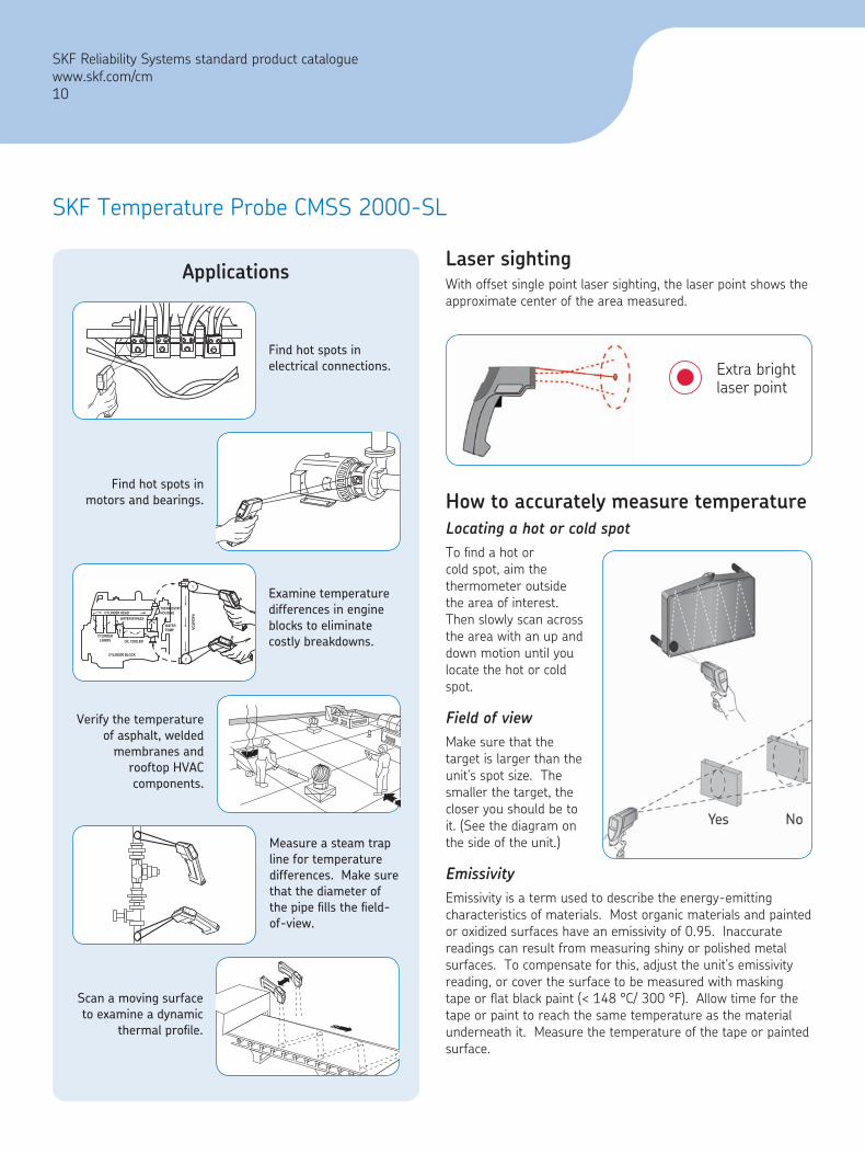
Find hot spots in electrical connections.
Find hot spots in motors and bearings.
Examine temperature differences in engine blocks to eliminate costly breakdowns.
Verify the temperature of asphalt, welded
membranes and rooftop HVAC components.
Measure a steam trap line for temperature differences. Make sure that the diameter of the pipe fills the field-of-view.
Applications
Scan a moving surface to examine a dynamic
thermal profile.
How to accurately measure temperatureLocating a hot or cold spotTo find a hot or cold spot, aim the thermometer outside the area of interest. Then slowly scan across the area with an up and down motion until you locate the hot or cold spot.
Field of viewMake sure that the target is larger than the unit’s spot size. The smaller the target, the closer you should be to it. (See the diagram on the side of the unit.)
EmissivityEmissivity is a term used to describe the energy-emitting characteristics of materials. Most organic materials and painted or oxidized surfaces have an emissivity of 0.95. Inaccurate readings can result from measuring shiny or polished metal surfaces. To compensate for this, adjust the unit’s emissivity reading, or cover the surface to be measured with masking tape or flat black paint (< 148 °C/ 300 °F). Allow time for the tape or paint to reach the same temperature as the material underneath it. Measure the temperature of the tape or painted surface.
Laser sightingWith offset single point laser sighting, the laser point shows the approximate center of the area measured.
Extra brightlaser point
CYLINDERLINERS
CYLINDER HEAD
CYLINDER BLOCK
OIL COOLER
WATER BYPASS
WATERPUMP
THERMOSTAT HOUSING
2
1
RA
DIATO
R
MODE
MODE
MODE
MODE
MODE
MODE
SKF Temperature Probe CMSS 2000-SL
SKF Reliability Systems standard product catalogue www.skf.com/cm10
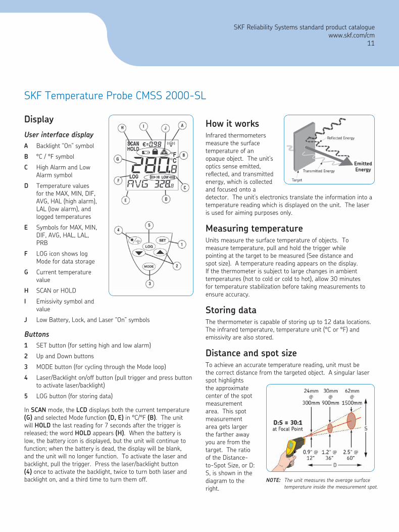
Display
User interface displayA Backlight “On” symbol
B °C / °F symbol
C High Alarm and Low Alarm symbol
D Temperature values for the MAX, MIN, DIF, AVG, HAL (high alarm), LAL (low alarm), and logged temperatures
E Symbols for MAX, MIN, DIF, AVG, HAL, LAL, PRB
F LOG icon shows log Mode for data storage
G Current temperature value
H SCAN or HOLD
I Emissivity symbol and value
J Low Battery, Lock, and Laser “On” symbols
Buttons1 SET button (for setting high and low alarm)
2 Up and Down buttons
3 MODE button (for cycling through the Mode loop)
4 Laser/Backlight on/off button (pull trigger and press button to activate laser/backlight)
5 LOG button (for storing data)
In SCAN mode, the LCD displays both the current temperature (G) and selected Mode function (D, E) in °C/°F (B). The unit will HOLD the last reading for 7 seconds after the trigger is released; the word HOLD appears (H). When the battery is low, the battery icon is displayed, but the unit will continue to function; when the battery is dead, the display will be blank, and the unit will no longer function. To activate the laser and backlight, pull the trigger. Press the laser/backlight button (4) once to activate the backlight, twice to turn both laser and backlight on, and a third time to turn them off.
How it worksInfrared thermometers measure the surface temperature of an opaque object. The unit’s optics sense emitted, reflected, and transmitted energy, which is collected and focused onto a detector. The unit’s electronics translate the information into a temperature reading which is displayed on the unit. The laser is used for aiming purposes only.
Measuring temperatureUnits measure the surface temperature of objects. To measure temperature, pull and hold the trigger while pointing at the target to be measured (See distance and spot size). A temperature reading appears on the display. If the thermometer is subject to large changes in ambient temperatures (hot to cold or cold to hot), allow 30 minutes for temperature stabilization before taking measurements to ensure accuracy.
Storing dataThe thermometer is capable of storing up to 12 data locations. The infrared temperature, temperature unit (°C or °F) and emissivity are also stored.
Distance and spot sizeTo achieve an accurate temperature reading, unit must be the correct distance from the targeted object. A singular laser spot highlights the approximate center of the spot measurement area. This spot measurement area gets larger the farther away you are from the target. The ratio of the Distance-to-Spot Size, or D:S, is shown in the diagram to the right.
NOTE: The unit measures the average surface temperature inside the measurement spot.
SKF Temperature Probe CMSS 2000-SL
SKF Reliability Systems standard product cataloguewww.skf.com/cm
11
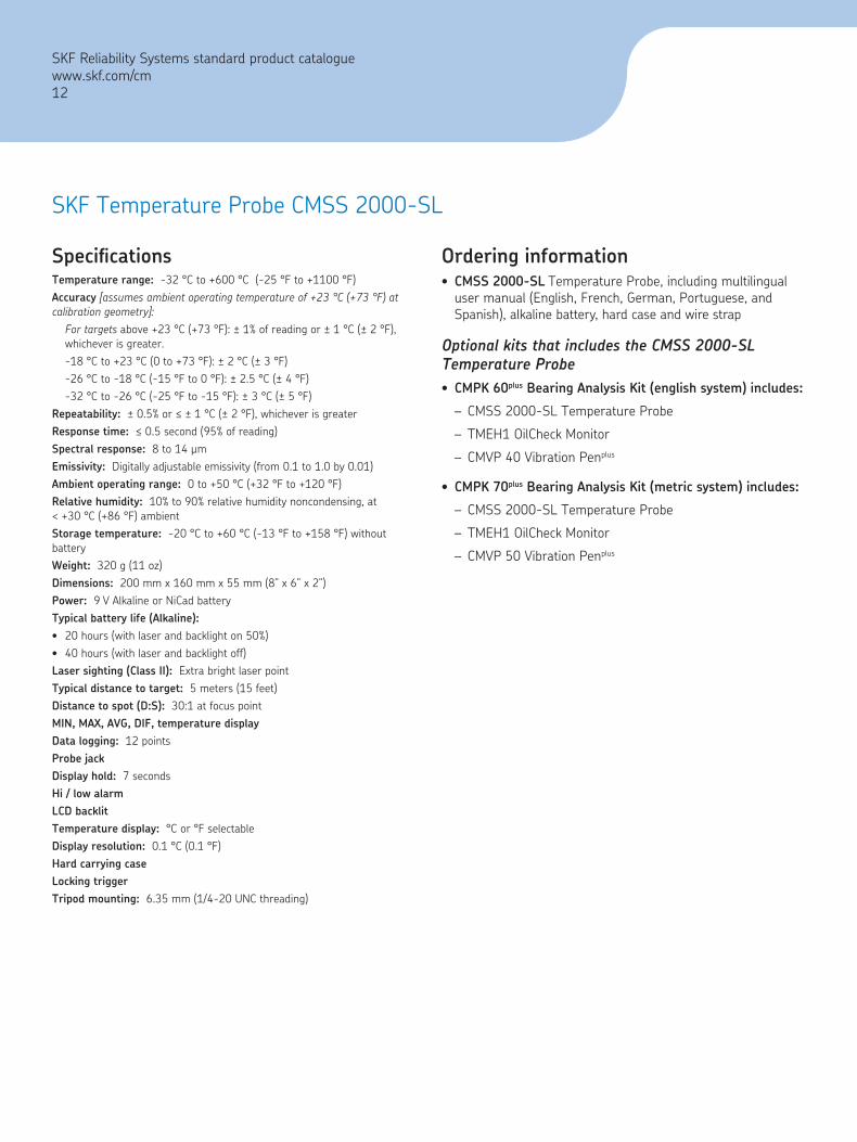
SpecificationsTemperature range: -32 °C to +600 °C (-25 °F to +1100 °F)Accuracy [assumes ambient operating temperature of +23 °C (+73 °F) at calibration geometry]:
For targets above +23 °C (+73 °F): ± 1% of reading or ± 1 °C (± 2 °F), whichever is greater.-18 °C to +23 °C (0 to +73 °F): ± 2 °C (± 3 °F)-26 °C to -18 °C (-15 °F to 0 °F): ± 2.5 °C (± 4 °F)-32 °C to -26 °C (-25 °F to -15 °F): ± 3 °C (± 5 °F)
Repeatability: ± 0.5% or ≤ ± 1 °C (± 2 °F), whichever is greaterResponse time: ≤ 0.5 second (95% of reading)Spectral response: 8 to 14 µmEmissivity: Digitally adjustable emissivity (from 0.1 to 1.0 by 0.01)Ambient operating range: 0 to +50 °C (+32 °F to +120 °F)Relative humidity: 10% to 90% relative humidity noncondensing, at < +30 °C (+86 °F) ambientStorage temperature: -20 °C to +60 °C (-13 °F to +158 °F) without batteryWeight: 320 g (11 oz)Dimensions: 200 mm x 160 mm x 55 mm (8” x 6” x 2”)Power: 9 V Alkaline or NiCad batteryTypical battery life (Alkaline):
20 hours (with laser and backlight on 50%)40 hours (with laser and backlight off)
Laser sighting (Class II): Extra bright laser pointTypical distance to target: 5 meters (15 feet)Distance to spot (D:S): 30:1 at focus pointMIN, MAX, AVG, DIF, temperature displayData logging: 12 pointsProbe jackDisplay hold: 7 secondsHi / low alarmLCD backlitTemperature display: °C or °F selectableDisplay resolution: 0.1 °C (0.1 °F)Hard carrying caseLocking triggerTripod mounting: 6.35 mm (1/4-20 UNC threading)
••
Ordering informationCMSS 2000-SL Temperature Probe, including multilingual user manual (English, French, German, Portuguese, and Spanish), alkaline battery, hard case and wire strap
Optional kits that includes the CMSS 2000-SL Temperature Probe
CMPK 60plus Bearing Analysis Kit (english system) includes:
CMSS 2000-SL Temperature Probe
TMEH1 OilCheck Monitor
CMVP 40 Vibration Penplus
CMPK 70plus Bearing Analysis Kit (metric system) includes:
CMSS 2000-SL Temperature Probe
TMEH1 OilCheck Monitor
CMVP 50 Vibration Penplus
•
•
–
–
–
•
–
–
–
SKF Temperature Probe CMSS 2000-SL
SKF Reliability Systems standard product cataloguewww.skf.com/cm12

SKF MicroTemp –Non-contact ThermometerCMSS 2020-SL
FeaturesLaser sighted
Fast and easy-to-use
Compact, rugged size
IntroductionThe SKF MicroTemp – Non-contact Thermometer CMSS 2020 takes the surface temperature of almost any object quickly and easily. Just aim, pull the trigger, and read the temperature on the display. Surface temperatures of hot, hazardous, or hard-to-reach objects can safely be measured without contact.
Its compact size makes it handy for use in the electrical/industrial, automotive/diesel, food safety and various other industries.
Non-contact thermometer uses
•
•
•
Electrical/industrial
Food safety
Automotive and diesel
SKF Reliability Systems standard product cataloguewww.skf.com/cm
13
SKF MicroTemp – Non-contact Thermometer CMSS 2020-SL
SpecificationsRecommended target ranges: The unit’s distance-to-target spot size ratio is 6:1. For best results, make sure the target is larger than the unit’s spot size.Temperature range: -18 °C to +260 °C (0 to +500 °F)Accuracy: For targets at:
-1 °C to +260 °C (+30 °F to +500 °F) ± 2% of readingor ± 2 °C (± 3.5 °F) whichever is greater;-18 °C to -1 °C (0 to +30 °F) ± 3 °C (± 5 °F)
Weight: 227 g (0.5 lb)Dimensions: 152 mm x 101 mm x 38 mm (6.0” x 4.0” x 1.5”)Ambient operating range: 0 to +50 °C (+32 °F to +120 °F)Relative humidity: 10% to 95% relative humidity noncondensing, at up to +30 °C (+86 °F)Power: 9 V Alkaline or NiCad battery
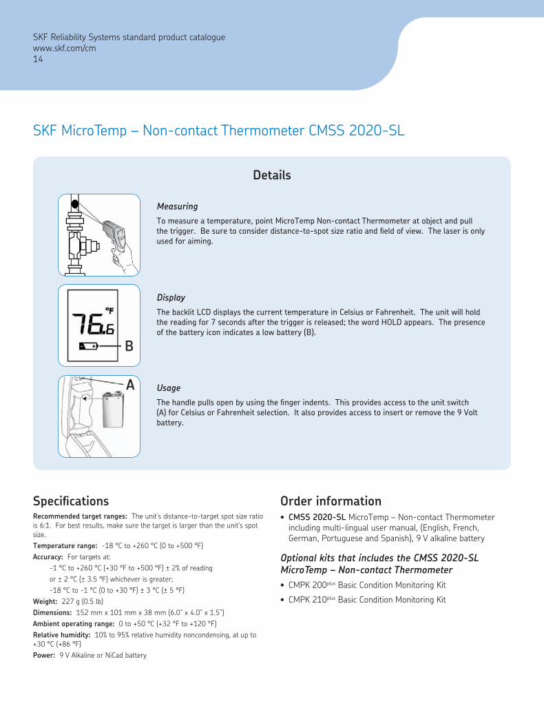
MeasuringTo measure a temperature, point MicroTemp Non-contact Thermometer at object and pull the trigger. Be sure to consider distance-to-spot size ratio and field of view. The laser is only used for aiming.
Details
DisplayThe backlit LCD displays the current temperature in Celsius or Fahrenheit. The unit will hold the reading for 7 seconds after the trigger is released; the word HOLD appears. The presence of the battery icon indicates a low battery (B).
UsageThe handle pulls open by using the finger indents. This provides access to the unit switch (A) for Celsius or Fahrenheit selection. It also provides access to insert or remove the 9 Volt battery.
Order informationCMSS 2020-SL MicroTemp – Non-contact Thermometer including multi-lingual user manual, (English, French, German, Portuguese and Spanish), 9 V alkaline battery
Optional kits that includes the CMSS 2020-SL MicroTemp – Non-contact Thermometer
CMPK 200plus Basic Condition Monitoring Kit
CMPK 210plus Basic Condition Monitoring Kit
•
•
•
SKF Reliability Systems standard product cataloguewww.skf.com/cm14

SKF Basic Condition Monitoring KitCMPK 200plus metric system/CMPK 210plus english system
Check bearing and machine condition quickly and easily.Reduce unexpected downtime.
An essential collection of monitoring tools that no industrial manufacturing plant should be without. Makes condition monitoring a simple task for maintenance, operations, reliability and vibration analysis departments.
A powerful combination for detection of machine and bearing defects
Multi-parameter condition monitoring:
Vibration Penplus CMVP 40/CMVP 50
MicroTemp – Non-contact Thermometer CMSS 2020
Inspector 400 Ultrasonic Probe CMIN 400
CMPK 200plus Kit (metric system) includes:• CMVP 50, metric system (mm/s, RMS) Vibration Penplus with
carrying case
• CMSS 2020 MicroTemp – Non-contact Thermometer
• CMIN 400 Inspector 400 Ultrasonic Probe with headphones
• Batteries included
• Vibration severity card
• Belt holder for the Vibration Penplus
• Comprehensive quick start instruction card
• Rugged carrying case
•
•
•
•
•
CMPK 210plus Kit (english system) includes:CMVP 40, english system (in/s, equivalent peak) Vibration Penplus with carrying case
CMSS 2020 MicroTemp – Non-contact Thermometer
CMIN 400 Inspector 400 Ultrasonic Probe with headphones
Batteries included
Vibration severity card
Belt holder for the Vibration Penplus
Comprehensive quick start instruction card
Rugged carrying case
•
•
•
•
•
•
•
•
SKF Reliability Systems standard product cataloguewww.skf.com/cm
15

SKF Vibration Penplus
CMVP 40 (in/s equivalent Peak) / CMVP 50 (mm/s RMS)
SKF Basic Condition Monitoring Kit CMPK 200plus/CMPK 210plus
The SKF Basic Condition Monitoring Kit consists of:
So light and compact it fits in your shirt pocket
Easy to operate
Measures according to ISO 10816 standards
For additional information, please refer to the previous section containing the Vibration Penplus.
•
•
•
SKF Inspector 400 Ultrasonic ProbeCMIN 400
Detect pressure and vacuum leaks … including compressed air
Check steam traps and valves quickly and accurately
Detect arcing, tracking and corona in electric apparatus
Test bearings, pumps, motors, compressors, etc.
For additional information, please refer to the previous section containing the Inspector 400 Ultrasonic Probe.
•
•
•
•
SKF MicroTemp – Non-contact ThermometerCMSS 2020
Laser sighted
Fast and easy-to-use
Compact, rugged size
For additional information, please refer to the previous section containing the SKF MicroTemp – Non-contact Thermometer.
•
•
•
SKF Reliability Systems standard product catalogue www.skf.com/cm16
Ordering informationCMPK 200 PLUS-EN Basic Condition Monitoring Kit includes:
CMVP 50-EN Vibration Penplus metric system (mm/s; RMS), with English user manualCMSS 2020-SL MicroTemp – Non-contact ThermometerCMIN 400-K Inspector 400 Ultrasonic Probe with headphonesCustom hard-shell carrying caseBatteries included
CMPK 200 PLUS-DE Basic Condition Monitoring Kit includes:
CMVP 50-EN Vibration Penplus metric system (mm/s; RMS), with German user manualCMSS 2020-SL MicroTemp – Non-contact ThermometerCMIN 400-K Inspector 400 Ultrasonic Probe with headphonesCustom hard-shell carrying caseBatteries included
CMPK 200 PLUS-FR Basic Condition Monitoring Kit includes:
CMVP 50-EN Vibration Penplus metric system (mm/s; RMS), with French user manualCMSS 2020-SL MicroTemp – Non-contact ThermometerCMIN 400-K Inspector 400 Ultrasonic Probe with headphonesCustom hard-shell carrying caseBatteries included
CMPK 210 PLUS-EN Basic Condition Monitoring Kit includes:
CMVP 50-EN Vibration Penplus english system (in/s; equivalent Peak), with English user manualCMSS 2020-SL MicroTemp – Non-contact ThermometerCMIN 400-K Inspector 400 Ultrasonic Probe with headphonesCustom hard-shell carrying caseBatteries included
•
–
–
–
––
•
–
–
–
––
•
–
–
–
––
•
–
–
–
––

Check bearing and machine condition quickly and easily.Reduce unexpected downtime.
A convenient collection of monitoring tools that no industrial manufacturing plant should be without. Makes condition monitoring a simple task for maintenance, operations, reliability and vibration analysis departments.
Monitor vibration, temperature and oil condition with:
Vibration Penplus CMVP 40/CMVP 50
Non-contact Temperature Probe CMSS 2000-SL
OilCheck Monitor TMEH1
CMPK 60plus Bearing Analysis Kit (english system) includes:
CMVP 40, english system (in/s, equivalent peak) Vibration Penplus with manual, carrying case, severity card, and battery
CMSS 2000-SL Laser Sighted Non-contact Temperature Probe with manual, hard case, belt clip, and battery
SKF TMEH1 OilCheck with manual, soft carrying case, and battery
Custom hard-shell carrying case
CMPK 70plus Bearing Analysis Kit (metric system) Includes:
CMVP 50, metric system (mm/s, RMS) Vibration Penplus with manual, carrying case, severity card, and battery
CMSS 2000-SL Laser Sighted Non-contact Temperature Probe with manual, hard case, belt clip, and battery
SKF TMEH1 OilCheck with manual, soft carrying case, and battery
Custom hard-shell carrying case
•
•
•
•
•
•
•
•
•
•
•
•
•
SKF Bearing Analysis KitCMPK 60plus english system/CMPK 70plus metric system
SKF Reliability Systems standard product cataloguewww.skf.com/cm
17
Ordering informationCMPK 60 PLUS-EN Bearing Analysis Kit includes:
CMVP 40-EN Vibration Penplus english system (in/s; equivalent Peak), with English user manual CMSS 2000-SL Temperature Probe, including hard case and wrist strap, multilingual user manual (English, French, German, Portuguese and Spanish)TMEH1 OilCheck Monitor, soft carrying case, manual in English languageCustom hard-shell carrying caseBatteries included
CMPK 70 PLUS-EN Bearing Analysis Kit includes:CMVP 50-EN Vibration Penplus metric system (mm/s; RMS), with English user manualCMSS 2000-SL Temperature Probe, including hard case and wrist strap, multilingual user manual (English, French, German, Portuguese and Spanish)TMEH1 OilCheck Monitor, soft carrying case, manual in English languageCustom hard-shell carrying caseBatteries included
•–
–
–
––
•–
–
–
––
SKF Bearing Analysis Kit CMPK 60plus/CMPK 70plus
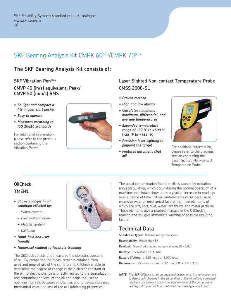
Shows changes in oil condition effected by:
Water content
Fuel contamination
Metallic content
Oxidation
Hand-held and user friendly
Numerical readout to facilitate trending
The OilCheck detects and measures the dielectric constant of oil. By comparing the measurements obtained from used and unused oils of the same brand, OilCheck is able to determine the degree of change in the dielectric constant of the oil. Dielectric change is directly related to the degradation and contamination level of the oil and helps the user to optimize intervals between oil changes and to detect increased mechanical wear and loss of the oils lubricating properties.
•
–
–
–
–
•
•
Proven method
High and low alarms
Calculates minimum, maximum, differential, and average temperatures
Expanded temperature range of -32 °C to +500 °C (-25 °F to +932 °F)
Precision laser sighting to pinpoint the target
Features automatic shut off
•
•
•
•
•
•
The SKF Bearing Analysis Kit consists of:
SKF Vibration Penplus
CMVP 40 (in/s) equivalent, Peak/ CMVP 50 (mm/s) RMS
So light and compact it fits in your shirt pocket
Easy to operate
Measures according to ISO 10816 standards
For additional information, please refer to the previous section containing the Vibration Penplus.
•
•
•
Laser Sighted Non-contact Temperature ProbeCMSS 2000-SL
For additional information, please refer to the previous section containing the Laser Sighted Non-contact Temperature Probe.
OilCheckTMEH1
The usual contamination found in oils is caused by oxidation and acid build up, which occur during the normal operation of a machine and should show up as a gradual increase in readings over a period of time. Other contaminants occur because of excessive wear or mechanical failure, the main elements of which are dirt, soot, fuel, water, antifreeze and metal particles. These elements give a marked increase in the OilCheck’s reading and will give immediate warning of possible resulting failure.
Technical DataSuitable oil types: Mineral and synthetic oils
Repeatability: Better than 5%
Readout: Green/red grading, numerical value (0 – 100)
Battery: 9 V Alkaline IEC 6LR61
Battery lifetime: > 150 hours or 3,000 tests
Dimensions: 250 mm x 95 mm x 32 mm (9.8” x 3.7” x 1.3”)
NOTE: The SKF OilCheck is not an analytical instrument. It is an instrument to detect only changes in the oil condition. The visual and numerical readouts are purely a guide to enable trending of the comparative readings of a good oil to a used oil of the same type and brand.
SKF Reliability Systems standard product cataloguewww.skf.com/cm18

The SKF Machine Condition Detector Pro IS(MCD Pro IS) is certified Intrinsically Safe (IS) for Europe and North America. The ruggedized MCD Pro IS is ideal for use in the hazardous environments typically found in the petrochemical Industrial marketplace.
Go / No Go machine monitoringThe Machine Condition Detector Pro IS is designed to provide a straightforward approach to machinery monitoring. The instrument’s sensor affixes to a machine point via a MARLIN QuickConnect (MQC) Stud or magnetic bases for automatic collection of vibration and temperature data. Green, yellow and red LEDs provide easy-to-interpret indications of machine status, so operations or maintenance personnel can quickly identify the need for more in-depth analysis on a particular machine.
Multi-parameter monitoring capabilitiesThe Machine Condition Detector Pro IS operates as a stand-alone device, or as an accessory to the SKF MARLIN hand-held mobile computers for Operator Driven Reliability (ODR). When used with SKF Machine Inspector companion software and the MARLIN QuickConnect Line of mechanical and computerized studs, the complete system offers customers in non-hazardous conditions the added power and functionality of immediate in-the-field feedback on alarm conditions, as well as data storage, trending and analysis. Data is logged for trending, SPC (Statistical Process Control) rule violation, and percent change from last measurement and baseline data.
SKF Operator Driven Reliability (ODR) process ensures that operator observations are accurately, thoroughly, and consistently recorded and communicated. Utilizing automated technology that is linked to your maintenance strategy, operators immediately respond to abnormal process conditions, proactively, with in-the-field corrective actions that help increase production output. In the event of degrading asset health, operators can initiate work notifications to your computerized maintenance management system (CMMS), providing enhanced awareness to maintenance management.
ATEX APPROVEDThe SKF Machine Condition Detector Pro IS (MCD Pro IS) provides for velocity, enveloped acceleration, and temperature monitoring with general alarm capabilities and has ATEX Certifications.
Vibration monitoringWhen performing measurements, the MCD Pro IS’s sensor input signal is processed to produce two vibration measurements for each measurement POINT. Velocity vibration identifies phenomena which are observable in the low to mid frequency range, and indicates such structural problems as misalignment, unbalance, mechanical looseness and more. However, events which occur in the higher frequency ranges such as bearing and gear problems, can also be detected by the MCD Pro IS with its “Acceleration Enveloping” capability, a signal processing technique which focuses on enhancing the repetitious vibration signals that characterize such problems.
TemperatureTemperature measurements enhance the “early warning” benefit of the instrument by offering a useful indication of mechanical condition or the load applied to a specific component, since, as a bearing or its lubrication fails, friction causes its temperature to rise.
SKF Machine Condition Detector Pro ISCMVL 3600-IS Machine Reliability Inspection SystemIntrinsically Safety (IS) rated
ATEX
SKF Reliability Systems standard product cataloguewww.skf.com/cm
19
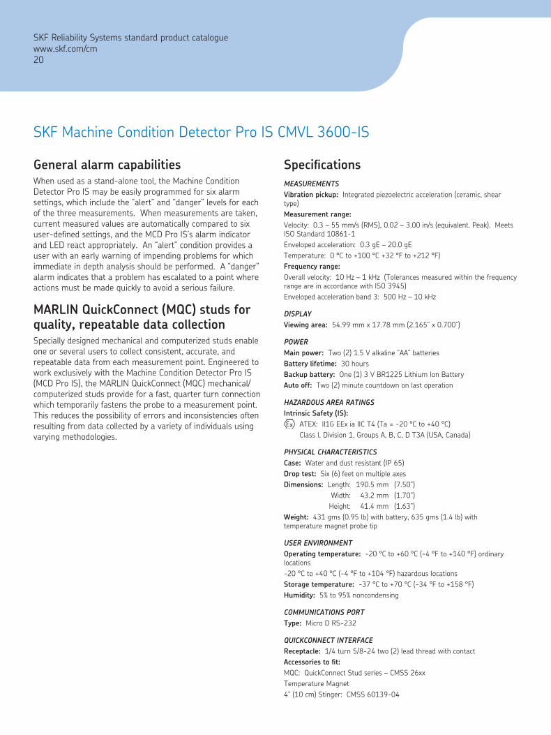
General alarm capabilitiesWhen used as a stand-alone tool, the Machine Condition Detector Pro IS may be easily programmed for six alarm settings, which include the “alert” and “danger” levels for each of the three measurements. When measurements are taken, current measured values are automatically compared to six user-defined settings, and the MCD Pro IS’s alarm indicator and LED react appropriately. An “alert” condition provides a user with an early warning of impending problems for which immediate in depth analysis should be performed. A “danger” alarm indicates that a problem has escalated to a point where actions must be made quickly to avoid a serious failure.
MARLIN QuickConnect (MQC) studs for quality, repeatable data collectionSpecially designed mechanical and computerized studs enable one or several users to collect consistent, accurate, and repeatable data from each measurement point. Engineered to work exclusively with the Machine Condition Detector Pro IS (MCD Pro IS), the MARLIN QuickConnect (MQC) mechanical/ computerized studs provide for a fast, quarter turn connection which temporarily fastens the probe to a measurement point. This reduces the possibility of errors and inconsistencies often resulting from data collected by a variety of individuals using varying methodologies.
SKF Machine Condition Detector Pro IS CMVL 3600-IS
SpecificationsMEASUrEMENTSVibration pickup: Integrated piezoelectric acceleration (ceramic, shear type)Measurement range:Velocity: 0.3 – 55 mm/s (RMS), 0.02 – 3.00 in/s (equivalent. Peak). Meets ISO Standard 10861-1Enveloped acceleration: 0.3 gE – 20.0 gETemperature: 0 °C to +100 °C +32 °F to +212 °F)Frequency range:Overall velocity: 10 Hz – 1 kHz (Tolerances measured within the frequency range are in accordance with ISO 3945)Enveloped acceleration band 3: 500 Hz – 10 kHz
DISPLAyViewing area: 54.99 mm x 17.78 mm (2.165” x 0.700”)
POwErMain power: Two (2) 1.5 V alkaline “AA” batteriesBattery lifetime: 30 hoursBackup battery: One (1) 3 V BR1225 Lithium Ion BatteryAuto off: Two (2) minute countdown on last operation
HAzArDOUS ArEA rATINGSIntrinsic Safety (IS):
ATEX: II1G EEx ia IIC T4 (Ta = -20 °C to +40 °C)Class I, Division 1, Groups A, B, C, D T3A (USA, Canada)
PHySICAL CHArACTErISTICSCase: Water and dust resistant (IP 65)Drop test: Six (6) feet on multiple axesDimensions: Length: 190.5 mm (7.50”) Width: 43.2 mm (1.70”) Height: 41.4 mm (1.63”)Weight: 431 gms (0.95 lb) with battery, 635 gms (1.4 lb) with temperature magnet probe tip
USEr ENVIrONMENTOperating temperature: -20 °C to +60 °C (-4 °F to +140 °F) ordinary locations-20 °C to +40 °C (-4 °F to +104 °F) hazardous locationsStorage temperature: -37 °C to +70 °C (-34 °F to +158 °F)Humidity: 5% to 95% noncondensing
COMMUNICATIONS POrTType: Micro D RS-232
QUICKCONNECT INTErFACEReceptacle: 1/4 turn 5/8-24 two (2) lead thread with contactAccessories to fit:MQC: QuickConnect Stud series – CMSS 26xxTemperature Magnet4” (10 cm) Stinger: CMSS 60139-04
SKF Reliability Systems standard product cataloguewww.skf.com/cm20

SKF Machine Condition Detector Pro IS CMVL 3600-IS
Ordering information
MCD Pro IS (Machine Condition Detector)CMVL 3600-IS-K-01-C Machine Condition Detector (MCD Pro IS) Kit
Each CMVL 3600-IS-K-01-C Kit consists of the following items:
MCD Pro IS (Machine Condition Detector) probe [CMVL 3600-IS]
MQC (MARLIN QuickConnect) 1/4-28 stud, one (1) [31706301]
Temperature magnet for MCD Pro IS (Machine Condition Detector) probe [CMAC 3610]
Stinger probe 4” (10 cm) [CMSS 60139-04]
“AA” Alkaline batteries, two (2)
MCD Pro IS (Machine Condition Detector) setup key [CMAC 3620]
MCD Pro IS (Machine Condition Detector) padded carrying Case [31736700]
MCD Pro IS (Machine Condition Detector) user manual [CMVL 3600M-SL]
MCD Pro IS (Machine Condition Detector) quick start card [CMVL 3600-QS]
MQC (MArLIN QuickConnect) and mounting accessories
MQC (MARLIN QuickConnect) mechanical M8 x 1.25 mounting thread – three (3) studs per package [CMSS 2600-3]
MQC (MARLIN QuickConnect) mechanical 1/4-28 mounting thread – three (3) studs per package [CMSS 2610-3]
MQC (MARLIN QuickConnect) computerized (patent pending) M8 x 1.25 mounting thread – three (3) studs per package [CMSS 2601-3]
MQC (MARLIN QuickConnect) computerized (patent pending) 1/4 x 28 mounting thread – three (3) studs per package [CMSS 2611-3]
Tool kit for spot face 1/4-28 [CMAC 9600-01]
Tool kit for spot face M8 x 1.25 [CMAC 9600-02]
Drill bit for 1/4-28 kit [CMAC 9600-03]
•
•
•
•
•
•
•
•
•
•
•
•
•
•
•
•
MQC (MArLIN QuickConnect) and mounting accessories (continued)
Tap for 1/4-28 kit [CMAC 9600-04]
Pilot for 1/4-28 kit [CMAC 9600-05]
Drill bit for M8 x 1.25 kit [CMAC 9600-06]
Tap for M8 x 1.25 kit [CMAC 9600-07]
Pilot for M8 x 1.25 kit [CMAC 9600-08]
End mill or counter bore for either kit [CMAC 9600-09]
Optional accessoriesCable, MDM (MARLIN I-Pro) to MCD Pro IS (Machine Condition Detector) [CMAC 6107]
MCD Pro IS (Machine Condition Detector) setup key [CMAC 3620]
Temperature magnet for MCD Pro IS (Machine Condition Detector) probe [CMAC 3610]
Probe tip replacement kit for temperature magnet for MCD Pro IS (Machine Condition Detector) [CMAC 3630]
Magnetic probe tip for MCD Pro IS (Machine Condition Detector) [CMAC 3611]
Stinger probe 4” (10 cm) [CMSS 60139-04]
1/4-28 MQC (MARLIN QuickConnect) for stinger interface [CMSS 2610-1]
MCD Pro IS (Machine Condition Detector) quick start card [CMVL 3600-QS]
MCD Pro IS (Machine Condition Detector) user manual [CMVL 3600M-SL]
MArLIN data managerThe MARLIN MCD Pro IS can be used in non-hazardous conditions with the following MARLIN data managers as well as all international language translation kits:
MARLIN I-Pro CS, Bar Code Scanner [CMDM 6210]
MARLIN I-Pro NI2, Bar Code Imager, NI (Non-incendive) Class I Division 2 [CMDM 6220]
MARLIN I-Pro NIA, Bar Code Imager, NI (Non-incendive) ATEX Zone 2 [CMDM 6230]
MARLIN I-Pro IS data manager, Class I, Division 1, Groups C and D [CMDM 6350]
MARLIN S-Pro IS data manager, ATEX Zone 1 [CMDM 5360]
•
•
•
•
•
•
•
•
•
•
•
•
•
•
•
•
•
•
•
•
SKF Reliability Systems standard product cataloguewww.skf.com/cm
21

Now available in multiple languages (ML): English, Chinese, German and Spanish.
With SKF’s new MicroVibe P, vibration assessment is as close and convenient as your PDA! This economical vibration meter expansion module fits in a PocketPC’s compact flash card slot (CF Type II) and features the user-friendly Windows® Mobile Operating System. Identify problems and assess machine condition quickly and easily with this versatile and easy-to-use pocket tool.
Power without complexityA handy “quick-check” solution, based on the universal PDA platform, MicroVibe P is simple to use. Built-in automatic functions virtually eliminate setup, while the analytical displays and automatic judgment of machine vibration readings help users identify machine problems on the spot!
FeaturesExceptional value
Low cost, compact, lightweight, works with many Pocket PC PDA’s by Hewlett-Packard, Dell, Toshiba, etc.
Quickly identify problems
Expert judgment criteria based on ISO vibration severity standard and SKF bearing evaluation
•
–
•
–
The SKF MicroVibe P system
FFT Spectrum analysis enables user to pinpoint problems like unbalance, misalignment, bearing, rubs, etc.
Multi-point automation
Standard vibration measurements
Envelope acceleration, acceleration, velocity, displacement, time waveform, and FFT spectrum analysis
Store and recall measurements
For trending and analysis, store up to 2,000 overall vibration signals, 1,000 FFT spectrum, and 200 time waveforms
Data management software
Enables users to transfer machinery vibration data to a computer for trending and further analysis
MicroVibe P kit includes:
MicroVibe P module, data management software, accelerometer and cable, magnetic base, earphones, user manual, and carrying case (everything but the PDA).
An advanced instrument for simplified vibration assessmentThe MicroVibe P collects and displays overall vibration readings and automatically provides expert judgment of the measured velocity and overall enveloped acceleration levels, enabling immediate, accurate and reliable assessment of machine or bearing condition.
–
–
•
–
•
–
•
–
•
–
SKF MicroVibe PCMVL 3850-MLPower without complexity, an advanced instrument for simplified vibration assessment that fits in your pocket.
SKF Reliability Systems standard product cataloguewww.skf.com/cm22
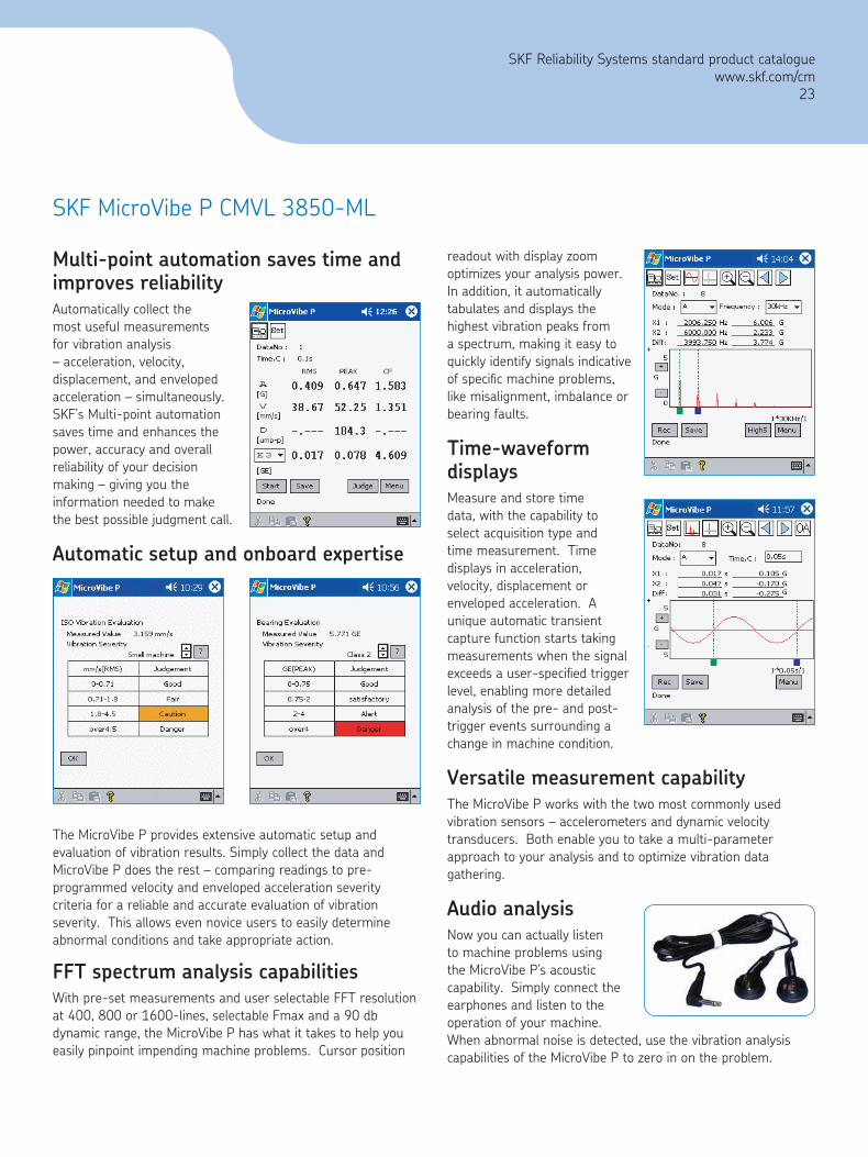
Multi-point automation saves time and improves reliabilityAutomatically collect the most useful measurements for vibration analysis – acceleration, velocity, displacement, and enveloped acceleration – simultaneously. SKF’s Multi-point automation
saves time and enhances the power, accuracy and overall reliability of your decision making – giving you the information needed to make the best possible judgment call.
Automatic setup and onboard expertise
The MicroVibe P provides extensive automatic setup and evaluation of vibration results. Simply collect the data and MicroVibe P does the rest – comparing readings to pre-programmed velocity and enveloped acceleration severity criteria for a reliable and accurate evaluation of vibration severity. This allows even novice users to easily determine abnormal conditions and take appropriate action.
FFT spectrum analysis capabilitiesWith pre-set measurements and user selectable FFT resolution at 400, 800 or 1600-lines, selectable Fmax and a 90 db dynamic range, the MicroVibe P has what it takes to help you easily pinpoint impending machine problems. Cursor position
readout with display zoom optimizes your analysis power. In addition, it automatically tabulates and displays the highest vibration peaks from a spectrum, making it easy to quickly identify signals indicative of specific machine problems, like misalignment, imbalance or bearing faults.
Time-waveform displaysMeasure and store time data, with the capability to select acquisition type and time measurement. Time displays in acceleration, velocity, displacement or enveloped acceleration. A unique automatic transient capture function starts taking measurements when the signal exceeds a user-specified trigger level, enabling more detailed analysis of the pre- and post-trigger events surrounding a change in machine condition.
Versatile measurement capability The MicroVibe P works with the two most commonly used vibration sensors – accelerometers and dynamic velocity transducers. Both enable you to take a multi-parameter approach to your analysis and to optimize vibration data gathering.
Audio analysisNow you can actually listen to machine problems using the MicroVibe P’s acoustic capability. Simply connect the earphones and listen to the operation of your machine. When abnormal noise is detected, use the vibration analysis capabilities of the MicroVibe P to zero in on the problem.
SKF MicroVibe P CMVL 3850-ML
SKF Reliability Systems standard product catalogue www.skf.com/cm
23

_
1.5 m(5 ft)
40 mm(1.57 in)
20 mm(0.79 in)
Store and recall measurements for trending and analysisThe MicroVibe P’s data storage capacity is also extraordinarily impressive. It can store up to 2,000 overall vibration signals, 1,000 FFT spectrums or 200 records of time waveform data for later recall. A search function retrieves specific measurement points and a “repeat” measurement let’s you recall and repeat any measurement for more focused analysis or trending of a potential problem. Finally, a “recall data storage” list helps you keep track of and reference all collected data.
Data management and software for your desktop computerThe MicroVibe P offers added functionality, including a software program to extract, save, edit and display collected data. It’s ideal for small route data collection.
For further analysis and trending, data may be uploaded to your desktop computer using the Data Management software. Once uploaded, vibration data, overall trends and spectra can be stored, trended, graphically displayed and even exported to Excel®.
Utilities add valueSeveral exciting utilities help make the MicroVibe P an universal tool for machine vibration analysis, for any level of expertise. Collect data in english or metric units or reference a dictionary of vibration terminology.
SKF’s new MicroVibe P truly brings you vibration monitoring and analysis power without complexity. It’s tomorrow’s big solution for vibration analysis in a small, smart package – and its available today! Get more information at www.skf.com/cm.
Specifications MicroVibe P CMVL 3850-MLMinimum PDA requirements(*): Conforms to the Pocket PC specificationsOperating system: Microsoft® Windows® Mobile 3.0/5.0Processor: ARM processorInterface: Compact Flash TYPE II Slot 3.3 V onlyRecommended specifications:Processor: PXA255 400 MHz or higherMemory (RAM): 64 MB or higherInterface with Pocket PC: Compact Flash TYPE II, slot 3.3 V onlyPower supply: +3.3 V (supplied by Pocket PC)Current:Standby: 44 µ AUnder measurement: 48 mAPickup input (PU IN):AC voltage signal: Maximum ± 2.5 VInput terminal: 8-pin modular jack (RJ-45) (ICP type pre-amp built-in accelerometer is not connected.Raw waveform output (PU OUT):AC voltage signal: Maximum ± 2.5 VOutput terminal: Mini-jack (2.5 mm F)Sampling frequency: Maximum 76.8 kHz (changes according to mode) 76.8 kHz/38.4 kHzAliasing filter: 20 kHz/2 kHz (changes according to mode and sampling frequency)A/D: 16-BitTemperature range: 0 to +45 °C (+32 °F to +113 °F)Humidity range: <90% relative humidity, non-condensingWeight: 25 g (0.88 oz) approximate (Card only)Dimensions: 60.0 mm x 42.1 mm x 16.9 mm (2.36” x 1.66” x 0.67”)Shape: Conforms to CF Card TYPE II, Card Type. See photograph.Color: Black
* May not work with all PDA’s. Please see list of Certified PDA’s.
CMSS 3811 AccelerometerType: Pre-amp is built-in. Shear type.Power supply: DC ± 5 VVoltage sensitivity: 20 mV/gResonance frequency: 20 kHz approximateFrequency range: 3 Hz to 10,000 HzMaximum acceleration: 500 m/s2
Vibration limit: 5000 m/s2
Maximum output voltage: ± 1 VOutput impedance: Below 100 ΩTemperature range: -20 °C to +80 °C (-4 °F to +176 °F)Material: SUSWeight: 60 g (2.1 oz) approximateTapped hole: M6, P = 1, depth 5 mm, internal threadIntegral cable: Length 1.5 meters (5 feet)Connector: 8-pin modular plugDimensions: See drawing belowStructure: Dust-proof, spray-proof
CMSS 3811Accelerometer Dimensions
SKF MicroVibe P CMVL 3850-ML
SKF Reliability Systems standard product cataloguewww.skf.com/cm24
Ordering InformationMicroVibe P Kit CMVL 3850-ML includes:
MicroVibe P ModuleCMSS 3811 Accelerometer, 1.5 meters (5 feet) integral cable, with plug, and stinger one (1) eachCMAC 3825 Two-Bar Magnetic Base, high strength 35 lb pull, one (1) eachCMAC 3830 Earphones, one (1) eachData Management software CD-ROM, one (1) eachMicroVibe P documentation (English and German)
User manual (PDF)Data management software manual (PDF)Quick start guide (PDF)CE declaration of confirmation
Carrying case
NOTE: Pocket PC (PDA) NOT INCLUDED.
Additional AccessoriesCMSS 3811 Accelerometer, 1.5 meters (5 feet) integral cable (replacement), with plug, and stinger, one (1) eachCMSS 3812 Velocity Pickup Sensor, 1.5 meters (5 feet) integral cable, with plug, one (1) eachCMAC 3825 Two-Bar Magnetic Base, high strength 40 lb pull, one (1) eachCMAC 3830 Earphones, one (1) each
Certified Pocket PC PDA’s with Windows Mobile™ 2003/2005Certified Pocket PC PDA’s with windows Mobile™ 2003
Hewlett PackardiPAQ hx2400iPAQ hx2700iPAQ hx2750iPAQ hx4700
Toshibae830
ASUS MyPal A730Dell AXIM X50 (NOT 51)
Compatible Pocket PC PDA’s with windows Mobile™ 2003
Hewlett PackardiPAQ h2210iPAQ h2215
Toshibae800
Certified Pocket PC PDA’s with windows Mobile™ 2005
Hewlett PackardiPAQ hx2490iPAQ hx2790
••
•
••
•
––––
•
•
•
•
•
•––––
•–
••
•––
•–
•––
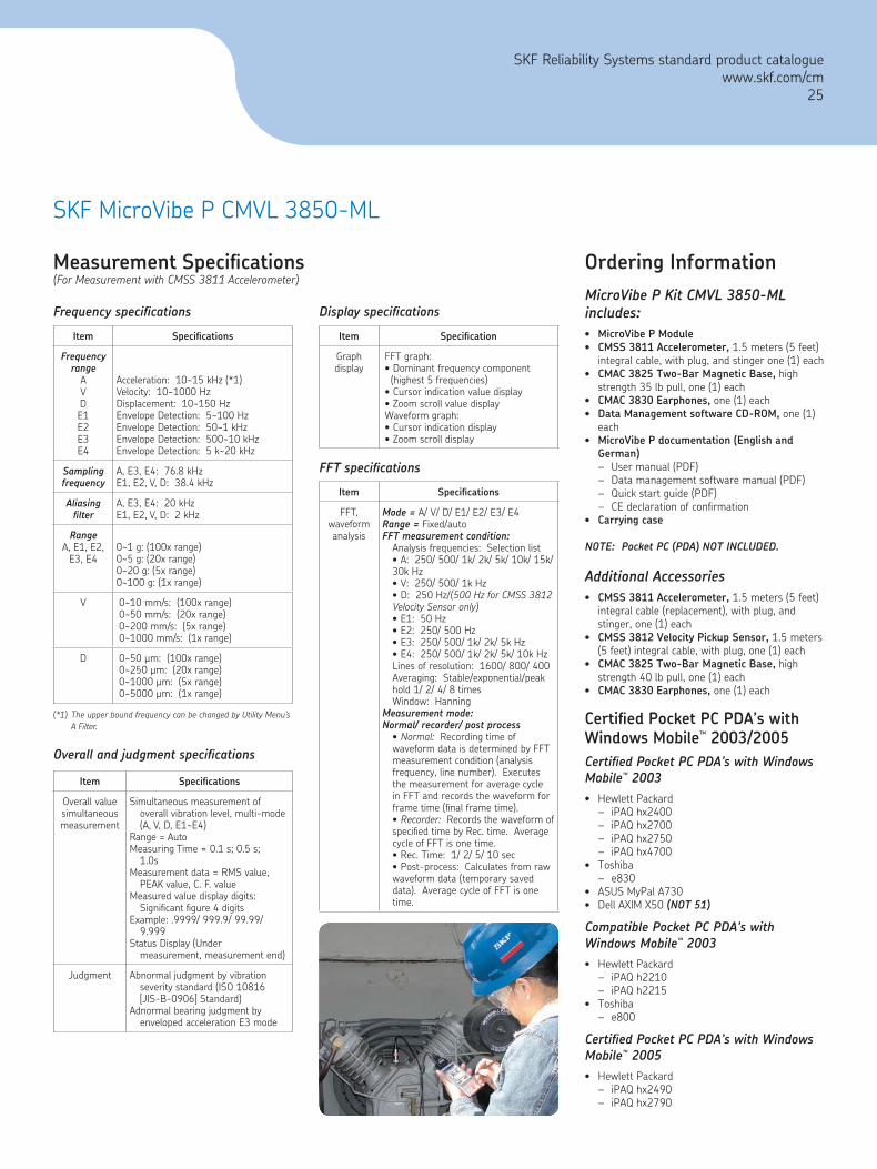
Frequency specifications
FFT specifications
Measurement Specifications(For Measurement with CMSS 3811 Accelerometer)
(*1) The upper bound frequency can be changed by Utility Menu’s A Filter.
Overall and judgment specifications
Display specifications
Item Specifications
Frequency range
AVDE1E2E3E4
Acceleration: 10~15 kHz (*1)Velocity: 10~1000 HzDisplacement: 10~150 HzEnvelope Detection: 5~100 HzEnvelope Detection: 50~1 kHzEnvelope Detection: 500~10 kHzEnvelope Detection: 5 k~20 kHz
Sampling frequency
A, E3, E4: 76.8 kHzE1, E2, V, D: 38.4 kHz
Aliasing filter
A, E3, E4: 20 kHzE1, E2, V, D: 2 kHz
rangeA, E1, E2,
E3, E40~1 g: (100x range)0~5 g: (20x range)0~20 g: (5x range)0~100 g: (1x range)
V 0~10 mm/s: (100x range)0~50 mm/s: (20x range)0~200 mm/s: (5x range)0~1000 mm/s: (1x range)
D 0~50 µm: (100x range)0~250 µm: (20x range)0~1000 µm: (5x range)0~5000 µm: (1x range)
Item Specifications
Overall valuesimultaneousmeasurement
Simultaneous measurement ofoverall vibration level, multi-mode (A, V, D, E1~E4)
Range = AutoMeasuring Time = 0.1 s; 0.5 s;
1.0sMeasurement data = RMS value,
PEAK value, C. F. valueMeasured value display digits:
Significant figure 4 digitsExample: .9999/ 999.9/ 99.99/
9.999Status Display (Under
measurement, measurement end)
Judgment Abnormal judgment by vibrationseverity standard (ISO 10816[JIS-B-0906] Standard)
Adnormal bearing judgment byenveloped acceleration E3 mode
Item Specification
Graph display
FFT graph:• Dominant frequency component (highest 5 frequencies)
• Cursor indication value display• Zoom scroll value displayWaveform graph:• Cursor indication display• Zoom scroll display
Item Specifications
FFT,waveform analysis
Mode = A/ V/ D/ E1/ E2/ E3/ E4range = Fixed/autoFFT measurement condition:
Analysis frequencies: Selection list• A: 250/ 500/ 1k/ 2k/ 5k/ 10k/ 15k/ 30k Hz• V: 250/ 500/ 1k Hz• D: 250 Hz/(500 Hz for CMSS 3812 Velocity Sensor only)• E1: 50 Hz• E2: 250/ 500 Hz• E3: 250/ 500/ 1k/ 2k/ 5k Hz• E4: 250/ 500/ 1k/ 2k/ 5k/ 10k HzLines of resolution: 1600/ 800/ 400Averaging: Stable/exponential/peak hold 1/ 2/ 4/ 8 timesWindow: Hanning
Measurement mode:Normal/ recorder/ post process
• Normal: Recording time of waveform data is determined by FFT measurement condition (analysis frequency, line number). Executes the measurement for average cycle in FFT and records the waveform for frame time (final frame time).• Recorder: Records the waveform of specified time by Rec. time. Average cycle of FFT is one time.• Rec. Time: 1/ 2/ 5/ 10 sec• Post-process: Calculates from raw waveform data (temporary saved data). Average cycle of FFT is one time.
SKF MicroVibe P CMVL 3850-ML
SKF Reliability Systems standard product cataloguewww.skf.com/cm
25
ENVIrONMENTALOperating temperature: -20 °C to +80 °C (-4 °F to +176 °F)Sealed: Epoxy encapsulatedEnclosure: SS, NEMA 4, 4X, 12Mounting: Stud mountedWeight (without display): 227 g (8 oz.)
rEGULATOry APPrOVALCE Mark: SKF Loop-Powered Vibration Transmitter CMSS 420VT and displays CMSS 420LCD and CMSS 420LED
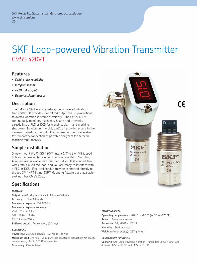
FeaturesSolid-state reliability
Integral sensor
4-20 mA output
Dynamic signal output
DescriptionThe CMSS 420VT is a solid-state, loop-powered vibration transmitter. It provides a 4-20 mA output that is proportional to overall vibration in terms of velocity. The CMSS 420VT continuously monitors machinery health and transmits directly into a PLC or DCS for trending, alarm and machine shutdown. In addition, the CMSS 420VT provides access to the dynamic transducer output. The buffered output is available for temporary connection of portable analyzers for detailed machine fault analysis.
Simple installationSimply mount the CMSS 420VT into a 1/4”-28 or M8 tapped hole in the bearing housing or machine case (NPT Mounting Adapters are available, part number CMSS 203), connect two wires into a 4-20 mA loop, and you are ready to interface with a PLC or DCS. Electrical conduit may be connected directly to the top 3/4” NPT fitting, (NPT Mounting Adapters are available, part number CMSS 203).
SpecificationsDyNAMICOutput: 4-20 mA proportional to full scale VelocityAccuracy: ± 5% of full-scaleFrequency response: 2-2,000 HzFrequency response accuracy:-3 db: 2 Hz to 2 kHz10%: 10 Hz to 1 kHz5%: 15 Hz to 750 HzBuffered output: Acceleration, 100 mV/g
ELECTrICALPower (Two wire loop power): +22 Vdc to +36 VdcMaximum load (see note – maximum load resistance calculations for specific requirements): Up to 600 Ohms resistive Grounding: Case isolated
•
•
•
•
SKF Loop-powered Vibration TransmitterCMSS 420VT
SKF Reliability Systems standard product cataloguewww.skf.com/cm26

CMSS 420EL – 90 Degree 3/4” by 3/4” NPT Elbow
Useful for connecting CMSS 420VT to hard or flexible conduit. When used with the CMSS 420WF, provides a simple weatherproof exit for the instrument wire.
CMSS 203 – Pipe Thread Accelerometer Mounting Adapter
They are provided in several NPT sizes to accommodate the most common plugs found on most machinery. The adapters have a 1/4”-28 threaded hole to mate with the CMSS 420VT and most common accelerometers and vibration transmitters.
Part number Pipe thread mounting adapter
CMSS 203-01 1/2” (NPT) National pipe tapered thread
CMSS 203-02 3/4” (NPT) National pipe tapered thread
CMSS 203-03 3/8” (NPT) National pipe tapered thread
CMSS 203-04 1/4” (NPT) National pipe tapered thread
AccessoriesCMSS 420LCD/CMSS 420LED Display Retrofit (requires transmitter)
LCD displays actual vibration levels in velocity on a Liquid Crystal display. LED displays actual vibration levels in velocity on a Light Emitting Diode display. The displays are shipped loose, and it is a simple installation. Includes a BNC connector that provides access to the raw acceleration signal.
CMSS 420BNC – BNC Adapter Retrofit – BNC Adapter RetrofitBNC Adapter Retrofit
90 Degree 3/4” NPT conduit elbow with a BNC connector to access the raw acceleration signal. This is useful for connection to portable data collectors.
CMSS 420WF – 3/4” NPT Weatherproof Cable Fitting
When used with the CMSS 420EL, provides a simple weatherproof exit for the instrument wire.
Optional display
Light Emitting Diode Display (LED) Liquid Crystal Display (LCD)
CMSS 420LED-01 0-1 in/sec. CMSS 420LCD-01 0-1 in/sec.
CMSS 420LED-02 0-2 in/sec. CMSS 420LCD-02 0-2 in/sec.
CMSS 420LED-51 25.4 mm/sec. CMSS 420LCD-51 25.4 mm/sec.
CMSS 420LED-52 50.8 mm/sec. CMSS 420LCD-52 50.8 mm/sec.
SKF Loop-powered Vibration Transmitter CMSS 420VT
Ordering informationCMSS 420VT-1 25.4 mm/sec. (0-1 in/sec.) RMS, includes 1/4”-28 and M8 Mounting Studs
CMSS 420VT-2 50.8 mm/sec. (0-2 in/sec.) RMS, includes 1/4”-28 and M8 Mounting Studs
NOTE: Maximum load resistance calculations: RLoad = (Vs - 13.5 - Vd) / 0.032where: RLoad = Load Resistance Vs = DC Supply Voltage Vd = Display Voltage (5.0 Vdc for LED, 2.0 Vdc for LCD, 0 Vdc if not using a display unit)For Example:Using a LED Display and a Supply Voltage of 24 VdcSupply Voltage Vs = 24 V; Display Voltage Vd = 5.0 Vdc for LED RLoad = (Vs - 13.5 V - Vd) / 0.032 = (24 V - 13.5 V - 5 Vdc) / 0.032 = 172 Ohm
SKF Reliability Systems standard product cataloguewww.skf.com/cm
27

For additional information on SKF Reliability Systems products, contact:
SKF Reliability Systems5271 Viewridge Court • San Diego, California 92123 USATelephone: +1 858-496-3400 • FAX: +1 858-496-3531
web Site: www.skf.com/cmThe contents of this publication are the copyright of the publisher and may not be reproduced (even extracts) unless permission is granted. Every care has been taken to ensure the accuracy of the information contained in this publication but no liability can be accepted for any loss or damage whether direct, indirect or consequential arising out of the use of the information contained herein. SKF reserves the right to alter any part of this publication without prior notice.
SKF Patents include: #US05854553, #US05845230, #US06489884, #US05679900, #US04768380, #US06199422, #US05992237, #US06202491, #US06513386, #US06275781, #US06633822, #US06006164, #US2003_0178515A1, #US6,789,025, #US6,789,360, US 5,633,811 and US 5,870,699, #WO_03_048714A1
SKF, Microlog and MARLIN are registered trademarks of the SKF Group.Microsoft, Windows and Excel are registered trademarks and Windows Mobile is a trademark of Microsoft Corporation.All other trademarks are the property of their respective owners.
CM2355 (6-07) • Copyright © 2007 by SKF Condition Monitoring, Inc. ALL RIGHTS RESERVED
••
•
SKF Reliability Systems standard product catalogue
Product Support Plan (PSP)A range of Product Support Plans are available to protect your investment. Contact your local SKF Reliability Systems Sales Representative for additional information.


