28
Version 4.3 SL-125 Series & SL-125 Complete 5-9NM+ LED Marine Lantern Installation & Service Manual

Version 4.3
SL-125 Series & SL-125 Complete5-9NM+ LED Marine LanternInstallation & Service Manual

SL-125 Series5-9NM+ LED Marine Lantern
SL-125 Complete5-9NM+ Complete Marine Lantern Assembly
Models shown with optional 2nd solar module
SL-125/C-Type 2
SL-125/C Type 1
LED lens and Sealite’s 360o Omnidirectional
LED Reflector (US Pat. No. 6,667,582. AU Pat. No. 778,918)
Bird deterrent spike
Automatic night activation
Large industry standard 200mm OD base
pattern
Lens and base moulded from UV-stabilised
LEXAN® polycarbonate (IP68 rating)
Adjustable solar module(s) angled to maximise solar
collection
LED lens and Sealite’s 360o Omnidirectional
LED Reflector (US Pat. No. 6,667,582. AU Pat. No. 778,918)
Lens moulded from UV-stabilised LEXAN®
polycarbonate (IP68 rating)
Large user-replaceable 55Ah battery in 7-stage
powder-coated aluminium housing
Large industry standard 200mm OD base pattern
Bird deterrent spike

Latest products and information available at www.sealite.com3
SL-125 Series 5-9NM+ LED Marine Lantern
Table of Contents
Introduction ..........................................................................................Page 4
Operating Principle .............................................................................Page 4
Technology ...........................................................................................Page 4
SL-125 & SL-125-C Models .................................................................Page 5 SL-125 Series..............................................................................Page 6 SL-125CompleteAvailableConfigurations .................................Page 8 SL-125 Type 1 Complete .............................................................Page 9 SL-125 Type 2 Complete ...........................................................Page 10
Optional Configurations ...................................................................Page 12
Installation ..........................................................................................Page 13
Selecting an Intensity/Power Setting...............................................Page 14
Selecting a Flash Code .....................................................................Page 14
RF Synchronisation (Comm-Sync) Option .....................................Page 15
GPS Synchronisation Option ...........................................................Page 16
Lantern Status ...................................................................................Page 17
Flash Codes .......................................................................................Page 19
Maintenance and Servicing ..............................................................Page 24
Trouble Shooting ...............................................................................Page 25
Sealite Lantern Warranty ..................................................................Page 26
Version No. Description Date Approved3.1 Update Manual May 2010 A. Dixon3.2 Logo Update August 2010 K. Paton4.0 Update: Quality Logo May 2011 J. Dore4.1 Update: Spec Tables May 2012 J. Dore4.2 GPS info update July 2012 J. Dore4.3 Spec table update February 2015 J. Dore

Latest products and information available at www.sealite.com4
SL-125 Series 5-9NM+ LED Marine Lantern
The solar module of the lantern converts sunlight to an electrical current that is used to charge the battery (SL-125-C models only). The battery provides power to operate the lantern at night. Theflasherunithasverylowcurrentrequirements.AmicroprocessordrivesanarrayofultrabrightLED’sthroughaDC/DCconverter,whichenablestheLED’stooperatewithinthemanufacturer’sspecifications.Thebattery is protected from over-charging within the circuit to ensure maximum battery life. Ondarkness,themicroprocessorwillinitiateaprogramcheckandafterapproximately1minutebeginflashingto the set code
IntroductionCongratulations! By choosing to purchase a Sealite lantern you have become the owner of one of the most advanced LED marine lanterns in the world.Sealite Pty Ltd has been manufacturing lanterns for over 25 years, and particular care has been taken to ensure your lantern gives years of service.Asacommitmenttoproducingthehighestqualityproductsforourcustomers,SealitehasbeenindependentlycertifiedascomplyingwiththerequirementsofISO9001:2008qualitymanagementsystem.SealitelanternscomplywithrequirementsoftheUSCoastGuardin33CFRpart66forPrivateAidsToNavigation.By taking a few moments to browse through this booklet, you will become familiar with the versatility of your lantern, and be able to maximise its operating function.
Operating Principle
TechnologySealite is the world’s fastest growing manufacturer of marine aids to navigation. We employ leading mechanical, optical, hardware & software engineers to create innovative products to service the needs of our customers worldwide, and offer the widest range of solar-powered LED lanterns in the marketplace. ElectronicsSealite employs leading in-house electronic engineers in the design and development of software and related circuitry. All individual electronic components are sourced directly by Sealite procurement staff ensuring that onlythehighestqualitycomponentsareusedinourproducts.
LED TechnologyAllmarinelanternsusethelatestadvancementsinLED(LightEmittingDiode)technologyasalightsource.ThemajoradvantageofLED’sovertraditionallightsourcesiswellestablishedinthattheytypicallyhaveanoperational life in excess of 100,000 hours, resulting in substantial savings to maintenance and servicing costs.
Precision Construction Commitment to investing in the design and construction of injection-moulded parts including optic lenses, light basesandarangeofothercomponentsensuresthatallSealiteproductsareofaconsistent&superiorquality.
Optical PerformanceSealitemanufacturesarangeofmarineLEDlensesmouldedfrommulti-cavitydies.ComplexshapessuchastheSL70,BargeSafe™and16-segmentmulti-focuslensesareatestamenttothecompany’ssuperior in-house lens manufacturing capabilities and outstanding optical performance.
Award-winning, Patented Technology SeveralUnitedStatesandAustralianpatentregistrationsareheldonSealite’srangeofinnovativedesigns,withotherregionalpatentspendinginCanada,UnitedKingdomandEurope.

Latest products and information available at www.sealite.com5
SL-125 Series 5-9NM+ LED Marine Lantern
SL-125 & SL-125-C ModelsThe SL-125 5-9NM+ light fixture is the most advanced LED marine lantern on the market. Utilising the latest software and micro circuitry developments, the lantern boasts a huge number of features including flash-memory and the most efficient power conversion available. This maintenance-free model is also available with up to 4 tiers of 36 LEDs to increase the light intensity for a range of different light colours (see Specifications table below). Each LED tier utilises the Sealite omnidirectional LED Reflector (US Pat. No. 6,667,582. AU Pat. No. 778, 918) to increase the intensity and uniformity of the horizontal output. In particular, the SL-125 4-tier model utilises a unique heat-dissipating domed lens to achieve maximum LED intensity output over a wider range of environmental conditions. The SL-125-C Complete Lantern Assembly provides a complete solution for visual navigation requirements incorporating solar modules and battery to power the light.Remote monitoring and control capabilities are also available for the SL-125, allowing the performance of the units to be monitored from remote sites. System status includes battery condition, flash characters, operational configuration, and lantern/buoy position. The SL-125 may also be fitted with Comm-Sync. The Sealite Comm-Sync range of lanterns utilises an internal RF module that operates on a 2.4Ghz frequency and has an operational range of up to 1.4km between 2 lights. Should more than two lights be required to be synchronised the range may be extended for longer distances as the lanterns transmit data to the adjacent lantern, causing it to fall in to synchronisation. The only limitation is no lantern should be more than 1.4km from the next lantern in series.
Table 1.1. SL-125 LED Marine Lantern Series (12v)
Model Description
Peak IntensityFlashing
(cd) Colour No. LEDsPower
Amp/hour Voltage
SL-125-1.RSL-125-1.GSL-125-1.WSL-125-1.Y
1-tierLEDLantern
163200180145
RedGreen White Yellow
36363636
0.420.320.320.42
12v12v12v12v
SL-125-2.RSL-125-2.GSL-125-2.WSL-125-2.Y
2-tierLEDLantern
280328319257
RedGreen White Yellow
72727272
0.840.640.640.84
12v12v12v12v
SL-125-3.RSL-125-3.GSL-125-3.WSL-125-3.Y
3-tierLEDLantern
427518496399
RedGreen White Yellow
108108108108
1.280.960.961.28
12v12v12v12v
SL-125-4.RSL-125-4.GSL-125-4.WSL-125-4.Y
4-tierLEDLantern
7981010940760
RedGreen White Yellow
144144144144
1.701.281.281.70
12v12v12v12v
Subject to change or variation without notice
Latest products and information available at www.sealite.com6
SL-125 Series 5-9NM+ LED Marine Lantern
SL-125 Series
• Sp
ec
ifica
tion
s sub
jec
t to c
ha
ng
e o
r varia
tion
with
ou
t no
tice
* Su
bje
ct to
stan
da
rd te
rms a
nd
co
nd
ition
s†
Inte
nsity se
tting
sub
jec
t to so
lar a
vaila
bility
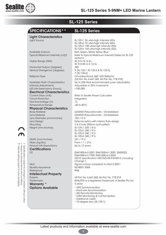
SPECIFICATIONS•* SL-125 SeriesLight CharacteristicsLight Source SL-125-1: 36 ultra-high intensity LEDs
SL-125-2: 72 ultra-high intensity LEDsSL-125-3: 108 ultra-high intensity LEDsSL-125-4: 144 ultra-high intensity LEDs
Available Colours Red, Green, White, Yellow, BlueTypical Maximum Intensity (cd)† Refer to Typical Maximum Intensity Tables for SL-125
lanternsVisible Range (NM) AT @ 0.74: 5–9+
AT @ 0.85: 6.3–12.5+Horizontal Output (degrees) 360Vertical Divergence (degrees) 9 (SL-125-1, SL-125-2 & SL-125-3)
7 (SL-125-4)Reflector Type Omnidirectional 360° LED Reflector
(US Pat. No. 6,667,582. AU Pat. No. 778,918)Available Flash Characteristics Up to 256 IALA recommended (user adjustable)Intensity Adjustments Adjustable in 25% incrementsLED Life Expectancy (hours) >100,000
Electrical CharacteristicsCurrent Draw (mA) Refer to Sealite Power CalculatorCircuit Protection IntegratedNominal Voltage (V) 12Temperature Range -40 to 80°C
Physical CharacteristicsBody Material LEXAN® Polycarbonate – UV-stabilisedLens Material LEXAN® Polycarbonate – UV-stabilisedLens Diameter (mm/inches) 150 / 57/8
Lens Design External optics with interior flute designMounting 3 & 4 hole 200mm bolt patternHeight (mm/inches) SL-125-1: 205 / 81/8
SL-125-2: 240 / 91/2
SL-125-3: 240 / 91/2
SL-125-4: 240 / 91/2
Width (mm/inches) 231 / 91/8
Mass (kg/lbs) From 1.1 / 23/8 Product Life Expectancy Up to 12 years
CertificationsCE EN61000-6-3:2001. EN61000-6-1:2001. EN55022.
EN61000-4-2:1995. EN61000-4-3:2002USCG specification HSCG23-05-R-E43013, including Change 1.
IALA Signal colours compliant to IALA E-200-1Quality Assurance ISO9001:2008Waterproof IP68
Intellectual PropertyPatents US Pat. No. 6,667,582. AU Pat. No. 778,918Trademarks SEALITE® is a registered trademark of Sealite Pty Ltd
Warranty * 3 years
Options Available • GPS Synchronisation • Hard-wire Synchronisation• AIS Remote Monitoring • GSM Monitoring & Control System • Additional cable• 10 degree lens (SL-125-1)

Latest products and information available at www.sealite.com7
SL-125 Series 5-9NM+ LED Marine Lantern
Figure 1.1. SL-125-1
Figure 1.3. SL-125-4
Figure 1.2. SL-125-2 & SL-125-3
Figure 1.4. Base (all models)
Latest products and information available at www.sealite.com8
SL-125 Series 5-9NM+ LED Marine Lantern
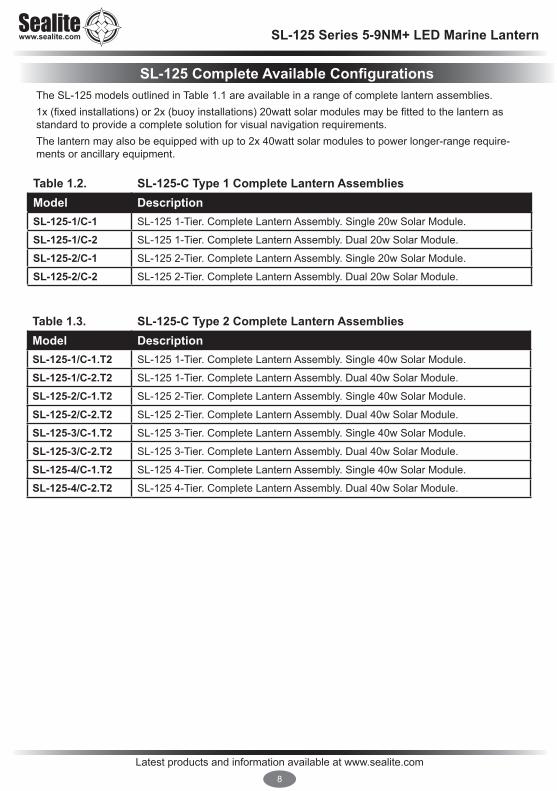
The SL-125 models outlined in Table 1.1 are available in a range of complete lantern assemblies. 1x(fixedinstallations)or2x(buoyinstallations)20wattsolarmodulesmaybefittedtothelanternasstandardtoprovideacompletesolutionforvisualnavigationrequirements.Thelanternmayalsobeequippedwithupto2x40wattsolarmodulestopowerlonger-rangerequire-mentsorancillaryequipment.
Table 1.2. SL-125-C Type 1 Complete Lantern AssembliesModel DescriptionSL-125-1/C-1 SL-125 1-Tier. Complete Lantern Assembly. Single 20w Solar Module.
SL-125-1/C-2 SL-125 1-Tier. Complete Lantern Assembly. Dual 20w Solar Module.
SL-125-2/C-1 SL-125 2-Tier. Complete Lantern Assembly. Single 20w Solar Module.
SL-125-2/C-2 SL-125 2-Tier. Complete Lantern Assembly. Dual 20w Solar Module.
Table 1.3. SL-125-C Type 2 Complete Lantern AssembliesModel DescriptionSL-125-1/C-1.T2 SL-125 1-Tier. Complete Lantern Assembly. Single 40w Solar Module.
SL-125-1/C-2.T2 SL-125 1-Tier. Complete Lantern Assembly. Dual 40w Solar Module.
SL-125-2/C-1.T2 SL-125 2-Tier. Complete Lantern Assembly. Single 40w Solar Module.
SL-125-2/C-2.T2 SL-125 2-Tier. Complete Lantern Assembly. Dual 40w Solar Module.
SL-125-3/C-1.T2 SL-125 3-Tier. Complete Lantern Assembly. Single 40w Solar Module.
SL-125-3/C-2.T2 SL-125 3-Tier. Complete Lantern Assembly. Dual 40w Solar Module.
SL-125-4/C-1.T2 SL-125 4-Tier. Complete Lantern Assembly. Single 40w Solar Module.
SL-125-4/C-2.T2 SL-125 4-Tier. Complete Lantern Assembly. Dual 40w Solar Module.
SL-125 Complete Available Configurations

Latest products and information available at www.sealite.com9
SL-125 Series 5-9NM+ LED Marine Lantern
SL-125 Type 1 Complete
• S
pe
cifi
ca
tion
s su
bje
ct t
o c
ha
ng
e o
r va
riatio
n w
itho
ut n
otic
e
* Su
bje
ct t
o s
tan
da
rd te
rms
an
d c
on
diti
on
s†
Inte
nsi
ty s
ett
ing
su
bje
ct t
o s
ola
r ava
ilab
ility
• Specifications subject to change or variation without notice
* Subject to standard terms and conditions† Intensity setting subject to solar availability
SPECIFICATIONS•* SL-125-C Type 1Light CharacteristicsLight Source SL-125-1 or SL-125-2Available Colours Red, Green, White, Yellow, BlueTypical Maximum Intensity (cd)† Refer to Typical Maximum Intensity Table for SL-125-1 or SL-125-2Visible Range (NM) AT @ 0.74: 5–7+
AT @ 0.85: 6.3–9.3+Horizontal Output (degrees) 360Vertical Divergence (degrees) 9Reflector Type Omnidirectional 360° LED Reflector
(US Pat. No. 6,667,582. AU Pat. No. 778,918)Available Flash Characteristics Up to 256 IALA recommended (user adjustable)Intensity Adjustments Adjustable in 25% incrementsLED Life Expectancy (hours) >100,000
Electrical CharacteristicsCurrent Draw (mA) Refer to Sealite Power CalculatorCircuit Protection Reverse polarityNominal Voltage (V) 12Autonomy (days) >20 (14 hour darkness, 12.5% duty cycle)Temperature Range -40 to 80°C
Solar CharacteristicsSolar Module Type MulticrystallineOutput (watts) 20 (SL-125-1-CT1-1 and SL-125-2-CT1-1 configurations)
40 (SL-125-1-CT1-2 and SL-125-2-CT1-2 configurations)Charging Regulation Microprocessor controlled
Power SupplyBattery Type Gel SLABattery Capacity (Ah) 26Nominal Voltage (V) 12
Physical CharacteristicsBody Material 7-stage powder-coated aluminiumLens Material LEXAN® Polycarbonate – UV-stabilisedLens Diameter (mm/inches) 150 / 57/8
Lens Design External optics with interior flute designMounting 200mm bolt patternHeight (mm/inches) From 665 / 261/4
Width (mm/inches) 656 / 253/4
Mass (kg/lbs) From 18 / 395/8 Product Life Expectancy Up to 12 years
CertificationsCE EN61000-6-3:2001. EN61000-6-1:2001. EN55022. EN61000-4-2:1995.
EN61000-4-3:2002USCG specification HSCG23-05-R-E43013, including Change 1.
IALA Signal colours compliant to IALA E-200-1Quality Assurance ISO9001:2008Waterproof IP68 light head. IP66 battery compartment
Intellectual PropertyPatents US Pat. No. 6,667,582. AU Pat. No. 778,918Trademarks SEALITE® is a registered trademark of Sealite Pty Ltd
Warranty * 3 years
Options Available • Single or dual solar module(s)• GPS Synchronisation • Hard-wire Synchronisation• GSM Monitoring & Control System • 10 degree lens (SL-125-1)• 40 watt panels
SL-125 Type 2 Complete
• Specifications subject to change or variation without notice
* Subject to standard terms and conditions† Intensity setting subject to solar availability
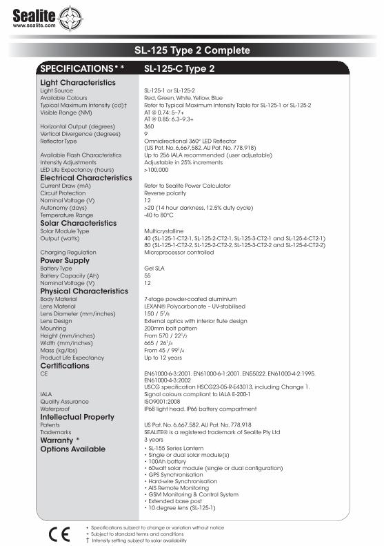
SPECIFICATIONS•* SL-125-C Type 2Light CharacteristicsLight Source SL-125-1 or SL-125-2Available Colours Red, Green, White, Yellow, BlueTypical Maximum Intensity (cd)† Refer to Typical Maximum Intensity Table for SL-125-1 or SL-125-2Visible Range (NM) AT @ 0.74: 5–7+
AT @ 0.85: 6.3–9.3+Horizontal Output (degrees) 360Vertical Divergence (degrees) 9Reflector Type Omnidirectional 360° LED Reflector
(US Pat. No. 6,667,582. AU Pat. No. 778,918)Available Flash Characteristics Up to 256 IALA recommended (user adjustable)Intensity Adjustments Adjustable in 25% incrementsLED Life Expectancy (hours) >100,000
Electrical CharacteristicsCurrent Draw (mA) Refer to Sealite Power CalculatorCircuit Protection Reverse polarityNominal Voltage (V) 12Autonomy (days) >20 (14 hour darkness, 12.5% duty cycle)Temperature Range -40 to 80°C
Solar CharacteristicsSolar Module Type MulticrystallineOutput (watts) 40 (SL-125-1-CT2-1, SL-125-2-CT2-1, SL-125-3-CT2-1 and SL-125-4-CT2-1)
80 (SL-125-1-CT2-2, SL-125-2-CT2-2, SL-125-3-CT2-2 and SL-125-4-CT2-2)Charging Regulation Microprocessor controlled
Power SupplyBattery Type Gel SLABattery Capacity (Ah) 55Nominal Voltage (V) 12
Physical CharacteristicsBody Material 7-stage powder-coated aluminiumLens Material LEXAN® Polycarbonate – UV-stabilisedLens Diameter (mm/inches) 150 / 57/8
Lens Design External optics with interior flute designMounting 200mm bolt patternHeight (mm/inches) From 570 / 221/2
Width (mm/inches) 665 / 261/4
Mass (kg/lbs) From 45 / 991/4
Product Life Expectancy Up to 12 years
CertificationsCE EN61000-6-3:2001. EN61000-6-1:2001. EN55022. EN61000-4-2:1995.
EN61000-4-3:2002USCG specification HSCG23-05-R-E43013, including Change 1.
IALA Signal colours compliant to IALA E-200-1Quality Assurance ISO9001:2008Waterproof IP68 light head. IP66 battery compartment
Intellectual PropertyPatents US Pat. No. 6,667,582. AU Pat. No. 778,918Trademarks SEALITE® is a registered trademark of Sealite Pty Ltd
Warranty * 3 years
Options Available • SL-155 Series Lantern• Single or dual solar module(s)• 100Ah battery • 60watt solar module (single or dual configuration)• GPS Synchronisation • Hard-wire Synchronisation• AIS Remote Monitoring • GSM Monitoring & Control System • Extended base post• 10 degree lens (SL-125-1)

Latest products and information available at www.sealite.com11
SL-125 Series 5-9NM+ LED Marine Lantern
Figure 2.1. SL-125-1/C-1
Figure 2.2. SL-125-1/C-1.T2

Latest products and information available at www.sealite.com12
SL-125 Series 5-9NM+ LED Marine Lantern
Optional ConfigurationsRF Synchronisation (SL-125-CS) TheSL-125maybefittedwithoptionalcommsyncRFmoduleforshortrangeflashsynchronisation-idealformarinaentrancesandaquacultureapplications.
GPS Synchronisation (SL-125-GPS) Forflashsynchronisationoflanternsinstalledoverlongerranges,aGPSmodulemaybefitted.Whenlanternsflashinsynchronisationtheycanbeclearlydistinguishedfromothernavaidsandconfusing background lighting - ideal for rivers and channel marking.
GSM Monitoring & Control (SL-125-GSM) and AIS Integration (SL-125-AIS)TheSL-125lanternseriesmayalsobefittedwithGSMremotemonitoringandcontrolcapabilities-enabling users to access real-time diagnostics data and change lantern settings via cell-phone.AISintegrationenablesremotemonitoringoftheSL-125lanternaswellascrucialMessage21information to be broadcast to mariners within the region.
Radio Control (SL-125-RC)RadiocontrolmaybefittedtoSL-125seriesproductsenablinguserstoremotelymodifythesetupoftheirlanternviahandheldradiocontroller(SL-RC-2.4).Forexample,theoperatorcanremotelychangebetweendifferentcolouredLEDbanks(tochangethecolourofthelight),turntheirlightsONandOFF,orchangetheflashsetting.Perfectforremotetrafficcontrol and to designate an area of activity.

Latest products and information available at www.sealite.com13
SL-125 Series 5-9NM+ LED Marine Lantern
Settings of SL-125 & SL-125-C Models Beforeinstallingthelight,intensityandflashsettingsmustbeset.1. Removethebolt/locksecuringthebatteryboxlid,andopenunit(SL-125-CONLY).2. RemovethebungfromthebaseoftheSL-125light.3. ThepowerandrangesettingsofthelanternareadjustedbysettingtheDIPswitchesinsidethe
lantern.Yourlanternisnormallysettomaximumrange(see‘SelectingIntensity/PowerSetting’section of this manual).
4. Setrotaryswitchestotherequiredflashcode(see‘SelectingaFlashCode’sectionofthismanual).
5. Replacebung.6. A sealed vent on the base allows air transfer without moisture intake, and should not be disturbed.
Note: Lantern is activated by connecting positive and negative battery wires (and solar module wires for SL-125-C).
Activation and Installation of SL-125 1. Battery Connection: Connect “Battery Positive (+)” wire to positive terminal of battery, and “Battery
Negative (-)” wire to negative terminal of battery. Mains Connection: Connect positive and negative wires to 12volt power supply (ONLY). 2. To test place dark cover (towel or jacket) on top of light to activate sensor, light will come on within
one minute.
3. Ensurethattheunitisboltedtoaneven,flatsurface.
Activation and Installation of SL-125-C1. Insidethebatteryboxisaninternalbatterycontainer.Toaccessthebattery,removethefour
screws and lid of this internal container. 2. Connect the “Battery Negative (-)” wire to the negative terminal of the battery, and the “Battery
Positive (+)” wire to the positive terminal of the battery. 3. Connectthe“BatteryPositive(+)”and“BatteryNegative(-)”wiresfromtheSolarRegulatortothe
battery. 4. Replacetheinternalbatterycontainerlidandscrewsmakingsurenowiresareprotruding.5. Close the battery box lid and secure with bolt/lock. Light is now activated. 6. To test place dark cover (towel or jacket) on top of light to activate sensor, light will come on within
one minute.7. Ensurethattheunitisboltedtoaneven,flatsurface.
Care must be taken to observe the polarity of each wire before they are connected.
Note: Refer to ‘Lantern Status’ section of this manual to check the status of the light after activated. Indicated by red and yellow status LED’s viewed at the base of the lens.
Installation
Latest products and information available at www.sealite.com14
SL-125 Series 5-9NM+ LED Marine Lantern
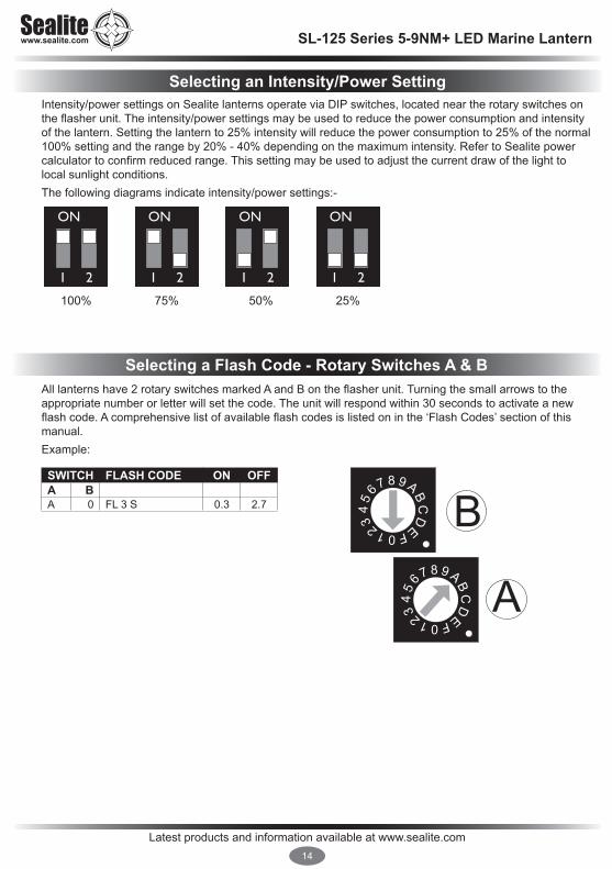
Intensity/powersettingsonSealitelanternsoperateviaDIPswitches,locatedneartherotaryswitchesontheflasherunit.Theintensity/powersettingsmaybeusedtoreducethepowerconsumptionandintensityof the lantern. Setting the lantern to 25% intensity will reduce the power consumption to 25% of the normal 100%settingandtherangeby20%-40%dependingonthemaximumintensity.RefertoSealitepowercalculatortoconfirmreducedrange.Thissettingmaybeusedtoadjustthecurrentdrawofthelighttolocal sunlight conditions. The following diagrams indicate intensity/power settings:-
Alllanternshave2rotaryswitchesmarkedAandBontheflasherunit.Turningthesmallarrowstotheappropriate number or letter will set the code. The unit will respond within 30 seconds to activate a new flashcode.Acomprehensivelistofavailableflashcodesislistedoninthe‘FlashCodes’sectionofthismanual.Example:
100%
1 2
ON
75%
1 2
ON
50%
1 2
ON
25%
1 2
ON
45
6 7 8 9 ABC
D
EF0123
45
6 7 8 9 ABC
D
EF0123 A
BSWITCH FLASH CODE ON OFFA BA 0 FL 3 S 0.3 2.7
Selecting an Intensity/Power Setting
Selecting a Flash Code - Rotary Switches A & B

Latest products and information available at www.sealite.com15
SL-125 Series 5-9NM+ LED Marine Lantern
RF Synchronisation (Comm-Sync) Option Sealite’sinnovativeRFSynchronisationSystemisdesignedtoofferalow-costshortrangeflashsynchronisation option for applications including rivers, estuaries, marina entrances, channel marking andaquaculture.RFSynchronisationmaybefittedtotheSL-125rangeoflanternsandbenefitsvesseloperatorsat night by illuminating the boundary or channel as a clear passage on entrance, as opposed to indiscriminantflashinglightswhichmayrenderthejudgmentofdistancedifficult.
Operating PrincipleRFComm-SyncproductsarefittedwithaninternalRFmodule,whichoperatesona2.4GHzfrequencyandhasanoperationalrangeof1.4kmbetween2lights.Shouldmorethan2lanternsberequiredtobesynchronisedtherangemaybeextendedforlongerdistances as each lantern transmits the data to all adjacent lanterns - causing them to fall into synchronisation. The only limitation is that no lantern should be more than 1.4km from the next lantern in the series.RFComm-Synclanternsoperatewithinapeer-to-peernetworktopologyandthereforearenotdependent upon master/slave relationships. This means that lights remain synchronised without use of master/slaveconfigurationsandeachlanterninthenetworksharesboththerolesofmasterandslave.Usinginnovativesoftware,theadditionalpowerconsumptionisminimal,andinmostconfigurationsthesolarlanternrequiresonly1.5hrsofdirectsunlightperdaytoretainfullworkingautonomy.Synchronisation is recommended for lanterns operating with up to 20% duty cycles and in regions where typical solar irradiation averages 1.5Kwh per day. Flash characters exceeding this may require lantern intensity adjustment. Synchronisation is achieved via short-range RF communication between lanterns, and relies on line-of-sight operation.
SetupToenableflashsynchronisationofindependentRFComm-Synclanterns,setlanternstothesameflashcharacteristic(see“SelectingaFlashCode”sectionofthismanual). IMPORTANT: only lights set to the exact same flash pattern/code will flash in synchronisation.

Latest products and information available at www.sealite.com16
SL-125 Series 5-9NM+ LED Marine Lantern
GPS Synchronisation OptionThis GPS option can be added to any of the SL-125 series lanterns previously outlined, and provides theuserwiththeabilitytoinstallindependentlyoperatinglanternsthatallflashinsynchronisation.Noadditionalpowersupplies,aerialsorcontrolsystemsarerequired,andwithitsmicroprocessor-basedsystem,theGPSoptionisspecificallydesignedtoprovidemaximumreliabilityandperformanceover a wide range of environmental conditions.
Operating PrincipleEachlightoperatesindependentlyandrequiresnooperatorintervention.Aminimumof4satellitesneed to be in view for the built-in GPS receiver to collect time data. At dusk, the light sensor will turn thelighton.Iftimedataisavailablethelightwillcomeonsynchronisedtoeveryotherlightwiththesameselectedflashcode.Synchronisation is achieved using an internal algorithm based on the highly accurate time base and time data received from the satellites. The satellite data is provided from a number of earth stations using atomic clocks as the time base. Continuous self-checking ensures that the light will continue to run in synchronisation.
Light ActivationAt power-up the microprocessor checks that the internal GPS module is programmed correctly and is able to provide valid time base and time data. Once outside with a clear view of the sky, valid data should become available within 20 minutes.
Daylight OperationDuring daylight hours the microprocessor is in idle mode to reduce power consumption. Time data continues to be updated once per second. The microprocessor will automatically exit the idle mode as soon as dark conditions are detected.
Dark OperationWhen dark conditions are detected the light:• Checksforvalidtimedataandisturnedonafteradelaybasedonthecurrenttimeandthelength
oftheselectedflashcode;• Ifvalidtimedataisnotdetectedthelightwillturnonafterapproximately10seconds.Thislightwill
not be synchronised. • Ifthelightturnsonunsynchroniseditwillcontinuallycheckforvalidtimedata.Oncevaliddatais
found the light will automatically synchronise.
Note:Lightswillnotsynchroniseifdifferentflashcodesareselected.

Latest products and information available at www.sealite.com17
SL-125 Series 5-9NM+ LED Marine Lantern
Lantern StatusTwostatusLED’sonthemainprintedcircuitboard(positionAinimagebelow)providetheoperatorwith an indication of the lantern status. ThereisoneredandoneyellowstatusLED.TheredstatusLEDisusedtoindicatethehealthofthelantern’spowersystem.TheyellowstatusLEDisusedtoindicatetheoperationalstatusofthelantern.TheseindicatorLED’scanbeviewedatthebaseofthelens.SeparateindicatorLEDsarelocatedonthetopoftheGPScircuitboard(wherefitted-seepositionB&Coffigure3.1.).
Figure 3.1.

Latest products and information available at www.sealite.com18
SL-125 Series 5-9NM+ LED Marine Lantern
AllSealiteboardsarefittedwithtwoIndicatorLED’s.ThesearepositionedneartheFlashCodeRotarySwitches. Use the table below to help determine operational status.
Yellow LED Lantern Status Lantern Comment
OFF Normal OFF Lantern is in Daylight and in Dusk till Dawn mode or in Standby Mode
Flashing ON 0.15 secondsOFF 0.15 seconds
Normal OFF Light is activating and will turn on after detecting 30 seconds of continuous darkness.
Flashing2 x quick flashes every 2 seconds (Heartbeat)
Normal ON LanternisinNormaloperatingcondition.Itisnotconnected to any GPS synchronisation.
Flashing ON 1.5 secondsOFF 1.5 seconds
Normal ON Normal operating condition. Lantern is synchronised to GPS-enabled lanterns.
Flashing1 x quick flashevery 2 seconds
Normal ON Lanternis‘re-syncing’withGPS.Thelanternre-sync’swiththeGPSevery15minutes.
Flashing2 x quick flashes every 11 seconds
Normal ON LanternisaHardWireSynchronisationSlave.
Red LED Lantern Status Lantern Comment
OFF Normal Normal Battery VoltageFlashing once every 1.6 seconds
Battery Voltage is 12 – 12.5V Battery Voltage is between 12 – 12.5V
Flashing twice every 2 seconds
Battery Voltage is 11.5 – 12V Battery Voltage is between 11.5 – 12V
Flashing 3 x times every 2 seconds
Battery Voltage is 10.5 – 11.5V Battery Voltage is between 10.5 – 11.5V
Flashing 4 x times every 2.5 seconds
Battery Voltage is 10.0 – 10.5V Battery Voltage is between 10.0 – 10.5V
Flashing 5 x times every 3 seconds
Battery Voltage is less than
10.0VBattery Voltage is at less than 10.0V
Fixed-on Flat Battery (<10V) OFF
Flat Battery cut-off is now operational and the lantern will be off. Battery must receive charge (above 12V) and lantern must see daylight for at least 1 minute before resuming normal operation.
Flashing ON 1.5 secondsOFF 1.5 seconds
Battery Voltage is above 13.5V
Battery Voltage is above 13.5V. this may indicate a problem with the solar regulator.

Latest products and information available at www.sealite.com19
SL-125 Series 5-9NM+ LED Marine Lantern
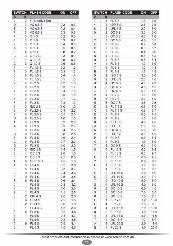
Flash CodesTheSealiteSL-125Seriesmaybesettoanyof256IALArecommendedflashsettingswhichareuser-adjustable onsite without the need for external devices.
SEALITE® code reference is listed by number of flashes
For the latest version of this document visit www.sealite.com or email [email protected]
SymbolsFL FlashfollowedbynumberEg.FL1S,oneflasheverysecondF FixedQ QuickflashVQ VeryquickflashOC Occulting;greaterperiodonthanoffISO Isophase;equalperiodonandoffLFL LongflashlongMO Morse code ( ) contains letter
Forexample,VQ(6)+LFL10Smeans6veryquickflashesfollowedbyalongflash,duringa 10-second interval.The amount of power your lantern draws through the night depends on the duty cycle, i.e. the amount of timeonasaproportiontothetimingcycle.Forexample,0.5secondsonand4.5secondsoffequalsa10% duty cycle. Itisbesttooperateatthelowestdutycycleappropriatetotheactualneedsoftheapplication.
Recommended Rhythm for Flashing Light - IALA Regions A and B
MARK DESCRIPTION RHYTHMPort Hand & Starboard Marks: Any, other than Composite Group Flashing (2+1)
Preferred Channel Starboard: Composite Group Flashing (2+1)
Preferred Channel Port: Composite Group Flashing (2+1)
North Cardinal Mark: Veryquickorquick
East Cardinal Mark: Veryquick(3)every5secondsorquick(3)every10seconds
South Cardinal Mark: Veryquick(6)+longflashevery10secondsorquick(6)+longflashevery15seconds
West Cardinal Mark: Veryquick(9)every10secondsorquick(9)every15seconds
Isolated Danger Mark: Groupflashing(2)
Safe Water Mark: Isophase,occulting,onelongflashevery10secondsorMorseCode“A”
Special Marks: Any,otherthanthosedescribedforCardinal,IsolatedDangerorSafeWaterMarks
Latest products and information available at www.sealite.com.au20
SWITCH FLASH CODE ON OFFA B0 0 F (Steady light)D 3 VQ 0.5 S 0.2 0.3E 3 VQ 0.6 S 0.2 0.4F 3 VQ 0.6 S 0.3 0.37 3 Q 1 S 0.2 0.88 3 Q 1 S 0.3 0.79 3 Q 1 S 0.4 0.6A 3 Q 1 S 0.5 0.58 4 Q 1 S 0.8 0.2B 3 Q 1.2 S 0.3 0.99 4 Q 1.2 S 0.5 0.7C 3 Q 1.2 S 0.6 0.6F 4 FL 1.5 S 0.2 1.31 0 FL 1.5 S 0.3 1.20 5 FL 1.5 S 0.4 1.10 4 FL 1.5 S 0.5 1.02 0 FL 2 S 0.2 1.83 0 FL 2 S 0.3 1.74 0 FL 2 S 0.4 1.65 0 FL 2 S 0.5 1.56 0 FL 2 S 0.7 1.37 0 FL 2 S 0.8 1.21 2 ISO2S 1.0 1.08 0 FL 2.5 S 0.3 2.29 0 FL 2.5 S 0.5 2.0D 6 FL 2.5 S 1.0 1.51 5 FL 3 S 0.2 2.8A 0 FL 3 S 0.3 2.72 5 FL 3 S 0.4 2.6B 0 FL 3 S 0.5 2.53 5 FL 3 S 0.6 2.4C 0 FL 3 S 0.7 2.3D 0 FL 3 S 1.0 2.02 2 ISO3S 1.5 1.55 4 OC 3 S 2.0 1.0E 2 OC 3 S 2.5 0.54 6 OC 3.5 S 2.5 1.04 5 FL 4 S 0.2 3.85 5 FL 4 S 0.3 3.7E 0 FL 4 S 0.4 3.6F 0 FL 4 S 0.5 3.56 5 FL 4 S 0.6 3.40 1 FL 4 S 0.8 3.21 1 FL 4 S 1.0 3.02 1 FL 4 S 1.5 2.53 2 ISO4S 2.0 2.03 6 OC 4 S 2.5 1.5F 2 OC 4 S 3.0 1.03 1 FL 4.3 S 1.3 3.08 5 FL 5 S 0.2 4.84 1 FL 5 S 0.3 4.75 1 FL 5 S 0.5 4.59 5 FL 5 S 0.9 4.16 1 FL 5 S 1.0 4.0
SWITCH FLASH CODE ON OFFA B7 1 FL 5 S 1.5 3.54 2 ISO5S 2.5 2.58 2 LFL 5 S 2.0 3.00 3 OC 5 S 3.0 2.01 3 OC 5 S 4.0 1.02 3 OC 5 S 4.5 0.5C 6 FL 6 S 0.2 5.8B 5 FL 6 S 0.3 5.7C 5 FL 6 S 0.4 5.68 1 FL 6 S 0.5 5.59 1 FL 6 S 0.6 5.4A 1 FL 6 S 1.0 5.07 5 FL 6 S 1.2 4.8B 1 FL 6 S 1.5 4.55 2 ISO6S 3.0 3.09 2 LFL 6 S 2.0 4.06 4 OC 6 S 4.0 2.03 3 OC 6 S 4.5 1.54 3 OC 6 S 5.0 1.0A 4 FL 7 S 1.0 6.09 6 FL 7 S 2.0 5.05 6 OC 7 S 4.5 2.5D 5 FL 7.5 S 0.5 7.0C 1 FL 7.5 S 0.8 6.7E 5 FL 8 S 0.5 7.5B 4 FL 8 S 1.0 7.06 2 ISO8S 4.0 4.0A 2 LFL 8 S 2.0 6.06 6 OC 8 S 5.0 3.0B 2 LFL 8 S 3.0 5.0F 5 FL 9 S 0.9 8.1C 4 FL 9 S 1.0 8.07 6 OC 9 S 6.0 3.00 6 FL 10 S 0.2 9.81 6 FL 10 S 0.3 9.7D 1 FL 10 S 0.5 9.52 6 FL 10 S 0.8 9.2E 1 FL 10 S 1.0 9.01 4 FL 10 S 1.5 8.5C 2 LFL 10 S 2.0 8.0D 2 LFL 10 S 3.0 7.07 2 ISO10S 5.0 5.02 4 LFL 10 S 4.0 6.08 6 OC 10 S 6.0 4.05 3 OC 10 S 7.0 3.06 3 OC 10 S 7.5 2.5F 1 FL 12 S 1.2 10.8D 4 FL 12 S 2.5 9.53 4 LFL 12 S 2.0 10.00 2 FL 15 S 1.0 14.04 4 LFL 15 S 4.0 11.07 4 OC 15 S 10 5.0A 6 LFL 20 S 2.0 18.0E 4 FL 26 S 1.0 25.0

Latest products and information available at www.sealite.com21
SL-125 Series 5-9NM+ LED Marine Lantern
SWITCH FLASH CODE ON OFF ON OFFA B0 A FL (2) 4 S 0.5 1.0 0.5 2.0E B VQ (2) 4 S 0.2 1.0 0.2 2.61 A FL (2) 4.5 S 0.3 1.0 0.3 2.92 A FL (2) 4.5 S 0.4 1.0 0.4 2.73 A FL (2) 4.5 S 0.5 1.0 0.5 2.5F 9 FL (2) 5 S 0.2 0.8 0.2 3.82 C FL (2) 5 S 0.2 1.2 0.2 3.44 A FL (2) 5 S 0.4 0.6 0.4 3.60 7 FL (2) 5 S 0.5 1.0 0.5 3.01 7 FL (2) 5 S 1.0 1.0 1.0 2.09 B Q (2) 5 S 0.3 0.7 0.3 3.72 9 Q (2) 5 S 0.5 0.5 0.5 3.55 A FL (2) 5.5 S 0.4 1.4 0.4 3.37 8 FL (2) 6 S 0.3 0.6 1.0 4.1A A FL (2) 6 S 0.3 0.9 0.3 4.56 A FL (2) 6 S 0.3 1.0 0.3 4.47 A FL (2) 6 S 0.4 1.0 0.4 4.29 9 FL (2) 6 S 0.5 1.0 0.5 4.02 8 FL (2) 6 S 0.8 1.2 0.8 3.23 7 FL (2) 6 S 1.0 1.0 1.0 3.03 9 Q (2) 6 S 0.3 0.7 0.3 4.7A 9 FL (2) 7 S 1.0 1.0 1.0 4.07 B FL (2) 8 S 0.4 0.6 2.0 5.08 A FL (2) 8 S 0.4 1.0 0.4 6.24 7 FL (2) 8 S 0.5 1.0 0.5 6.08 8 FL (2) 8 S 0.8 1.2 2.4 3.65 7 FL (2) 8 S 1.0 1.0 1.0 5.04 C OC (2) 8 S 3.0 2.0 1.0 2.05 C OC (2) 8 S 5.0 1.0 1.0 1.0F B VQ (2) 8 S 0.2 1.0 0.2 6.69 A FL (2) 10 S 0.4 1.6 0.4 7.66 7 FL (2) 10 S 0.5 1.0 0.5 8.07 7 FL (2) 10 S 0.5 1.5 0.5 7.56 9 FL (2) 10 S 0.5 2.0 0.5 7.08 7 FL (2) 10 S 0.8 1.2 0.8 7.2B 9 FL (2) 10 S 1.0 1.0 1.0 7.09 7 FL (2) 10 S 1.0 1.5 1.0 6.54 9 Q (2) 10 S 0.6 0.4 0.6 8.4B A FL (2) 12 S 0.4 1.0 0.4 10.2C 9 FL (2) 12 S 0.5 1.0 0.5 10.0D 9 FL (2) 12 S 1.5 2.0 1.5 7.0A 8 FL (2) 15 S 0.5 1.5 2.0 11.0A 7 FL (2) 15 S 1.0 2.0 1.0 11.08 B Q (2) 15 S 0.2 0.8 0.2 13.8C A FL (2) 20 S 1.0 3.0 1.0 15.0D A FL (2) 25 S 1.0 1.0 1.0 22.0
SWITCH FLASH CODE ON OFF ON OFF ON OFFA B7 9 Q (3) 5 S 0.5 0.5 0.5 0.5 0.5 2.55 9 VQ (3) 5 S 0.2 0.3 0.2 0.3 0.2 3.80 C VQ (3) 5 S 0.3 0.2 0.3 0.2 0.3 3.7E 9 VQ (3) 5 S 0.3 0.3 0.3 0.3 0.3 3.53 C FL (3) 6 S 0.5 1.0 0.5 1.0 0.5 2.52 B FL (2+1) 6 S 0.3 0.4 0.3 1.2 0.3 3.5

Latest products and information available at www.sealite.com22
SL-125 Series 5-9NM+ LED Marine Lantern
SWITCH FLASH CODE ON OFF ON OFF ON OFFA BA B Q (3) 6 S 0.3 0.7 0.3 0.7 0.3 3.7F A FL (3) 8 S 0.5 1.0 0.5 1.0 0.5 4.50 B FL (3) 9 S 0.3 1.0 0.3 1.0 0.3 6.1B 7 FL (3) 9 S 0.8 1.2 0.8 1.2 0.8 4.2B 8 FL (3) 10 S 0.3 0.7 0.3 0.7 0.9 7.1C 8 FL (3) 10 S 0.4 0.6 0.4 0.6 1.2 6.8C B FL (3) 10 S 0.5 0.5 0.5 0.5 0.5 7.5C 7 FL (3) 10 S 0.5 1.5 0.5 1.5 0.5 5.5D B FL (3) 10 S 0.6 0.6 0.6 0.6 0.6 7.0D 7 FL (3) 10 S 1.0 1.0 1.0 1.0 1.0 5.03 8 FL (2+1) 10 S 0.5 0.7 0.5 2.1 0.5 5.78 9 OC (3) 10 S 5.0 1.0 1.0 1.0 1.0 1.0B B Q (3) 10 S 0.3 0.7 0.3 0.7 0.3 7.7D 8 FL (2 + 1) 10 S 0.5 0.5 0.5 0.5 1.5 6.51 B FL (3) 12 S 0.5 1.5 0.5 1.5 0.5 7.5E A FL (3) 12 S 0.5 2.0 0.5 2.0 0.5 6.5E 7 FL (3) 12 S 0.8 1.2 0.8 1.2 0.8 7.2B 6 FL (3) 12 S 1.0 1.0 1.0 3.0 1.0 5.04 8 FL (2+1) 12 S 0.8 1.2 0.8 2.4 0.8 6.05 8 FL (2+1) 12 S 1.0 1.0 1.0 4.0 1.0 4.01 8 FL (2+1) 13.5 S 1.0 1.0 1.0 4.0 1.0 5.5F 7 FL (3) 15 S 0.3 1.7 0.3 1.7 0.3 10.79 D FL (3) 15 S 0.4 1.0 0.4 1.0 0.4 11.80 8 FL (3) 15 S 0.5 1.5 0.5 1.5 0.5 10.5F 8 FL (2+1) 15 S 0.6 0.3 0.6 0.3 1.4 11.80 9 FL (2+1) 15 S 0.7 0.5 0.7 0.5 1.9 10.71 9 FL (2+1) 15 S 0.7 0.7 0.7 0.7 2.1 10.16 8 FL (2+1) 15 S 1.0 2.0 1.0 5.0 1.0 5.01 C VQ (3) 15 S 0.1 0.5 0.1 0.5 0.1 13.74 B FL (3) 20 S 0.5 3.0 0.5 3.0 0.5 12.53 B FL (3) 20 S 0.5 1.5 0.5 1.5 0.5 15.55 B FL (3) 20 S 0.8 1.2 0.8 1.2 0.8 15.26 B FL (3) 20 S 1.0 1.0 1.0 1.0 1.0 15.0
SWITCH FLASH CODE ON OFF ON OFF ON OFF ON OFFA BB F VQ (4) 4 S 0.3 0.3 0.3 0.3 0.3 0.3 0.3 2.3B D Q (4) 6 S 0.3 0.7 0.3 0.7 0.3 0.7 0.3 2.78 D Q (4) 6 S 0.4 0.6 0.4 0.6 0.4 0.6 0.4 2.61 D FL (4) 10 S 0.5 1.0 0.5 1.0 0.5 1.0 0.5 5.02 D FL (4) 10 S 0.8 1.2 0.8 1.2 0.8 1.2 0.8 3.2F E Q (4) 10 S 0.3 0.7 0.3 0.7 0.3 0.7 0.3 6.7B E FL (4) 12 S 0.3 1.7 0.3 1.7 0.3 1.7 0.3 5.74 F FL (4) 12 S 0.5 0.5 0.5 0.5 0.5 0.5 0.5 8.5C E FL (4) 12 S 0.5 1.5 0.5 1.5 0.5 1.5 0.5 5.53 D FL (4) 12 S 0.8 1.2 0.8 1.2 0.8 1.2 0.8 5.2A D Q (4) 12 S 0.3 0.7 0.3 0.7 0.3 0.7 0.3 8.74 D FL (4) 15 S 0.5 1.5 0.5 1.5 0.5 1.5 0.5 8.58 E FL (4) 15 S 1.0 1.0 1.0 1.0 1.0 1.0 1.0 8.07 D FL (4) 15 S 1.5 0.5 0.5 0.5 0.5 0.5 0.5 10.5D E FL (4) 16 S 0.5 1.5 0.5 1.5 0.5 1.5 0.5 9.5C D FL (4) 20 S 0.3 3.0 0.3 3.0 0.3 3.0 0.3 9.85 D FL (4) 20 S 0.5 1.5 0.5 1.5 0.5 1.5 0.5 13.50 D FL (4) 20 S 0.5 1.5 0.5 1.5 0.5 4.5 0.5 10.53 F FL (4) 20 S 1.5 1.5 1.5 1.5 1.5 1.5 1.5 9.50 F Q (4) 20 S 0.5 0.5 0.5 0.5 0.5 0.5 0.5 16.5E E Q (4) 28 S 0.5 0.5 0.5 0.5 0.5 0.5 0.5 24.56 F FL (4) 30 S 0.5 0.5 0.5 0.5 0.5 0.5 0.5 26.5

Latest products and information available at www.sealite.com23
SL-125 Series 5-9NM+ LED Marine Lantern
SWITCH FLASH CODE ON OFF ON OFF ON OFF ON OFF ON OFF ON OFF ON OFF ON OFF ON OFFA B4 E VQ (9) 10 S 0.2 0.3 0.2 0.3 0.2 0.3 0.2 0.3 0.2 0.3 0.2 0.3 0.2 0.3 0.2 0.3 0.2 5.85 E VQ (9) 10 S 0.3 0.3 0.3 0.3 0.3 0.3 0.3 0.3 0.3 0.3 0.3 0.3 0.3 0.3 0.3 0.3 0.3 4.91 F Q (9) 15 S 0.2 0.8 0.2 0.8 0.2 0.8 0.2 0.8 0.2 0.8 0.2 0.8 0.2 0.8 0.2 0.8 0.2 6.80 E Q (9) 15 S 0.3 0.7 0.3 0.7 0.3 0.7 0.3 0.7 0.3 0.7 0.3 0.7 0.3 0.7 0.3 0.7 0.3 6.71 E Q (9) 15 S 0.6 0.6 0.6 0.6 0.6 0.6 0.6 0.6 0.6 0.6 0.6 0.6 0.6 0.6 0.6 0.6 0.6 4.8
SWITCH FLASH CODE ON OFF ON OFF ON OFF ON OFFA BMORSECODE()INDICATESLETTER7 8 MO (A) 6 S 0.3 0.6 1.0 4.17 B MO (A) 8 S 0.4 0.6 2.0 5.08 8 MO (A) 8 S 0.8 1.2 2.4 3.6B 8 MO (U) 10 S 0.3 0.7 0.3 0.7 0.9 7.1C 8 MO (U) 10 S 0.4 0.6 0.4 0.6 1.2 6.8D 8 MO (U) 10 S 0.5 0.5 0.5 0.5 1.5 6.59 8 MO (A) 10 S 0.5 0.5 1.5 7.58 9 MO (D) 10 S 5.0 1.0 1.0 1.0 1.0 1.0A 8 MO (A) 15 S 0.5 1.5 2.0 11.0F 8 MO (U) 15 S 0.6 0.3 0.6 0.3 1.4 11.80 9 MO (U) 15 S 0.7 0.5 0.7 0.5 1.9 10.71 9 MO (U) 15 S 0.7 0.7 0.7 0.7 2.1 10.17 D MO (B) 15 S 1.5 0.5 0.5 0.5 0.5 0.5 0.5 10.5
SWITCH FLASH CODE ON OFF ON OFF ON OFF ON OFF ON OFFA BD D Q (5) 7 S 0.3 0.7 0.3 0.7 0.3 0.7 0.3 0.7 0.3 2.7E D Q (5) 10 S 0.3 0.7 0.3 0.7 0.3 0.7 0.3 0.7 0.3 5.7E 8 FL (5) 12 S 0.5 1.5 0.5 1.5 0.5 1.5 0.5 1.5 0.5 3.55 F FL (5) 20 S 0.5 0.5 0.5 0.5 0.5 0.5 0.5 0.5 0.5 15.59 F FL (5) 20 S 0.8 1.2 0.8 1.2 0.8 1.2 0.8 1.2 0.8 11.29 E FL (5) 20 S 1.0 1.0 1.0 1.0 1.0 1.0 1.0 1.0 1.0 11.0
SWITCH FLASH CODE ON OFF ON OFF ON OFF ON OFF ON OFF ON OFFA BF D Q (6) 10 S 0.3 0.7 0.3 0.7 0.3 0.7 0.3 0.7 0.3 0.7 0.3 4.7A F FL (6) 15 S 0.3 0.7 0.3 0.7 0.3 0.7 0.3 0.7 0.3 0.7 0.3 9.77 F FL (6) 15 S 0.5 1.0 0.5 1.0 0.5 1.0 0.5 1.0 0.5 1.0 0.5 7.0
SWITCH FLASH CODE ON OFF ON OFF ON OFF ON OFF ON OFF ON OFF ON OFFA B6 E VQ (6) + LFL 10 S 0.2 0.3 0.2 0.3 0.2 0.3 0.2 0.3 0.2 0.3 0.2 0.3 2.0 5.07 E VQ (6) + LFL 10 S 0.3 0.3 0.3 0.3 0.3 0.3 0.3 0.3 0.3 0.3 0.3 0.3 2.0 4.42 F Q (6) + LFL 15 S 0.2 0.8 0.2 0.8 0.2 0.8 0.2 0.8 0.2 0.8 0.2 0.8 2.0 7.02 E Q (6) + LFL 15 S 0.3 0.7 0.3 0.7 0.3 0.7 0.3 0.7 0.3 0.7 0.3 0.7 2.0 7.03 E Q (6) + LFL 15 S 0.6 0.6 0.6 0.6 0.6 0.6 0.6 0.6 0.6 0.6 0.6 0.6 2.0 5.88 F VQ (6) + LFL 15 S 0.3 0.3 0.3 0.3 0.3 0.3 0.3 0.3 0.3 0.3 0.3 0.3 2.0 9.4

Latest products and information available at www.sealite.com24
SL-125 Series 5-9NM+ LED Marine Lantern
Maintenance and ServicingDesignedtobevirtuallymaintenance-free,theSL-125,SL-125-C,&SL-125-GPSrequireminimalattention, though the following maintenance and servicing information is provided to help ensure the life of your Sealite product. 1. CleaningLens-occasionalcleaningofthelightlensmayberequired.Usingaclothandwarm
soapy water, wipe off any foreign matter before rinsing the lens with fresh water.2. CleaningSolarPanels-occasionalcleaningofthesolarpanelsmayberequired.Usingacloth
and warm soapy water, wipe off any foreign matter before rinsing the panels with fresh water (SL-125-C models only).
3. Battery Check- inspection of batteries should be performed every three years (minimum) to ensure that the charger, battery and ancillary electronics are functioning correctly. Using a voltage meter, check that the battery voltage is at least 12 volts under 100mA load, and ensure all terminals are clear of foreign matter (SL-125-C models only).
Replacing the BatteryThe SL-125-C lanterns have a sealed battery compartment, which provides the user with the ability to change the battery after years of operation. 1. Removethebolt/locksecuringthebatteryboxlid,andopenunit.2. Insidethebatteryboxisaninternalbatterycontainer.Toaccessthebattery,removethefour
screws and lid of this internal container. 3. Removeoldbatteryfromcontaineranddisconnectallconnectingwires.Discardbatteryinasafe
manner. 4. Connect the “Battery Negative (-)” wire to the negative terminal of the new battery, and the “Battery
Positive (+)” wire to the positive terminal of the new battery. 5. Connectthe“BatteryPositive(+)”and“BatteryNegative(-)”wiresfromtheSolarRegulatortothe
battery.6. Replacetheinternalbatterycontainerlidandscrewsmakingsurenowiresareprotruding.7. Close the battery box lid and secure with bolt/lock. Light is now activated. 8. To test place dark cover (towel or jacket) on top of light to activate sensor, light will come on within
one minute.
Care must be taken to observe the polarity of each wire before they are connected. To ensure waterproofing of the unit, make sure that no wires are protruding and that there is an
even seal. Always discard old batteries in a safe manner.

Latest products and information available at www.sealite.com25
SL-125 Series 5-9NM+ LED Marine Lantern
Trouble ShootingProblem RemedyLantern will not activate. • Ensurelanternisindarkness.
• Waitatleast60secondsfortheprogramtoinitialiseindarkness.• Ensureswitchsettingisonavalidcode(notunusedflashcode).• Ensurebatteryterminalsareproperlyconnected.• Ensurebatteryvoltageisabove12volts.
Timing codes will not change. • Turnrotaryswitchesseveraltimestoensurecontactsareclear.
Lantern will not operate for the entire night.
• Exposelanterntodirectsunlightandmonitoroperationforseveraldays.Sealiteproductstypicallyrequire1.5hoursofdirectsunlightperdaytoretainfullautonomy.Fromadischargedstate,thelanternmayrequireseveraldaysofoperationalconditionsto‘cycle’uptofullautonomy.
• Reducingthelightoutputintensityordutycycle(flashcode)willreducecurrent draw on the battery.
• Ensuresolarmoduleiscleanandnotcoveredbyshadingduringtheday.

Latest products and information available at www.sealite.com26
SL-125 Series 5-9NM+ LED Marine Lantern
Activating the WarrantyUpon purchase, the Sealite Pty Ltd warranty must be activated for recognition of future claims. To do this you needtoregisteron-line.PleasecompletetheOnlineRegistrationFormat:www.sealite.comSealite Pty Ltd will repair or replace your LED light in the event of electronic failure for a period of up to three years from the date of purchase, as per the terms & conditions below.Sealite Pty Ltd will repair or replace any ancillary or accessory products in the event of failure for a period of up to one year from the date of purchase, as per the terms & conditions below.The unit(s) must be returned to Sealite freight prepaid.Warranty Terms 1. SealitePtyLtdwarrantsthatanySealitemarineproductsfittedwithtelemetryequipmentincludingbut
notlimitedtoAIS,GSM,GPSorRF(“TelemetryProducts”)willbefreefromdefectivematerialsandworkmanship under normal and intended use, subject to the conditions hereinafter set forth, for a period of twelve (12) months from the date of purchase by the original purchaser.
2. SealitePtyLtdwarrantsthatanyBargeSafe™SeriesofLEDbargelightproducts(“BargeSafe™Products”) will be free from defective materials and workmanship under normal and intended use, subject to the conditions hereinafter set forth, for a period of twelve (12) months from the date of purchase by the original purchaser.
3. SealitePtyLtdwarrantsthatanyLEDarealightingproducts(“AreaLightingProducts”)butnotincludingsign lighting products will be free from defective materials and workmanship under normal and intended use, subject to the conditions hereinafter set forth, for a period of twelve (12) months from the date of purchase by the original purchaser.
4. Sealite Pty Ltd warrants that any ancillary products and accessories, not mentioned in other clauses in this section, will be free from defective materials and workmanship under normal and intended use, subject to the conditions hereinafter set forth, for a period of twelve (12) months from the date of purchase by the original purchaser.
5. SealitePtyLtdwarrantsthatanyLEDsignlightingproducts(“SignLightingProducts”)willbefreefromdefective materials and workmanship under normal and intended use, subject to the conditions hereinafter set forth, for a period of three (3) years from the date of purchase by the original purchaser.
6. Sealite Pty Ltd warrants that any Sealite marine lighting products other than the Telemetry Products, BargeSafe™ Products, and Area Lighting Products (“Sealite Products”) will be free from defective materials and workmanship under normal and intended use, subject to the conditions hereinafter set forth, for a period of three (3) years from the date of purchase by the original purchaser.
7. SealitePtyLtdwillrepairorreplace,atSealite’ssolediscretion,anyTelemetryProducts,BargeSafe™Products, Area Lighting Products or Sealite Products found to be defective in material and workmanship in therelevantwarrantyperiodsolongastheWarrantyConditions(setoutbelow)aresatisfied.
8. IfanyTelemetryProducts,BargeSafe™Products,AreaLightingProductsorSealiteProductsarefittedwith a rechargeable battery, Sealite Pty Ltd warrants the battery will be free from defect for a period of one (1)yearwhenusedwithinoriginalmanufacturer’sspecificationsandinstructions.
9. Buoyproductsarecoveredbyaseparate‘SealiteBuoyWarranty’.
Warranty ConditionsThisWarrantyissubjecttothefollowingconditionsandlimitations;1. The warranty is applicable to lanterns manufactured from 1/1/2009.2. The warranty is void and inapplicable if:
a. theproducthasbeenusedorhandledotherthaninaccordancewiththeinstructionsintheowner’smanualandanyotherinformationorinstructionsprovidedtothecustomerbySealite;
b. the product has been deliberately abused, or misused, damaged by accident or neglect or in being transported;or
c. the defect is due to the product being repaired or tampered with by anyone other than Sealite or
Sealite LED Light Warranty V2.2
Latest products and information available at www.sealite.com27
SL-125 Series 5-9NM+ LED Marine Lantern
Informationinthismanualissubjecttochangewithoutnoticeanddoesnotrepresentacommitmentonthepartofthevendor. Sealite products are subject to certain Australian and worldwide patent applications.
authorised Sealite repair personnel. 3. The customer must give Sealite Pty Ltd notice of any defect with the product within 30 days of the
customer becoming aware of the defect. 4. Rechargeablebatterieshavealimitednumberofchargecyclesandmayeventuallyneedtobereplaced.
Typical battery replacement period is 3-4 years. Long term exposure to high temperatures will shorten the batterylife.Batteriesusedorstoredinamannerinconsistentwiththemanufacturer’sspecificationsandinstructions shall not be covered by this warranty.
5. NomodificationstotheoriginalspecificationsdeterminedbySealiteshallbemadewithoutwrittenapproval of Sealite Pty Ltd.
6. Sealitelightscanbefittedwith3rdpartypowersuppliesandaccessoriesbutarecoveredbythe3rdpartywarranty terms and conditions.
7. The product must be packed and returned to Sealite Pty Ltd by the customer at his or her sole expense. Sealite Pty Ltd will pay return freight of its choice. A returned product must be accompanied by a written description of the defect and a photocopy of the original purchase receipt. This receipt must clearly list model and serial number, the date of purchase, the name and address of the purchaser and authorised dealer and the price paid by the purchaser. On receipt of the product, Sealite Pty Ltd will assess the product and advise the customer as to whether the claimed defect is covered by this warranty.
8. Sealite Pty Ltd reserves the right to modify the design of any product without obligation to purchasers of previouslymanufacturedproductsandtochangethepricesorspecificationsofanyproductwithoutnoticeor obligation to any person.
9. Inputvoltageshallnotexceedthoserecommendedfortheproduct.10. Warranty does not cover damage caused by the incorrect replacement of battery in solar lantern models.11. Thiswarrantydoesnotcoveranydamageordefectcausedtoanyproductasaresultofwaterfloodingor
any other acts of nature.12. There are no representations or warranties of any kind by Sealite or any other person who is an agent,
employee,orotherrepresentativeoraffiliateofSealite,expressorimplied,withrespecttoconditionofperformanceofanyproduct,theirmerchantability,orfitnessforaparticularpurpose,orwithrespecttoanyother matter relating to any products.
Limitation of LiabilityTo the extent permitted by acts and regulations applicable in the country of manufacture, the liability of Sealite Pty Ltd under this Warranty will be, at the option of Sealite Pty Ltd, limited to either the replacement or repair of anydefectiveproductcoveredbythisWarranty.SealitewillnotbeliabletoBuyerforconsequentialdamagesresultingfromanydefectordeficiencies.
Limited to Original Purchaser ThisWarrantyisforthesolebenefitoftheoriginalpurchaserofthecoveredproductandshallnotextendtoanysubsequentpurchaseroftheproduct.
MiscellaneousApartfromthespecificwarrantiesprovidedunderthiswarranty,allotherexpressorimpliedwarrantiesrelatingto the above product is hereby excluded to the fullest extent allowable under law. The warranty does not extendtoanylostprofits,lossofgoodwilloranyindirect,incidentalorconsequentialcostsordamagesorlosses incurred by the purchaser as a result of any defect with the covered product.
WarrantorSealitePtyLtdhasauthoriseddistributioninmanycountriesoftheworld.Ineachcountry,theauthorisedimporting distributor has accepted the responsibility for warranty of products sold by distributor. Warranty serviceshouldnormallybeobtainedfromtheimportingdistributorfromwhomyoupurchasedyourproduct.Intheeventofservicerequiredbeyondthecapabilityoftheimporter,SealitePtyLtdwillfulfiltheconditionsofthewarranty.Suchproductmustbereturnedattheowner’sexpensetotheSealitePtyLtdfactory,togetherwith a photocopy of the bill of sale for that product, a detailed description of the problem, and any information necessary for return shipment.

Latest products and information available at www.sealite.com28
SL-125 Series 5-9NM+ LED Marine Lantern
Marine Lanterns (1–19NM)
Bridge & Barge Lights
Area Lighting
Monitoring & Control Systems
Marine Buoys(up to 3mt in diameter)
Mooring Systems & Accessories
Other Sealite Products Available
Head OfficeSealite Pty Ltd11IndustrialDriveSomerville, Vic 3912 AustraliaTel: +61 3 5977 6128 Fax: +61 3 5977 6124Email:[email protected]:www.sealite.com


