50
SL1 and SLV pumps 1.1 - 11 kW, 50 Hz Installation and operating instructions GRUNDFOS INSTRUCTIONS

SL1 and SLV pumps1.1 - 11 kW, 50 Hz
Installation and operating instructions
GRUNDFOS INSTRUCTIONS

En
glis
h (G
B)
English (GB) Installation and operating instructions
Original installation and operating instructions.
CONTENTSPage
1. Symbols used in this document
2. General descriptionThis booklet includes instructions for installation, operation and maintenance of Grundfos SL1 and SLV submersible sewage and wastewater pumps with motors of 1.1 to 11 kW. Grundfos SL1 and SLV sewage and wastewater pumps are designed for pumping domestic, municipal and industrial sewage and wastewater.
Two types of pumps are available:
• SL1 sewage pumps with S-tube impeller
• SLV sewage pumps with SuperVortex, free-flow impeller.
The pumps can be installed on an auto-coupling system or stand freely on the bottom of a tank.
Grundfos SL1 and SLV pumps are designed with an S-tube and SuperVortex impeller, respectively, to ensure reliable and optimum operation.
The booklet also includes specific instructions for the explosion-proof pumps.
1. Symbols used in this document 2
2. General description 22.1 Product drawing 32.2 Control and monitoring 32.3 Applications 32.4 Operating conditions 3
3. Delivery and handling 43.1 Transportation 43.2 Storage 4
4. Identification 44.1 Nameplate 44.2 Type key 5
5. Approvals 65.1 Approval standards 65.2 Explanation to Ex approval 6
6. Safety 76.1 Potentially explosive environments 7
7. Installation 87.1 Submerged installation on auto-coupling 87.2 Free-standing submerged installation on ring stand 97.3 Torques for suction and discharge flanges 9
8. Electrical connection 108.1 Wiring diagrams 118.2 Pump controllers 138.3 Thermal switch, Pt1000 and PTC thermistor 138.4 WIO sensor (water-in-oil sensor) 138.5 Moisture switch 138.6 IO 113 148.7 Frequency converter operation 14
9. Startup 159.1 General startup procedure 159.2 Operating modes 159.3 Direction of rotation 16
10. Maintenance and service 1610.1 Inspection 1610.2 Dismantling the pump 1710.3 Assembling the pump 1810.4 Oil quantities 1910.5 Service kits 1910.6 Contaminated pumps 19
11. Fault finding 20
12. Technical data 21
13. Disposal 22
Warning
Prior to installation, read these installation and operating instructions. Installation and operation must comply with local regulations and accepted codes of good practice.
Warning
The use of this product requires experience with and knowledge of the product.Persons with reduced physical, sensory or mental capabilities must not use this product, unless they are under supervision or have been instructed in the use of the product by a person responsible for their safety.Children must not use or play with this product.
Warning
If these safety instructions are not observed, it may result in personal injury.
Warning
If these instructions are not observed, it may lead to electric shock with consequent risk of serious personal injury or death.
Warning
These instructions must be observed for explosion-proof pumps. We recommend that you also follow these instructions for standard pumps.
CautionIf these safety instructions are not observed, it may result in malfunction or damage to the equipment.
NoteNotes or instructions that make the job easier and ensure safe operation.
2
En
gli
sh
(G
B)
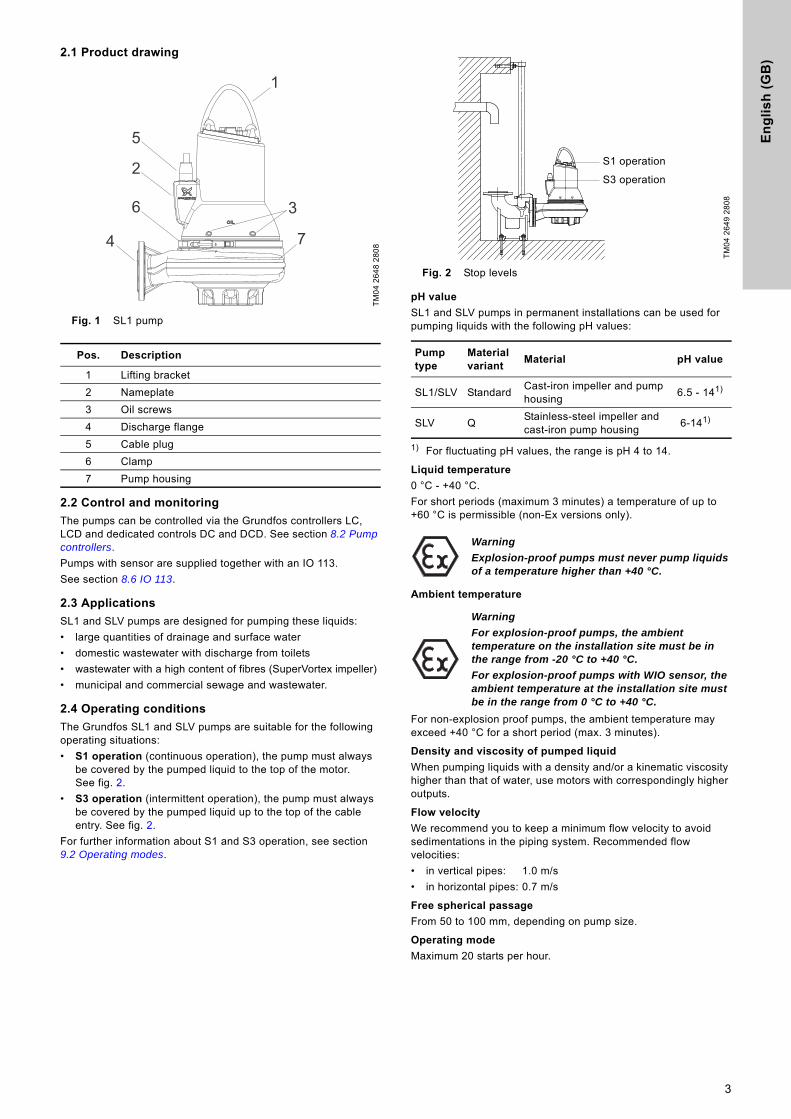
2.1 Product drawing
Fig. 1 SL1 pump
2.2 Control and monitoring
The pumps can be controlled via the Grundfos controllers LC, LCD and dedicated controls DC and DCD. See section 8.2 Pump controllers.
Pumps with sensor are supplied together with an IO 113.
See section 8.6 IO 113.
2.3 Applications
SL1 and SLV pumps are designed for pumping these liquids:
• large quantities of drainage and surface water
• domestic wastewater with discharge from toilets
• wastewater with a high content of fibres (SuperVortex impeller)
• municipal and commercial sewage and wastewater.
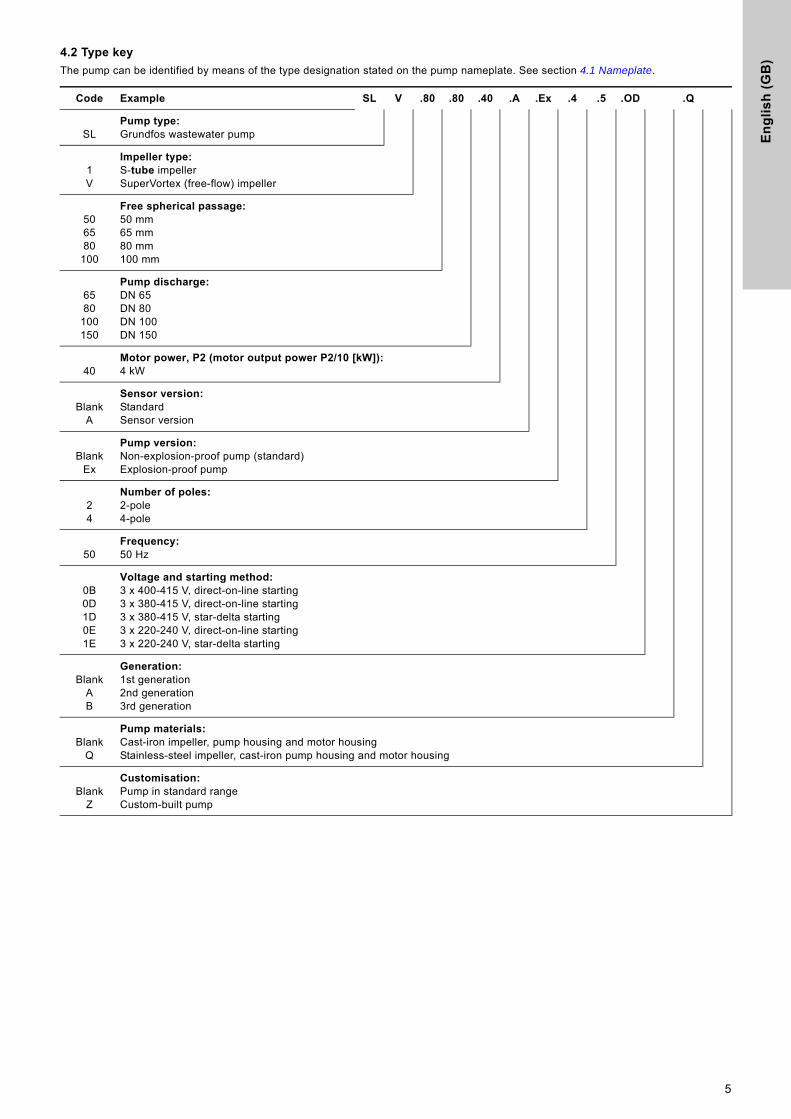
2.4 Operating conditions
The Grundfos SL1 and SLV pumps are suitable for the following operating situations:
• S1 operation (continuous operation), the pump must always be covered by the pumped liquid to the top of the motor. See fig. 2.
• S3 operation (intermittent operation), the pump must always be covered by the pumped liquid up to the top of the cable entry. See fig. 2.
For further information about S1 and S3 operation, see section 9.2 Operating modes.
Fig. 2 Stop levels
pH value
SL1 and SLV pumps in permanent installations can be used for pumping liquids with the following pH values:
1) For fluctuating pH values, the range is pH 4 to 14.
Liquid temperature
0 °C - +40 °C.
For short periods (maximum 3 minutes) a temperature of up to +60 °C is permissible (non-Ex versions only).
Ambient temperature
For non-explosion proof pumps, the ambient temperature may exceed +40 °C for a short period (max. 3 minutes).
Density and viscosity of pumped liquid
When pumping liquids with a density and/or a kinematic viscosity higher than that of water, use motors with correspondingly higher outputs.
Flow velocity
We recommend you to keep a minimum flow velocity to avoid sedimentations in the piping system. Recommended flow velocities:
• in vertical pipes: 1.0 m/s
• in horizontal pipes: 0.7 m/s
Free spherical passage
From 50 to 100 mm, depending on pump size.
Operating mode
Maximum 20 starts per hour.
TM
04
26
48
28
08
Pos. Description
1 Lifting bracket
2 Nameplate
3 Oil screws
4 Discharge flange
5 Cable plug
6 Clamp
7 Pump housing
1
5
2
6
4
3
7
TM
04
26
49
28
08
Pump type
Material variant
Material pH value
SL1/SLV StandardCast-iron impeller and pump housing
6.5 - 141)
SLV QStainless-steel impeller and cast-iron pump housing
6-141)
Warning
Explosion-proof pumps must never pump liquids of a temperature higher than +40 °C.
Warning
For explosion-proof pumps, the ambient temperature on the installation site must be in the range from -20 °C to +40 °C.
For explosion-proof pumps with WIO sensor, the ambient temperature at the installation site must be in the range from 0 °C to +40 °C.
S1 operation
S3 operation
3

En
glis
h (G
B)
3. Delivery and handlingThe pump may be transported and stored in a vertical or horizontal position. Make sure that it cannot roll or fall over.
3.1 Transportation
All lifting equipment must be rated for the purpose and checked for damage before any attempts to lift the pump. The lifting equipment rating must under no circumstances be exceeded. The pump weight is stated on the pump nameplate.
3.2 Storage
During long periods of storage, the pump must be protected against moisture and heat.
Storage temperature: -30 °C - +60 °C
If the pump has been in use, the oil should be changed before storage.
After a long period of storage, the pump should be inspected before it is put into operation. Make sure that the impeller can rotate freely. Pay special attention to the condition of the shaft seal, O-rings, oil and the cable entry.
4. Identification
4.1 Nameplate
The nameplate states the operating data and approvals applying to the pump. The nameplate is fitted to the side of the motor housing close to the cable entry.
Fix the extra nameplate supplied with the pump to the cable end in the control cabinet.
Fig. 3 Nameplate
Warning
Always lift the pump by its lifting bracket or by means of a fork-lift truck if the pump is fixed on a pallet. Never lift the pump by means of the motor cable or the hose/pipe.
Warning
If the pump is stored for more than one year or it takes a long time before it is put into operation after the installation, the impeller must be turned at least once a month. T
M0
4 3
29
7 4
10
8
Pos. Description
1 Ex mark
2 Type designation
3 Model number
4 Production code (year/week)
5 Maximum head
6 Maximum installation depth
7 Number of phases
8 Rated voltage, D
9 Rated voltage, Y
10 Rated input power
11 Power factor
13 Country of production
14 CE mark
16 Maximum liquid temperature
17 Maximum flow rate
19 Enclosure class to IEC
20 Rated speed
21 Frequency
22 Rated current, D
23 Rated current, Y
24 Shaft power
25 Insulation class
27 Weight without cable
Type:Model: P.c. IP68 mHmax:Motor:P1:
Qmax:Tmax.:
n:
kg
minkW
VA
m m h/3
CkWP2:
-1 Cos :
VA
Hz Insul.class: Weight:
Made in Tatabanya. Hungary
9808
5993
3
5 1716
619
7
820
9
10 2411
252721
4
1
2
14
2223
13
H
4
En
gli
sh
(G
B)
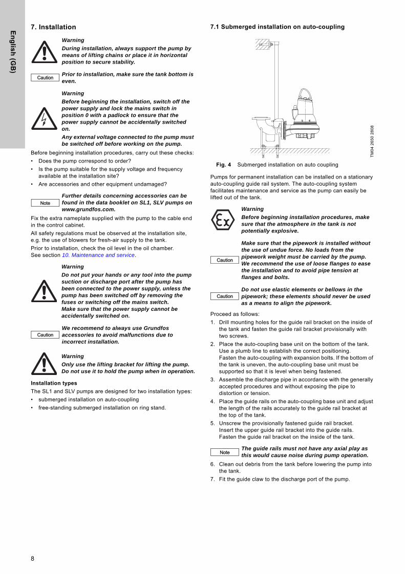
4.2 Type key
The pump can be identified by means of the type designation stated on the pump nameplate. See section 4.1 Nameplate.
Code Example SL V .80 .80 .40 .A .Ex .4 .5 .OD .Q
SLPump type:Grundfos wastewater pump
1V
Impeller type:S-tube impellerSuperVortex (free-flow) impeller
506580
100
Free spherical passage:50 mm65 mm80 mm100 mm
6580
100150
Pump discharge:DN 65DN 80DN 100DN 150
40Motor power, P2 (motor output power P2/10 [kW]):4 kW
BlankA
Sensor version:StandardSensor version
BlankEx
Pump version:Non-explosion-proof pump (standard)Explosion-proof pump
24
Number of poles:2-pole4-pole
50Frequency:50 Hz
0B0D1D0E1E
Voltage and starting method:3 x 400-415 V, direct-on-line starting3 x 380-415 V, direct-on-line starting3 x 380-415 V, star-delta starting3 x 220-240 V, direct-on-line starting3 x 220-240 V, star-delta starting
BlankAB
Generation:1st generation2nd generation3rd generation
BlankQ
Pump materials:Cast-iron impeller, pump housing and motor housingStainless-steel impeller, cast-iron pump housing and motor housing
BlankZ
Customisation:Pump in standard rangeCustom-built pump
5

En
glis
h (G
B)
5. ApprovalsThe SL1 and SLV pumps have been tested by KEMA. The explosion-proof versions hold two examination certificates:
• ATEX (EU): KEMA08ATEX0125X
• IECEX: IECEX KEM08.0039X
Both certificates have been issued by KEMA according to the ATEX directive.
5.1 Approval standards
The standard variants are approved by LGA (notified body under the Construction Products Directive) according to EN 12050-1 or EN 12050-2 as specified on the pump nameplate.
5.2 Explanation to Ex approval
The SL1 and SLV pumps have the following explosion protection classifications:
5.2.1 Europe
5.2.2 Australia
Explosion proof variants for Australia are approved as Ex d IIB T3/T4 Gb or Ex d mb T3/T4 Gb.
Direct-drive pump, without sensor: CE 0344 II 2 G Ex c d IIB T4 Gb
Direct-drive pump, with sensor: CE 0344 II 2 G Ex c d mb IIB T4 Gb
Pump driven by frequency converter, without sensor: CE 0344 II 2 G Ex c d IIB T3 Gb
Pump driven by frequency converter, with sensor: CE 0344 II 2 G Ex c d mb IIB T3 Gb
Directive/standard Code Description
ATEX
CE 0344 =CE marking of conformity according to the ATEX directive 94/9/EC, Annex X. 0344 is the number of the notified body which has certified the quality system for ATEX.
= Marking of explosion protection.
II =Equipment group according to the ATEX directive, Annex II, point 2.2, defining the requirements applicable to the equipment in this group.
2 =Equipment category according to the ATEX directive, Annex II, point 2.2, defining the requirements applicable to the equipment in this category.
G = Explosive atmosphere caused by gases or vapours.
Harmonized European standard EN 60079-0
Ex = The equipment conforms to harmonized European standard.
c Constructional safety according to EN 13463-5:2011 and EN 13463-1:2009.
d = Flameproof enclosure according to EN 60079-1:2007.
mb = Encapsulation according to EN 60079-18:2009.
II = Suitable for use in explosive atmospheres (not mines).
B = Classification of gases, see EN 60079-0:2012, Annex A. Gas group B includes gas group A.
T4/T3 = Maximum surface temperature is 135 °C / 200 °C according to EN 60079-0:2012.
Gb = Equipment protection level.
X =The letter X in the certificate number indicates that the equipment is subject to special conditions for safe use. The conditions are mentioned in the certificate and the installation and operating instructions.
Standard Code Description
IEC 60079-0 and IEC 60079-1
Ex = Area classification according to AS 2430.1.
d = Flameproof enclosure according to IEC 60079-1:2007.
mb = Encapsulation according to IEC 60079-18:2009.
II = Suitable for use in explosive atmospheres (not mines).
B = Classification of gases, see IEC 60079-0:2011, Annex A. Gas group B includes gas group A.
T4/T3 = Maximum surface temperature is 135 °C / 200 °C according to IEC 60079-0:2011.
Gb = Equipment protection level.
X =The letter X in the certificate number indicates that the equipment is subject to special conditions for safe use. The conditions are mentioned in the certificate and the installation and operating instructions.
6

En
gli
sh
(G
B)
6. SafetyFor safety reasons, all work in tanks must be supervised by a person outside the pump tank.
Tanks for submersible sewage and wastewater pumps may contain sewage or wastewater with toxic and/or disease-causing substances. Therefore, all persons involved must wear appropriate personal protective equipment and clothing, and all work on and near the pump must be carried out under strict observance of the hygiene regulations in force.
6.1 Potentially explosive environments
Use explosion-proof pumps for applications in potentially explosive environments. See section 5.2 Explanation to Ex approval.
Warning
Pump installation in tanks must be carried out by specially trained persons.
Work in or near tanks must be carried out according to local regulations.
Warning
Persons must not enter the installation area when the atmosphere is explosive.
Warning
It must be possible to lock the mains switch in position 0. Type and requirements as specified in EN 60204-1, 5.3.2.
NoteWe recommend you to make all maintenance and service jobs when the pump is placed outside the tank.
Warning
Make sure that the lifting bracket is tightened before attempting to lift the pump. Tighten if necessary. Carelessness during lifting or transportation may cause injury to personnel or damage to the pump.
Warning
SL1 and SLV pumps must under no circumstances be used to pump explosive, flammable or combustible liquids.
Warning
The classification of the installation site must be approved by the local fire-fighting authorities in each individual case.
Special conditions for safe use of SL1 and SLV explosion-proof pumps:
1. Make sure the moisture switch and thermal switches are connected in the same circuit but have separate alarm outputs (motor stop) in case of high humidity or high temperature in the motor.
2. Bolts used for replacement must be class A2-70 or better according to EN/ISO 3506-1.
3. Contact the manufacturer for information on the dimensions of the flameproof joints.
4. The level of pumped liquid must be controlled by two level switches connected to the motor control circuit. The minimum level depends on the installation type and is specified in these installation and operating instructions.
5. Make sure the permanently attached cable is suitably mechanically protected and terminated in a suitable terminal board placed outside the potentially explosive area.
6. The sewage pumps have an ambient temperature range of -20 °C to +40 °C and a maximum process temperature of +40 °C. The minimum ambient temperature for a pump with a water-in-oil sensor is 0 °C.
7. The thermal protection in the stator windings has a nominal switch temperature of 150 °C and must guarantee the disconnection of the power supply; the power supply must be reset manually.
8. The control unit must protect the WIO sensor against short circuit current of the supply to which it is connected. The maximum current from the control unit must be limited to 350 mA.
7
En
glis
h (G
B)
7. Installation
Before beginning installation procedures, carry out these checks:
• Does the pump correspond to order?
• Is the pump suitable for the supply voltage and frequency available at the installation site?
• Are accessories and other equipment undamaged?
Fix the extra nameplate supplied with the pump to the cable end in the control cabinet.
All safety regulations must be observed at the installation site, e.g. the use of blowers for fresh-air supply to the tank.
Prior to installation, check the oil level in the oil chamber. See section 10. Maintenance and service.
Installation types
The SL1 and SLV pumps are designed for two installation types:
• submerged installation on auto-coupling
• free-standing submerged installation on ring stand.
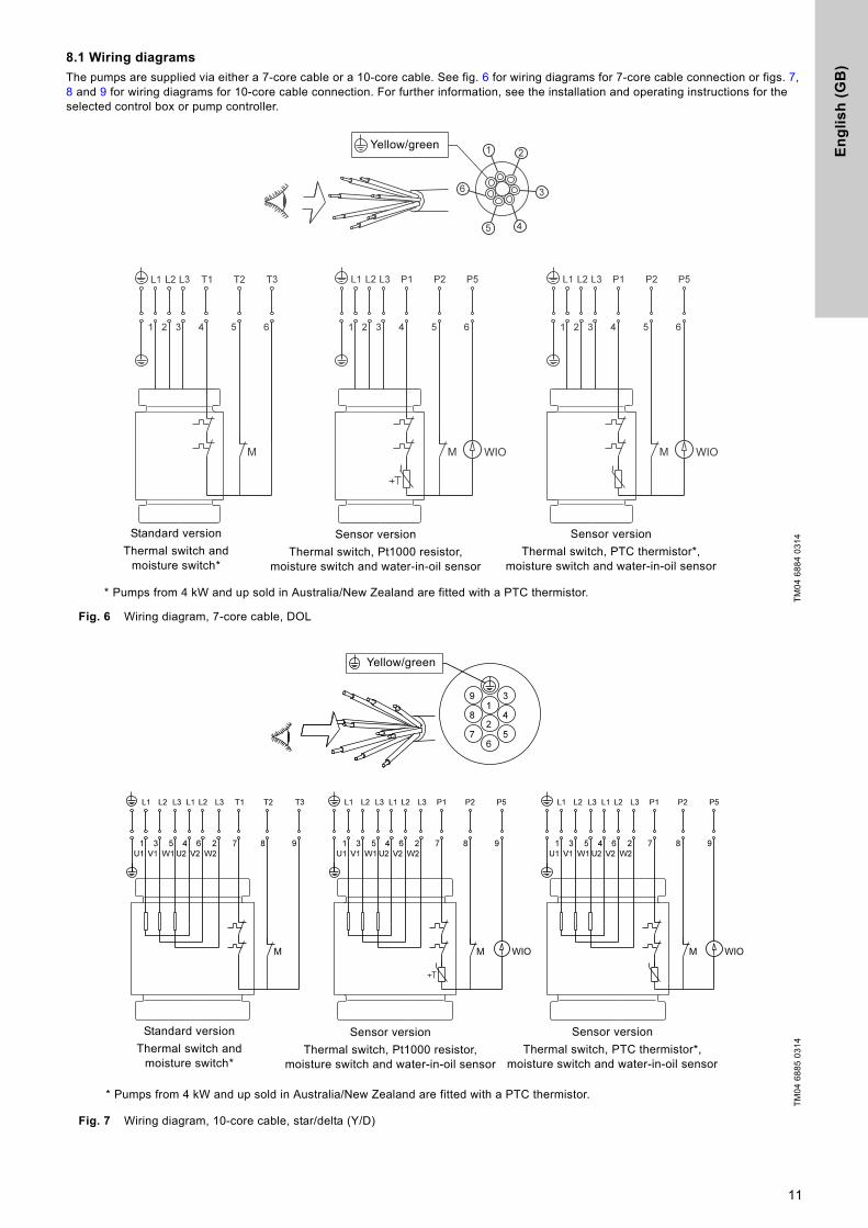
7.1 Submerged installation on auto-coupling
Fig. 4 Submerged installation on auto coupling
Pumps for permanent installation can be installed on a stationary auto-coupling guide rail system. The auto-coupling system facilitates maintenance and service as the pump can easily be lifted out of the tank.
Proceed as follows:
1. Drill mounting holes for the guide rail bracket on the inside of the tank and fasten the guide rail bracket provisionally with two screws.
2. Place the auto-coupling base unit on the bottom of the tank. Use a plumb line to establish the correct positioning. Fasten the auto-coupling with expansion bolts. If the bottom of the tank is uneven, the auto-coupling base unit must be supported so that it is level when being fastened.
3. Assemble the discharge pipe in accordance with the generally accepted procedures and without exposing the pipe to distortion or tension.
4. Place the guide rails on the auto-coupling base unit and adjust the length of the rails accurately to the guide rail bracket at the top of the tank.
5. Unscrew the provisionally fastened guide rail bracket. Insert the upper guide rail bracket into the guide rails. Fasten the guide rail bracket on the inside of the tank.
6. Clean out debris from the tank before lowering the pump into the tank.
7. Fit the guide claw to the discharge port of the pump.
Warning
During installation, always support the pump by means of lifting chains or place it in horizontal position to secure stability.
Caution Prior to installation, make sure the tank bottom is even.
Warning
Before beginning the installation, switch off the power supply and lock the mains switch in position 0 with a padlock to ensure that the power supply cannot be accidentally switched on.
Any external voltage connected to the pump must be switched off before working on the pump.
NoteFurther details concerning accessories can be found in the data booklet on SL1, SLV pumps on www.grundfos.com.
Warning
Do not put your hands or any tool into the pump suction or discharge port after the pump has been connected to the power supply, unless the pump has been switched off by removing the fuses or switching off the mains switch. Make sure that the power supply cannot be accidentally switched on.
CautionWe recommend to always use Grundfos accessories to avoid malfunctions due to incorrect installation.
Warning
Only use the lifting bracket for lifting the pump. Do not use it to hold the pump when in operation.
TM
04
26
50
28
08
Warning
Before beginning installation procedures, make sure that the atmosphere in the tank is not potentially explosive.
Caution
Make sure that the pipework is installed without the use of undue force. No loads from the pipework weight must be carried by the pump. We recommend the use of loose flanges to ease the installation and to avoid pipe tension at flanges and bolts.
CautionDo not use elastic elements or bellows in the pipework; these elements should never be used as a means to align the pipework.
NoteThe guide rails must not have any axial play as this would cause noise during pump operation.
8

En
gli
sh
(G
B)
8. Slide the guide claw of the pump between the guide rails and lower the pump into the tank by means of a chain secured to the lifting bracket of the pump. When the pump reaches the auto-coupling base unit, the pump will automatically connect tightly.
9. Hang up the end of the chain on a suitable hook at the top of the tank and in such a way that the chain cannot come into contact with the pump housing.
10. Adjust the length of the motor cable by coiling it up on a relief fitting to ensure that the cable is not damaged during operation. Fasten the relief fitting to a suitable hook at the top of the tank. Make sure that the cables are not sharply bent or pinched.
11. Connect the motor cable.
7.2 Free-standing submerged installation on ring stand
Fig. 5 Free-standing submerged installation on a ring stand
Pumps for free-standing submerged installation can stand freely on the bottom of the tank. The pump must be installed on a ring stand. See fig. 5.
The ring stand is available as an accessory.
In order to facilitate service on the pump, fit a flexible union or coupling to the elbow on the discharge port for easy separation.
If a hose is used, make sure that the hose does not buckle and that the inside diameter of the hose matches that of the pump discharge port.
If a rigid pipe is used, fit the union or coupling, non-return valve and isolating valve in the order mentioned, when viewed from the pump.
If the pump is installed in muddy conditions or on uneven ground, support the pump on bricks or a similar support.
Proceed as follows:
1. Fit a 90 ° elbow to the pump discharge port and connect the discharge pipe/hose.
2. Lower the pump into the liquid by means of a chain secured to the lifting bracket of the pump. We recommend to place the pump on a plane, solid foundation. Make sure that the pump is hanging from the chain and not the cable. Make sure that the pump is standing securely.
3. Hang up the end of the chain on a suitable hook at the top of the tank and in such a way that the chain cannot come into contact with the pump housing.
4. Adjust the length of the motor cable by coiling it up on a relief fitting to ensure that the cable is not damaged during operation. Fasten the relief fitting to a suitable hook at the top of the tank. Make sure that the cable is not sharply bent or pinched.
5. Connect the motor cable.
7.3 Torques for suction and discharge flanges
Grade 4.6 (5) galvanized steel screws and nuts
Grade A2.50 (AISI 304) steel screws and nutsNote
The free end of the cable must not be submerged, as water may penetrate into the cable .
TM
04
26
51
28
08
NoteThe free end of the cable must not be submerged, as water may penetrate into the cable.
Nominal diameter
Pitch circle
diameter[mm]
Screws
Specified torques rounded off by ± 5
[Nm]
Slightly oiled
Well lubricated
Dis
ch
arg
e
an
d s
uc
tio
n DN 65 145 4 x M16 70 60
DN 80 160 8 x M16 70 60
DN 100 180 8 x M16 70 60
DN 150 240 8 x M20 140 120
Nominal diameter
Pitch circle
diameter[mm]
Screws
Specified torques rounded off by ± 5
[Nm]
Slightly oiled
Well lubricated
Dis
ch
arg
e
an
d s
uc
tio
n DN 65 145 4 x M16 - 60
DN 80 160 8 x M16 - 60
DN 100 180 8 x M16 - 60
DN 150 240 8 x M20 - 120
CautionThe gasket must be a full face, reinforced paper gasket like Klingersil C4300. If softer gasket material is used, torques must be reconsidered.
9

En
glis
h (G
B)
8. Electrical connection
The mains supply voltage and frequency are marked on the pump nameplate. The voltage tolerance must be within - 10 %/+ 10 % of the rated voltage. Make sure that the motor is suitable for the power supply available at the installation site.
All pumps are supplied with 10 m cable and a free cable end, except for pumps for Australia which have 15 m cable.
Pumps without sensor must be connected to one of these three controller types:
• a control box with motor-protective circuit breaker, such as a Grundfos CU 100
• a Grundfos LC, LCD 107, LC, LCD 108 or LC, LCD 110 pump controller
• a Grundfos DC, DCD pump controller.
Pumps with sensor must be connected to a Grundfos IO 113 and one of these three controller types:
• a control box with motor-protective circuit breaker, such as a Grundfos CU 100
• a Grundfos LC, LCD 107, LC, LCD 108 or LC, LCD 110 pump controller
• a Grundfos DC and DCD pump controller.
Pumps with WIO sensor
For safe installation and operation of pumps equipped with a WIO sensor, we recommend to install an RC filter between the power contactor and the pump.
Please note that the following aspects may cause problems in case of transients in the power supply system:
• Motor power:
– The bigger the motor, the higher the transients.
• Length of motor cable:
– Where power and signal conductors are running in parallel close to each other, the risk of transients causing interference between power and signal conductors will increase with the length of the cable.
• Switchboard layout:
– Power and signal conductors must be physically separated as much as possible. Close installation can cause interference in case of transients.
• Supply network "stiffness":
– If a transformer station is located close to the installation, the supply network may be "stiff" and transient levels will be higher.
If combinations of the above aspects are present, it may be necessary to install RC filters for pumps with WIO sensors to protect against transients.
Transients can be completely eliminated if soft starters are used. But be aware that soft starters and variable speed drives have other EMC-related issues that must be taken into consideration.
For more information, see section 8.7 Frequency converter operation
Warning
The pump must not run dry.
An additional level switch must be installed to ensure that the pump is stopped in case the stop level switch is not operating.
Warning
Connect the pump to an external mains switch which ensures all-pole disconnection with a contact separation according to EN 60204-1, 5.3.2.
It must be possible to lock the mains switch in position 0. Type and requirements as specified in EN 60204-1, 5.3.2.
The electrical connection must be carried out in accordance with local regulations.
Warning
The pumps must be connected to a control box with a motor protection relay with IEC trip class 10 or 15.
Warning
Power supply for motor protection circuit must be low voltage, Class 2.
See motor protection wiring diagram in section 8.1 Wiring diagrams.
Warning
Pumps for hazardous locations must be connected to a control box with a motor protection relay with IEC trip class 10.
Warning
Do not install Grundfos control boxes, pump controllers, Ex barriers and the free end of the power cable in potentially explosive environments.
The classification of the installation site must be approved by the local fire-fighting authorities in each individual case.
On explosion-proof pumps, make sure that an external earth conductor is connected to the external earth terminal on the pump using a secure cable clamp. Clean the surface of the external earth connection and mount the cable clamp.
The cross section of the earth conductor must be at least 4 mm2, e.g. type H07 V2-K (PVT 90 °) yellow/green.
Make sure that the earth connection is protected from corrosion.
Make sure that all protective equipment has been connected correctly.
Float switches used in potentially explosive environments must be approved for this application. They must be connected to the Grundfos LC, LCD 108 pump controller via the intrinsically safe LC-Ex4 barrier to ensure a safe circuit.
Warning
If the supply cable is damaged, it must be replaced by the manufacturer, its service agent or similarly qualified persons.
CautionSet the motor-protective circuit breaker to the rated current of the pump. The rated current is stated on the pump nameplate.
Caution
If the pump has an Ex mark on the nameplate, make sure that the pump is connected in accordance with the instructions given in this booklet.
Warning
Before installation and the first startup of the pump, check the condition of the cable visually to avoid short circuits.
Caution
If an RC filter is installed to avoid any kind of transients in the installation, the RC filter must be installed between the power contactor and the pump.
10
En
gli
sh
(G
B)
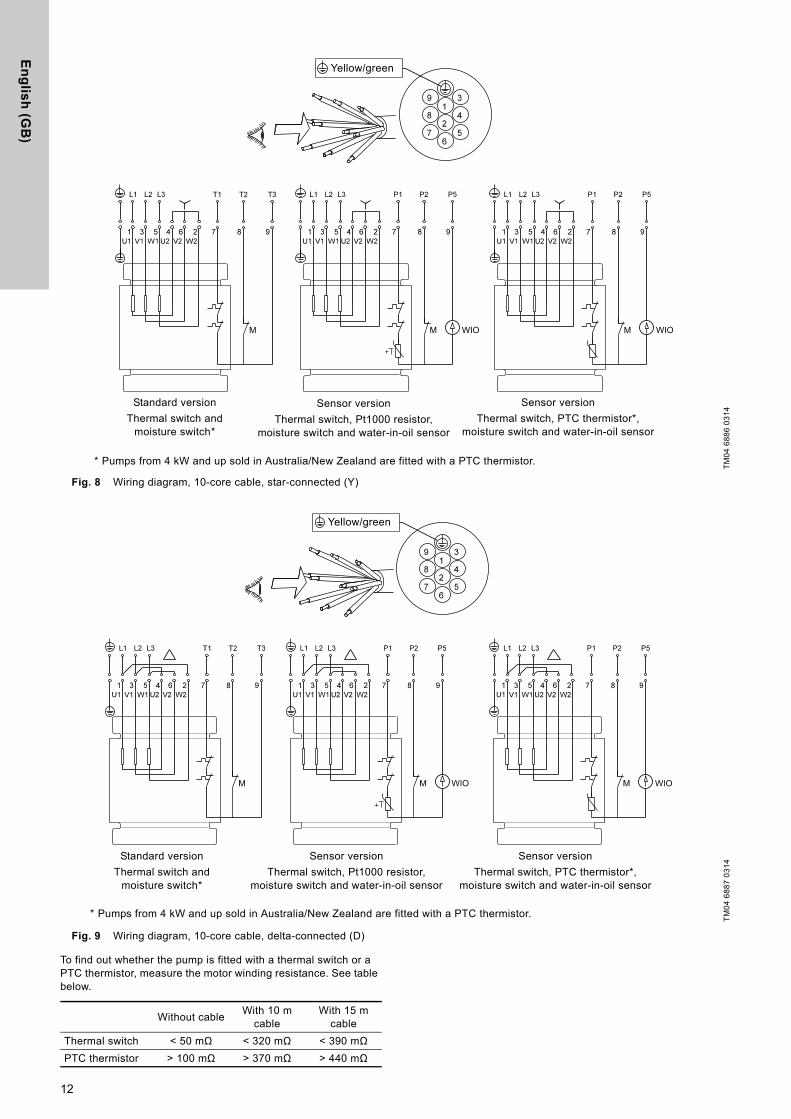
8.1 Wiring diagrams
The pumps are supplied via either a 7-core cable or a 10-core cable. See fig. 6 for wiring diagrams for 7-core cable connection or figs. 7, 8 and 9 for wiring diagrams for 10-core cable connection. For further information, see the installation and operating instructions for the selected control box or pump controller.
Fig. 6 Wiring diagram, 7-core cable, DOL
Fig. 7 Wiring diagram, 10-core cable, star/delta (Y/D)
TM
04
68
84
03
14Standard version
Thermal switch and moisture switch*
Sensor version
Thermal switch, Pt1000 resistor, moisture switch and water-in-oil sensor
Sensor version
Thermal switch, PTC thermistor*, moisture switch and water-in-oil sensor
Yellow/green
* Pumps from 4 kW and up sold in Australia/New Zealand are fitted with a PTC thermistor.
TM
04
68
85
03
14
Yellow/green
Standard version
Thermal switch and moisture switch*
Sensor version
Thermal switch, Pt1000 resistor, moisture switch and water-in-oil sensor
Sensor version
Thermal switch, PTC thermistor*, moisture switch and water-in-oil sensor
* Pumps from 4 kW and up sold in Australia/New Zealand are fitted with a PTC thermistor.
11
En
glis
h (G
B)
Fig. 8 Wiring diagram, 10-core cable, star-connected (Y)
Fig. 9 Wiring diagram, 10-core cable, delta-connected (D)
To find out whether the pump is fitted with a thermal switch or a PTC thermistor, measure the motor winding resistance. See table below.
TM
04
68
86
03
14
Yellow/green
Standard version
Thermal switch and moisture switch*
Sensor version
Thermal switch, Pt1000 resistor, moisture switch and water-in-oil sensor
Sensor version
Thermal switch, PTC thermistor*, moisture switch and water-in-oil sensor
* Pumps from 4 kW and up sold in Australia/New Zealand are fitted with a PTC thermistor.
TM
04
68
87
03
14
Yellow/green
Standard version
Thermal switch and moisture switch*
Sensor version
Thermal switch, Pt1000 resistor, moisture switch and water-in-oil sensor
Sensor version
Thermal switch, PTC thermistor*, moisture switch and water-in-oil sensor
* Pumps from 4 kW and up sold in Australia/New Zealand are fitted with a PTC thermistor.
Without cableWith 10 m
cableWith 15 m
cable
Thermal switch < 50 mΩ < 320 mΩ < 390 mΩPTC thermistor > 100 mΩ > 370 mΩ > 440 mΩ
12

En
gli
sh
(G
B)
8.2 Pump controllers
SL1 and SLV pumps can be connected to the following Grundfos pump controllers for level control:
LC controllers are for one-pump-installations and LCD controllers are for two-pump installations.
• LC 107 and LCD 107 with air bells
• LC 108 and LCD 108 with float switches
• LC 110 and LCD 110 with electrodes
• Grundfos DC and DCD.
For further information on controllers, please see the installation and operation instructions for the selected controller or go to www.grundfos.com.
8.3 Thermal switch, Pt1000 and PTC thermistor
All SL1 and SLV pumps have thermal protection incorporated in the stator windings.
Pumps without sensor
Pumps without sensor have a thermal switch or a PTC thermistor. Via the pump controller safety circuit, the thermal switch will stop the pump by breaking the circuit in case of overtemperature (approx. 150 °C). The thermal switch will reclose the circuit after cooling. For pumps equipped with a PTC thermistor, connect the thermistor to either the PTC relay or the I/O module to break the circuit at 150 °C.
The maximum operating current of the thermal switch is 0.5 A at 500 VAC and cos φ 0.6. The switch must be able to break a coil in the supply circuit.
Pumps with WIO sensor
Pumps with WIO sensor have either a thermal switch and a Pt1000 sensor or a PTC thermistor in the windings, depending on the installation site.
Via the pump controller safety circuit, the thermal switch or the thermistor will stop the pump by breaking the circuit in case of overtemperature (approx. 150 °C). The thermal switch or the thermistor will reclose the circuit after cooling.
The maximum operating current of both the Pt1000 and the thermistor is 1 mA at 24 VDC.
Non-explosion-proof pumps
When closing the circuit after cooling, the thermal protection can restart the pump automatically via the controller. Pumps from 4 kW and up sold in Australia/New Zealand are fitted with a PTC thermistor.
Explosion-proof pumps
8.4 WIO sensor (water-in-oil sensor)
The WIO sensor measures the water content in the oil and converts the value into an analogue current signal. The two sensor conductors are for power supply and for carrying the signal to the IO 113. The sensor measures the water content from 0 to 20 %. It also sends a signal if the water content is outside the normal range (warning), or if there is air in the oil chamber (alarm). The sensor is fitted in a stainless-steel tube for mechanical protection.
Fig. 10 WIO sensor
8.4.1 Fitting the WIO sensor
Fit the sensor next to one of the shaft seal openings. See fig. 10. The sensor must be tilted into the motor's direction of rotation to ensure that oil is led into the sensor. Make sure that the sensor is submerged in the oil.
8.4.2 Technical data
See also the installation and operating instructions for IO 113 on www.grundfos.com.
8.5 Moisture switch
All pumps are fitted with a moisture switch as standard with the moisture switch being connected via the supply cable, see section 8. Electrical connection, and connected to a separate circuit breaker.
The moisture switch is positioned in the bottom of the motor. If there is moisture in the motor, the switch will break the circuit and send a signal to the IO 113.
The moisture switch is non-reversing and must be replaced after use.
The moisture switch is connected to the monitoring cable, and it must be connected to the safety circuit of the separate pump controller. See section 8. Electrical connection.
Warning
The thermal protection of explosion-proof pumps must not restart the pump automatically. This ensures protection against overtemperature in potentially explosive environments. In pumps with sensor this is done by removing the short circuit between terminals R1 and R2 in the IO 113. See Electrical data in the IO 113 installation and operating instructions.
Warning
The separate motor-protective circuit breaker/controller must not be installed in potentially explosive environments.
TM
04
52
38
29
09
- T
M0
3 1
16
4 1
10
5
Input voltage: 12-24 VDC
Output current: 3.4 - 22 mA
Power input: 0.6 W
Ambient temperature: 0-70 °C
Caution
The motor-protective circuit breaker of the pump controller must include a circuit which automatically disconnects the power supply in case the protective circuit for the pump is opened.
13

En
glis
h (G
B)
8.6 IO 113
IO 113 provides an interface between a Grundfos wastewater pump equipped with sensors and the pump controller(s). The most important sensor status information is indicated on the front panel.
One pump can be connected to one IO 113 module.
Together with the sensors, the IO 113 provides a galvanic isolation between the motor voltage in the pump and the connected controller(s).
IO 113 can do the following as standard:
• Protect the pump against overheating.
• Monitor the status of these items:
– motor winding temperature
– leakage (WIO)
– moisture in pump.
• Measure the stator insulation resistance.
• Stop the pump in case of alarm.
• Remotely monitor the pump via RS-485 communication (Modbus or GENIbus).
• Control the pump via a frequency converter.
Fig. 11 IO 113 module
8.7 Frequency converter operation
All SL1/SLV pump types are designed for frequency converter operation to keep the energy consumption at a minimum.
To avoid the risk of sedimentation in the pipes, we recommend that you operate the speed-controlled pump at a flow rate above 1 m/s.
For frequency converter operation, please observe the following information:
• Requirements must be fulfilled. See section 8.7.1 Requirements.
• Recommendations ought to be fulfilled. See section 8.7.2 Recommendations.
• Consequences should be considered. See section 8.7.3 Consequences.
8.7.1 Requirements
• The thermal protection of the motor must be connected.
• Minimum switching frequency: 2.5 kHz.
• Peak voltage and dU/dt must be in accordance with the table below. The values stated are maximum values supplied to the motor terminals. The cable influence has not been taken into account. See the frequency converter data sheet regarding the actual values and the cable influence on the peak voltage and dU/dt.
• If the pump is an Ex-approved pump, check if the Ex certificate of the specific pump allows the use of a frequency converter.
• Set the frequency converter U/f ratio according to the motor data.
• Local regulations/standards must be fulfilled.
8.7.2 Recommendations
Before installing a frequency converter, calculate the lowest allowable frequency in the installation in order to avoid zero flow.
• Do not reduce the motor speed to less than 30 % of rated speed.
• Keep the flow velocity above 1 m/sec.
• Let the pump run at rated speed at least once a day in order to prevent sedimentation in the piping system.
• Do not exceed the frequency indicated on the nameplate. In this case there is risk of motor overload.
• Keep the motor cable as short as possible. The peak voltage will increase with the length of the motor cable. See data sheet for the frequency converter used.
• Use input and output filters on the frequency converter. See data sheet for the frequency converter used.
• Use screened motor cable if there is a risk that electrical noise can disturb other electrical equipment. See data sheet for the frequency converter used.
8.7.3 Consequences
When operating the pump via a frequency converter, please be aware of these possible consequences:
• The locked-rotor torque will be lower. How much lower will depend on the frequency converter type. See the installation and operating instructions for the frequency converter used for information on the locked-rotor torque available.
• The working condition of bearings and shaft seal may be affected. The possible effect will depend on the application. The actual effect cannot be predicted.
• The acoustic noise level may increase. See the installation and operating instructions for the frequency converter used for advice as to how to reduce the acoustic noise.
Warning
IO 113 must not be used for purposes other than those specified above.
TM
05
18
81
38
11
Pos. Description
1 Terminals for alarm relay
2 Terminals for analog and digital inputs and outputs
3 Terminals for supply voltage
4Potentiometer for setting the warning limit of stator insulation resistance
5 Terminals for RS-485 for GENIbus or Modbus
6 Indicator light for moisture measurement
7 Indicator light for stator insulation resistance
8 Indicator light for leakage (WIO)
9 Indicator light for vibration in pump
10Terminals for measurement of stator insulation resistance
11 Terminals for connection of pump sensors
12 DIP switch for configuration
13 Indicator light for motor temperature
14 Button for resetting alarms
15 Indicator light for motor running
16 Indicator light for service
17 Terminals for digital outputs
PET1 T2 G1 A1 G2 A2 K1 K2 R1 R2
D1 D2 D3 D4 D5 D6 D7 D8
P1 P2 P3 P4 P5
A Y B
I1 I2 I3
ON DIP
1 2 3 4 5 6 7 8 9 10 11 12
1 2 3
45
678
9
1011
12
13
14
1615
17
Maximum repetitive peak voltage
[V]
Maximum dU/dtUN 400 V[V/μ sec.]
850 2000
14

En
gli
sh
(G
B)
9. Startup9.1 General startup procedure
This procedure applies to new installations as well as after service inspections if startup takes place some time after the pump was placed in the tank.
1. Remove the fuses and check that the impeller can rotate freely. Turn the impeller by hand.
2. Check the condition of the oil in the oil chamber. See also section 10.1 Inspection.
3. Check that the system, bolts, gaskets, pipework and valves etc. are in correct condition.
4. Mount the pump in the system.
5. Switch on the power supply.
6. Check whether the monitoring units, if used, are operating satisfactorily.
7. For pumps with WIO sensor, switch on the IO 113 and check that there are no alarms or warnings. See section 8.6 IO 113.
8. Check the setting of air bells, float switches or electrodes.
9. Check the direction of rotation. See section 9.3 Direction of rotation.
10. Open the isolating valves, if fitted.
11. Check that the liquid level is above the motor for S1 operation and above the cable entry for S3 operation. See fig. 14. If the minimum level is not reached do not start the pump.
12. Start the pump and let the pump run briefly, and check if the liquid level is falling.
13. Observe if the discharge pressure and input current are normal. If not there might be air trapped inside the pump.
After one week of operation or after replacement of the shaft seal, check the condition of the oil in the chamber. For pumps without sensor, this is done by taking a sample of the oil. See section 10. Maintenance and service for procedure.
Every time the pump has been removed from the tank, go through the above procedure when starting up again.
9.2 Operating modes
The pumps are designed for intermittent operation (S3). When completely submerged, the pumps can also operate continuously (S1).
S3, intermittent operation:
Operating mode S3 means that within 10 minutes the pump must be in operation for 4 minutes and stopped for 6 minutes. See fig. 12.
In this operating mode, the pump is partly submerged in the pumped liquid, i.e. the liquid level reaches at minimum the top of the cable entry on the motor housing. See fig. 2.
Fig. 12 S3, intermittent operation
S1, continuous operation:
In this operating mode, the pump can operate continuously without being stopped for cooling. See fig. 13. Being completely submerged, the pump is sufficiently cooled by the surrounding liquid. See fig. 2.
Fig. 13 S1, continuous operation
Fig. 14 Start and stop levels
Make sure that the effective volume of the tank does not become so low that the number of starts per hour exceeds the maximum permissible number.
Warning
Before starting work on the pump, make sure that the fuses have been removed or the mains switch has been switched off. Make sure that the power supply cannot be accidentally switched on.
Make sure that all protective equipment has been connected correctly.
The pump must not run dry.
Warning
The pump must not be started if the atmosphere in the tank is potentially explosive.
Warning
It may lead to personal injuries or death to open the clamp while the pump is operating.
Warning
The impeller can have sharp edges - wear protective gloves.
NoteTrapped air can be removed from the pump housing by tilting the pump by means of the lifting chain when the pump is in operation.
Caution
In case of abnormal noise or vibrations from the pump, other pump failure or power supply failure or water supply failure, stop the pump immediately. Do not attempt to restart the pump until the cause of the fault has been found and the fault corrected.
TM
04
45
27
15
09
TM
04
45
28
15
09
TM
04
26
54
28
08
Operation
Stop
6 min.4 min.
10 min.
P
t
P
t
Operation
Stop
Start
Stop S1 operation
Alarm
Min. 10 cm
Stop S3 operation
15
En
glis
h (G
B)
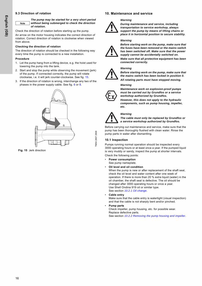
9.3 Direction of rotation
Check the direction of rotation before starting up the pump.
An arrow on the motor housing indicates the correct direction of rotation. Correct direction of rotation is clockwise when viewed from above.
Checking the direction of rotation
The direction of rotation should be checked in the following way every time the pump is connected to a new installation.
Procedure
1. Let the pump hang from a lifting device, e.g. the hoist used for lowering the pump into the tank.
2. Start and stop the pump while observing the movement (jerk) of the pump. If connected correctly, the pump will rotate clockwise, i.e. it will jerk counter-clockwise. See fig. 15.
3. If the direction of rotation is wrong, interchange any two of the phases in the power supply cable. See fig. 6 or 8.
Fig. 15 Jerk direction
10. Maintenance and service
Before carrying out maintenance and service, make sure that the pump has been thoroughly flushed with clean water. Rinse the pump parts in water after dismantling.
10.1 Inspection
Pumps running normal operation should be inspected every 3000 operating hours or at least once a year. If the pumped liquid is very muddy or sandy, inspect the pump at shorter intervals.
Check the following points:
• Power consumption See pump nameplate.
• Oil level and oil conditionWhen the pump is new or after replacement of the shaft seal, check the oil level and water content after one week of operation. If there is more than 20 % extra liquid (water) in the oil chamber, the shaft seal is defective. The oil should be changed after 3000 operating hours or once a year.Use Shell Ondina 919 oil or similar type.See section 10.2.1 Oil change.
• Cable entryMake sure that the cable entry is watertight (visual inspection) and that the cable is not sharply bent and/or pinched.
• Pump partsCheck impeller, pump housing, etc. for possible wear. Replace defective parts.See section 10.2.2 Removing the pump housing and impeller.
NoteThe pump may be started for a very short period without being submerged to check the direction of rotation.
TM
04
26
57
28
08
Warning
During maintenance and service, including transportation to service workshop, always support the pump by means of lifting chains or place it in horizontal position to secure stability.
Warning
Before starting work on the pump, make sure that the fuses have been removed or the mains switch has been switched off. Make sure that the power supply cannot be accidentally switched on.
Make sure that all protective equipment has been connected correctly.
Warning
Before starting work on the pump, make sure that the mains switch has been locked in position 0.
All rotating parts must have stopped moving.
Warning
Maintenance work on explosion-proof pumps must be carried out by Grundfos or a service workshop authorized by Grundfos.
However, this does not apply to the hydraulic components, such as pump housing, impeller, etc.
Warning
The cable must only be replaced by Grundfos or a service workshop authorized by Grundfos.
16

En
gli
sh
(G
B)
• Ball bearingsCheck the shaft for noisy or heavy operation (turn the shaft by hand). Replace defective ball bearings.A general overhaul of the pump is usually required in case of defective ball bearings or poor motor function. This work must be carried out by Grundfos or a service workshop authorized by Grundfos.
• O-rings and similar partsDuring service/replacement, make sure that the grooves for the O-rings as well as the seal faces have been cleaned before the new parts are fitted. Grease O-rings and recesses before assembly.
10.2 Dismantling the pump
10.2.1 Oil change
After 3000 operating hours or once a year, change the oil in the oil chamber as described below.
If the shaft seal has been replaced, the oil must be changed.
Draining of oil
1. Place the pump on a plane surface with one oil screw pointing downwards.
2. Place a suitable container (approx. 1 litre), for instance made of transparent plastic material, under the oil screw.
3. Remove the lower oil screw.
4. Remove the upper oil screw.If the pump has been in operation for a long period of time, if the oil is drained off shortly after the pump has been stopped, and if the oil is greyish white like milk, it contains water. If the oil contains more than 20 % water, it is an indication that the shaft seal is defective and must be replaced. If the shaft seal is not replaced, the motor will be damaged.If the quantity of oil is smaller than the quantity stated in section 10.4 Oil quantities, the shaft seal is defective.
5. Clean the faces for the gaskets for oil screws.
Filling with oil
1. Turn the pump so that the oil filling holes are placed opposite to each other, pointing upwards.
Fig. 16 Oil filling holes
2. Pour oil into the chamber.For oil quantity, see section 10.4 Oil quantities.
3. Fit the oil screws with new gaskets.
10.2.2 Removing the pump housing and impeller
For position numbers, see pages 29 and 30.
Procedure
1. Loosen the clamp (pos. 92).
2. Remove the screw (pos. 92a) using your fingers.
3. Remove the pump housing (pos. 50) by inserting two screwdrivers between the cooling jacket and the pump housing.
4. Remove the screw (pos. 188a). Hold the impeller with a strap wrench.
Fig. 17 Removing the impeller
5. Loosen the impeller (pos. 49) with a light blow on the edge. Pull it off.
6. Remove the key (pos. 9a) and the spring for impeller (pos. 157).
Warning
Defective bearings may reduce the Ex safety.
Note Do not reuse rubber parts.
Warning
Explosion-proof pumps must be checked by an authorized Ex workshop once a year.
Note See www.grundfos.com for service videos.
Warning
When loosening the screws of the oil chamber, note that pressure may have built up in the chamber. Do not remove the screws until the pressure has been fully relieved.
NoteUsed oil must be disposed of in accordance with local regulations.
TM
04
64
77
04
10
TM
04
64
76
04
10
Oil filling/venting
17

En
glis
h (G
B)
10.2.3 Removing the seal ring and wear ring
Procedure
1. Turn the pump housing upside-down.
2. Knock the seal ring (pos. 46) out of the pump housing using a punch.
Fig. 18 Removing the seal ring
3. Clean the pump housing where the seal ring was fitted.
4. Remove the wear ring (pos. 49c) using a screwdriver.
Fig. 19 Removing the wear ring
5. Clean the impeller where the wear ring was fitted.
10.2.4 Removing the shaft seal
Procedure
1. Remove the screws (pos. 188).
2. Remove the cover for oil chamber (pos. 58) using a puller.
3. Remove the screws (pos. 186).
4. Remove the shaft seal (pos. 105) using the puller.
5. Remove the O-ring (pos. 153b).
Procedure (pump with WIO sensor)
1. Remove the screws (pos. 188).
2. Remove the cover for oil chamber (pos. 58) using a puller.
3. Remove the screws (pos. 186).
4. Remove the sensor (pos. 521) and holder (pos. 522) from the shaft seal.
5. Remove the shaft seal (pos. 105) using the puller.
6. Remove the O-ring (pos. 153b).
10.3 Assembling the pump
10.3.1 Tightening torques and lubricants
Rocol Sapphire Aqua-Sil, product number RM2924 (1 kg).
Shell Ondina 919, product number 96001442 (1 l)
10.3.2 Fitting the shaft seal
Procedure
1. Fit and lubricate the O-ring (pos. 153b) with oil.
2. Slide the shaft seal (pos. 105) gently over the shaft.
3. Fit and tighten the screws (pos. 186).
4. Fit and lubricate the O-ring (pos. 107) in the cover for oil chamber (pos. 58) with oil.
5. Fit the cover for oil chamber.
6. Fit and tighten the screws (pos. 188).
Procedure (pump with WIO sensor)
1. Fit and lubricate the O-ring (pos. 153b) with oil.
2. Slide the shaft seal (pos. 105) gently over the shaft.
3. Fit the holder (pos. 522) and sensor (pos. 521) with one of the screws (pos. 186).
4. Fit the second screw and tighten both screws (pos. 186).
5. Fit and lubricate the O-ring (pos. 107) in the cover for oil chamber (pos. 58) with oil.
6. Check that the sensor is positioned correctly. See section 8.4.1 Fitting the WIO sensor and fig. 10. This is of special importance in horizontal pumps.
7. Fit the cover for oil chamber.
8. Fit and tighten the screws (pos. 188).
TM
02
84
20
51
03
TM
02
84
22
51
03
Pos. Designation Quantity Dim.Torque
[Nm]Lubricant
92a Screw 1 12 ± 2
118a Screw 2M8 20 ± 2
M10 30 ± 3
174 Screw 1 4 ± 1
181 Union nut 17-pole 50 ± 5
10-pole 75 ± 5
186 Screw 2 7 + 2-0
182 Screw 4 20 ± 2
187 Screw 4 20 ± 2
188 Screw 2M8 20 ± 2
M10 30 ± 3
188a Screw 2M10 50 + 5-0
M12 75 ± 5
193 Screw 2 16 ± 2
O-rings All Rocol
18
En
gli
sh
(G
B)
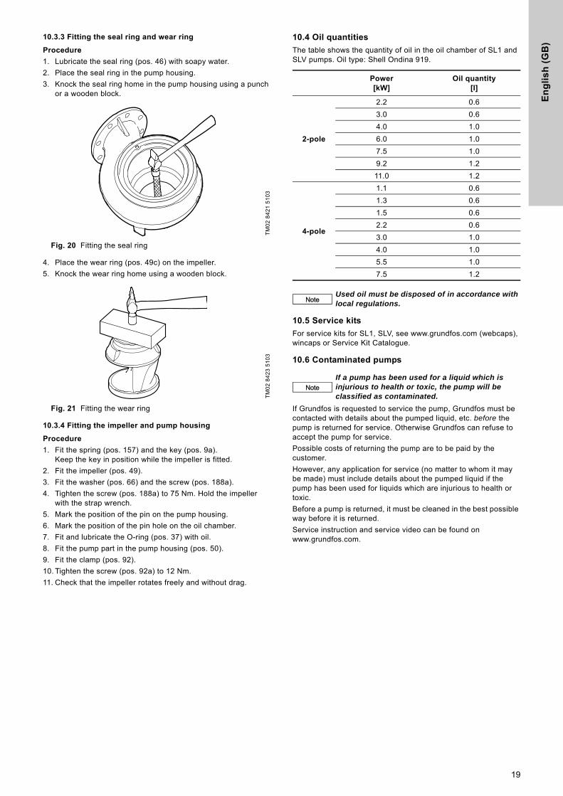
10.3.3 Fitting the seal ring and wear ring
Procedure
1. Lubricate the seal ring (pos. 46) with soapy water.
2. Place the seal ring in the pump housing.
3. Knock the seal ring home in the pump housing using a punch or a wooden block.
Fig. 20 Fitting the seal ring
4. Place the wear ring (pos. 49c) on the impeller.
5. Knock the wear ring home using a wooden block.
Fig. 21 Fitting the wear ring
10.3.4 Fitting the impeller and pump housing
Procedure
1. Fit the spring (pos. 157) and the key (pos. 9a).Keep the key in position while the impeller is fitted.
2. Fit the impeller (pos. 49).
3. Fit the washer (pos. 66) and the screw (pos. 188a).
4. Tighten the screw (pos. 188a) to 75 Nm. Hold the impeller with the strap wrench.
5. Mark the position of the pin on the pump housing.
6. Mark the position of the pin hole on the oil chamber.
7. Fit and lubricate the O-ring (pos. 37) with oil.
8. Fit the pump part in the pump housing (pos. 50).
9. Fit the clamp (pos. 92).
10. Tighten the screw (pos. 92a) to 12 Nm.
11. Check that the impeller rotates freely and without drag.
10.4 Oil quantities
The table shows the quantity of oil in the oil chamber of SL1 and SLV pumps. Oil type: Shell Ondina 919.
10.5 Service kits
For service kits for SL1, SLV, see www.grundfos.com (webcaps), wincaps or Service Kit Catalogue.
10.6 Contaminated pumps
If Grundfos is requested to service the pump, Grundfos must be contacted with details about the pumped liquid, etc. before the pump is returned for service. Otherwise Grundfos can refuse to accept the pump for service.
Possible costs of returning the pump are to be paid by the customer.
However, any application for service (no matter to whom it may be made) must include details about the pumped liquid if the pump has been used for liquids which are injurious to health or toxic.
Before a pump is returned, it must be cleaned in the best possible way before it is returned.
Service instruction and service video can be found on www.grundfos.com.
TM
02
84
21
51
03
TM
02
84
23
51
03
Power[kW]
Oil quantity[l]
2-pole
2.2 0.6
3.0 0.6
4.0 1.0
6.0 1.0
7.5 1.0
9.2 1.2
11.0 1.2
4-pole
1.1 0.6
1.3 0.6
1.5 0.6
2.2 0.6
3.0 1.0
4.0 1.0
5.5 1.0
7.5 1.2
NoteUsed oil must be disposed of in accordance with local regulations.
NoteIf a pump has been used for a liquid which is injurious to health or toxic, the pump will be classified as contaminated.
19

En
glis
h (G
B)
11. Fault finding
* Applies only to pumps with sensor and with IO 113.
Warning
Before attempting to diagnose any fault, make sure that the fuses have been removed or the mains switch has been switched off. Make sure that the power supply cannot be accidentally switched on.
All rotating parts must have stopped moving.
Warning
All regulations applying to pumps installed in potentially explosive environments must be observed.
Make sure that no work is carried out in potentially explosive atmosphere.
NoteFor pumps with sensor, start fault finding by checking the status on the IO 113 front panel.
See installation and operating instructions for IO 113.
Fault Cause Remedy
1. Motor does not start. Fuses blow or motor-protective circuit breaker trips immediately. Caution: Do not start again!
a) Supply failure; short circuit; earth-leakage fault in cable or motor winding.
Have the cable and motor checked and repaired by a qualified electrician.
b) Fuses blow due to use of wrong type of fuse.
Fit fuses of the correct type.
c) Impeller blocked by impurities. Clean the impeller.
d) Air bells, float switches or electrodes out of adjustment or defective.
Readjust or replace the air bells, float switches or electrodes.
e) Moisture in the stator housing (alarm). The IO 113 interrupts the supply voltage.*
Replace the O-rings, the shaft seal and moisture switch.
f) The WIO sensor is not covered by oil (alarm). The IO 113 interrupts the supply voltage.*
Check, and possibly replace, the shaft seal, fill up with oil and reset the IO 113.
g) Stator insulation resistance too low.* Reset alarm on IO 113, see installation and operating instructions for IO 113.
2. Pump operates, but motor-protective circuit breaker trips after a short while.
a) Low setting of thermal relay in motor-protective circuit breaker.
Set the relay in accordance with the specifications on the nameplate.
b) Increased current consumption due to large voltage drop.
Measure the voltage between two motor phases. Tolerance: - 10 %/+ 6 %. Reestablish correct voltage supply.
c) Impeller blocked by impurities.Increased current consumption in all three phases.
Clean the impeller.
d) Wrong direction of rotation. Check the direction of rotation and possibly interchange any two of the phases in the incoming supply cable. See section 9.3 Direction of rotation.
3. The thermal switch of the pump trips after a short while.
a) Too high liquid temperature. Reduce the liquid temperature.
b) Too high viscosity of the pumped liquid. Dilute the pumped liquid.
c) Wrong electrical connection. (If the pump is star-connected to a delta connection, the result will be very low undervoltage).
Check and correct the electrical installation.
4. Pump operates at below-standard performance and power consumption.
a) Impeller blocked by impurities. Clean the impeller.
Check the direction of rotation and possibly interchange any two of the phases in the incoming supply cable. See section 9.3 Direction of rotation.
b) Wrong direction of rotation.
5. Pump operates, but gives no liquid.
a) Discharge valve closed or blocked. Check the discharge valve and possibly open and/or clean it.
b) Non-return valve blocked. Clean the non-return valve.
c) Air in pump. Vent the pump.
6. High power consumption (SLV).
a) Wrong direction of rotation. Check the direction of rotation and possibly interchange any two of the phases in the incoming supply cable. See section 9.3 Direction of rotation.
b) Impeller blocked by impurities. Clean the impeller.
7. Noisy operation and excessive vibrations (SL1).
a) Wrong direction of rotation. Check the direction of rotation and possibly interchange any two of the phases in the incoming supply cable. See section 9.3 Direction of rotation.
b) Impeller blocked by impurities. Clean the impeller.
8. Pump clogged. a) The liquid contains large particles. Select a pump with a larger size of passage.
b) A float layer has formed on the surface of the liquid.
Install a mixer in the tank.
20
En
gli
sh
(G
B)
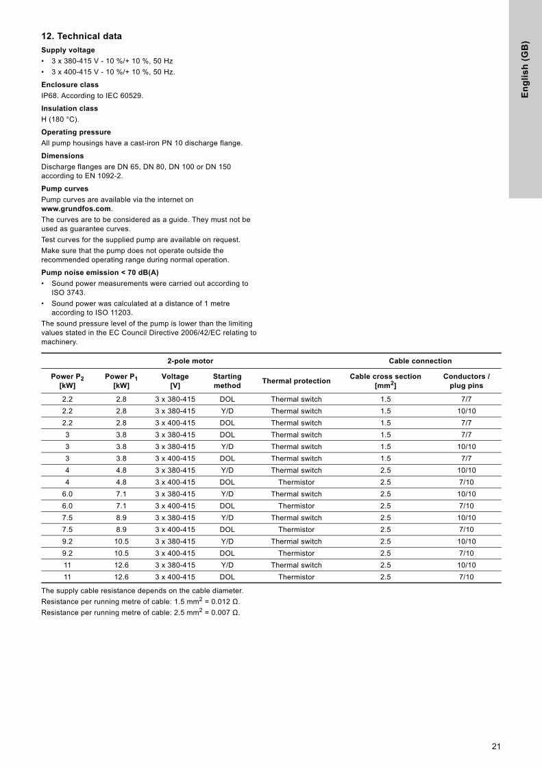
12. Technical dataSupply voltage
• 3 x 380-415 V - 10 %/+ 10 %, 50 Hz
• 3 x 400-415 V - 10 %/+ 10 %, 50 Hz.
Enclosure class
IP68. According to IEC 60529.
Insulation class
H (180 °C).
Operating pressure
All pump housings have a cast-iron PN 10 discharge flange.
Dimensions
Discharge flanges are DN 65, DN 80, DN 100 or DN 150 according to EN 1092-2.
Pump curves
Pump curves are available via the internet on www.grundfos.com.
The curves are to be considered as a guide. They must not be used as guarantee curves.
Test curves for the supplied pump are available on request.
Make sure that the pump does not operate outside the recommended operating range during normal operation.
Pump noise emission < 70 dB(A)
• Sound power measurements were carried out according to ISO 3743.
• Sound power was calculated at a distance of 1 metre according to ISO 11203.
The sound pressure level of the pump is lower than the limiting values stated in the EC Council Directive 2006/42/EC relating to machinery.
The supply cable resistance depends on the cable diameter.
Resistance per running metre of cable: 1.5 mm2 = 0.012 Ω.
Resistance per running metre of cable: 2.5 mm2 = 0.007 Ω.
2-pole motor Cable connection
Power P2[kW]
Power P1[kW]
Voltage[V]
Starting method
Thermal protectionCable cross section
[mm2]Conductors /
plug pins
2.2 2.8 3 x 380-415 DOL Thermal switch 1.5 7/7
2.2 2.8 3 x 380-415 Y/D Thermal switch 1.5 10/10
2.2 2.8 3 x 400-415 DOL Thermal switch 1.5 7/7
3 3.8 3 x 380-415 DOL Thermal switch 1.5 7/7
3 3.8 3 x 380-415 Y/D Thermal switch 1.5 10/10
3 3.8 3 x 400-415 DOL Thermal switch 1.5 7/7
4 4.8 3 x 380-415 Y/D Thermal switch 2.5 10/10
4 4.8 3 x 400-415 DOL Thermistor 2.5 7/10
6.0 7.1 3 x 380-415 Y/D Thermal switch 2.5 10/10
6.0 7.1 3 x 400-415 DOL Thermistor 2.5 7/10
7.5 8.9 3 x 380-415 Y/D Thermal switch 2.5 10/10
7.5 8.9 3 x 400-415 DOL Thermistor 2.5 7/10
9.2 10.5 3 x 380-415 Y/D Thermal switch 2.5 10/10
9.2 10.5 3 x 400-415 DOL Thermistor 2.5 7/10
11 12.6 3 x 380-415 Y/D Thermal switch 2.5 10/10
11 12.6 3 x 400-415 DOL Thermistor 2.5 7/10
21
En
glis
h (G
B)
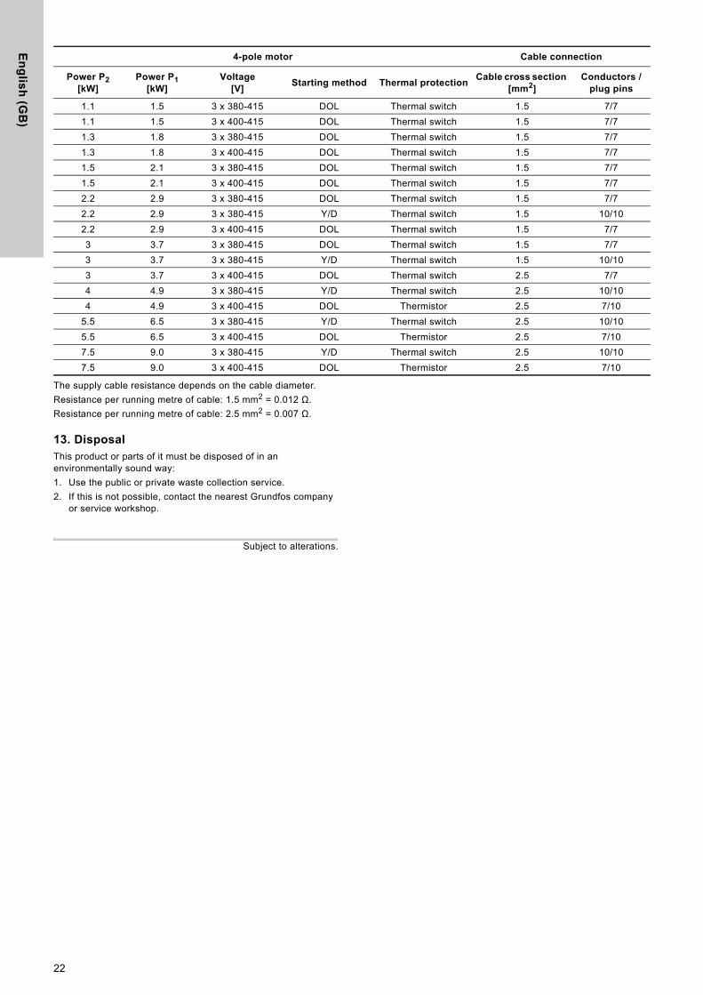
The supply cable resistance depends on the cable diameter.
Resistance per running metre of cable: 1.5 mm2 = 0.012 Ω.
Resistance per running metre of cable: 2.5 mm2 = 0.007 Ω.
13. DisposalThis product or parts of it must be disposed of in an environmentally sound way:
1. Use the public or private waste collection service.
2. If this is not possible, contact the nearest Grundfos company or service workshop.
Subject to alterations.
4-pole motor Cable connection
Power P2[kW]
Power P1[kW]
Voltage[V]
Starting method Thermal protectionCable cross section
[mm2]Conductors /
plug pins
1.1 1.5 3 x 380-415 DOL Thermal switch 1.5 7/7
1.1 1.5 3 x 400-415 DOL Thermal switch 1.5 7/7
1.3 1.8 3 x 380-415 DOL Thermal switch 1.5 7/7
1.3 1.8 3 x 400-415 DOL Thermal switch 1.5 7/7
1.5 2.1 3 x 380-415 DOL Thermal switch 1.5 7/7
1.5 2.1 3 x 400-415 DOL Thermal switch 1.5 7/7
2.2 2.9 3 x 380-415 DOL Thermal switch 1.5 7/7
2.2 2.9 3 x 380-415 Y/D Thermal switch 1.5 10/10
2.2 2.9 3 x 400-415 DOL Thermal switch 1.5 7/7
3 3.7 3 x 380-415 DOL Thermal switch 1.5 7/7
3 3.7 3 x 380-415 Y/D Thermal switch 1.5 10/10
3 3.7 3 x 400-415 DOL Thermal switch 2.5 7/7
4 4.9 3 x 380-415 Y/D Thermal switch 2.5 10/10
4 4.9 3 x 400-415 DOL Thermistor 2.5 7/10
5.5 6.5 3 x 380-415 Y/D Thermal switch 2.5 10/10
5.5 6.5 3 x 400-415 DOL Thermistor 2.5 7/10
7.5 9.0 3 x 380-415 Y/D Thermal switch 2.5 10/10
7.5 9.0 3 x 400-415 DOL Thermistor 2.5 7/10
22

Ap
pe
nd
ix
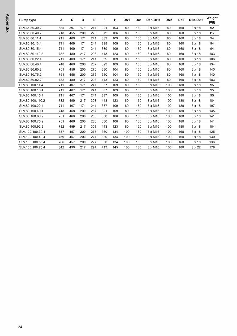
Appendix 11. Dimensions and weights
1.1 Pumps without accessories
TM
04
27
93
30
08
Pump type A C D E F H DN1 Dc1 D1n-D∅1 DN2 Dc2 D2n-D∅2Weight
[kg]
SL1.50.65.22.2 641 366 171 216 321 93 65 145 4 x M16 65 145 4 x 18 86
SL1.50.65.30.2 641 366 171 216 321 93 65 145 4 x M16 65 145 4 x 18 89
SL1.50.65.40.2 677 407 200 227 379 93 65 145 4 x M16 65 145 4 x 18 115
SL1.50.80.22.2 641 366 171 216 321 100 65 145 4 x M16 80 160 8 x 18 87
SL1.50.80.30.2 641 366 171 216 321 100 65 145 4 x M16 80 160 8 x 18 90
SL1.50.80.40.2 677 407 200 227 379 100 65 145 4 x M16 80 160 8 x 18 116
SL1.80.80.15.4 682 435 171 272 347 100 100 180 8 x M16 80 160 8 x 18 95
SL1.80.80.22.4 682 435 171 272 347 100 100 180 8 x M16 80 160 8 x 18 107
SL1.80.80.30.4 711 505 200 319 397 118 100 180 8 x M16 80 160 8 x 18 137
SL1.80.80.40.4 748 505 200 319 397 118 100 180 8 x M16 80 160 8 x 18 142
SL1.80.80.55.4 755 505 200 319 397 118 100 180 8 x M16 80 160 8 x 18 149
SL1.80.80.75.4 818 530 217 328 423 118 100 180 8 x M16 80 160 8 x 18 193
SL1.80.100.15.4 682 435 171 272 347 112 100 180 8 x M16 100 180 8 x 19 96
SL1.80.100.22.4 682 435 171 272 347 112 100 180 8 x M16 100 180 8 x 19 108
SL1.80.100.30.4 726 505 200 319 397 118 100 180 8 x M16 100 180 8 x 19 139
SL1.80.100.40.4 748 505 200 319 397 118 100 180 8 x M16 100 180 8 x 19 143
SL1.80.100.55.4 755 505 200 319 397 118 100 180 8 x M16 100 180 8 x 19 150
SL1.80.100.75.4 818 530 217 328 423 118 100 180 8 x M16 100 180 8 x 19 194
SL1.100.100.40.4 754 541 200 320 438 115 150 240 8 x M20 100 180 8 x 22 155
SL1.100.100.55.4 762 541 200 320 438 115 150 240 8 x M20 100 180 8 x 22 161
SL1.100.100.75.4 827 541 217 312 462 115 150 240 8 x M20 100 180 8 x 22 202
SL1.100.150.40.4 755 541 200 320 440 143 150 240 8 x M20 150 240 8 x 22 157
SL1.100.150.40.4 755 541 200 320 440 143 150 240 8 x M20 150 240 8 x 22 157
SL1.100.150.55.4 762 541 200 320 440 143 150 240 8 x M20 150 240 8 x 22 163
SL1.100.150.75.4 827 541 217 306 472 143 150 240 8 x M20 150 240 8 x 22 204
SLV.65.65.22.2 684 396 171 246 321 102 80 160 8 x M16 65 145 4 x 18 88
SLV.65.65.30.2 684 396 171 246 321 102 80 160 8 x M16 65 145 4 x 18 91
SLV.65.65.40.2 718 456 200 276 380 106 80 160 8 x M16 65 145 4 x 18 117
SLV.65.80.22.2 685 397 171 247 321 103 80 160 8 x M16 80 160 8 x 18 89
23
Ap
pe
nd
ix
SLV.65.80.30.2 685 397 171 247 321 103 80 160 8 x M16 80 160 8 x 18 92SLV.65.80.40.2 718 455 200 276 379 106 80 160 8 x M16 80 160 8 x 18 117
SLV.80.80.11.4 711 409 171 241 339 109 80 160 8 x M16 80 160 8 x 18 94
SLV.80.80.13.4 711 409 171 241 339 109 80 160 8 x M16 80 160 8 x 18 94
SLV.80.80.15.4 711 409 171 241 339 109 80 160 8 x M16 80 160 8 x 18 94
SLV.80.80.110.2 782 489 217 293 413 123 80 160 8 x M16 80 160 8 x 18 183
SLV.80.80.22.4 711 409 171 241 339 109 80 160 8 x M16 80 160 8 x 18 106
SLV.80.80.40.4 748 460 200 267 393 109 80 160 8 x M16 80 160 8 x 18 134
SLV.80.80.60.2 751 456 200 276 380 104 80 160 8 x M16 80 160 8 x 18 140
SLV.80.80.75.2 751 456 200 276 380 104 80 160 8 x M16 80 160 8 x 18 140
SLV.80.80.92.2 782 489 217 293 413 123 80 160 8 x M16 80 160 8 x 18 183
SLV.80.100.11.4 711 407 171 241 337 109 80 160 8 x M16 100 180 8 x 18 95
SLV.80.100.13.4 711 407 171 241 337 109 80 160 8 x M16 100 180 8 x 18 95
SLV.80.100.15.4 711 407 171 241 337 109 80 160 8 x M16 100 180 8 x 18 95
SLV.80.100.110.2 782 499 217 303 413 123 80 160 8 x M16 100 180 8 x 18 184
SLV.80.100.22.4 711 407 171 241 337 109 80 160 8 x M16 100 180 8 x 18 107
SLV.80.100.40.4 748 458 200 267 391 109 80 160 8 x M16 100 180 8 x 18 135
SLV.80.100.60.2 751 466 200 286 380 108 80 160 8 x M16 100 180 8 x 18 141
SLV.80.100.75.2 751 466 200 286 380 108 80 160 8 x M16 100 180 8 x 18 141
SLV.80.100.92.2 782 499 217 303 413 123 80 160 8 x M16 100 180 8 x 18 184
SLV.100.100.30.4 737 457 200 277 380 134 100 180 8 x M16 100 160 8 x 18 125
SLV.100.100.40.4 759 457 200 277 380 134 100 180 8 x M16 100 160 8 x 18 130
SLV.100.100.55.4 766 457 200 277 380 134 100 180 8 x M16 100 160 8 x 18 136
SLV.100.100.75.4 842 490 217 294 413 145 100 180 8 x M16 100 180 8 x 22 179
Pump type A C D E F H DN1 Dc1 D1n-D∅1 DN2 Dc2 D2n-D∅2Weight
[kg]
24
Ap
pe
nd
ix
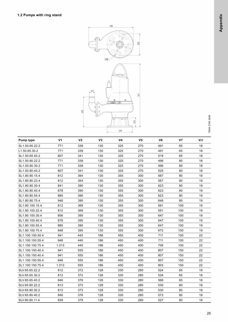
1.2 Pumps with ring standTM
04
27
95
30
08
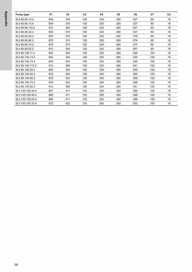
Pump type V1 V2 V3 V4 V5 V6 V7 V∅
SL1.50.65.22.2 771 339 130 325 270 491 65 18
L1.50.65.30.2 771 339 130 325 270 491 65 18
SL1.50.65.40.2 807 341 130 325 270 519 65 18
SL1.50.80.22.2 771 339 130 325 270 496 80 18
SL1.50.80.30.2 771 339 130 325 270 496 80 18
SL1.50.80.40.2 807 341 130 325 270 525 80 18
SL1.80.80.15.4 812 364 130 355 300 567 80 19
SL1.80.80.22.4 812 364 130 355 300 567 80 19
SL1.80.80.30.4 841 390 130 355 300 623 80 19
SL1.80.80.40.4 878 390 130 355 300 623 80 19
SL1.80.80.55.4 885 390 130 355 300 623 80 19
SL1.80.80.75.4 948 390 130 355 300 648 80 19
SL1.80.100.15.4 812 369 130 355 300 591 100 19
SL1.80.100.22.4 812 369 130 355 300 591 100 19
SL1.80.100.30.4 856 395 130 355 300 647 100 19
SL1.80.100.40.4 878 395 130 355 300 647 100 19
SL1.80.100.55.4 885 395 130 355 300 647 100 19
SL1.80.100.75.4 948 395 130 355 300 672 100 19
SL1.100.100.40.4 941 445 186 450 400 711 100 22
SL1.100.100.55.4 948 445 186 450 400 711 100 22
SL1.100.100.75.4 1.013 445 186 450 400 706 100 22
SL1.100.150.40.4 941 555 186 450 400 807 150 22
SL1.100.150.40.4 941 555 186 450 400 807 150 22
SL1.100.150.55.4 948 555 186 450 400 807 150 22
SL1.100.150.75.4 1.013 555 186 450 400 803 150 22
SLV.65.65.22.2 812 372 128 330 280 524 65 18
SLV.65.65.30.2 812 372 128 330 280 524 65 18
SLV.65.65.40.2 846 376 128 330 280 568 65 18
SLV.65.80.22.2 813 373 128 330 280 530 80 18
SLV.65.80.30.2 813 373 128 330 280 530 80 18
SLV.65.80.40.2 846 376 128 330 280 573 80 18
SLV.80.80.11.4 839 379 128 330 280 527 80 18
25
Ap
pe
nd
ix
SLV.80.80.13.4 839 379 128 330 280 527 80 18
SLV.80.80.15.4 839 379 128 330 280 527 80 18
SLV.80.80.110.2 910 393 128 330 280 607 80 18
SLV.80.80.22.4 839 379 128 330 280 527 80 18
SLV.80.80.40.4 876 379 128 330 280 578 80 18
SLV.80.80.60.2 879 374 128 330 280 574 80 18
SLV.80.80.75.2 879 374 128 330 280 574 80 18
SLV.80.80.92.2 910 393 128 330 280 607 80 18
SLV.80.100.11.4 840 354 128 330 280 549 100 18
SLV.80.100.13.4 840 354 128 330 280 549 100 18
SLV.80.100.15.4 840 354 128 330 280 549 100 18
SLV.80.100.110.2 910 368 128 330 280 641 100 18
SLV.80.100.22.4 840 354 128 330 280 549 100 18
SLV.80.100.40.4 876 354 128 330 280 600 100 18
SLV.80.100.60.2 879 353 128 330 280 598 100 18
SLV.80.100.75.2 879 353 128 330 280 598 100 18
SLV.80.100.92.2 910 368 128 330 280 641 100 18
SLV.100.100.30.4 867 411 130 355 300 599 100 19
SLV.100.100.40.4 889 411 130 355 300 599 100 19
SLV.100.100.55.4 896 411 130 355 300 599 100 19
SLV.100.100.75.4 972 422 130 355 300 632 100 19
Pump type V1 V2 V3 V4 V5 V6 V7 V∅
26
Ap
pe
nd
ix
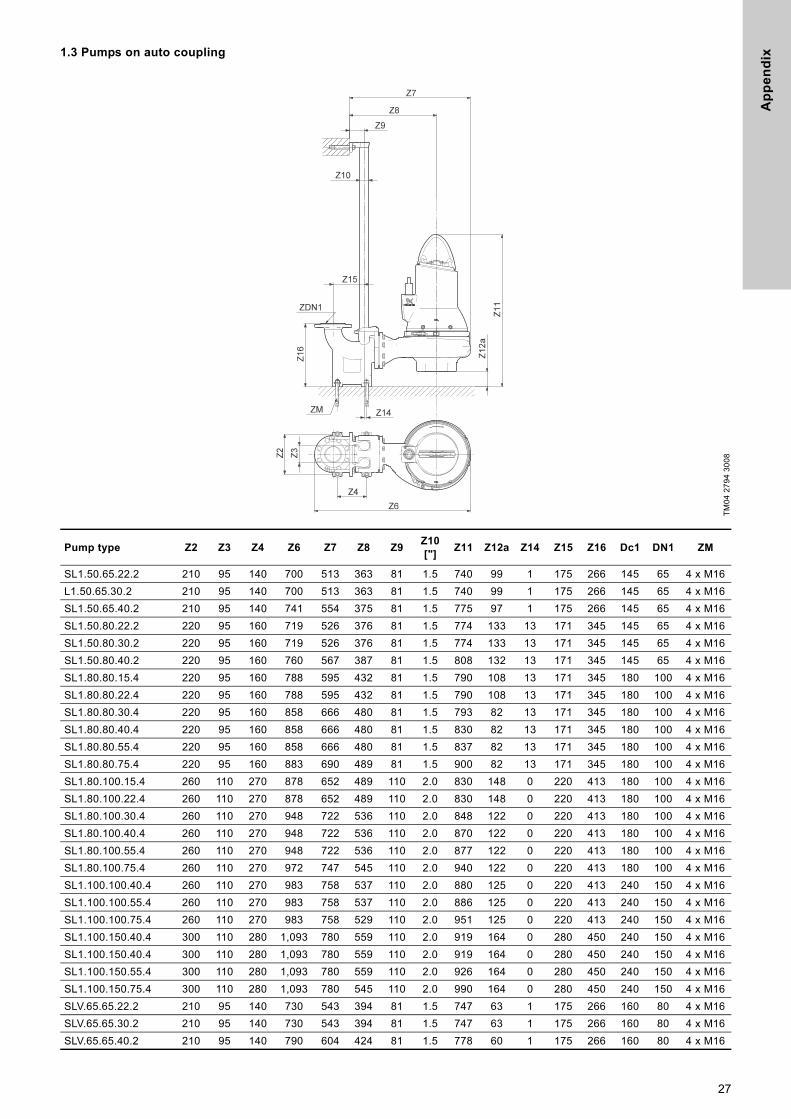
1.3 Pumps on auto couplingTM
04
27
94
30
08
Pump type Z2 Z3 Z4 Z6 Z7 Z8 Z9Z10["]
Z11 Z12a Z14 Z15 Z16 Dc1 DN1 ZM
SL1.50.65.22.2 210 95 140 700 513 363 81 1.5 740 99 1 175 266 145 65 4 x M16
L1.50.65.30.2 210 95 140 700 513 363 81 1.5 740 99 1 175 266 145 65 4 x M16
SL1.50.65.40.2 210 95 140 741 554 375 81 1.5 775 97 1 175 266 145 65 4 x M16
SL1.50.80.22.2 220 95 160 719 526 376 81 1.5 774 133 13 171 345 145 65 4 x M16
SL1.50.80.30.2 220 95 160 719 526 376 81 1.5 774 133 13 171 345 145 65 4 x M16
SL1.50.80.40.2 220 95 160 760 567 387 81 1.5 808 132 13 171 345 145 65 4 x M16
SL1.80.80.15.4 220 95 160 788 595 432 81 1.5 790 108 13 171 345 180 100 4 x M16
SL1.80.80.22.4 220 95 160 788 595 432 81 1.5 790 108 13 171 345 180 100 4 x M16
SL1.80.80.30.4 220 95 160 858 666 480 81 1.5 793 82 13 171 345 180 100 4 x M16
SL1.80.80.40.4 220 95 160 858 666 480 81 1.5 830 82 13 171 345 180 100 4 x M16
SL1.80.80.55.4 220 95 160 858 666 480 81 1.5 837 82 13 171 345 180 100 4 x M16
SL1.80.80.75.4 220 95 160 883 690 489 81 1.5 900 82 13 171 345 180 100 4 x M16
SL1.80.100.15.4 260 110 270 878 652 489 110 2.0 830 148 0 220 413 180 100 4 x M16
SL1.80.100.22.4 260 110 270 878 652 489 110 2.0 830 148 0 220 413 180 100 4 x M16
SL1.80.100.30.4 260 110 270 948 722 536 110 2.0 848 122 0 220 413 180 100 4 x M16
SL1.80.100.40.4 260 110 270 948 722 536 110 2.0 870 122 0 220 413 180 100 4 x M16
SL1.80.100.55.4 260 110 270 948 722 536 110 2.0 877 122 0 220 413 180 100 4 x M16
SL1.80.100.75.4 260 110 270 972 747 545 110 2.0 940 122 0 220 413 180 100 4 x M16
SL1.100.100.40.4 260 110 270 983 758 537 110 2.0 880 125 0 220 413 240 150 4 x M16
SL1.100.100.55.4 260 110 270 983 758 537 110 2.0 886 125 0 220 413 240 150 4 x M16
SL1.100.100.75.4 260 110 270 983 758 529 110 2.0 951 125 0 220 413 240 150 4 x M16
SL1.100.150.40.4 300 110 280 1,093 780 559 110 2.0 919 164 0 280 450 240 150 4 x M16
SL1.100.150.40.4 300 110 280 1,093 780 559 110 2.0 919 164 0 280 450 240 150 4 x M16
SL1.100.150.55.4 300 110 280 1,093 780 559 110 2.0 926 164 0 280 450 240 150 4 x M16
SL1.100.150.75.4 300 110 280 1,093 780 545 110 2.0 990 164 0 280 450 240 150 4 x M16
SLV.65.65.22.2 210 95 140 730 543 394 81 1.5 747 63 1 175 266 160 80 4 x M16
SLV.65.65.30.2 210 95 140 730 543 394 81 1.5 747 63 1 175 266 160 80 4 x M16
SLV.65.65.40.2 210 95 140 790 604 424 81 1.5 778 60 1 175 266 160 80 4 x M16
27

Ap
pe
nd
ix
SLV.65.80.22.2 220 95 160 750 557 408 81 1.5 782 97 13 171 345 160 80 4 x M16SLV.65.80.30.2 220 95 160 750 557 408 81 1.5 782 97 13 171 345 160 80 4 x M16
SLV.65.80.40.2 220 95 160 808 616 437 81 1.5 812 94 13 171 345 160 80 4 x M16
SLV.80.80.11.4 220 95 160 762 569 402 81 1.5 802 91 13 171 345 160 80 4 x M16
SLV.80.80.13.4 220 95 160 762 569 402 81 1.5 802 91 13 171 345 160 80 4 x M16
SLV.80.80.15.4 220 95 160 762 569 402 81 1.5 802 91 13 171 345 160 80 4 x M16
SLV.80.80.110.2 220 95 160 842 650 454 81 1.5 859 77 13 171 345 160 80 4 x M16
SLV.80.80.22.4 220 95 160 762 569 402 81 1.5 802 91 13 171 345 160 80 4 x M16
SLV.80.80.40.4 220 95 160 813 620 428 81 1.5 840 91 13 171 345 160 80 4 x M16
SLV.80.80.60.2 220 95 160 809 617 437 81 1.5 847 96 13 171 345 160 80 4 x M16
SLV.80.80.75.2 220 95 160 809 617 437 81 1.5 847 96 13 171 345 160 80 4 x M16
SLV.80.80.92.2 220 95 160 842 650 454 81 1.5 859 77 13 171 345 160 80 4 x M16
SLV.80.100.11.4 260 110 270 850 624 458 110 2.0 842 131 0 220 413 160 80 4 x M16
SLV.80.100.13.4 260 110 270 850 624 458 110 2.0 842 131 0 220 413 160 80 4 x M16
SLV.80.100.15.4 260 110 270 850 624 458 110 2.0 842 131 0 220 413 160 80 4 x M16
SLV.80.100.110.2 260 110 270 942 716 520 110 2.0 899 117 0 220 413 160 80 4 x M16
SLV.80.100.22.4 260 110 270 850 624 458 110 2.0 842 131 0 220 413 160 80 4 x M16
SLV.80.100.40.4 260 110 270 901 675 484 110 2.0 857 109 0 220 413 160 80 4 x M16
SLV.80.100.60.2 260 110 270 909 683 503 110 2.0 883 132 0 220 413 160 80 4 x M16
SLV.80.100.75.2 260 110 270 909 683 503 110 2.0 883 132 0 220 413 160 80 4 x M16
SLV.80.100.92.2 260 110 270 942 716 520 110 2.0 899 117 0 220 413 160 80 4 x M16
SLV.100.100.30.4 260 110 270 900 674 494 110 2.0 844 106 0 220 413 180 100 4 x M16
SLV.100.100.40.4 260 110 270 900 674 494 110 2.0 865 106 0 220 413 180 100 4 x M16
SLV.100.100.55.4 260 110 270 900 674 494 110 2.0 873 106 0 220 413 180 100 4 x M16
SLV.100.100.75.4 260 110 270 933 707 511 110 2.0 938 95 0 220 413 180 100 4 x M16
Pump type Z2 Z3 Z4 Z6 Z7 Z8 Z9Z10["]
Z11 Z12a Z14 Z15 Z16 Dc1 DN1 ZM
28

Ap
pe
nd
ix
2. Exploded drawingsSLV
TM
06
08
85
111
4
29

Ap
pe
nd
ix
SL1
TM
06
05
73
09
14
30

De
cla
rati
on
of
co
nfo
rmit
y
Declaration of conformity 2GB: EC declaration of conformityWe, Grundfos, declare under our sole responsibility that the products SL1 and SLV, to which this declaration relates, are in conformity with these Council directives on the approximation of the laws of the EC member states:
BG: EC декларация за съответствиеНие, фирма Grundfos, заявяваме с пълна отговорност, че продуктите SL1 и SLV, за които се отнася настоящата декларация, отговарят на следните указания на Съвета за уеднаквяване на правните разпоредби на държавите членки на ЕС:
CZ: ES prohlášení o shoděMy firma Grundfos prohlašujeme na svou plnou odpovědnost, že výrobky SL1 a SLV, na něž se toto prohlášení vztahuje, jsou v souladu s ustanoveními směrnice Rady pro sblížení právních předpisů členských států Evropského společenství v oblastech:
DK: EF-overensstemmelseserklæringVi, Grundfos, erklærer under ansvar at produkterne SL1 og SLV som denne erklæring omhandler, er i overensstemmelse med disse af Rådets direktiver om indbyrdes tilnærmelse til EF-medlemsstaternes lovgivning:
DE: EG-KonformitätserklärungWir, Grundfos, erklären in alleiniger Verantwortung, dass die Produkte SL1 und SLV, auf die sich diese Erklärung bezieht, mit den folgenden Richtlinien des Rates zur Angleichung der Rechtsvorschriften der EU-Mitgliedsstaaten übereinstimmen:
EE: EL vastavusdeklaratsioonMeie, Grundfos, deklareerime enda ainuvastutusel, et tooted SL1 ja SLV, mille kohta käesolev juhend käib, on vastavuses EÜ Nõukogu direktiividega EMÜ liikmesriikide seaduste ühitamise kohta, mis käsitlevad:
GR: ∆ήλωση συμμόρφωσης ECΕμείς, η Grundfos, δηλώνουμε με αποκλειστικά δική μας ευθύνη ότι τα προϊόντα SL1 και SLV στα οποία αναφέρεται η παρούσα δήλωση, συμμορφώνονται με τις εξής Οδηγίες του Συμβουλίου περί προσέγγισης των νομοθεσιών των κρατών μελών της ΕΕ:
ES: Declaración CE de conformidadNosotros, Grundfos, declaramos bajo nuestra entera responsabilidad que los productos SL1 y SLV, a los cuales se refiere esta declaración, están conformes con las Directivas del Consejo en la aproximación de las leyes de las Estados Miembros del EM:
FR: Déclaration de conformité CENous, Grundfos, déclarons sous notre seule responsabilité, que les produits SL1 et SLV, auxquels se réfère cette déclaration, sont conformes aux Directives du Conseil concernant le rapprochement des législations des Etats membres CE relatives aux normes énoncées ci-dessous:
HR: EZ izjava o usklađenostiMi, Grundfos, izjavljujemo pod vlastitom odgovornošću da je proizvod SL1 i SLV, na koji se ova izjava odnosi, u skladu s direktivama ovog Vijeća o usklađivanju zakona država članica EU:
IT: Dichiarazione di conformità CEGrundfos dichiara sotto la sua esclusiva responsabilità che i prodotti SL1 e SLV, ai quali si riferisce questa dichiarazione, sono conformi alle seguenti direttive del Consiglio riguardanti il riavvicinamento delle legislazioni degli Stati membri CE:
KZ: EO сəйкестік туралы мəлімдемеБіз, Grundfos компаниясы, барлық жауапкершілікпен, осы мəлімдемеге қатысты болатын SL1 жəне SLV бұйымы ЕО мүше елдерінің заң шығарушы жарлықтарын үндестіру туралы мына Еуроодақ кеңесінің жарлықтарына сəйкес келетіндігін мəлімдейміз
LV: EK atbilstības deklarācijaSabiedrība GRUNDFOS ar pilnu atbildību dara zināmu, ka produkti SL1 un SLV, uz kuriem attiecas šis paziņojums, atbilst šādām Padomes direktīvām par tuvināšanos EK dalībvalstu likumdošanas normām:
LT: EB atitikties deklaracijaMes, Grundfos, su visa atsakomybe pareiškiame, kad gaminiai SL1 ir SLV, kuriems skirta ši deklaracija, atitinka šias Tarybos Direktyvas dėl Europos Ekonominės Bendrijos šalių narių įstatymų suderinimo:
HU: EK megfelelőségi nyilatkozatMi, a Grundfos, egyedüli felelősséggel kijelentjük, hogy a SL1 és SLV termékek, amelyekre jelen nyilatkozik vonatkozik, megfelelnek az Európai Unió tagállamainak jogi irányelveit összehangoló tanács alábbi előírásainak:
NL: EC overeenkomstigheidsverklaringWij, Grundfos, verklaren geheel onder eigen verantwoordelijkheid dat de producten SL1 en SLV waarop deze verklaring betrekking heeft, in overeenstemming zijn met de Richtlijnen van de Raad in zake de onderlinge aanpassing van de wetgeving van de EG Lidstaten
UA: Декларація відповідності ЄСКомпанія Grundfos заявляє про свою виключну відповідальність за те, що продукти SL1 та SLV, на які поширюється дана декларація, відповідають таким рекомендаціям Ради з уніфікації правових норм країн - членів ЄС:
PL: Deklaracja zgodności WEMy, Grundfos, oświadczamy z pełną odpowiedzialnością, że nasze wyroby SL1 oraz SLV, których deklaracja niniejsza dotyczy, są zgodne z następującymi wytycznymi Rady d/s ujednolicenia przepisów prawnych krajów członkowskich WE:
PT: Declaração de conformidade CEA Grundfos declara sob sua única responsabilidade que os produtos SL1 e SLV, aos quais diz respeito esta declaração, estão em conformidade com as seguintes Directivas do Conselho sobre a aproximação das legislações dos Estados Membros da CE:
RU: Декларация о соответствии ЕСМы, компания Grundfos, со всей ответственностью заявляем, что изделия SL1 и SLV, к которым относится настоящая декларация, соответствуют следующим Директивам Совета Евросоюза об унификации законодательных предписаний стран-членов ЕС:
RO: Declaraţie de conformitate CENoi, Grundfos, declarăm pe propria răspundere că produsele SL1 şi SLV, la care se referă această declaraţie, sunt în conformitate cu aceste Directive de Consiliu asupra armonizării legilor Statelor Membre CE:
SK: Prehlásenie o konformite ESMy firma Grundfos prehlasujeme na svoju plnú zodpovednost', že výrobky SL1 a SLV, na ktoré sa toto prehlásenie vzt'ahuje, sú v súlade s ustanovením smernice Rady pre zblíženie právnych predpisov členských štátov Európskeho spoločenstva v oblastiach:
SI: ES izjava o skladnostiV Grundfosu s polno odgovornostjo izjavljamo, da so naši izdelki SL1 in SLV, na katere se ta izjava nanaša, v skladu z naslednjimi direktivami Sveta o približevanju zakonodaje za izenačevanje pravnih predpisov držav članic ES:
RS: EC deklaracija o usaglašenostiMi, Grundfos, izjavljujemo pod vlastitom odgovornošću da je proizvod SL1 i SLV, na koji se ova izjava odnosi, u skladu sa direktivama Saveta za usklađivanje zakona država članica EU:
FI: EY-vaatimustenmukaisuusvakuutusMe, Grundfos, vakuutamme omalla vastuullamme, että tuotteet SL1 ja SLV, joita tämä vakuutus koskee, ovat EY:n jäsenvaltioiden lainsäädännön yhdenmukaistamiseen tähtäävien Euroopan neuvoston direktiivien vaatimusten mukaisia seuraavasti:
SE: EG-försäkran om överensstämmelseVi, Grundfos, försäkrar under ansvar att produkterna SL1 och SLV, som omfattas av denna försäkran, är i överensstämmelse med rådets direktiv om inbördes närmande till EU-medlemsstaternas lagstiftning, avseende:
TR: EC uygunluk bildirgesiGrundfos olarak bu beyannameye konu olan SL1 ve SLV ürünlerinin, AB Üyesi Ülkelerin kanunlarını birbirine yaklaştırma üzerine Konsey Direktifleriyle uyumlu olduğunun yalnızca bizim sorumluluğumuz altında olduğunu beyan ederiz:
CN: EC 产品合格声明书我们格兰富在我们的全权责任下声明,产品 SL1 和 SLV,即该合格证所指之产品,符合欧共体使其成员国法律趋于一致的以下欧共理事会指令:
31
De
cla
ratio
n o
f co
nfo
rmity
VI: Tuyên bố tuân thủ EC (Hội đồng Châu Âu)Chúng tôi - Grundfos - tuyên bố trong phạm vi trách nhiệm duy nhất của mình rằng các sản phẩm SL1 và SLV mà tuyên bố này có liên quan tuân thủ các chỉ thị Hội đồng sau về việc áp dụng luật pháp của các nước thành viên EC:
— Machinery Directive (2006/42/EC).Standards used: EN 809:1998 + A1:2009, EN 60204-1:2006.
— Low Voltage Directive (2006/95/EC).Applicable when rated power is lower than 2.2 kW.Standards used: EN 60335-1:2002, EN 60335-2-41:2003.
— EMC Directive (2004/108/EC).For sensor versions the following standards are used:EN 55014-1:2006, EN 55014-2:1997.
— Construction Products Directive (89/106/EEC).Standards used: EN 12050-1:2001, EN 12050-2:2000.
— ATEX Directive (94/9/EC).Standards used: EN 60079-0:2012, EN 60079-1:2007, EN 13463-1:2009, EN 13463-5:2011.For sensor versions the following standard is also used: EN 60079-18:2009.Applies only to products intended for use in potentially explosive environments, II 2G, equipped with the separate ATEX approval plate and EC-type examination certificate. Further information, see below.
This EC declaration of conformity is only valid when published as part of the Grundfos installation and operating instructions (publication number 96771279 0414).
Tatabánya, 1st April 2014
Jannek Uldal ChristensenD&E Central Europe Manager
GRUNDFOS Manufacturing Ltd.Sóstó Ipari Park, Holland fasor 15
8000 Székesfehérvár, Hungary
Person authorised to compile technical file and empowered to sign the EC declaration of conformity.
EC-type examination certificate No: KEMA 08ATEX0125X.Notified body: KEMA Quality B.V. No 0344. Utrechtseweg 310, 6812 AR Arnhem, Netherlands.Manufacturer: Grundfos Management A/S, Poul Due Jensens Vej 7, 8850 Bjerringbro, Denmark.
32
De
cla
rati
on
of
co
nfo
rmit
y R
U
33
Declaration of conformity RU 3
Насосы типа SL1, SLV сертифицированы на соответствие требованиям Технических регламентов Таможенного союза: ТР ТС 004/2011 «О безопасности низковольтного оборудования»; ТР ТС 010/2011 «О безопасности машин и оборудования»; ТР ТС 020/2011 «Электромагнитная совместимость технических средств».
Сертификат соответствия:№ TC RU C-DK.АИ30.B.01357, срок действия до 18.02.2020г.
Истра, 1 марта 2015 г.
Касаткина В. В.Руководитель отдела качества,
экологии и охраны трудаООО Грундфос Истра, Россия143581, Московская область,
Истринский район,дер. Лешково, д.188
De
cla
ratio
n o
f pe
rform
an
ce
Declaration of performance 4
GB:EU declaration of performance in accordance with Annex III
of Regulation (EU) No 305/2011 (Construction Product Regulation)
1. Unique identification code of the product type: – EN 12050-1 or EN 12050-2 (SL1.50).
2. Type, batch or serial number or any other element allowing identification of the construction product as required pursuant to Article 11(4):– SL1, SLV pumps marked with EN 12050-1 or EN 12050-2 (SL1.50)
on the nameplate.3. Intended use or uses of the construction product, in accordance with
the applicable harmonised technical specification, as foreseen by the manufacturer: – Pumps for pumping of wastewater containing faecal matter marked
with EN 12050-1 on the nameplate.– SL1.50 pumps for pumping of faecal-free wastewater marked with
EN 12050-2 on the nameplate.4. Name, registered trade name or registered trade mark and contact
address of the manufacturer as required pursuant to Article 11(5): – Grundfos Holding A/S
Poul Due Jensens Vej 78850 BjerringbroDenmark.
5. NOT RELEVANT.6. System or systems of assessment and verification of constancy of
performance of the construction product as set out in Annex V: – System 3.
7. In case of the declaration of performance concerning a construction product covered by a harmonised standard:– TÜV Rheinland LGA Products GmbH, identification number: 0197.
Performed test according to EN 12050-1 or EN 12050-2 (SL1.50) under system 3.(description of the third party tasks as set out in Annex V)
– Certificate number: LGA-Certificate No 7381115. Type-tested and monitored.
8. NOT RELEVANT.9. Declared performance:
The products covered by this declaration of performance are in compliance with the essential characteristics and the performance requirements as described in the following:– Standards used: EN 12050-1:2001 or EN 12050-2:2000 (SL1.50).
10. The performance of the product identified in points 1 and 2 is in conformity with the declared performance in point 9.
BG:Декларация на ЕC за изпълнение съгласно Анекс III на
регламент (ЕС) № 305/2011(Регламент за строителните продукти)
1. Уникален идентификационен код на типа продукт:– EN 12050-1 или EN 12050-2 (SL1.50).
2. Типов, партиден или сериен номер на всеки друг елемент, позволяващ идентификация на строителния продукт, изисквана съгласно Член 11(4):– Помпи SL1, SLV, означени с EN 12050-1 или EN 12050-2 (SL1.50) на табелата с данни.
3. Употреба или употреби по предназначение на строителния продукт, в съответствие с приложимата хармонизирана техническа спецификация, както е предвидено от производителя:– Помпи за изпомпване на отпадни води, съдържащи фекални вещества, означени с EN 12050-1 на табелата с данни.
– Помпи SL1.50 за изпомпване на отпадни води без фекални вещества, означени с EN 12050-2 на табелата с данни.
4. Име, запазено търговско име или запазена търговска марка и адрес за контакт на производителя, както се изисква съгласно Член 11(5):– Grundfos Holding A/S
Poul Due Jensens Vej 78850 BjerringbroДания.
5. НЕ СЕ ОТНАСЯ ЗА СЛУЧАЯ.6. Система или системи за оценка и проверка на устойчивостта на
изпълнението на строителния продукт, както е изложено в Анекс V:– Система 3.
7. В случай на декларация за изпълнение, отнасяща се за строителен продукт, който попада в обсега на хармонизиран стандарт:– TÜV Rheinland LGA Products GmbH, идентификационен номер:
0197.Изпълнен тест в съответствие с EN 12050-1 или EN 12050-2 (SL1.50) съгласно система 3.(описание на задачи на трети лица, както е изложено в Анекс V)
– Номер на сертификат: LGA сертификат № 7381115. Тестван за тип и наблюдаван.
8. НЕ СЕ ОТНАСЯ ЗА СЛУЧАЯ.9. Декларирано изпълнение:
Продуктите, предмет на тази декларация за изпълнение, са в съответствие с основните характеристики и изисквания за изпълнение, описани по-долу:– Приложени стандарти: EN 12050-1:2001 или EN 12050-2:2000.
10.Изпълнението на продукта, посочен в точки 1 и 2, е в съответствие с декларираното изпълнение в точка 9.
34
De
cla
rati
on
of
pe
rfo
rma
nc
e
CZ:Prohlášení o vlastnostech EU v souladu s Dodatkem IIIpředpisu (EU) č. 305/2011(Předpis pro stavební výrobky)
1. Jedinečný identifikační kód typu výrobku:– EN 12050-1 nebo EN 12050-2 (SL1.50).
2. Typ, dávka nebo výrobní číslo nebo jakýkoliv prvek umožňující identifikaci stavebního výrobku podle požadavku Článku 11(4):– Čerpadla SL1, SLV s označením EN 12050-1 nebo EN 12050-2
(SL1.50) na typovém štítku.3. Zamýšlená použití stavebního výrobku v souladu s příslušnou
harmonizovanou technickou specifikací výrobce:– Čerpací stanice odpadních vod s fekáliemi s označením EN 12050-
1 na typovém štítku.– Čerpací stanice SL1.50 odpadních vod s fekáliemi s označením
EN 12050-2 na typovém štítku.4. Název, registrovaný obchodní název nebo registrovaná ochranná
známka a kontaktní adresa výrobce podle požadavku Článku 11(5):– Grundfos Holding A/S
Poul Due Jensens Vej 78850 BjerringbroDánsko.
5. NESOUVISÍ.6. Systém nebo systémy posuzování a ověřování stálosti vlastností
stavebního výrobku podle ustanovení Dodatku V:– Systém 3.
7. V případě prohlášení o vlastnostech stavebního výrobku zahrnutého v harmonizované normě:– TÜV Rheinland LGA Products GmbH, identifikační číslo: 0197.
Proveden test podle EN 12050-1 nebo EN 12050-2 (SL1.50) v systému 3.(popis úkolů třetí strany podle ustanovení Dodatku V)
– Číslo certifikátu: Certifikát LGA č. 7381115. Typ testován a monitorován.
8. NESOUVISÍ.9. Prohlašované vlastnosti:
Výrobky uvedené v tomto Prohlášení o vlastnostech jsou v souladu se základními charakteristikami a požadavky na vlastnosti, jak je popsáno níže:– Použité normy: EN 12050-1:2001 nebo EN 12050-2:2000 (SL1.50).
10. Vlastnosti výrobku uvedeného v bodech 1 a 2 v souladu s prohlašovanými vlastnostmi v bodě 9.
DK:EU-ydeevnedeklaration i henhold til bilag III af forordning
(EU) nr. 305/2011(Byggevareforordningen)
1. Varetypens unikke identifikationskode:– EN 12050-1 eller EN 12050-2 (SL1.50).
2. Type-, parti- eller serienummer eller en anden form for angivelse ved hjælp af hvilken byggevaren kan identificeres som krævet i henhold til artikel 11, stk. 4:– SL1-, SLV-pumper der er mærket med EN 12050-1 eller EN 12050-2
(SL1.50) på typeskiltet.3. Byggevarens tilsigtede anvendelse eller anvendelser i
overensstemmelse med den gældende harmoniserede tekniske specifikation som påtænkt af fabrikanten:– Pumper til pumpning af spildevand med fækalier der er mærket med
EN 12050-1 på typeskiltet.– SL1.50-pumper til pumpning af fækaliefrit spildevand der er mærket
med EN 12050-2 på typeskiltet.4. Fabrikantens navn, registrerede firmabetegnelse eller registrerede
varemærke og kontaktadresse som krævet i henhold til artikel 11, stk. 5:– Grundfos Holding A/S
Poul Due Jensens Vej 78850 BjerringbroDanmark.
5. IKKE RELEVANT.6. Systemet eller systemerne til vurdering og kontrol af at byggevarens
ydeevne er konstant, jf. bilag V:– System 3.
7. Hvis ydeevnedeklarationen vedrører en byggevare der er omfattet af en harmoniseret standard:– TÜV Rheinland LGA Products GmbH, identifikationsnummer: 0197.
Udført test i henhold til EN 12050-1 eller EN 12050-2 (SL1.50) efter system 3(beskrivelse af tredjepartsopgaverne, jf. bilag V).
– Certifikatnummer: LGA-certifikat nr. 7381115. Typetestet og overvåget.
8. IKKE RELEVANT.9. Deklareret ydeevne:
De produkter der er omfattet af denne ydeevnedeklaration, er i overensstemmelse med de væsentlige egenskaber og ydelseskrav der er beskrevet i følgende:– Anvendte standarder: EN 12050-1:2001 eller EN 12050-2:2000
(SL1.50).10. Ydeevnen for den byggevare der er anført i punkt 1 og 2, er i
overensstemmelse med den deklarerede ydeevne i punkt 9.
35

De
cla
ratio
n o
f pe
rform
an
ce
DE:EU-Leistungserklärung gemäß Anhang III der Verordnung
(EU) Nr. 305/2011(Bauprodukte-Verordnung)
1. Einmalige Kennnummer des Produkttyps:– EN 12050-1 oder EN 12050-2 (SL1.50).
2. Typ, Charge, Seriennummer oder jedes andere Element, das eine Identifizierung des Bauprodukts erlaubt, wie in Artikel 11 (4) vorgeschrieben.– SL1-, SLV-Pumpen, auf dem Typenschild mit EN 12050-1 oder
EN 12050-2 (SL1.50) gekennzeichnet.3. Verwendungszweck oder Verwendungszwecke des Bauprodukts,
gemäß den geltenden harmonisierten technischen Spezifikationen, wie vom Hersteller vorgesehen:– Pumpen für die Förderung von fäkalienhaltigem Abwasser, auf dem
Typenschild mit EN 12050-1 gekennzeichnet.– SL1.50-Pumpen für die Förderung von fäkalienfreiem Abwasser,
auf dem Typenschild mit EN 12050-2 gekennzeichnet.4. es Warenzeichen und Kontaktanschrift des Herstellers, wie in Artikel
11(5) vorgeschrieben.– Grundfos Holding A/S
Poul Due Jensens Vej 78850 BjerringbroDänemark
5. NICHT RELEVANT.6. System oder Systeme zur Bewertung und Überprüfung der
Leistungsbeständigkeit des Bauprodukts gemäß Anhang V: – System 3.
7. Bei der Leistungserklärung bezüglich eines von einer harmonisierten Norm erfassten Bauprodukts:– TÜV Rheinland LGA Products GmbH, Kennnummer: 0197.
Vorgenommene Prüfung gemäß EN 12050-1 oder EN 12050-2 (SL1.50) unter Anwendung von System 3.(Beschreibung der Aufgaben von unabhängigen Dritten gemäß Anhang V)
– Zertifikatnummer: LGA-Zertifikatnr. 7381115. Typgeprüft und überwacht.
8. NICHT RELEVANT.9. Erklärte Leistung:
Die von dieser Leistungserklärung erfassten Produkte entsprechen den grundlegenden Charakteristika und Leistungsanforderungen, wie im Folgenden beschrieben:– Angewendete Normen: EN 12050-1:2001 oder EN 12050-2:2000
(SL12.50).10. Die Leistung des in Punkt 1 und 2 genannten Produkts entspricht der
in Punkt 9 erklärten Leistung.
EE:EU toimivusdeklaratsioon on kooskõlas EU normatiivi nr.
305/2011 Lisa III(Ehitustoote normid)
1. Toote tüübi ainulaadne identifiseerimis kood:– EN 12050-1 või EN 12050-2 (SL1.50).
2. Tüübi-, partii- või tootenumber või mõni teine element mis võimaldab kindlaks teha, et ehitustoode vastab artikli 11(4):– SL1, SLV pumpadel on andmeplaadil märgistus EN 12050-1 või
EN 12050-2 (SL1.50).3. Ehitustooted on ettenähtud kasutamiseks vastavalt tootja poolt
etteantud kasutusaladel järgides tehnilisi ettekirjutusi.– Andmeplaadil märgitud EN 12050-1 pumbad on mõeldud fekaale
sisaldava heitvee pumpamiseks.– Andmeplaadil märgitud EN 12050-2 (SL1.50) pumplad on mõeldud
fekaale mittesisaldava heitvee pumpamiseks.4. Nimetus, registreeritud kaubamärk või registreeritud kaubamärk ja
kontaktaadress tootjafirmast peavad olema vastavuses Artikkel 11(5):– Grundfos Holding A/S
Poul Due Jensens Vej 78850 BjerringbroTaani.
5. POLE OLULINE.6. Süsteemi või süsteemi hindamine ja kinnitamine püsiva jõudlusega
ehitustooteks nagu on kirjas Lisa V:– Süsteem 3.
7. Toimivusdeklaratsioon järgib ehitustoodete standarditest:– TÜV Rheinland LGA Products GmbH, indentifitseerimis number:
0197.Testitud vastavalt EN 12050-1 või EN 12050-2 (SL1.50) järgi süsteem 3.(kolmandate osapoolte ülesanded nagu on kirjas Lisa V)
– Sertifikaadi number: LGA-Sertifikaadi Nr 7381115. Tüüptestitud ja jälgitud.
8. POLE OLULINE.9. Avaldatud jõudlus:
Toode, mille kohta antud toimivusdeklaratsioon kehtib, on vastavuses põhiomadustega ja jõudlus vajadustega nagu järgnevalt kirjutatud:– Kasutatud standardid: EN 12050-1:2001 või EN 12050-2:2000
(SL1.50).10. Toote tuvastatud jõudlus punktides 1 ja 2 on vastavuses
toimivusdeklaratsiooni punkti 9.
36

De
cla
rati
on
of
pe
rfo
rma
nc
e
GR:∆ήλωση απόδοσης ΕE σύμφωνα με το Παράρτημα ΙΙΙ τουΚανονισμού (ΕΕ) Αρ. 305/2011(Κανονισμός για Προϊόντα του Τομέα ∆ομικών
Κατασκευών)
1. Μοναδικός κωδικός ταυτοποίησης του τύπου του προϊόντος:– EN 12050-1 ή EN 12050-2 (SL1.50).
2. Αριθμός τύπου, παρτίδας ή σειράς ή οποιοδήποτε άλλο στοιχείο επιτρέπει την ταυτοποίηση του προϊόντος του τομέα των δομικών κατασκευών όπως απαιτείται δυνάμει του Άρθρου 11(4): – Αντλίες SL1, SLV με σήμανση EN 12050-1 ή EN 12050-2 (SL1.50) στην πινακίδα.
3. Προτεινόμενη χρήση ή χρήσεις του προϊόντος του τομέα δομικών κατασκευών, σύμφωνα με την ισχύουσα εναρμονισμένη τεχνική προδιαγραφή, όπως προβλέπεται από τον κατασκευαστή:– Αντλίες για άντληση ακάθαρτων υδάτων που περιέχουν περιττώματα με σήμανση EN 12050-1 στην πινακίδα.
– Αντλίες SL1.50 για άντληση ακάθαρτων υδάτων χωρίς περιττώματα με σήμανση EN 12050-2 στην πινακίδα.
4. Όνομα, εμπορική επωνυμία ή σήμα κατατεθέν και διεύθυνση επικοινωνίας του κατασκευαστή όπως απαιτείται δυνάμει του Άρθρου 11(5):– Grundfos Holding A/S
Poul Due Jensens Vej 78850 Bjerringbro∆ανία.
5. ΜΗ ΣΧΕΤΙΚΟ.6. Σύστημα ή συστήματα αξιολόγησης και επαλήθευσης της
σταθερότητας της απόδοσης του προϊόντος του τομέα δομικών κατασκευών όπως καθορίζεται στο Παράρτημα V:– Σύστημα 3.
7. Σε περίπτωση δήλωσης απόδοσης που αφορά προϊόν του τομέα δομικών κατασκευών το οποίο καλύπτεται από ?εναρμονισμένο πρότυπο:– TÜV Rheinland LGA Products GmbH, αριθμός ταυτοποίησης: 0197.∆ιενήργησε δοκιμή σύμφωνα με τα EN 12050-1 ή EN 12050-2 (SL1.50) βάσει του συστήματος 3.(περιγραφή των καθηκόντων του τρίτου μέρους όπως καθορίζονται στο Παράρτημα V)
– Αριθμός πιστοποιητικού: Πιστοποιητικό LGA Αρ. 7381115. Έχει υποβληθεί σε δοκιμή τύπου και παρακολουθείται.
8. ΜΗ ΣΧΕΤΙΚΟ.9. ∆ηλωθείσα απόδοση:
Τα προϊόντα που καλύπτονται από την παρούσα δήλωση απόδοσης συμμορφώνονται με τα ουσιώδη χαρακτηριστικά και τις απαιτήσεις απόδοσης όπως περιγράφεται στα ακόλουθα:– Πρότυπα που χρησιμοποιήθηκαν: EN 12050-1:2001 ή EN 12050-
2:2000 (SL1.50).10.Η απόδοση του προϊόντος που ταυτοποιήθηκε στα σημεία 1 και 2
συμμορφώνεται με τη δηλωθείσα απόδοση στο σημείο 9.
ES:Declaración UE de prestaciones conforme al Anexo III del
Reglamento (UE) n.° 305/2011(Reglamento de productos de construcción)
1. Código de identificación único del tipo de producto:– EN 12050-1 o EN 12050-2 (SL1.50).
2. Tipo, lote o número de serie, o cualquier otro elemento que facilite la identificación del producto de construcción de acuerdo con los requisitos establecidos en el Artículo 11(4):– Bombas SL1, SLV en cuya placa de características figure la norma
EN 12050-1 o EN 12050-2 (SL1.50).3. Uso o usos previstos del producto de construcción, conforme a la
especificación técnica armonizada correspondiente, según lo previsto por el fabricante:– Bombas para el bombeo de aguas residuales que contengan
materia fecal en cuya placa de características figure la norma EN 12050-1.
– Bombas SL1.50 para el bombeo de aguas residuales que contengan materia fecal en cuya placa de características figure la norma EN 12050-2.
4. Nombre, nombre comercial registrado o marca comercial registrada y domicilio de contacto del fabricante de acuerdo con los requisitos establecidos en el Artículo 11(5):– Grundfos Holding A/S
Poul Due Jensens Vej 78850 BjerringbroDinamarca.
5. NO CORRESPONDE.6. Sistema o sistemas de evaluación y verificación de la continuidad de
las prestaciones del producto de construcción, de acuerdo con lo establecido en el Anexo V.– Sistema 3.
7. Si la declaración de prestaciones concierne a un producto de construcción cubierto por una norma armonizada:– TÜV Rheinland LGA Products GmbH, número de identificación:
0197.Ensayo ejecutado según las normas EN 12050-1 o EN 12050-2 (SL1.50), sistema 3.(Descripción de las tareas de las que deben responsabilizarse otras partes de acuerdo con lo establecido en el Anexo V).
– Número de certificado: Certificado LGA n.° 7381115. Tipo sometido a ensayo y monitorizado.
8. NO CORRESPONDE.9. Prestaciones declaradas:
Los productos que cubre esta declaración de prestaciones satisfacen las características fundamentales y requisitos en materia de prestaciones descritos en:– Normas aplicadas: EN 12050-1:2001 o EN 12050-2:2000 (SL1.50).
10. Las prestaciones del producto indicado en los puntos 1 y 2 cumplen lo declarado en el punto 9.
37
De
cla
ratio
n o
f pe
rform
an
ce
FR:Déclaration des performances UE conformément à
l'Annexe III du Règlement (UE) n° 305/2011(Règlement Produits de Construction)
1. Code d'identification unique du type de produit :– EN 12050-1 ou EN 12050-2 (SL1.50).
2. Numéro de type, de lot ou de série ou tout autre élément permettant l'identification du produit de construction comme l'exige l'Article 11(4) :– Pompes SL1, SLV marquées EN 12050-1 ou EN 12050-2 (SL1.50)
sur la plaque signalétique.3. Usage(s) prévu(s) du produit de construction conformément à la spé-
cification technique harmonisée applicable comme indiqué par le fabricant :– Pompe pour la collecte des effluents contenant des matières
fécales marquées EN 12050-1 sur la plaque signalétique.– Pompe SL1.50 pour la collecte des effluents exempts de matières
fécales marquées EN 12050-2 sur la plaque signalétique.4. Nom, nom de commerce déposé ou marque commerciale déposée et
adresse du fabricant comme l'exige l'Article 11(5) :– Grundfos Holding A/S
Poul Due Jensens Vej 78850 BjerringbroDanemark.
5. NON APPLICABLE.6. Système ou systèmes d'attestation et de vérification de la constance
des performances du produit de construction comme stipulé dans l'Annexe V :– Système 3.
7. En cas de déclaration des performances d'un produit de construction couvert par une norme harmonisée :– TÜV Rheinland LGA Products GmbH, numéro d'identification :
0197.Test effectué conformément aux normes EN 12050-1 ou EN 12050-2 (SL1.50) selon le système 3.(description des tâches de tierce partie comme stipulé dans l'Annexe V)
– Numéro de certificat : Certificat LGA n° 7381115. Contrôlé et homologué.
8. NON APPLICABLE.9. Performances déclarées :
Les produits couverts par cette déclaration des performances sont conformes aux caractéristiques essentielles et aux exigences de performances décrites par la suite :– Normes utilisées : EN 12050-1:2001 ou EN 12050-2:2000 (SL1.50).
10. Les performances du produit identifié aux points 1 et 2 sont conformes aux performances déclarées au point 9.
HR:Izjava EU o izjavi u skladu s aneksom III uredbe (EU) br.
305/2011(Uredba za građevinske proizvode)
1. Jedinstveni identifikacijski kod vrste proizvoda:– EN 12050-1 ili EN 12050-2 (SL1.50).
2. Vrsta, broj serije, serijski broj ili bilo koji drugi element koji omogućuje identificiranje građevinskog proizvoda u skladu sa člankom 11(4):– SL1, SLV crpke označene s EN 12050-1 ili EN 12050-2 (SL1.50) na
natpisnoj pločici.3. Namjena ili uporabe građevinskog proizvoda u skladu s primjenjivim
harmoniziranim tehničkim specifikacijama, kao što je predvidio proizvođač:– Crpke za ispumpavanje otpadnih voda s fekalijama, označene s
EN 12050-1 na natpisnoj pločici.– SL1.50 crpke za ispumpavanje otpadnih voda bez fekalija,
označene s EN 12050-2 na natpisnoj pločici.4. Naziv, registrirani trgovački naziv ili registrirani zaštitni znak i adresa
za kontaktiranje proizvođača u skladu sa člankom 11(5):– Grundfos Holding A/S
Poul Due Jensens Vej 78850 BjerringbroDanska.
5. NIJE RELEVANTNO.6. Procjena jednog ili više sustava i provjera stalnosti rada građevinskog
proizvoda, kao što je određeno aneksom V:– Sustav 3.
7. U slučaju izjave o izvedbi za građevinski proizvod pokriven harmoniziranim standardom:– TÜV Rheinland LGA Products GmbH, identifikacijski broj: 0197.
Izvršite ispitivanje u skladu s EN 12050-1 ili EN 12050-2 (SL1.50) u okviru sustava 3.(Opis zadataka trećih strana, kao što je definirano aneksom V)
– Broj certifikata: Br. LGA certifikata 7381115. Ispitana vrsta i nadzirano.
8. NIJE RELEVANTNO.9. Izjavljena izvedba:
Proizvodi obuhvaćeni ovom izjavom o izvedbi u skladu su s osnovnim karakteristikama i zahtjevima za izvedbu, kao što je definirano u nastavku:– Uporabljeni standardi: EN 12050-1:2001 ili EN 12050-2:2000
(SL1.50).10. Izvedba proizvoda identificirana u točkama 1 i 2 u skladu je s
izjavljenom izvedbom u točki 9.
38
De
cla
rati
on
of
pe
rfo
rma
nc
e
IT:Dichiarazione UE di prestazioni in conformità all'all. III delRegolamento (UE) n. 305/2011(regolamento sui prodotti da costruzione)
1. Codice identificativo esclusivo del tipo di prodotto:– EN 12050-1 oppure EN 12050-2 (SL1.50).
2. Tipo, lotto o numero di serie o qualsiasi altro elemento che consenta l'identificazione del prodotto da costruzione come necessario secondo l'art. 11(4):– Pompe SL1, SLV, marcate con EN 12050-1 oppure EN 12050-2
(SL1.50) sulla targa dei dati identificativi.3. Utilizzo o utilizzi previsti del prodotto da costruzione, in accordo alla
specifica tecnica armonizzata pertinente, come previsto dal fabbricante:– Pompe per il pompaggio di acque reflue contenenti materie fecali,
marcate con EN 12050-1 sulla targa dei dati identificativi.– Pompe SL1.50 per il pompaggio di acque reflue non contenenti
materiali fecali, marcate con EN 12050-2 sulla targa dei dati identificativi.
4. Denominazione, denominazione commerciale registrata o marchio registrato e indirizzo di contatto del fabbricante secondo l'art. 11(5):– Grundfos Holding A/S
Poul Due Jensens Vej 78850 BjerringbroDanimarca.
5. NON RILEVANTE.6. Sistema o sistemi di valutazione e verifica della costanza delle
prestazioni del prodotto da costruzione come definito sub all. V:– Sistema 3.
7. In caso di dichiarazione di prestazioni concernente un prodotto da costruzione conforme a una norma armonizzata:– TÜV Rheinland LGA Products GmbH, numero d'identificazione:
0197.Test eseguito secondo EN 12050-1 oppure EN 12050-2 (SL1.50) con il sistema 3.(descrizione delle mansioni di terzi come definito sub all. V)
– Numero certificato: N. certificato LGA 7381115. Testato per il tipo e monitorato.
8. NON RILEVANTE.9. Prestazioni dichiarate:
I prodotti coperti dalla presente dichiarazione di prestazione sono conformi alle caratteristiche essenziali ed ai requisiti di prestazioni descritti dove segue:– Norme applicate: EN 12050-1:2001 oppure EN 12050-2:2000
(SL1.50).10. Le prestazioni del prodotto identificato ai punti 1 e 2 sono conformi
alle prestazioni dichiarate al punto 9.
KZ:305/2011 ережесінің (ЕО) III қосымшасына сай ЕO
өнімділік туралы декларациясы(Құрылыс өнімдері туралы ереже)
1. Өнім түрінің бірегей идентификациялық коды:– EN 12050-1 немесе EN 12050-2 (SL1.50).
2. Түр, бума, сериялық нөмір немесе құрылыс өнімін 11(4) тармағына сай талап етілетіндей құрылыс өнімін идентификациялауға мүмкіндік беретін кез келген басқа элемент:– Зауыттық тақтайшасында EN 12050-1 немесе EN 12050-2
(SL1.50) деп белгіленген SL1, SLV сораптары.3. Құрылыс өнімін мақсатты пайдалану немесе пайдалану өндіруші
көздегендей тиісті үйлестірілген техникалық сипаттамаларға сай:– Зауыттық тақтайшасында EN 12050-1 деп белгіленген нəжісті қамтитын ағынды суды айдамалауға арналған сораптар.
– Зауыттық тақтайшасында EN 12050-2 (SL1.50) деп белгіленген нəжіс жоқ ағынды суды айдамалауға арналған сораптар.
4. 11(5) тармаққа сай талап етілетіндей атау, тіркелген сауда атауы немесе тіркелген сауда белгісі жəне байланыс мекенжайы:– Grundfos Holding A/S
Poul Due Jensens Vej 78850 BjerringbroДания.
5. ТИІСТІ ЕМЕС.6. V қосымшасында белгіленгендей жүйені немесе жүйелерді
бағалау жəне құрылыс өнімінің өнімділігінің тұрақтылығын тексеру:– 3-жүйе.
7. Құрылыс өніміне қатысты өнімділік туралы декларация үйлестірілген стандартпен қамтылған болса:– TÜV Rheinland LGA Products GmbH, идентификациялық нөмір:
0197.EN 12050-1 немесе EN 12050-2 (SL1.50) стандартына сай 3-жүйесімен сынақ орындалған.(V қосымшасында белгіленгендей үшінші тарап тапсырмаларының сипаттамасы)
– Сертификат нөмірі LGA-сертификатының нөмірі: 7381115. Сыналған жəне бақыланған түр.
8. ТИІСТІ ЕМЕС.9. Жарияланған өнімділік:
Осы өнімділік туралы декларациямен қамтылған өнімдер төменде сипатталғандай маңызды сипаттамалар жəне өнімділік туралы талаптарға сай:– Қолданылған стандарттар: EN 12050-1:2001 немесе EN 12050-
2:2000 (SL1.50).10. 1 жəне 2 бөлімдерінде көрсетілген өнім өнімділігі 9-бөлімде
жарияланған өнімділікке сай.
39

De
cla
ratio
n o
f pe
rform
an
ce
LV:EK ekspluatācijas īpašību deklarācija saskaņā ar Regulas
(ES) Nr. 305/2011 III pielikumu(Būvizstrādājumu regula)
1. Unikāls izstrādājuma tipa identifikācijas numurs:– EN 12050-1 vai EN 12050-2 (SL1.50).
2. Tips, partijas vai sērijas numurs vai kāds cits būvizstrādājuma identifikācijas elements, kā noteikts 11. panta 4. punktā:– SL1, SLV sūkņi ar EN 12050-1 vai EN 12050-2 (SL1.50)
apzīmējumu uz datu plāksnītes.3. Būvizstrādājuma paredzētais izmantojums vai izmantojumi saskaņā
ar piemērojamo saskaņoto tehnisko specifikāciju, kā paredzējis ražotājs:– Izkārnījumus saturošo notekūdeņu sūknēšanai paredzētie sūkņi ar
EN 12050-1 apzīmējumu uz datu plāksnītes.– Izkārnījumus nesaturošo notekūdeņu sūknēšanai paredzētie
SL1.50 sūkņi ar EN 12050-2 apzīmējumu uz datu plāksnītes.4. Ražotāja nosaukums, reģistrētais komercnosaukums vai reģistrētā
preču zīme un kontaktadrese, kā noteikts 11. panta 5. punktā:– Grundfos Holding A/S
Poul Due Jensens Vej 78850 BjerringbroDānija.
5. NAV ATTIECINĀMS.6. Ekspluatācijas īpašību noturības novērtējuma un pārbaudes sistēma
vai sistēmas, kā noteikts V pielikumā:– 3. sistēma.
7. Gadījumā, ja ekspluatācijas īpašību deklarācija attiecas uz būvizstrādājumu, kuram ir saskaņotais standarts:– TÜV Rheinland LGA Products GmbH, identifikācijas numurs: 0197.
Pārbaudi veica saskaņā ar EN 12050-1 vai EN 12050-2 (SL1.50) atbilstoši 3. sistēmai.(V pielikumā izklāstīto trešo personu uzdevumu apraksts)
– Sertifikāta numurs: LGA sertifikāts Nr. 7381115. Pārbaudīts un kontrolēts atbilstoši tipam.
8. NAV ATTIECINĀMS.9. Deklarētās ekspluatācijas īpašības
Izstrādājumi, uz kuriem attiecas šī ekspluatācijas īpašību deklarācija, atbilst būtiskiem raksturlielumiem un prasībām pret ekspluatācijas īpašībām, kas aprakstītas tālākminētajos dokumentos.– Piemērotie standarti: EN 12050-1:2001 vai EN 12050-2:2000
(SL1.50).10. Pielikuma 1. un 2. punktā norādītā izstrādājuma ekspluatācijas
īpašības atbilst 9. punktā norādītajām deklarētajām ekspluatācijas īpašībām.
LT:EB eksploatacinių savybių deklaracija pagal reglamento
(ES) Nr. 305/2011 III priedą(Statybos produktų reglamentas)
1. Unikalus produkto tipo identifikacinis kodas:– EN 12050-1 arba EN 12050-2 (SL1.50).
2. Tipo, partijos ar serijos numeris ar bet koks kitas elementas, pagal kurį galima identifikuoti statybos produktą, kaip reikalaujama pagal 11 straipsnio 4 dalį:– SL1, SLV siurbliai, vardinėje plokštelėje pažymėti EN 12050-1 arba
EN 12050-2 (SL1.50).3. Gamintojo numatyta statybos produkto naudojimo paskirtis ar
paskirtys pagal taikomą darniąją techninę specifikaciją:– Siurbliai, skirti išsiurbti nuotekas, kurių sudėtyje yra fekalijų,
vardinėje plokštelėje pažymėti EN 12050-1.– SL1.50 siurbliai, skirti išsiurbti nuotekas, kurių sudėtyje nėra
fekalijų, vardinėje plokštelėje pažymėti EN 12050-2.4. Gamintojo pavadinimas, registruotas komercinis pavadinimas arba
registruotas prekės ženklas ir kontaktinis adresas, kaip reikalaujama pagal 11 straipsnio 5 dalį:– Grundfos Holding A/S
Poul Due Jensens Vej 78850 BjerringbroDanija.
5. NETAIKYTINA.6. Statybos produkto eksploatacinių savybių pastovumo vertinimo ir
tikrinimo sistema ar sistemos, kaip nustatyta V priede:– Sistema 3.
7. Eksploatacinių savybių deklaracijos, susijusios su statybos produktu, kuriam taikomas darnusis standartas, atveju:– „TÜV Rheinland LGA Products GmbH", identifikacinis numeris:
0197.atliko EN 12050-1 arba EN 12050-2 (SL1.50) reikalavimus atitinkantį bandymą pagal sistemą 3.(trečiosios šalies užduočių, kaip nustatyta V priede, aprašymas)
– Sertifikato numeris: LGA sertifikatas Nr. 7381115. Tipas patikrintas ir stebimas.
8. NETAIKYTINA.9. Deklaruojamos eksploatacinės savybės:
Produktai, kuriuos apima ši eksploatacinių savybių deklaracija, atitinka esmines charakteristikas ir eksploatacinių savybių reikalavimus, kaip aprašyta:– Taikomi standartai: EN 12050-1:2001 arba EN 12050-2:2000
(SL1.50).10. 1 ir 2 punktuose nurodyto produkto eksploatacinės savybės atitinka 9
punkte deklaruojamas eksploatacines savybes.
40
De
cla
rati
on
of
pe
rfo
rma
nc
e
HU:EU teljesítménynyilatkozat a 305/2011 számú EU rendeletIII. mellékletének megfelelően(Építési termék rendelet)
1. A terméktípus egyedi azonosító kódja:– EN 12050-1 vagy EN 12050-2 (SL1.50).
2. Típus, adag, sorozatszám, vagy bármilyen más olyan elem, amely lehetővé teszi az építési terméknek a 11. cikk (4) bekezdése alapján megkövetelt azonosítását:– SL1, SLV szivattyúk, EN 12050-1 vagy EN 12050-2 (SL1.50)
jelöléssel az adattáblán.3. Az építési termék tervezett felhasználása vagy felhasználásai,
a vonatkozó harmonizált műszaki előírásoknak megfelelően, a gyártó szándéka szerint:– Fekáliatartalmú szennyvíz szivattyúzására szolgáló szivattyúk,
EN 12050-1 jelöléssel az adattáblán.– Fekáliamentes szennyvíz szivattyúzására szolgáló SL1.50
szivattyúk, EN 12050-2 jelöléssel az adattáblán.4. A gyártó neve, védjegye, bejegyzett kereskedelmi neve és értesítési
címe a 11. cikk (5) bekezdése alapján megkövetelt módon:– Grundfos Holding A/S
Poul Due Jensens Vej 78850 BjerringbroDánia.
5. NEM RELEVÁNS.6. Az építési termék teljesítmény állandóságának értékelésére és
ellenőrzésére vonatkozó rendszer vagy rendszerek, az V. mellékeltben meghatározott módon:– 3-as rendszer.
7. Olyan építési termékre vonatkozó teljesítménynyilatkozat esetén, amelyre kiterjed egy harmonizált szabvány:– TÜV Rheinland LGA Products GmbH, azonosító szám: 0197.
Az EN 12050-1 vagy EN 12050-2 (SL1.50) szerint elvégzett teszt, a 3-as rendszer keretében.(harmadik fél feladatainak leírása az V. mellékletben meghatározott módon)
– Tanúsítvány száma: LGA-Tanúsítvány száma 7381115. Típustesztelve és felügyelve.
8. NEM RELEVÁNS.9. Megadott teljesítmény:
Azok a termékek, amelyekre ez a teljesítménynyilatkozat vonatkozik, rendelkeznek azokkal az alapvető jellemzőkkel és kielégítik azokat a teljesítményre vonatkozó követelményeket, amelyeket alább ismertetünk:– Alkalmazott szabványok: EN 12050-1:2001 vagy EN 12050-2:2000
(SL1.50).10. Az 1-es és 2-es pontban azonosított termék teljesítménye
összhangban van a 9. pontban megadott teljesítménnyel.
NL:Prestatieverklaring van EU in overeenstemming met Bijlage
III van verordening (EU) nr. 305/2011(Bouwproductenverordening)
1. Unieke identificatiecode van het producttype:– EN 12050-1 of EN 12050-2 (SL1.50).
2. Type-, batch- of serienummer of enig ander element dat identificatie van het bouwproduct mogelijk maakt zoals vereist conform artikel 11(4):– SL1, SLV pompen gemarkeerd met EN 12050-1 of EN 12050-2
(SL1.50) op het typeplaatje.3. Beoogde toepassing of toepassingen van het bouwproduct, in
overeenstemming met de van toepassing zijnde geharmoniseerde technische specificatie, zoals voorzien door de fabrikant:– Pompen voor het verpompen van afvalwater dat fecale materie
bevat gemarkeerd met EN 12050-1 op het typeplaatje.– SL1.50 pompen voor het verpompen van afvalwater dat geen fecale
materie bevat gemarkeerd met EN 12050-2 op het typeplaatje.4. Naam, gedeponeerde handelsnaam of gedeponeerd handelsmerk en
contactadres van de fabrikant zoals vereist conform artikel 11(5):– Grundfos Holding A/S
Poul Due Jensens Vej 78850 BjerringbroDenemarken.
5. NIET RELEVANT.6. Systeem of systemen voor beoordeling en verificatie van
constantheid van prestaties van het bouwproduct zoals beschreven in Bijlage V:– Systeem 3.
7. In het geval van de prestatieverklaring voor een bouwproduct dat onder een geharmoniseerde norm valt:– TÜV Rheinland LGA Products GmbH, identificatienummer: 0197.
Uitgevoerde test conform EN 12050-1 of EN 12050-2 (SL1.50) onder systeem 3.(beschrijving van de externe taken zoals beschreven in Bijlage V)
– Certificaatnummer: LGA-certificaatnr. 7381115. Type getest en bewaakt.
8. NIET RELEVANT.9. Verklaarde prestatie:
De producten die vallen onder deze prestatieverklaring zijn in over-eenstemming met de essentiële eigenschappen en de prestatieve-reisten zoals beschreven in het volgende:– Gebruikte normen: EN 12050-1:2001 of EN 12050-2:2000 (SL1.50).
10. De prestaties van het product dat is geïdentificeerd in punten 1 en 2 zijn in overeenstemming met de verklaarde prestaties in punt 9.
41
De
cla
ratio
n o
f pe
rform
an
ce
UA:Декларація ЄС щодо технічних характеристик згідно з
Додатком III Регламенту (ЄС) № 305/2011(Регламент на конструкційні будівничі матеріали і
продукцію)
1. Код однозначної ідентифікації типу продукту:– EN 12050-1 або EN 12050-2 (SL1.50).
2. Тип, номер партії, номер серії або інший параметр, що дозволяє ідентифікувати продукт для встановлення в будівлях згідно Статті 11(4):– Насоси SL1, SLV мають на фірмовій табличці позначення
EN 12050-1 або EN 12050-2 (SL1.50).3. Цільове використання продукту для встановлення в будівлях
згідно застосовних погоджених технічних умов, зазначених виробником:– Насоси для перекачування стічних вод з фекаліями мають позначення EN 12050-1 на фірмовій табличці.
– Насоси SL1.50 для перекачування стічних вод без фекалій мають позначення EN 12050-2 на фірмовій табличці.
4. Назва, зареєстроване торгове ім'я або зареєстрована торгова марка та контактна адреса виробника згідно Статті 11(5):– Grundfos Holding A/S
Poul Due Jensens Vej 78850 BjerringbroДанія.
5. НЕ ЗАСТОСОВУЄТЬСЯ.6. Система або системи оцінки і перевірки постійності робочих
характеристик продукту для встановлення в будівлях згідно Додатку V:– Система 3.
7. Якщо декларація щодо робочих характеристик стосується продукту для встановлення в будівлях, що підпадає під узгоджений стандарт:– TÜV Rheinland LGA Products GmbH, ідентифікаційний номер:
0197.Перевірка виконана згідно EN 12050-1 або EN 12050-2 (SL1.50) за системою 3.(опис завдань третьої сторони відповідно до Додатку V)
– Номер свідоцтва: LGA-Свідоцтво № 7381115. Перевірка типу і контроль пройдені.
8. НЕ ЗАСТОСОВУЄТЬСЯ.9. Зазначені технічні характеристики:
Продукти, що підпадають під цю декларацію, відповідають основним характеристикам і вимогам до робочих характеристик, зазначеним нижче:– Стандарти, що застосовувалися: EN 12050-1:2001 або
EN 12050-2:2000 (SL1.50).10. Технічні характеристики продукту, вказані у пунктах 1 і 2,
відповідають зазначеним технічним характеристикам з пункту 9.
PL:Deklaracja właściwości użytkowych UE według załącznika
III do dyrektywy (UE) nr 305/2011 w/s wprowadzania do obrotu wyrobów budowlanych
1. Niepowtarzalny kod identyfikacyjny typu wyrobu:– EN 12050-1 lub EN 12050-2 (SL1.50).
2. Numer typu, partii lub serii lub jakikolwiek inny element umożliwiający identyfikację wyrobu budowlanego, wymagany zgodnie z art. 11 ust. 4:– Pompy SL1, SLV oznaczone na tabliczce znamionowej kodem
EN 12050-1 lub EN 12050-2 (SL1.50).3. Przewidziane przez producenta zamierzone zastosowanie lub
zastosowania wyrobu budowlanego zgodnie z mającą zastosowanie zharmonizowaną specyfikacją techniczną:– Pompy do pompowania ścieków zawierających fekalia, oznaczone
na tabliczce znamionowej kodem EN 12050-1.– Pompy SL1.50 do pompowania ścieków bez zawartości fekaliów,
oznaczone na tabliczce znamionowej kodem EN 12050-2.4. Nazwa, zastrzeżona nazwa handlowa lub zastrzeżony znak towarowy
oraz adres kontaktowy producenta, wymagany zgodnie z art. 11 ust. 5:– Grundfos Holding A/S
Poul Due Jensens Vej 78850 BjerringbroDania.
5. NIE DOTYCZY.6. System lub systemy oceny i weryfikacji stałości właściwości
użytkowych wyrobu budowlanego określone w załączniku V:– System 3.
7. W przypadku deklaracji właściwości użytkowych dotyczącej wyrobu budowlanego objętego normą zharmonizowaną:– Jednostka certyfikująca TÜV Rheinland LGA Products GmbH,
numer identyfikacyjny: 0197.przeprowadziła badanie określone w EN 12050-1 lub EN 12050-2 (SL1.50), w systemie 3 i wydała certyfikat(opis zadań strony trzeciej, określonych w załączniku V)
– Nr certyfikatu: certyfikat LGA nr 7381115 (certyfikat badania typu i stałości właściwości użytkowych).
8. NIE DOTYCZY.9. Deklarowane właściwości użytkowe:
Wyroby, których dotyczy niniejsza deklaracja właściwości użytkowych są zgodne z zasadniczymi charakterystykami i wymaganiami określonymi w następujących normach: – Zastosowane normy: EN 12050-1:2001 lub EN 12050-2:2000
(SL1.50).10. Właściwości użytkowe wyrobu określone w pkt 1 i 2 są zgodne z
właściwościami użytkowymi deklarowanymi w pkt 9.
42

De
cla
rati
on
of
pe
rfo
rma
nc
e
PT:Declaração de desempenho UE, em conformidade com oAnexo III do Regulamento (UE) N.° 305/2011(Regulamento de Produtos da Construção)
1. Código de identificação exclusivo do tipo de produto:– EN 12050-1 ou EN 12050-2 (SL1.50).
2. Tipo, lote ou número de série ou qualquer outro elemento que permita a identificação do produto de construção, em conformidade com o Artigo 11(4):– Bombas SL1, SLV com a indicação EN 12050-1 ou EN 12050-2
(SL1.50) na chapa de características.3. Utilização ou utilizações prevista(s) do produto de construção, em
conformidade com a especificação técnica harmonizada aplicável, conforme previsto pelo fabricante:– Bombas para bombeamento de águas residuais com conteúdo de
matéria fecal com a indicação EN 12050-1 na chapa de características.
– Bombas SL1.50 para bombeamento de águas residuais sem matéria fecal com a indicação EN 12050-2 na chapa de características.
4. Nome, nome comercial registado ou marca registada e endereço de contacto do fabricante, em conformidade com o Artigo 11(5):– Grundfos Holding A/S
Poul Due Jensens Vej 78850 BjerringbroDinamarca.
5. NÃO RELEVANTE.6. Sistema ou sistemas de avaliação e verificação da regularidade do
desempenho do produto de construção, conforme definido no Anexo V:– Sistema 3.
7. Em caso de declaração de desempenho referente a um produto de construção abrangido por uma norma harmonizada:– TÜV Rheinland LGA Products GmbH, número de identificação:
0197.Teste realizado em conformidade com EN 12050-1 ou EN 12050-2 (SL1.50) ao abrigo do sistema 3.(descrição das tarefas de partes terceiras, conforme definido no Anexo V)
– Número do certificado: Certificado LGA N.° 7381115. Testado e monitorizado.
8. NÃO RELEVANTE.9. Desempenho declarado:
Os produtos abrangidos por esta declaração de desempenho cumprem as características essenciais e os requisitos de desempenho conforme descritos em:– Normas utilizadas: EN 12050-1:2001 ou EN 12050-2:2000
(SL1.50).10. O desempenho do produto identificado nos pontos 1 e 2 encontra-se
em conformidade com o desempenho declarado no ponto 9.
RU:Декларация ЕС о рабочих характеристиках согласно
Приложению III Регламента (ЕС) № 305/2011(Регламент на конструкционные, строительные
материалы и продукцию)
1. Код однозначной идентификации типа продукции:– EN 12050-1 или EN 12050-2 (SL1.50).
2. Тип, номер партии, серийный номер или любой другой параметр, обеспечивающий идентификацию строительного оборудования согласно Статье 11(4): – Насосы SL1, SLV имеют обозначение EN 12050-1 или EN 12050-
2 (SL1.50) на фирменной табличке.3. Целевое применение или применения строительного
оборудования в соответствии с применимыми согласованными техническими условиями, предусмотренными производителем:– Насосы для перекачки сточных вод с фекалиями имеют обозначение EN 12050-1 на фирменной табличке.
– Насосы SL1, SLV для перекачки сточных вод без фекалий имеют обозначение EN 12050-2 на фирменной табличке.
4. Название, зарегистрированное торговое имя или зарегистрированная торговая марта и контактный адрес производителя согласно Статье 11(5):– Grundfos Holding A/S
Poul Due Jensens Vej 78850 BjerringbroДания.
5. НЕ ИСПОЛЬЗУЕТСЯ.6. Система или системы оценки и проверки постоянства рабочих
характеристик строительного оборудования согласно Приложению V:– Система 3.
7. Если декларация о рабочих характеристиках касается строительного оборудования, предусмотренного согласованным стандартом: – TÜV Rheinland LGA Products GmbH, идентификационный номер:
0197.Испытание выполнено согласно EN 12050-1 или EN 12050-2 (SL1.50) по системе 3.(описание задач третьей стороны согласно Приложению V)
– Номер сертификата: LGA-Сертификат № 7381115. Прошёл типовые испытания и контроль.
8. НЕ ИСПОЛЬЗУЕТСЯ.9. Заявленные технические характеристики:
Оборудование, подпадающее под настоящую декларацию о технических характеристиках, соответствует существенным характеристикам и требованиям к рабочим характеристикам, указанным ниже:– Применяемые стандарты: EN 12050-1:2001 или
EN 12050-2:2000 (SL1.50).10. Технические характеристики оборудования, указанные в пунктах
1 и 2, соответствуют заявленным техническим характеристикам из пункта 9.
43

De
cla
ratio
n o
f pe
rform
an
ce
RO:Declarație UE de performanță în conformitate cu anexa III a
Regulamentului (UE) nr 305/2011(reglementare privind produsele pentru construcţii)
1. Cod unic de identificare a tipului de produs:– EN 12050-1 sau EN 12050-2 (SL1.50).
2. Tipul, lotul sau seria, sau orice alt element care permite identificarea produsului pentru construcții după cum este necesar în conformitate cu articolul 11 (4):– Pompe SL1, SLV marcate cu EN 12050-1 sau EN 12050-2 (SL1.50)
pe placa de identificare.3. Utilizarea sau utilizările preconizate ale produsului pentru construcții,
în conformitate cu specificația tehnică armonizată aplicabilă, astfel cum este prevăzut de către producător:– Pompe pentru pomparea apei uzate conținând materii fecale,
marcate cu EN 12050-1 pe placa de identificare.– Pompe SL1.50 pentru pomparea apei uzate fără materii fecale,
marcate cu EN 12050-2 pe placa de identificare.4. înregistrată și adresa de contact a fabricantului cerute conform cu
articolului 11 (5):– Grundfos Holding A/S
Poul Due Jensens Vej 78850 BjerringbroDanemarca.
5. NU ESTE RELEVANT.6. Sistemul sau sistemele de evaluare și verificare a constanței
performanței produsului pentru construcții astfel cum este prevăzut în anexa V:– Sistemul 3.
7. În cazul declarației de performanță pentru un produs pentru construcții specificat într-un standard armonizat:– TÜV Rheinland LGA Products GmbH, număr de identificare: 0197.
Test efectuat conform EN 12050-1 sau EN 12050-2 (SL1.50) potrivit sistemului 3.(descrierea sarcinilor terței părți așa cum este prevăzut în anexa V)
– Numărul certificatului: LGA-Certificat nr. 7381115. Tip testat și monitorizat.
8. NU ESTE RELEVANT.9. Performanță declarată:
Produsele specificate de această declarație de performanță sunt în conformitate cu caracteristicile esențiale și cerințele de performanță descrise în cele ce urmează:– Standarde utilizate: EN 12050-1:2001 sau EN 12050-2:2000
(SL1.50).10. Performanța produsului identificat la punctele 1 și 2 este în
conformitate cu performanța declarată la punctul 9.
SK:Vyhlásenie o parametroch EU v súlade s prílohou III
nariadenia (EÚ) č. 305/2011(Nariadenie o stavebných výrobkoch)
1. Jedinečný identifikačný kód typu výrobku:– EN 12050-1 alebo EN 12050-2 (SL1.50).
2. Typ, číslo výrobnej dávky alebo sériové číslo, alebo akýkoľvek iný prvok umožňujúci identifikáciu stavebného výrobku, ako sa vyžaduje podľa článku 11 ods. 4:– Čerpadlá SL1, SLV s označením EN 12050-1 alebo EN 12050-2
(SL1.50) na typovom štítku.3. Zamýšľané použitia stavebného výrobku, ktoré uvádza výrobca,
v súlade s uplatniteľnou harmonizovanou technickou špecifikáciou:– Čerpadlá určené na čerpanie splaškov s obsahom fekálií s
označením EN 12050-1 na typovom štítku.– Čerpadlá SL1.50 určené na čerpanie splaškov bez obsahu fekálií
s označením EN 12050-2 na typovom štítku.4. Názov, registrovaný obchodný názov alebo registrovaná obchodná
značka a kontaktná adresa výrobcu podľa požiadaviek článku 11, ods. 5:– Grundfos Holding A/S
Poul Due Jensens Vej 78850 BjerringbroDánsko.
5. NEVZŤAHUJE SA.6. Systém alebo systémy posudzovania a overovania nemennosti
parametrov stavebného výrobku podľa ustanovení prílohy V:– Systém 3.
7. V prípade vyhlásenia o parametroch týkajúceho sa stavebného výrobku, na ktorý sa vzťahuje harmonizovaná norma:– TÜV Rheinland LGA Products GmbH, identifikačné číslo: 0197.
Vykonal skúšku podľa EN 12050-1 alebo EN 12050-2 (SL1.50) v systéme 3.(popis úloh tretej strany, ako sa uvádzajú v prílohe V)
– Číslo certifikátu: Certifikát LGA č. 7381115. Typovo skúšaný a monitorovaný.
8. NEVZŤAHUJE SA.9. Deklarované parametre:
Výrobky, na ktoré sa vzťahuje toto vyhlásenie o parametroch, vyhovujú podstatnými vlastnosťami a parametrami nasledovne:– Použité normy: EN 12050-1:2001 alebo EN 12050-2:2000 (SL1.50).
10. Parametre výrobku uvedené v bodoch 1 a 2 sú v zhode s deklarovanými parametrami v bode 9.
44

De
cla
rati
on
of
pe
rfo
rma
nc
e
SI:Izjava EU o delovanju v skladu z Dodatkom III Uredbe (EU)št. 305/2011(uredba o gradbenih proizvodih)
1. Edinstvena identifikacijska koda za tip izdelka:– EN 12050-1 ali EN 12050-2 (SL1.50).
2. Tip, serijska številka ali kateri koli drug element, ki dovoljuje identifikacijo gradbenega proizvoda, kot to zahteva člen 11(4):– Črpalke SL1, SLV z oznako EN 12050-1 ali EN 12050-2 (SL1.50) na
tipski ploščici.3. Predvidena uporaba gradbenega proizvoda v skladu z veljavnimi
harmoniziranimi tehničnimi specifikacijami, kot jo predvideva proizvajalec:– Črpalke za črpanje odpadne vode, ki vsebuje fekalije, z oznako
EN 12050-1 na tipski ploščici.– Črpalke SL1.50 za črpanje odpadne vode, ki ne vsebuje fekalij, z
oznako EN 12050-2 na tipski ploščici.4. Ime, registrirano trgovsko ime ali registrirana blagovna znamka in
naslov proizvajalca, kot zahteva člen 11(5):– Grundfos Holding A/S
Poul Due Jensens Vej 78850 BjerringbroDanska.
5. NI POMEMBNO.6. Sistem ali sistemi ocenjevanja in preverjanja stalnosti delovanja
gradbenega proizvoda, kot je opredeljeno v Dodatku V:– Sistem 3.
7. Če izjavo o delovanju gradbenega proizvoda pokriva harmonizirani standard:– TÜV Rheinland LGA Products GmbH, identifikacijska številka:
0197.Test izveden v skladu z EN 12050-1 ali EN 12050-2 (SL1.50) v sklopu sistema 3.(opis nalog tretje osebe, kot to določa Dodatek V)
– Številka certifikata: Certifikat LGA št. 7381115. Testirano glede tipa in nadzorovano.
8. NI POMEMBNO.9. Deklarirano delovanje:
Proizvodi, ki jih krije ta izjava o delovanju, so skladni z bistvenimi lastnostmi in zahtevami delovanja, kot je opisano v nadaljevanju:– Uporabljeni standardi: EN 12050-1:2001 ali EN 12050-2:2000
(SL1.50).10. Delovanje proizvoda, identificiranega pod točkama 1 in 2, je skladno
z deklariranim delovanjem pod točko 9.
RS:EU deklaracija o performansama u skladu sa Aneksom III
propisa (EU) br. 305/2011(propis o konstrukciji proizvoda)
1. Jedinstvena identifikaciona šifra tipa proizvoda:– EN 12050-1 ili EN 12050-2 (SL1.50).
2. Tip, serija ili serijski broj ili neki drugi element koji omogućava identifikaciju konstrukcije proizvoda, kako je propisano shodno Članu 11(4):– Pumpe SL1, SLV označene su sa EN 12050-1 ili EN 12050-2
(SL1.50) na natpisnoj pločici.3. Predviđena namena ili predviđene namene konstruisanog proizvoda u
skladu sa važećim i usklađenim tehničkim specifikacijama, kako je predvideo proizvođač:– Pumpe za pumpanje otpadnih voda sa fekalnim materijama na
natpisnoj pločici imaju oznaku EN 12050-1.– Pumpe SL1.50 za pumpanje otpadnih voda bez fekalnih materija na
natpisnoj pločici imaju oznaku EN 12050-2.4. Naziv, registrovana trgovačka marka ili registrovani zaštitni znak i
kontakt adresa proizvođača kako je propisano na osnovu Člana 11(5):– Grundfos Holding A/S
Poul Due Jensens Vej 78850 BjerringbroDanska.
5. NIJE RELEVANTNO.6. Sistem ili sistemi za procenu i verifikaciju konstantnosti performansi
konstruisanog proizvoda, kako je predviđeno u Aneksu V:– Sistem 3.
7. U slučaju deklaracije o performansama koja se odnosi na konstruisani proizvod koji je obuhvaćen usklađenim standardom:– TÜV Rheinland LGA Products GmbH, identifikacioni broj: 0197.
Izvršeno ispitivanje u skladu sa EN 12050-1 ili EN 12050-2 (SL1.50) na osnovu sistema 3(opis zadataka treće strane kako je opisano u Aneksu V).
– Broj sertifikata: LGA-sertifikat br. 7381115. Ispitivanje i praćenje tipa.
8. NIJE RELEVANTNO.9. Deklarisane performanse:
Proizvodi koji su obuhvaćeni ovom deklaracijom o performansama usklađeni su sa osnovnim karakteristikama i zahtevima za performansama, kako je nadalje opisano:– Korišćeni standardi: EN 12050-1:2001 ili EN 12050-2:2000
(SL1.50).10. Performanse proizvoda identifikovanog u tačkama 1 i 2 u saglasnosti
su s deklarisanim performansama u tački 9.
45

De
cla
ratio
n o
f pe
rform
an
ce
FI:EU-suoritustasoilmoitus laadittu asetuksen 305/2011/EU
liitteen III mukaisesti(Rakennustuoteasetus)
1. Tuotetyypin yksilöllinen tunniste:– EN 12050-1 tai EN 12050-2 (SL1.50).
2. Tyyppi-, erä- tai sarjanumero tai muu merkintä, jonka ansiosta rakennustuotteet voidaan tunnistaa, kuten 11 artiklan 4 kohdassa edellytetään:– SL1-, SLV-pumput, joiden arvokilvessä on merkintä EN 12050-1 tai
EN 12050-2 (SL1.50).3. Valmistajan ennakoima, sovellettavan yhdenmukaistetun teknisen
eritelmän mukainen rakennustuotteen aiottu käyttötarkoitus tai -tarkoitukset:– Pumput ulosteperäistä materiaalia sisältävien jätevesien
pumppaukseen. Arvokilvessä on merkintä EN 12050-1.– SL1.50 pumput sellaisten jätevesien pumppaukseen, jotka eivät
sisällä ulosteperäistä materiaalia. Arvokilvessä on merkintä EN 12050-2.
4. Valmistajan nimi, rekisteröity kauppanimi tai tavaramerkki sekä osoite, josta valmistajaan saa yhteyden, kuten 11 artiklan 5 kohdassa edellytetään:– Grundfos Holding A/S
Poul Due Jensens Vej 78850 BjerringbroTanska.
5. EI TARVITA.6. Rakennustuotteen suoritustason pysyvyyden arviointi- ja
varmennusjärjestelmä(t) liitteen V mukaisesti:– Järjestelmä 3.
7. Kun kyse on yhdenmukaistetun standardin piiriin kuuluvan rakennustuotteen suoritustasoilmoituksesta:– TÜV Rheinland LGA Products GmbH, tunnistenumero: 0197.
Testaus suoritettu standardien EN 12050-1 tai EN 12050-2 (SL1.50) ja järjestelmän 3 mukaisesti.(Liitteessä V esitettyjä kolmannen osapuolen tehtävien kuvauksia noudattaen.)
– Sertifikaatin numero: LGA-sertifikaatti nro 7381115. Tyyppitestattu ja valvottu.
8. EI TARVITA.9. Ilmoitetut suoritustasot:
Tähän suoritustasoilmoitukseen kuuluvien tuotteiden perusominaisuudet ja suoritustasovaatimukset:– Sovellettavat standardit: EN 12050-1:2001 tai EN 12050-2:2000
(SL1.50).10. Kohdissa 1 ja 2 yksilöidyn tuotteen suoritustasot ovat kohdassa 9
ilmoitettujen suoritustasojen mukaiset.
SE:EU prestandadeklaration enligt bilaga III till förordning (EU)
nr 305/2011(byggproduktförordningen)
1. Produkttypens unika identifikationskod:– EN 12050-1 eller EN 12050-2 (SL1.50).
2. Typ-, parti- eller serienummer eller någon annan beteckning som möjliggör identifiering av byggprodukter i enlighet med artikel 11.4:– SL1-, SLV-pumpar märkta med EN 12050-1 eller EN 12050-2
(SL1.50) på typskylten.3. Byggproduktens avsedda användning eller användningar i enlighet
med den tillämpliga, harmoniserade tekniska specifikationen, såsom förutsett av tillverkaren:– Pumpar för pumpning av avloppsvatten innehållande fekalier märkta
med EN 12050-1 på typskylten.– SL1.50-pumpar för pumpning av fekaliefritt avloppsvatten märkta
med EN 12050-2 på typskylten.4. Tillverkarens namn, registrerade företagsnamn eller registrerade
varumärke samt kontaktadress enligt vad som krävs i artikel 11.5:– Grundfos Holding A/S
Poul Due Jensens Vej 78850 BjerringbroDanmark.
5. EJ TILLÄMPLIGT.6. Systemet eller systemen för bedömning och fortlöpande kontroll av
byggproduktens prestanda enligt bilaga V:– System 3.
7. För det fall att prestandadeklarationen avser en byggprodukt som omfattas av en harmoniserad standard:– TÜV Rheinland LGA Products GmbH, identifikationsnummer: 0197.
Utförde provning enligt EN 12050-1 eller EN 12050-2 (SL1.50) under system 3.(beskrivning av tredje parts uppgifter såsom de anges i bilaga V)
– Certifikat nummer: LGA-certifikat nr 7381115. Typprovad och övervakad.
8. EJ TILLÄMPLIGT.9. Angiven prestanda:
Produkterna som omfattas av denna prestandadeklaration överensstämmer med de väsentliga egenskaperna och prestandakraven i följande:– Tillämpade standarder: EN 12050-1:2001 eller EN 12050-2:2000
(SL1.50).10. Prestandan för den produkt som anges i punkterna 1 och 2
överensstämmer med den prestanda som anges i punkt 9.
46

De
cla
rati
on
of
pe
rfo
rma
nc
e
TR:305/2011 sayılı AB Yönetmeliği Ek III'e uygun olarakperformans beyanı(İnşaat Ürünü Yönetmeliği)
1. Ürün tipi özel tanımlama kodu:– EN 12050-1 veya EN 12050-2 (SL1.50).
2. Gereken şekil inşaat ürününün Madde 11(4)'e göre tanımlanmasına izin veren tip, parti, seri numarası veya başka bir öğe:– Etiketinde EN 12050-1 veya EN 12050-2 (SL1.50) ifadesi yer alan
SL1, SLV pompaları.3. Üretici tarafından öngörülen biçimde ilgili uyumlu teknik özelliklere
uygun olarak inşaat ürününün amaçlanan kullanımı ve kullanımları:– Dışkı içeren atık suların pompalanmasına yönelik, etiketinde
EN 12050-1 bilgisi bulunan pompalar.– Dışkı içermeyen atık suların pompalanmasına yönelik, etiketinde
EN 12050-2 bilgisi bulunan SL1.50 pompalar.4. Madde 11(5)'e göre gereken şekilde üreticinin adı, tescilli ticari adı
veya tescilli ticari markası ve iletişim adresi:– Grundfos Holding A/S
Poul Due Jensens Vej 78850 BjerringbroDanimarka.
5. İLGİLİ DEĞİL.6. Ek V'te belirtilen şekilde inşaat ürününün performansının tutarlılığının
değerlendirilmesi ve doğrulanmasına yönelik sistem veya sistemler:– Sistem 3.
7. Uyumlu bir standart kapsamındaki bir inşaat ürünüyle ilgili performans beyanı durumunda:– TÜV Rheinland LGA Products GmbH, tanımlama numarası: 0197.
EN 12050-1 veya EN 12050-2 (SL1.50)'e göre sistem 3 altında gerçekleştirilen test.(Ek V'te belirtilen şekilde üçüncü taraf işlemlerin açıklaması)
– Sertifika numarası: LGA Sertifika No. 7381115. Tip test edilmiş ve izlenmiştir.
8. İLGİLİ DEĞİL.9. Beyan edilen performans:
Bu performans beyanı kapsamına giren ürünler, aşağıda belirtilen şekilde temel özelliklere ve performans gereksinimlerine uygundur:– Kullanılan standartlar: EN 12050-1:2001 veya EN 12050-2:2000
(SL1.50).10. 1. ve 2. noktalarda belirtilen ürünün performansı, 9. noktada beyan
edilen performansa uygundur.
CN:根據法規 (EU) 第 305/2011 號附錄 III 之 EU 性能聲明
(營建產品法規)
1. 產品型式之唯一識別碼– EN 12050-1 或 EN 12050-2 (SL1.50)。
2. 根據第 11 (4) 條規定之型式、批次或序號,或任何其他可識別營建產品的元素:– SL1, SLV 泵浦於銘牌上標註 EN 12050-1 或 EN 12050-2 (SL1.50)。
3. 依照可適用之調合技術規格,如製造商所預期的目的性使用或使用於營建產品:– 用於抽取內含排泄物之廢水的泵浦,於銘牌上標註 EN 12050-1。– 用於抽取不含排泄物之廢水的泵浦,於銘牌上標註 EN 12050-2
(SL1.50)。4. 根據第 11 (5) 條規定之製造商的名稱、註冊商號或註冊商標及聯絡地
址:– Grundfos Holding A/S
Poul Due Jensens Vej 78850 Bjerringbro丹麥。
5. 不相關。6. 附錄 V 制定之營建產品性能穩定性評估與驗證系統:
– 系統 3。7. 若性能聲明與調和標準涵蓋之營建產品相關:
– TÜV Rheinland LGA 產品 GmbH,識別號: 0197.根據 EN 12050-1 或 EN 12050-2 (SL1.50) 以系統 3 進行的測試。( 附錄 V 制定之第三方工作說明 )
– 證書號碼: LGA 證書號碼 7381115。 型式測試與監測。8. 不相關。9. 聲明之性能:
本性能聲明涵蓋之產品符合如下所述之基本特性及性能需求:– 採用之標準: EN 12050-1:2001 或 EN 12050-2:2000 (SL1.50)。
10. 於第 1 點與第 2 點識別之產品性能符合第 9 點所述之性能聲明。
47
De
cla
ratio
n o
f pe
rform
an
ce
VI:Công bố của EC về đặc tính hoạt động theo Phụ lục III của
Quy định (EU) Số 305/2011(Quy Định Sản Phẩm Xây Dựng)
1. Mã nhận dạng riêng của loại sản phẩm:– EN 12050-1 hoặc EN 12050-2 (SL1.50).
2. Loại, lô hoặc số sêri hoặc bất kỳ yếu tố khác cho phép nhận dạng sản phẩm xây dựng chiếu theo yêu cầu trong Điều 11(4):– Bơm SL1, SLV được đánh dấu là EN 12050-1 hoặc EN 12050-2
(SL1.50) trên tấm nhãn.3. Việc sử dụng hay dự tính sử dụng sản phẩm, tương ứng với ứng
dụng phù hợp theo đặc điểm kỹ thuật, như dự kiến của nhà sản xuất:– Bơm để bơm nước thải có chứa phân được đánh dấu là EN 12050-
1 trên tấm nhãn.– Bơm SL1.50 để bơm nước thải không chứa phân được đánh dấu là
EN 12050-2 trên tấm nhãn.4. Tên, tên thương mại đã đăng ký hoặc thương hiệu đã đăng ký và địa
chỉ liên lạc của nhà sản xuất chiếu theo yêu cầu trong Điều 11(5):– Grundfos Holding A/S
Poul Due Jensens Vej 78850 BjerringbroĐan Mạch.
5. KHÔNG LIÊN QUAN.6. Hệ thống hoặc các hệ thống đánh giá và thẩm tra sự ổn định của đặc
tính hoạt động của sản phẩm quy định tại Phụ lục V:– Hệ thống 3.
7. Trong trường hợp bản công bố đặc tính hoạt động liên quan đến một sản phẩm xây dựng được bao gồm bởi một tiêu chuẩn hài hòa:– TÜV Rheinland LGA Products GmbH, số nhận diện: 0197.
Thực hiện kiểm tra theo tiêu chuẩn EN 12050-1 hoặc EN 12050-2 (SL1.50) theo hệ thống 3.(mô tả những nhiệm vụ của bên thứ ba như quy định tại Phụ lục V)
– Giấy chứng nhận số: Giấy chứng nhận LGA Số 7381115. Được kiểm tra mẫu và được theo dõi.
8. KHÔNG LIÊN QUAN.9. Đặc tính hoạt động đã công bố:
Các sản phẩm được bao gồm trong bản công bố đặc tính hoạt động này phù hợp với các đặc điểm thiết yếu và các yêu cầu đặc tính hoạt động được mô tả trong các tài liệu sau:– Tiêu chuẩn được sử dụng: EN 12050-1:2001 hoặc
EN 12050-2:2000 (SL1.50).10.Đặc tính của sản phẩm được xác định trong mục 1 và 2 phù hợp với
đặc tính hoạt động đã công bố tại mục 9.
EU declaration of performance reference number: 96771279.
Tatabánya, 1st March 2014
Jannek Uldal ChristesenD&E Central Europe Manager
GRUNDFOS Manufacturing Ltd.Sóstó Ipari Park, Holland fasor 15
8000 Székesfehérvár, Hungary
48

Gru
nd
fos
co
mp
anie
s
ArgentinaBombas GRUNDFOS de Argentina S.A.Ruta Panamericana km. 37.500 Centro Industrial Garin1619 Garín Pcia. de B.A.Phone: +54-3327 414 444Telefax: +54-3327 45 3190
AustraliaGRUNDFOS Pumps Pty. Ltd. P.O. Box 2040 Regency Park South Australia 5942 Phone: +61-8-8461-4611 Telefax: +61-8-8340 0155
AustriaGRUNDFOS Pumpen Vertrieb Ges.m.b.H.Grundfosstraße 2 A-5082 Grödig/Salzburg Tel.: +43-6246-883-0 Telefax: +43-6246-883-30
BelgiumN.V. GRUNDFOS Bellux S.A. Boomsesteenweg 81-83 B-2630 Aartselaar Tél.: +32-3-870 7300 Télécopie: +32-3-870 7301
BelarusПредставительство ГРУНДФОС в Минске220125, Минскул. Шафарнянская, 11, оф. 56, БЦ «Порт»Тел.: +7 (375 17) 286 39 72/73Факс: +7 (375 17) 286 39 71E-mail: [email protected]
Bosna and HerzegovinaGRUNDFOS SarajevoZmaja od Bosne 7-7A,BH-71000 SarajevoPhone: +387 33 592 480Telefax: +387 33 590 465www.ba.grundfos.come-mail: [email protected]
BrazilBOMBAS GRUNDFOS DO BRASILAv. Humberto de Alencar Castelo Branco, 630CEP 09850 - 300São Bernardo do Campo - SPPhone: +55-11 4393 5533Telefax: +55-11 4343 5015
BulgariaGrundfos Bulgaria EOODSlatina DistrictIztochna Tangenta street no. 100BG - 1592 SofiaTel. +359 2 49 22 200Fax. +359 2 49 22 201email: [email protected]
CanadaGRUNDFOS Canada Inc. 2941 Brighton Road Oakville, Ontario L6H 6C9 Phone: +1-905 829 9533 Telefax: +1-905 829 9512
ChinaGRUNDFOS Pumps (Shanghai) Co. Ltd.10F The Hub, No. 33 Suhong RoadMinhang DistrictShanghai 201106PRCPhone: +86 21 612 252 22Telefax: +86 21 612 253 33
CroatiaGRUNDFOS CROATIA d.o.o.Buzinski prilaz 38, BuzinHR-10010 ZagrebPhone: +385 1 6595 400 Telefax: +385 1 6595 499www.hr.grundfos.com
Czech RepublicGRUNDFOS s.r.o.Čajkovského 21779 00 OlomoucPhone: +420-585-716 111Telefax: +420-585-716 299
DenmarkGRUNDFOS DK A/S Martin Bachs Vej 3 DK-8850 Bjerringbro Tlf.: +45-87 50 50 50 Telefax: +45-87 50 51 51 E-mail: [email protected]/DK
EstoniaGRUNDFOS Pumps Eesti OÜPeterburi tee 92G11415 TallinnTel: + 372 606 1690Fax: + 372 606 1691
FinlandOY GRUNDFOS Pumput AB Mestarintie 11 FIN-01730 Vantaa Phone: +358-(0)207 889 900Telefax: +358-(0)207 889 550
FrancePompes GRUNDFOS Distribution S.A. Parc d’Activités de Chesnes 57, rue de Malacombe F-38290 St. Quentin Fallavier (Lyon) Tél.: +33-4 74 82 15 15 Télécopie: +33-4 74 94 10 51
GermanyGRUNDFOS GMBHSchlüterstr. 3340699 ErkrathTel.: +49-(0) 211 929 69-0 Telefax: +49-(0) 211 929 69-3799e-mail: [email protected] in Deutschland:e-mail: [email protected]
HILGE GmbH & Co. KGHilgestrasse 37-4755292 Bodenheim/RheinGermanyTel.: +49 6135 75-0Telefax: +49 6135 1737e-mail: [email protected]
GreeceGRUNDFOS Hellas A.E.B.E. 20th km. Athinon-Markopoulou Av. P.O. Box 71 GR-19002 Peania Phone: +0030-210-66 83 400 Telefax: +0030-210-66 46 273
Hong KongGRUNDFOS Pumps (Hong Kong) Ltd. Unit 1, Ground floor Siu Wai Industrial Centre 29-33 Wing Hong Street & 68 King Lam Street, Cheung Sha Wan Kowloon Phone: +852-27861706 / 27861741 Telefax: +852-27858664
HungaryGRUNDFOS Hungária Kft.Park u. 8H-2045 Törökbálint, Phone: +36-23 511 110Telefax: +36-23 511 111
IndiaGRUNDFOS Pumps India Private Limited118 Old Mahabalipuram RoadThoraipakkamChennai 600 096Phone: +91-44 2496 6800
IndonesiaPT GRUNDFOS Pompa Jl. Rawa Sumur III, Blok III / CC-1 Kawasan Industri, Pulogadung Jakarta 13930 Phone: +62-21-460 6909 Telefax: +62-21-460 6910 / 460 6901
IrelandGRUNDFOS (Ireland) Ltd. Unit A, Merrywell Business ParkBallymount Road LowerDublin 12 Phone: +353-1-4089 800 Telefax: +353-1-4089 830
ItalyGRUNDFOS Pompe Italia S.r.l. Via Gran Sasso 4I-20060 Truccazzano (Milano)Tel.: +39-02-95838112 Telefax: +39-02-95309290 / 95838461
JapanGRUNDFOS Pumps K.K.Gotanda Metalion Bldg., 5F, 5-21-15, Higashi-gotandaShiagawa-ku, Tokyo141-0022 JapanPhone: +81 35 448 1391Telefax: +81 35 448 9619
KoreaGRUNDFOS Pumps Korea Ltd.6th Floor, Aju Building 679-5Yeoksam-dong, Kangnam-ku, 135-916Seoul, KoreaPhone: +82-2-5317 600Telefax: +82-2-5633 725
LatviaSIA GRUNDFOS Pumps Latvia Deglava biznesa centrsAugusta Deglava ielā 60, LV-1035, Rīga,Tālr.: + 371 714 9640, 7 149 641Fakss: + 371 914 9646
LithuaniaGRUNDFOS Pumps UABSmolensko g. 6LT-03201 VilniusTel: + 370 52 395 430Fax: + 370 52 395 431
MalaysiaGRUNDFOS Pumps Sdn. Bhd.7 Jalan Peguam U1/25Glenmarie Industrial Park40150 Shah AlamSelangor Phone: +60-3-5569 2922Telefax: +60-3-5569 2866
MexicoBombas GRUNDFOS de México S.A. de C.V. Boulevard TLC No. 15Parque Industrial Stiva AeropuertoApodaca, N.L. 66600Phone: +52-81-8144 4000 Telefax: +52-81-8144 4010
NetherlandsGRUNDFOS NetherlandsVeluwezoom 351326 AE AlmerePostbus 220151302 CA ALMERE Tel.: +31-88-478 6336 Telefax: +31-88-478 6332E-mail: [email protected]
New ZealandGRUNDFOS Pumps NZ Ltd.17 Beatrice Tinsley CrescentNorth Harbour Industrial EstateAlbany, AucklandPhone: +64-9-415 3240Telefax: +64-9-415 3250
NorwayGRUNDFOS Pumper A/S Strømsveien 344 Postboks 235, Leirdal N-1011 Oslo Tlf.: +47-22 90 47 00 Telefax: +47-22 32 21 50
PolandGRUNDFOS Pompy Sp. z o.o.ul. Klonowa 23Baranowo k. PoznaniaPL-62-081 PrzeźmierowoTel: (+48-61) 650 13 00Fax: (+48-61) 650 13 50
PortugalBombas GRUNDFOS Portugal, S.A. Rua Calvet de Magalhães, 241Apartado 1079P-2770-153 Paço de ArcosTel.: +351-21-440 76 00Telefax: +351-21-440 76 90
RomaniaGRUNDFOS Pompe România SRLBd. Biruintei, nr 103 Pantelimon county IlfovPhone: +40 21 200 4100Telefax: +40 21 200 4101E-mail: [email protected]
RussiaООО Грундфос Россия109544, г. Москва, ул. Школьная, 39-41, стр. 1Тел. (+7) 495 564-88-00 (495) 737-30-00Факс (+7) 495 564 88 11E-mail [email protected]
Serbia Grundfos Srbija d.o.o.Omladinskih brigada 90b11070 Novi Beograd Phone: +381 11 2258 740Telefax: +381 11 2281 769www.rs.grundfos.com
SingaporeGRUNDFOS (Singapore) Pte. Ltd.25 Jalan Tukang Singapore 619264 Phone: +65-6681 9688 Telefax: +65-6681 9689
SlovakiaGRUNDFOS s.r.o.Prievozská 4D 821 09 BRATISLAVA Phona: +421 2 5020 1426sk.grundfos.com
SloveniaGRUNDFOS d.o.o.Šlandrova 8b, SI-1231 Ljubljana-ČrnučePhone: +386 31 718 808Telefax: +386 (0)1 5680 619E-mail: [email protected]
South AfricaGRUNDFOS (PTY) LTDCorner Mountjoy and George Allen RoadsWilbart Ext. 2Bedfordview 2008Phone: (+27) 11 579 4800Fax: (+27) 11 455 6066E-mail: [email protected]
SpainBombas GRUNDFOS España S.A. Camino de la Fuentecilla, s/n E-28110 Algete (Madrid) Tel.: +34-91-848 8800 Telefax: +34-91-628 0465
SwedenGRUNDFOS AB Box 333 (Lunnagårdsgatan 6) 431 24 Mölndal Tel.: +46 31 332 23 000Telefax: +46 31 331 94 60
SwitzerlandGRUNDFOS Pumpen AG Bruggacherstrasse 10 CH-8117 Fällanden/ZH Tel.: +41-44-806 8111 Telefax: +41-44-806 8115
TaiwanGRUNDFOS Pumps (Taiwan) Ltd. 7 Floor, 219 Min-Chuan Road Taichung, Taiwan, R.O.C. Phone: +886-4-2305 0868Telefax: +886-4-2305 0878
ThailandGRUNDFOS (Thailand) Ltd. 92 Chaloem Phrakiat Rama 9 Road,Dokmai, Pravej, Bangkok 10250Phone: +66-2-725 8999Telefax: +66-2-725 8998
TurkeyGRUNDFOS POMPA San. ve Tic. Ltd. Sti.Gebze Organize Sanayi Bölgesi Ihsan dede Caddesi,2. yol 200. Sokak No. 20441490 Gebze/ KocaeliPhone: +90 - 262-679 7979Telefax: +90 - 262-679 7905E-mail: [email protected]
UkraineБізнес Центр ЄвропаСтоличне шосе, 103м. Київ, 03131, Україна Телефон: (+38 044) 237 04 00 Факс.: (+38 044) 237 04 01E-mail: [email protected]
United Arab EmiratesGRUNDFOS Gulf DistributionP.O. Box 16768Jebel Ali Free ZoneDubaiPhone: +971 4 8815 166Telefax: +971 4 8815 136
United KingdomGRUNDFOS Pumps Ltd. Grovebury Road Leighton Buzzard/Beds. LU7 4TL Phone: +44-1525-850000 Telefax: +44-1525-850011
U.S.A.GRUNDFOS Pumps Corporation 17100 West 118th TerraceOlathe, Kansas 66061Phone: +1-913-227-3400 Telefax: +1-913-227-3500
UzbekistanGrundfos Tashkent, Uzbekistan The Representative Office of Grundfos Kazakhstan in Uzbekistan38a, Oybek street, TashkentТелефон: (+998) 71 150 3290 / 71 150 3291Факс: (+998) 71 150 3292
Addresses Revised 10.03.2015

96771279 0615
ECM: 1160734 The
nam
e G
rund
fos,
the
Gru
ndfo
s lo
go, a
nd b
e t
hin
k i
nn
ov
ate
are
regi
ster
ed tr
adem
arks
ow
ned
by G
rund
fos
Hol
ding
A/S
or G
rund
fos
A/S,
Den
mar
k. A
ll rig
hts
rese
rved
wor
ldw
ide.
© C
opyr
ight
Gru
ndfo
s H
oldi
ng A
/S
www.grundfos.com


