Action code: WHEN CONVENIENT Head office (& postal address) MAN Diesel & Turbo Teglholmsgade 41 2450 Copenhagen SV Denmark Phone: +45 33 85 11 00 Fax: +45 33 85 10 30 [email protected]www.mandieselturbo.com PrimeServ Teglholmsgade 41 2450 Copenhagen SV Denmark Phone: +45 33 85 11 00 Fax: +45 33 85 10 49 [email protected]Production Teglholmsgade 35 2450 Copenhagen SV Denmark Phone: +45 33 85 11 00 Fax: +45 33 85 10 17 [email protected]Forwarding & Receiving Teglholmsgade 35 2450 Copenhagen SV Denmark Phone: +45 33 85 11 00 Fax: +45 33 85 10 16 [email protected]MAN Diesel & Turbo Branch of MAN Diesel & Turbo SE, Germany CVR No.: 31611792 Head office: Teglholmsgade 41 2450 Copenhagen SV, Denmark German Reg.No.: HRB 22056 Amtsgericht Augsburg Per Pallisgaard Manager, Engineering Mikael C Jensen Vice president, Engineering Service Letter SL2017-653/PRP Accumulators - All Makes and Types Updated information SL2017-653/PRP October 2017 Concerns Owners and operators of MAN B&W two-stroke marine diesel engines. Type: ME/ME-C and ME-B Summary MAN Diesel & Turbo has revised and updated the relevant chapters in the instruction manuals concerning accu- mulator maintenance and safety. Attachments: Work Card 4565-0551-0024 Datasheet 4565-0550-0002 Dear Sirs We refer to our service letter SL2006-469 concerning accumulators. The information in this letter and in the instructions attached replaces the information given in our service letter SL06-469/JOF. To prevent undesirable pressure peaks in the hydraulic oil system, we emphasise the importance of checking the nitrogen pressure regu- larly, which according to the instruction manual means every 2,000 hours or every 6 months, whichever occurs first. Please ensure that the checking procedure is carried out only when the engine is in the Finished with Engine-mode and the hydraulic system is without pres- sure. The nitrogen pressure must be kept within the limits specified below: Nominal hydraulic pressure 200 bar 300 bar Nitrogen charge pressure at 20ºC* 95 bar 136 bar Minimum nitrogen pressure at 20ºC* 65 bar 106 bar *) at other temperatures the correct charge pressure can be found in Datasheet DL10623-0017 Accumulators leaking more than 5 bar over a period must be over- hauled. All details on checking and overhauling of accumulators are described in the attached instructions. However, the following safety related checks should be given special attention: - Correct tightening of the screws fastening the accumulator - Regular check of the nitrogen pressure - Never open the inlet valve to the hydraulic cylinder unit if the hydraulic system is pressurized. For any further questions regarding this service letter, write to: [email protected]Yours faithfully
We refer to our service letter SL2006-469 concerning accumulators. The information in this letter and in the instructions attached replaces the information given in our service letter SL06-469/JOF.
To prevent undesirable pressure peaks in the hydraulic oil system, we emphasise the importance of checking the nitrogen pressure regu-larly, which according to the instruction manual means every 2,000 hours or every 6 months, whichever occurs first. Please ensure that the checking procedure is carried out only when the engine is in the Finished with Engine-mode and the hydraulic system is without pres-sure. The nitrogen pressure must be kept within the limits specified below:
Nominal hydraulic pressure 200 bar 300 bar Nitrogen charge pressure at 20ºC* 95 bar 136 bar Minimum nitrogen pressure at 20ºC* 65 bar 106 bar *) at other temperatures the correct charge pressure can be found in Datasheet DL10623-0017
Accumulators leaking more than 5 bar over a period must be over-hauled. All details on checking and overhauling of accumulators are described in the attached instructions. However, the following safety related checks should be given special attention:
- Correct tightening of the screws fastening the accumulator- Regular check of the nitrogen pressure- Never open the inlet valve to the hydraulic cylinder unit if the hydraulic system is pressurized.
For any further questions regarding this service letter, write to: [email protected]
1. Initial preparations Check of the hydraulic accumulator canonly be done with stopped engine andwith stopped start-up and boosterpumps.
Connect a pressure gauge at minimesspoint 455. Check the pressure.
Close the high pressure inlet valve 420and open the high pressure outlet valve421 to drain all oil out of theaccumulator.
Check that the system is pressure free.
Check the nitrogen pressure.
For correct pressure, see data T45-45.
For use of pressure setting tool, see checking procedure, step 3.
2. Check ofaccumulators onhydraulic powersupply unit
Check of accumulators on theaccumulator block can only beperformed on a stopped engine and withstopped start-up and booster pumps.
Connect a pressure gauge at minimesspoint 340. Check the pressure.
Open valve 315 to de-pressurise thehydraulic system and drain all oil out ofthe accumulators.
Check that the system is pressure free.
Check the nitrogen pressure.
For correct pressure, see data T45-45.
For use of pressure setting tool, see checking procedure, step 3.
2016
-12-
08 -
en
Wor
k Ca
rdAc
cum
ulat
ors
• Ch
ecki
ng45
65-0
551-
0024
MAN B&W 4565-0551-0024
1 (22)
3. Check ofaccumulators onhydraulic powersupply unit
Check of accumulators at the hydraulicoil pumps can only be performed on astopped engine and with stopped start-up and booster pumps.
4. Procedure for check
Connect a pressure gauge at minimesspoint 340. Check the pressure.
Open valve 315 to de-pressurise thehydraulic system and drain all oil out ofthe accumulators.
Check that the system is pressure free.
Check the nitrogen pressure.
For correct pressure, see data T45-45.
For use of pressure setting tool, see checking procedure, step 3.
Wor
k Ca
rdAc
cum
ulat
ors
• Ch
ecki
ng45
65-0
551-
0024
2016
-12-
08 -
en
4565-0551-0024 MAN B&W
2 (22)
5. Refilling theaccumulator
Assemble the reducing valve as shownin the figure, and mount the reducingvalve on the nitrogen cylinder. Ifnecessary, use a threaded adaptor.
Before mounting the filling hose on theaccumulator, check that theaccumulator top is clean.
Check that valves A and D are closed.
Mount the filling hose on the relevantaccumulator with the union nut E.
It is now possible to read the actualnitrogen pressure in the accumulator onthe digital gauge C on the filling valve.
If the accumulator needs to be refilledwith nitrogen, open valve A and adjustthe outlet pressure on spindle B to 1-2bar above the pressure stated in thePressure Adjustment Table. See dataT45-45.
Keep valve A open until the accumulatoris filled.
Close valve A.
Wait five minutes for the temperature tostabilise.
Check the pressure in the accumulatoron gauge C according to the PressureAdjustment Table. See data T45-45.
Adjust the pressure in the accumulatorat bleed screw D.
Unscrew the union nut E to remove thefilling valve from the accumulator.
2016
-12-
08 -
en
Wor
k Ca
rdAc
cum
ulat
ors
• Ch
ecki
ng45
65-0
551-
0024
MAN B&W 4565-0551-0024
3 (22)
Dismantling of accumulators from hydraulic cylinder unit
1. De-pressurise thesystem
Connect a pressure gauge at minimesspoint 455. Check the pressure.
Great care must be taken toensure that the area around theworkplace is clean before andduring any dismantling of thehydraulic system.
All operation of valves 420 and 421must only be performed on astopped engine with stoppedstart-up and booster pumps.
Close the high pressure inlet valve 420and open the high pressure outlet valve421 to drain all oil out of theaccumulator.
Check that the system is pressure free.
2. Lock the valve Turn the square to closed, lift off thelocking disc.
Turn the locking disc 180° and place iton the square again to lock the valve.
Wor
k Ca
rdAc
cum
ulat
ors
• Di
sman
tling
4565
-055
1-00
24
2016
-12-
08 -
en
4565-0551-0024 MAN B&W
4 (22)
3. Remove the piping Before mounting the lifting tool, removethe piping between the twoaccumulators (if present).
Depending on engine layout thepiping may be different from whatis shown in the sketch or omittedcompletely.
4. Mount the liftingattachment
Mount the special lifting attachment onthe accumulator assembly between thetwo accumulators.
Use the bolts mounted at the base ofthe lifting attachment to secure the liftingattachment to the accumulatorassembly.
2016
-12-
08 -
en
Wor
k Ca
rdAc
cum
ulat
ors
• Di
sman
tling
4565
-055
1-00
24
MAN B&W 4565-0551-0024
5 (22)
5. Remove theaccumulatorassembly
Hook a tackle and/or the engine roomcrane on to the lifting attachment.Loosen the bolts which attach theaccumulator assembly to the HCUblock. Lift away the accumulatorassembly.
Safe working load (SWL)Always use lifting gear withsufficient SWL. See data.
6. Remove the liftingattachment
Land the accumulator assembly on acouple of planks, so that the bolts areaccessible. Remove the liftingattachment.
If necessary, tip the accumulatorassembly on its side so that the boltsattaching the accumulators areaccessible.
Wor
k Ca
rdAc
cum
ulat
ors
• Di
sman
tling
4565
-055
1-00
24
2016
-12-
08 -
en
4565-0551-0024 MAN B&W
6 (22)
7. Mount theaccumulator liftingtool
Mount the lifting tool around theaccumulator to be lifted. Attach a coupleof straps. Choose the attachment holesappropriately, so that the accumulatorlifts appropriately with the desired tilt.Remove the screws securing theaccumulator.
The accumulator lifting tool canonly be used for lift of a singleaccumulator, not the completeaccumulator assembly.
8. Lift the accumulator Lift away the accumulator and land it ona wooden plate for overhaul.
Remove and discard the sealing ringsfrom the accumulator block.
2016
-12-
08 -
en
Wor
k Ca
rdAc
cum
ulat
ors
• Di
sman
tling
4565
-055
1-00
24
MAN B&W 4565-0551-0024
7 (22)
NO overhaul may take place until the accumulator has been removedfrom the accumulator assembly / hydraulic cylinder unit. The boltssecuring the accumulator to the accumulator assembly / hydrauliccylinder unit will be damaged, if the accumulator is overhauled whilemounted on the accumulator assembly / hydraulic cylinder unit.
The tools for opening the accumulators and the overhaul procedurevary according to accumulator type. This instruction is valid for LEDUC /SGPT type accumulators.
1. Strip accumulator Dismantle the lifting bracket from theaccumulator (if present).
The lifting bracket is not standardfor all engine types and may beomitted for the specific engine.
2. Drain nitrogen Use the pressure adjustment tool todrain the accumulator of nitrogen gas.See checking procedure.
Wor
k Ca
rdAc
cum
ulat
ors
• Ov
erha
ul45
65-0
551-
0024
2016
-12-
08 -
en
4565-0551-0024 MAN B&W
8 (22)
3. Mount theaccumulator in thetool
Mount the accumulator in the pinwrench, which is equipped with threeteeth which grip the slots on the lowerpart of the accumulator.
The ring for the Leduc accumulator fitson the upper perimeter of theaccumulator, thus holding theaccumulator securely in the pin wrench.This ensures that the accumulator isfixed while the upper part of theaccumulator is loosened and removed.
4. Securing theaccumulator tool
Make sure that the pin wrench tool issecurely fastened to the engine roomdeck. This can be done by screwing orwelding the flanges of the accumulatortool onto the engine room deck in aconvenient place.
2016
-12-
08 -
en
Wor
k Ca
rdAc
cum
ulat
ors
• Ov
erha
ul45
65-0
551-
0024
MAN B&W 4565-0551-0024
9 (22)
5. Mounting the hookwrench
After the accumulator is securelymounted within the pin wrench, thehook wrench is mounted on the top ofthe accumulator.
In order to perform this operation, one ofthe claws has to be removed. The twoclaws must reach below the ridge on theaccumulator.
Once the two claws are in place and thetool is centred, the third claw is to be re-mounted.
6. Removing the upperpart of theaccumulator
Insert a piece of pipe in the holes at theend of the wings of the hook wrench toprovide leverage.
If the upper piece binds, it can beloosened by tapping (in counter-clockwise direction) a few times with ahammer on the wings of the hookwrench.
Unscrew (in counter-clockwise direction)and remove the upper part of theaccumulator.
Wor
k Ca
rdAc
cum
ulat
ors
• Ov
erha
ul45
65-0
551-
0024
2016
-12-
08 -
en
4565-0551-0024 MAN B&W
10 (22)
7. Dismantling Remove the defective diaphragm A.
8. Cleaning Clean both accumulator halvesthoroughly, especially the threads, andmake sure that the parts are dryafterwards.
9. Assembly withoutdiaphragm
Assemble the two accumulator halveswithout mounting the diaphragm.Tighten (in clockwise direction) until thehalves are in contact.
Mark the relative position of theaccumulator halves.
The mark on the upperaccumulator half must be offsetrelative to the mark on the loweraccumulator half, see data T45-46
2016
-12-
08 -
en
Wor
k Ca
rdAc
cum
ulat
ors
• Ov
erha
ul45
65-0
551-
0024
MAN B&W 4565-0551-0024
11 (22)
10. Assembly withdiaphragm
Disassemble the accumulator and installthe new diaphragm and anti-extrusionring with the red chamfered edge facingdownwards.
Check that the new diaphragm ismade of the same material as theold one.
Do not lubricate the diaphragm lipseating.
Lubricate the upper part of thediaphragm lip and the accumulatorthreads with molybdenum disulphidegrease
11. Assembleaccumulator
Assemble the accumulator.
Tighten (in clockwise direction) until themarks previously made are aligned.
12. Mount the liftingbracket
Mount the lifting bracket on theaccumulator (if present).
The lifting bracket is not standardfor all engine types and may beomitted for the specific engine.
Wor
k Ca
rdAc
cum
ulat
ors
• Ov
erha
ul45
65-0
551-
0024
2016
-12-
08 -
en
4565-0551-0024 MAN B&W
12 (22)
NO overhaul may take place until the accumulator has been removedfrom the accumulator assembly / hydraulic cylinder unit. The boltssecuring the accumulator to the accumulator assembly / hydrauliccylinder unit will be damaged, if the accumulator is overhauled whilemounted on the accumulator assembly / hydraulic cylinder unit.
The tools for opening the accumulators and the overhaul procedurevary according to accumulator type. This instruction is valid for TSP /DAESHIN type accumulators.
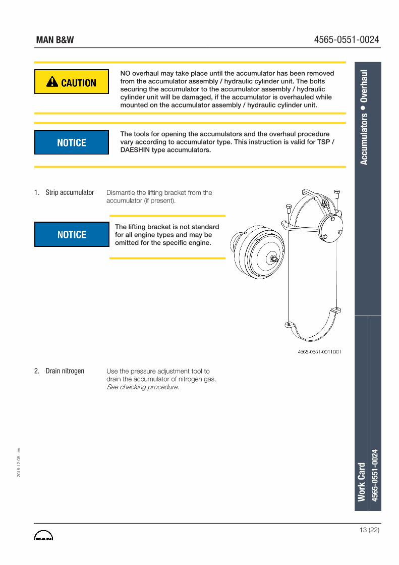
1. Strip accumulator Dismantle the lifting bracket from theaccumulator (if present).
The lifting bracket is not standardfor all engine types and may beomitted for the specific engine.
2. Drain nitrogen Use the pressure adjustment tool todrain the accumulator of nitrogen gas.See checking procedure.
2016
-12-
08 -
en
Wor
k Ca
rdAc
cum
ulat
ors
• Ov
erha
ul45
65-0
551-
0024
MAN B&W 4565-0551-0024
13 (22)
3. Mount the plate onthe accumulator
Mount the plate on the underside of theaccumulator.
The screws used for mounting theplate on the accumulator shouldbe discarded after overhaul of theaccumulator as the screws will becritically stressed during the dis-assembly and re-assembly of theaccumulator.
4. Mount theaccumulator in thetool
The accumulator is fixed by means of aspecially designed plate which grips thebottom of the accumulator. The plate isfixed to the bottom of the pin wrench.The accumulator is then mounted in thepin wrench and held in place by the ring.
5. Securing theaccumulator tool
Make sure that the pin wrench tool issecurely fastened to the engine roomdeck. This can be done by screwing orwelding the flanges of the accumulatortool onto the engine room deck in aconvenient place.
Wor
k Ca
rdAc
cum
ulat
ors
• Ov
erha
ul45
65-0
551-
0024
2016
-12-
08 -
en
4565-0551-0024 MAN B&W
14 (22)
6. Securing the adaptorring
The adaptor ring is equipped with slotsin the upper surface which are grippedby the hook wrench. The lower part ofthe adaptor ring is equipped with somepins which fit into the upper surface ofthe accumulator.
7. Removing the upperpart of theaccumulator
Using the hook wrench unscrew theupper part of the accumulator. Insert apiece of pipe in the holes at the end ofthe wings of the hook wrench to provideleverage. If the upper piece binds, it canbe loosened by tapping (in counter-clockwise direction) a few times with ahammer on the wings of the hookwrench.
Unscrew (in counter-clockwise direction)and remove the locking ring of theaccumulator.
8. Remove olddiaphragm
Remove the upper part with thediaphragm from the acuumulator.
Remove the diaphragm from the upperpart and discard it.
2016
-12-
08 -
en
Wor
k Ca
rdAc
cum
ulat
ors
• Ov
erha
ul45
65-0
551-
0024
MAN B&W 4565-0551-0024
15 (22)
9. Clean theaccumulator
Clean both accumulator halvesthoroughly, especially the threads, andmake sure that the parts are dryafterwards.
10. Assemble theaccumulator
Lubricate the accumulator threads of thelower part and the locking ringwithmolybdenum disulphide grease.
Check that the new diaphragm ismade of the same material as theold one.
Do not lubricate the diaphragm.
Mount the new diaphragm on the upperpart of the accumulator and assemblethe accumulator in reverse sequence tothe dis-assembly.
11. Tighten theaccumulator by hand
Using a mandrel tighten the locking ring(in clockwise direction) by hand until it isflush with the lower part of theaccumulator.
Wor
k Ca
rdAc
cum
ulat
ors
• Ov
erha
ul45
65-0
551-
0024
2016
-12-
08 -
en
4565-0551-0024 MAN B&W
16 (22)
12. Fully tighten theaccumulator
Mount the hook wrench on the upperpart of the accumulator in the same wayas during dis-assembly. Using a hammertighten the locking ring of theaccumulator (in clockwise direction) untilthe scratch marks on the locking ringand the lower part of the accumulatorare aligned.
Remove the accumulator from thetightening tool and remove the platefrom the underside of the accumulator.
13. Mount the liftingbracket
Mount the lifting bracket on theaccumulator (if present).
The lifting bracket is not standardfor all engine types and may beomitted for the specific engine.
2016
-12-
08 -
en
Wor
k Ca
rdAc
cum
ulat
ors
• Ov
erha
ul45
65-0
551-
0024
MAN B&W 4565-0551-0024
17 (22)
Great care must be taken to ensure that the area around the workplaceis clean before and during assembly of the hydraulic system.
Mounting of the accumulator assembly can only be done on a stoppedengine with stopped start-up and booster pumps.
1. Preparations formounting theaccumulator
Check the contact surface on theaccumulator assembly. The contactsurface must be absolutely clean and nopressing-in marks or other damagesmay be found.
Mount new sealing rings on theaccumulator assemby.
Using the accumulator lifting tool lowerthe accumulator on to the accumulatorassembly. Mount the bolts.
Remove the accumulator lifting tool.
Wor
k Ca
rdAc
cum
ulat
ors
• M
ount
ing
4565
-055
1-00
24
2016
-12-
08 -
en
4565-0551-0024 MAN B&W
18 (22)
2. Tighten the boltsTighten the bolts in the sequenceshown.
Each individual bolt is to be tightened tothe specified torque.See data. T45-48.
Always tighten the bolts of bothaccumulators, even if only oneaccumulator has been removedfrom the accumulator assembly.
3. Mount the lifting tool Return the assembly to an uprightposition and mount the lifting tool.
2016
-12-
08 -
en
Wor
k Ca
rdAc
cum
ulat
ors
• M
ount
ing
4565
-055
1-00
24
MAN B&W 4565-0551-0024
19 (22)
4. Inspect the mountingholes
Inspect the mounting holes in the HCUblock.
The threads of the holes should be cleanwith no traces of locktite or other lockingcompounds. If necessary clean thethreads with a thread cutting tap.
Lubricate the threads with a littleMolybdenum Disdulphide.
5. Mount theaccumulatorassembly
Mount new O-rings and sealing ringsbetween the flange and the HCU block.
Using a tackle and/or the engine roomcrane lift the accumulator assembly intoposition next to the HCU block.
Mount the bolts.
Do not use Locktite or otherlocking compounds.
6. Tighten the bolts Tighten the 8 bolts using a torquewrench in the following 3 steps (A-B-C)as shown in data T45-49.
Wor
k Ca
rdAc
cum
ulat
ors
• M
ount
ing
4565
-055
1-00
24
2016
-12-
08 -
en
4565-0551-0024 MAN B&W
20 (22)
7. Remove the liftingtool
Remove the lifting tool and secure thebolts in their place at the tool baseplate.
2016
-12-
08 -
en
Wor
k Ca
rdAc
cum
ulat
ors
• M
ount
ing
4565
-055
1-00
24
MAN B&W 4565-0551-0024
21 (22)
8. Re-mount piping Re-mount the piping (if present) betweenthe two accumulators.
Tighten the reducer (in front of the non-return valve) to the torque stated in dataT45-75.
Do NOT overtighten the reducer.
The piping is not standard on allengines.
9. The smallaccumulators
If the small accumulators have also beenoverhauled, they are to be re-mountedsimilarly. These are also to be cross-tightened inthe manner also previously described.
10. Re-setting the valves Close the high pressure outlet valve 421and open the high pressure inlet valve420.
11. Nitrogen pressure Check accumulator nitrogen pressure. See dataT45-45.
This can only be performed on astopped engine and with stopped start-up and booster pumps.
12. Mounting ofaccumulators onhydraulic powersupply unit
The accumulators on the hydraulic highpressure pumps are mounted in thesame way as on the hydraulic cylinderunit. It may, however, not be necessaryto use the lifting tool. This depends onthe size of the engine.See checking procedure.
Wor
k Ca
rdAc
cum
ulat
ors
• M
ount
ing
4565
-055
1-00
24
2016
-12-
08 -
en
4565-0551-0024 MAN B&W
22 (22)
O Stop the Engine
O Shut off starting air supply - At starting air receiver
O Block the main starting valve
O Shut off starting air distributor/distributing system supply
O Shut off control air supply
O Engage turning gear
O Stop lubricating oil supply
O Shut down hydraulic power supply
Data
Ref. Description Value Unit
T45-38 Flange with two accumulators, weight 200 kg
T45-40 Small accumulator, weight 30 kg
T45-41 Large accumulator, weight 60 kg
T45-43 N2 Charging pressure 136 bar at20°
- Accumulator temperature t°C bar
- Check pressure within ± 5 bar.
- Filling pressure must be as stated above
T45-45 Pressure Adjustment Table
- 0° C 124 bar
- 10° C 130 bar
- 20° C 136 bar
- 30° C 142 bar
- 40° C 148 bar
- 50° C 154 bar
- 60° C 160 bar
- 70° C 166 bar
- 80° C 172 bar
- 90° C 178 bar
- 100° C 185 bar
T45-46 assembly off-set 10 - liter accumulator 9 mm
The task-specific tools used in this procedure are shown on the plates at the endof this chapter or in the chapters indicated by the first two digits in the plate num-ber, e.g. 2570-0010 refers to chapter 25, Bearings.