12
EN Operating Instructions Manual Models 20CK13 thru 20CK20 Sleeved Fire Dampers 479365
ENOperating Instructions Manual
Models 20CK13 thru 20CK20
Sleeved Fire
Dampers
479365

PLEASE READ AND SAVE THESE INSTRUCTIONS.
READ CAREFULLY BEFORE ATTEMPTING
TO ASSEMBLE, INSTALL, OPERATE OR MAINTAIN THE
PRODUCT DESCRIBED.
PROTECT YOURSELF AND OTHERS BY OBSERVING ALL
SAFETY INFORMATION. FAILURE TO COMPLY WITH INSTRUCTIONS
COULD RESULT IN PERSONAL INJURY AND/OR PROPERTY
DAMAGE! RETAIN INSTRUCTIONS FOR FUTURE REFERENCE.
PLEASE REFER TO BACK COVER FOR INFORMATION REGARDING
DAYTON’S WARRANTY AND OTHER IMPORTANT INFORMATION.
Model #: ___________________
Serial #: ___________________
Purch. Date: _______________
Form 5S7454 / Printed in USA04632 Version 0 06/2014
© 2014 Dayton Electric Manufacturing Co.All Rights Reserved

1
SAFETY /
SPECIFIC
ATION
SA
SSEMB
LY / IN
STALLATIO
NO
PERATIO
NTR
OU
BLESH
OO
TING
MA
INTEN
AN
CE /
REPA
IRG
ETTING
STAR
TED
BEFORE YOU BEGINModels are intended for installation in accordance with fire damper requirements established by:
NFPA - National Fire Protection Association
BOCA - National Building Codes
ICBO - Uniform Building Codes
SBCCI - Standard Building Codes
CSFM - California State Fire Marshal
Tools Needed:
• Drill
• Level
• Tape Measure
• Screwdriver
• Wrench
• Pop Rivet Gun (Optional)
UNPACKING
Contents:
• Dayton® Sleeved Fire Damper (1)
• Operating Instructions Manual (1)
Inspect:
• After unpacking unit, inspect carefully for any damage that may have occurred during transit. Check for loose, missing or damaged parts. Shipping damage claim must be filed with carrier.
• See General Safety Instructions on page 2, and Cautions and Warnings as shown.
MA
INTE
NA
NC
E /
REP
AIR
TRO
UB
LESH
OO
TIN
GO
PER
ATIO
NA
SSEM
BLY
/ IN
STA
LLAT
ION
GET
TIN
G S
TAR
TED
2
SAFE
TY /
SPEC
IFIC
ATIO
NS
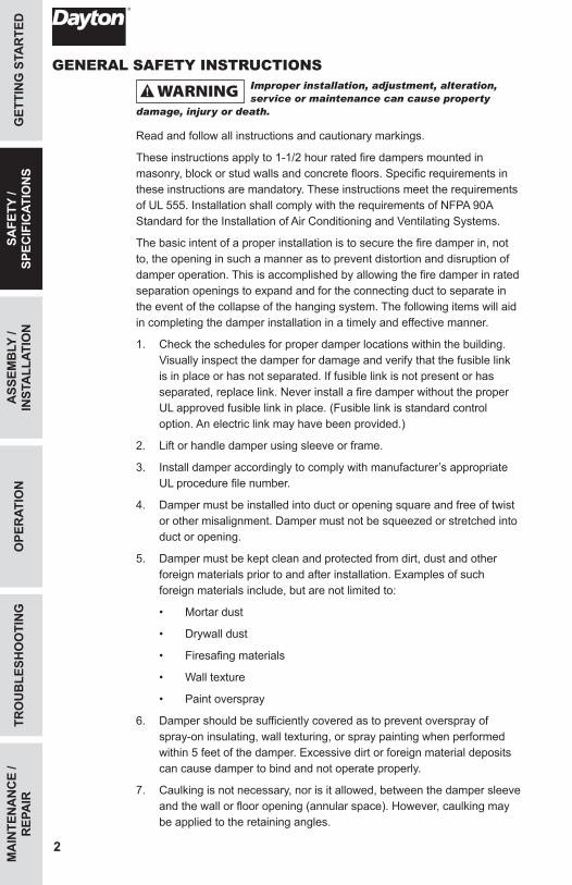
GENERAL SAFETY INSTRUCTIONSImproper installation, adjustment, alteration, service or maintenance can cause property
damage, injury or death.
Read and follow all instructions and cautionary markings.
These instructions apply to 1-1/2 hour rated fire dampers mounted in masonry, block or stud walls and concrete floors. Specific requirements in these instructions are mandatory. These instructions meet the requirements of UL 555. Installation shall comply with the requirements of NFPA 90A Standard for the Installation of Air Conditioning and Ventilating Systems.
The basic intent of a proper installation is to secure the fire damper in, not to, the opening in such a manner as to prevent distortion and disruption of damper operation. This is accomplished by allowing the fire damper in rated separation openings to expand and for the connecting duct to separate in the event of the collapse of the hanging system. The following items will aid in completing the damper installation in a timely and effective manner.
1. Check the schedules for proper damper locations within the building. Visually inspect the damper for damage and verify that the fusible link is in place or has not separated. If fusible link is not present or has separated, replace link. Never install a fire damper without the proper UL approved fusible link in place. (Fusible link is standard control option. An electric link may have been provided.)
2. Lift or handle damper using sleeve or frame.
3. Install damper accordingly to comply with manufacturer’s appropriate UL procedure file number.
4. Damper must be installed into duct or opening square and free of twist or other misalignment. Damper must not be squeezed or stretched into duct or opening.
5. Damper must be kept clean and protected from dirt, dust and other foreign materials prior to and after installation. Examples of such foreign materials include, but are not limited to:
• Mortar dust
• Drywall dust
• Firesafing materials
• Wall texture
• Paint overspray
6. Damper should be sufficiently covered as to prevent overspray of spray-on insulating, wall texturing, or spray painting when performed within 5 feet of the damper. Excessive dirt or foreign material deposits can cause damper to bind and not operate properly.
7. Caulking is not necessary, nor is it allowed, between the damper sleeve and the wall or floor opening (annular space). However, caulking may be applied to the retaining angles.
3
GETTIN
G STA
RTED
ASSEM
BLY /
INSTA
LLATION
OPER
ATION
TRO
UB
LESHO
OTIN
GM
AIN
TENA
NC
E / R
EPAIR
SAFETY /
SPECIFIC
ATION
S
8. ACCESS: Suitable access (such that fusible links can be changed) must be provided for damper inspection and servicing. Where it is not possible to achieve sufficient size access, it will be necessary to install a removable section of duct. (Refer to NFPA 90A).
9. The Code Authority Having Jurisdiction (AHJ) must evaluate and provide approval of final installation where variations to these instructions are necessary.
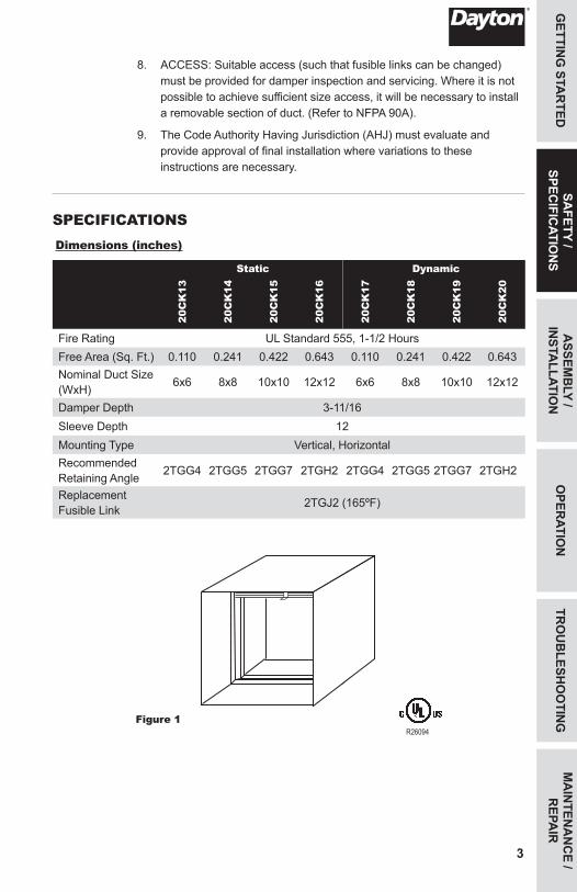
SPECIFICATIONSDimensions (inches)
Static Dynamic
20C
K13
20C
K14
20C
K15
20C
K16
20C
K17
20C
K18
20C
K19
20C
K20
Fire Rating UL Standard 555, 1-1/2 HoursFree Area (Sq. Ft.) 0.110 0.241 0.422 0.643 0.110 0.241 0.422 0.643Nominal Duct Size (WxH) 6x6 8x8 10x10 12x12 6x6 8x8 10x10 12x12
Damper Depth 3-11/16Sleeve Depth 12Mounting Type Vertical, HorizontalRecommended Retaining Angle 2TGG4 2TGG5 2TGG7 2TGH2 2TGG4 2TGG5 2TGG7 2TGH2
Replacement Fusible Link 2TGJ2 (165ºF)
Figure 1R26094

MA
INTE
NA
NC
E /
REP
AIR
TRO
UB
LESH
OO
TIN
GO
PER
ATIO
NSA
FETY
/ SP
ECIF
ICAT
ION
SG
ETTI
NG
STA
RTE
D
4
ASS
EMB
LY /
INST
ALL
ATIO
N
INSTALLATION INSTRUCTIONSNOTE: No additional sleeves are required.
1. Cut wall/floor opening according to the size of your damper allowing the appropriate clearance.
NOTE: Minimum clearance required between the outside of fire damper sleeve assembly and wall/floor opening is 1/8 inch per linear foot of damper width and height with a minimum clearance of 1/4 inch and a maximum of 1-1/2 inches. Equal space around the damper is not required.
2. Prepare your opening between wood/metal studs and sleeve assembly.
a. Frame opening as shown in Figure 2.
Figure 2
12 in.
24". o.c.Maximum
24" o.c.Maximum
(metal studs)
16" o.c.Maximum
(wood studs)
Ceiling Runner24" o.c.Maximum
(metal studs)
Floor Runner16" o.c.Maximum
(wood studs)
2 Panhead Screws
2"
2"
Second set of studs are not required on openings36 in. x 36 in. (914mm x 914mm) or smaller.
Metal Stud Only
FloorRunner
Metal StudFraming Shown
Notched Piece Bent Down
CeilingRunner
24 in.O.C. Max.

5
GETTIN
G STA
RTED
SAFETY /
SPECIFIC
ATION
SO
PERATIO
NTR
OU
BLESH
OO
TING
MA
INTEN
AN
CE /
REPA
IRA
SSEMB
LY / IN
STALLATIO
N
IMPORTANT: All construction and fasteners must meet the requirements of the appropriate wall design (see UL Fire Resistance Directory).
b. Fasten gypsum wall board 12 inches on center to all stud and runner flanges surrounding opening. Refer to Figure 3.
Figure 33. Fire damper assembly must be installed in wall/floor opening using
retaining angles on each side of the wall/floor.
Figure 4
Gypsum Wallboard
Retaining Angle
*Metal Stud or Runner
1"Minimum
Damper Sleeve
*In metal stud construction, exposed steel surfaces need not be covered with gypsum wallboard.
**Wood Stud or Runner
Retaining Angle
**In wood stud construction, gypsum wallboard must cover all wood stud surfaces.
Gypsum Wallboard
Damper Sleeve
1"Minimum
1/4 in. minimum
total clearance
Wall or Floor
Maximum 6 in.
Duct
Damper
Retaining Angle
Maximum 6 in.
Wall or Floor
Retaining Angle
RampDamper
Vertical Mount
Horizontal Mount
Sleeve
Duct
Sleeve
1/4 in. minimum
total clearance
Wall or Floor
Maximum 6 in.
Duct
Damper
Retaining Angle
Maximum 6 in.
Wall or Floor
Retaining Angle
RampDamper
Vertical Mount
Horizontal Mount
Sleeve
Duct
Sleeve
MA
INTE
NA
NC
E /
REP
AIR
TRO
UB
LESH
OO
TIN
GO
PER
ATIO
NSA
FETY
/ SP
ECIF
ICAT
ION
SG
ETTI
NG
STA
RTE
D
6
NOTE: When damper is installed horizontally, the ramp must be positioned up as shown in Figure 4.
a. Retaining angles for 1-1/2 hour rated dampers with a width and height 48 inches or less must be a minimum of 20 ga. The leg of the retaining angle on the damper sleeve shall be a minimum of 1-1/4 inch. The leg of the retaining angle on the wall/floor shall be long enough to cover the annular space and overlap the wall/floor by a minimum of 1 inch.
b. Retaining angles must be attached to the damper using one or more of the following methods of attachment:
• Tack or spot weld
• #10 sheet metal screw
• 1/4 inch bolt and nut
• 3/16 inch steel pop rivet
Attachments must be spaced a maximum of 6 inches on center and a maximum of 2 inches from corners. The angles must be attached to all 4 sides of the sleeve with butt joints at each corner. A minimum of (2) attachments are required on each side, top and bottom. The angles need not be attached to each other at the corners.
Figure 5IMPORTANT: Retaining angles should not be fastened to the wall/floor material. Angles should only sandwich the wall/floor and allow for damper expansion during periods of intense heat.
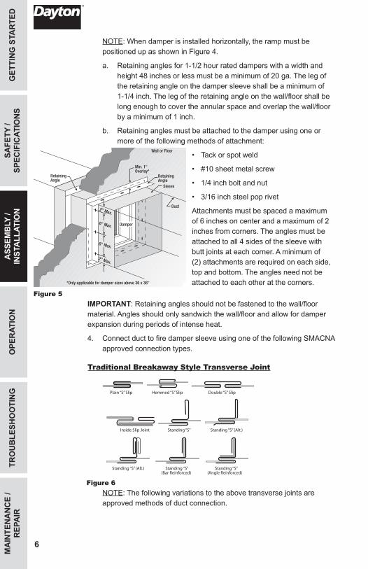
4. Connect duct to fire damper sleeve using one of the following SMACNA approved connection types.
Traditional Breakaway Style Transverse Joint
Figure 6 NOTE: The following variations to the above transverse joints are
approved methods of duct connection.
ASS
EMB
LY /
INST
ALL
ATIO
N
Plain “S” Slip Hemmed “S” Slip Double “S” Slip
Inside Slip Joint Standing “S” Standing “S” (Alt.)
Standing “S” (Alt.) Standing “S” Standing “S” (Bar Reinforced) (Angle Reinforced)
Retaining Angle
Wall or Floor
Min. 1" Overlay*
*Only applicable for damper sizes above 36 x 36"
Duct
Sleeve
RetainingAngle
Damper
2" Max.
2" Max.
6" Max.
6" Max.

7
GETTIN
G STA
RTED
SAFETY /
SPECIFIC
ATION
SO
PERATIO
NTR
OU
BLESH
OO
TING
MA
INTEN
AN
CE /
REPA
IR
a. Apply a maximum of (2) #10 sheet metal screws on each side and on the bottom located in the center of the slip pocket, penetrating both sides of the slip pocket.
b. Apply transverse joints as top and bottom joints with Drive Slip - side joints in duct heights up to 20 inches. See Figure 7.
Manufactured Flanged System Breakaway Connections
1. Install connection system manufactured by Ductmate, Ward or Nexus as illustrated in Figure 8.
Figure 8
Proprietary Flange System Breakaway Connections
1. Install TDC (by Lockformer) or TDF (by Engle) system as described in the SMACNA Duct Construction Standards.
2. Standard 6 inch metal clip may be used with spacing. See Figure 9.
Figure 93. If desired, fasten together corner pieces using 3/8 inch metal bolts and
nuts.
NOTE: All breakaway connections described may have duct sealant applied, PA2084T duct sealant adhesive manufactured by Precision or DP1010 water base duct sealant by Design Polymetrics, in accordance with SMACNA recommendations.
ASSEM
BLY /
INSTA
LLATION
Drive Slip Joint
Figure 7
Fire DamperSleeve
Neoprene GasketBetween all Angles
Flanged System Angles
Attach per Manufacturer’s Instructions
Duct
Do Not BoltCorners
6" long 1/16" maximum thickness plastic cleats;12" c-c per side
DuctSleeve
6 in.
Std. ClipLength
CLDuct
60 in. Duct4 Req’d.
48 in. Duct3 Req’d.
36 in. Duct3 Req’d.
24 in. Duct2 Req’d.
18 in. Duct &Smaller1 Req’d.
Clip Spacing
Typical TDC/TDF Joint
6 in. 6 in.9 in.
7 in.7 in.
5 in. 5 in.
5 in.5 in.

OPE
RAT
ION
ASS
EMB
LY /
INST
ALL
ATIO
NSA
FETY
/ SP
ECIF
ICAT
ION
SG
ETTI
NG
STA
RTE
D
8
MA
INTE
NA
NC
E /
REP
AIR
TRO
UB
LESH
OO
TIN
G
TROUBLESHOOTING GUIDESymptom Possible Cause(s) Corrective Action
Damper does not fully open/close
1. Frame is “racked”, causing blades to bind or jamb
1. Adjust frame such that it is square and plumb
2. Screws in damper linkage 2. Locate screws and remove3. Contaminants on damper 3. Clean with non-oil based solvent
Link separated 1. Heat 1. Replace link
MAINTENANCE1. Dampers shall be maintained, cycled and tested in intervals as stated
in the latest editions of NFPA 90A, 92A and UL 864 unless local codes require more frequent inspections.
2. Dampers do not typically require maintenance as long as they are kept dry and clean. If cleaning is necessary, use mild detergents or solvents. If lubrication is desired, do not use oil-based lubricants or any other lubricants that attract contaminants such as dust.

NOTES
9
GETTIN
G STA
RTED
SAFETY /
SPECIFIC
ATION
SA
SSEMB
LY / IN
STALLATIO
NO
PERATIO
NTR
OU
BLESH
OO
TING
MA
INTEN
AN
CE /
REPA
IR

DAYTON ONE-YEAR LIMITED WARRANTYDAYTON ONE-YEAR LIMITED WARRANTY. All Dayton® product models covered in this manual are warranted by Dayton Electric Mfg. Co. (“Dayton”) to the original user against defects in workmanship or materials under normal use for one year after date of purchase. If the Dayton product is part of a set, only the portion that is defective is subject to this warranty. Any product or part which is determined to be defective in material or workmanship and returned to an authorized service location, as Dayton or Dayton’s designee designates, shipping costs prepaid, will be, as the exclusive remedy, repaired or replaced with a new or reconditioned product or part of equal utility or a full refund given, at Dayton’s or Dayton’s designee’s option, at no charge. For limited warranty claim procedures, see “Warranty Service” below. This warranty is void if there is evidence of misuse, mis-repair, mis-installation, abuse or alteration. This warranty does not cover normal wear and tear of Dayton products or portions of them, or products or portions of them which are consumable in normal use. This limited warranty gives purchasers specific legal rights, and you may also have other rights which vary from jurisdiction to jurisdiction.
WARRANTY DISCLAIMERS AND LIMITATIONS OF LIABILITY RELATING TO ALL CUSTOMERS FOR ALL PRODUCTS
LIMITATION OF LIABILITY. TO THE EXTENT ALLOWABLE UNDER APPLICABLE LAW, DAYTON’S LIABILITY FOR CONSEQUENTIAL AND INCIDENTAL DAMAGES IS EXPRESSLY DISCLAIMED. DAYTON’S LIABILITY IN ALL EVENTS IS LIMITED TO AND SHALL NOT EXCEED THE PURCHASE PRICE PAID.
WARRANTY DISCLAIMER. A DILIGENT EFFORT HAS BEEN MADE TO PROVIDE PRODUCT INFORMATION AND ILLUSTRATE THE PRODUCTS IN THIS LITERATURE ACCURATELY; HOWEVER, SUCH INFORMATION AND ILLUSTRATIONS ARE FOR THE SOLE PURPOSE OF IDENTIFICATION, AND DO NOT EXPRESS OR IMPLY A WARRANTY THAT THE PRODUCTS ARE MERCHANTABLE, OR FIT FOR A PARTICULAR PURPOSE, OR THAT THE PRODUCTS WILL NECESSARILY CONFORM TO THE ILLUSTRATIONS OR DESCRIPTIONS. EXCEPT AS PROVIDED BELOW, NO WARRANTY OR AFFIRMATION OF FACT, EXPRESSED OR IMPLIED, OTHER THAN AS STATED IN THE “LIMITED WARRANTY” ABOVE IS MADE OR AUTHORIZED BY DAYTON.
PRODUCT SUITABILITY. MANY JURISDICTIONS HAVE CODES AND REGULATIONS GOVERNING SALES, CONSTRUCTION, INSTALLATION, AND/OR USE OF PRODUCTS FOR CERTAIN PURPOSES, WHICH MAY VARY FROM THOSE IN NEIGHBORING AREAS. WHILE ATTEMPTS ARE MADE TO ASSURE THAT DAYTON PRODUCTS COMPLY WITH SUCH CODES, DAYTON CANNOT GUARANTEE COMPLIANCE, AND CANNOT BE RESPONSIBLE FOR HOW THE PRODUCT IS INSTALLED OR USED. BEFORE PURCHASE AND USE OF A PRODUCT, REVIEW THE SAFETY/SPECIFICATIONS, AND ALL APPLICABLE NATIONAL AND LOCAL CODES AND REGULATIONS, AND BE SURE THAT THE PRODUCT, INSTALLATION, AND USE WILL COMPLY WITH THEM.
CONSUMERS ONLY. CERTAIN ASPECTS OF DISCLAIMERS ARE NOT APPLICABLE TO CONSUMER PRODUCTS SOLD TO CONSUMERS; (A) SOME JURISDICTIONS DO NOT ALLOW THE EXCLUSION OR LIMITATION OF INCIDENTAL OR CONSEQUENTIAL DAMAGES, SO THE ABOVE LIMITATION OR EXCLUSION MAY NOT APPLY TO YOU; (B) ALSO, SOME JURISDICTIONS DO NOT ALLOW A LIMITATION ON HOW LONG AN IMPLIED WARRANTY LASTS, SO THE ABOVE LIMITATION MAY NOT APPLY TO YOU; AND (C) BY LAW, DURING THE PERIOD OF THIS LIMITED WARRANTY, ANY IMPLIED WARRANTIES OF MERCHANTABILITY OR FITNESS FOR A PARTICULAR PURPOSE APPLICABLE TO CONSUMER PRODUCTS PURCHASED BY CONSUMERS, MAY NOT BE EXCLUDED OR OTHERWISE DISCLAIMED.
THIS LIMITED WARRANTY ONLY APPLIES TO UNITED STATES PURCHASERS FOR DELIVERY IN THE UNITED STATES.
WARRANTY SERVICE
To obtain warranty service if you purchased the covered product directly from W.W. Grainger, Inc. (“Grainger”), (i) write or call or visit the local Grainger branch from which the product was purchased or another Grainger branch near you (see www.grainger.com for a listing of Grainger branches); or (ii) contact Grainger by going to www.grainger.com and clicking on the “Contact Us” link at the top of the page, then clicking on the “Email us” link; or (iii) call Customer Care (toll free) at 1-888-361-8649. To obtain warranty service if you purchased the covered product from another distributor or retailer, (i) go to www.grainger.com for Warranty Service; (ii) write or call or visit a Grainger branch near you; or (iii) call Customer Care (toll free) at 1-888-361-8649. In any case, you will need to provide, to the extent available, the purchase date, the original invoice number, the stock number, a description of the defect, and anything else specified in this Dayton One-Year Limited Warranty. You may be required to send the product in for inspection at your cost. You can follow up on the progress of inspections and corrections in the same ways. Title and risk of loss pass to buyer on delivery to common carrier, so if product was damaged in transit to you, file claim with carrier, not retailer, Grainger or Dayton. For warranty information for purchasers and/or delivery outside the United States, please use the following applicable contact information:
Dayton Electric Mfg. Co., 100 Grainger Parkway, Lake Forest, IL 60045 U.S.A. or call +1-888-361-8649
DM_US 44930530-6.019350.0029


