Page 1
1
Slide 12.1
© The McGraw-Hill Companies, 2007
Object-Oriented and Classical Software
Engineering
Seventh Edition, WCB/McGraw-Hill, 2007
Stephen R. [email protected]
Slide 12.2
© The McGraw-Hill Companies, 2007
CHAPTER 12
OBJECT-ORIENTED ANALYSIS
Page 2
2
Slide 12.3
© The McGraw-Hill Companies, 2007
Overview
The analysis workflowExtracting the entity classesObject-oriented analysis: The elevator problem case studyFunctional modeling: The elevator problem case studyEntity class modeling: The elevator problem case studyDynamic modeling: The elevator problem case studyThe test workflow: Object-oriented analysis
Slide 12.4
© The McGraw-Hill Companies, 2007
Overview (contd)
Extracting the boundary and control classesThe initial functional model: The MSG Foundation case studyThe initial class diagram: The MSG Foundation case studyThe initial dynamic model: The MSG Foundation case studyExtracting the boundary classes: The MSG Foundation case studyExtracting the boundary classes: The MSG Foundation case study
Page 3
3
Slide 12.5
© The McGraw-Hill Companies, 2007
Overview (contd)
Refining the use cases: The MSG Foundation case studyUse-case realization: The MSG Foundation case studyIncrementing the class diagram: The MSG Foundation case studyThe specification document in the Unified ProcessMore on actors and use casesCASE tools for the object-oriented analysis workflowChallenges of the object-oriented analysis workflow
Slide 12.6
© The McGraw-Hill Companies, 2007
Object-Oriented Analysis
OOA is a semiformal analysis technique for the object-oriented paradigm
There are over 60 equivalent techniquesToday, the Unified Process is the only viable alternative
During this workflowThe classes are extracted
RemarkThe Unified Process assumes knowledge of class extraction
Page 4
4
Slide 12.7
© The McGraw-Hill Companies, 2007
12.1 The Analysis Workflow
The analysis workflow has two aimsObtain a deeper understanding of the requirementsDescribe them in a way that will result in a maintainable design and implementation
Slide 12.8
© The McGraw-Hill Companies, 2007
The Analysis Workflow (contd)
There are three types of classes:
Entity classes
Boundary classes
Control classes
Page 5
5
Slide 12.9
© The McGraw-Hill Companies, 2007
The Analysis Workflow (contd)
Entity classModels long-lived information
Examples:Account ClassInvestment Class
Slide 12.10
© The McGraw-Hill Companies, 2007
The Analysis Workflow (contd)
Boundary classModels the interaction between the product and the environmentA boundary class is generally associated with input or output
Examples:Investments Report ClassMortgages Report Class
Page 6
6
Slide 12.11
© The McGraw-Hill Companies, 2007
The Analysis Workflow (contd)
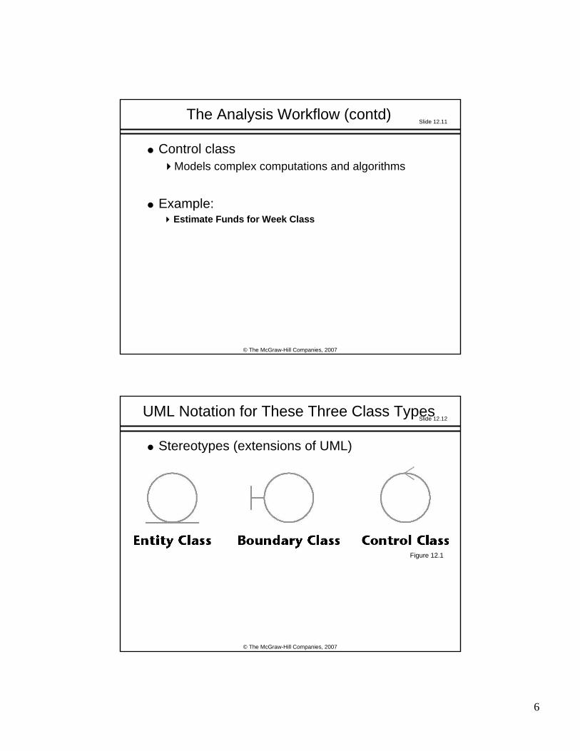
Control classModels complex computations and algorithms
Example:Estimate Funds for Week Class
Slide 12.12
© The McGraw-Hill Companies, 2007
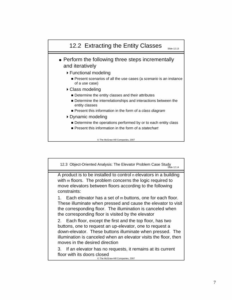
UML Notation for These Three Class Types
Stereotypes (extensions of UML)
Figure 12.1
Page 7
7
Slide 12.13
© The McGraw-Hill Companies, 2007
12.2 Extracting the Entity Classes
Perform the following three steps incrementally and iteratively
Functional modelingPresent scenarios of all the use cases (a scenario is an instance of a use case)
Class modelingDetermine the entity classes and their attributesDetermine the interrelationships and interactions between the entity classesPresent this information in the form of a class diagram
Dynamic modelingDetermine the operations performed by or to each entity classPresent this information in the form of a statechart
Slide 12.14
© The McGraw-Hill Companies, 2007
12.3 Object-Oriented Analysis: The Elevator Problem Case Study
A product is to be installed to control n elevators in a building with m floors. The problem concerns the logic required to move elevators between floors according to the following constraints:1. Each elevator has a set of m buttons, one for each floor. These illuminate when pressed and cause the elevator to visit the corresponding floor. The illumination is canceled when the corresponding floor is visited by the elevator2. Each floor, except the first and the top floor, has two buttons, one to request an up-elevator, one to request a down-elevator. These buttons illuminate when pressed. The illumination is canceled when an elevator visits the floor, thenmoves in the desired direction 3. If an elevator has no requests, it remains at its current floor with its doors closed
Page 8
8
Slide 12.15
© The McGraw-Hill Companies, 2007
12.4 Functional Modeling: The Elevator Problem Case Study
A use case describes the interaction betweenThe product, andThe actors (external users)
Slide 12.16
© The McGraw-Hill Companies, 2007
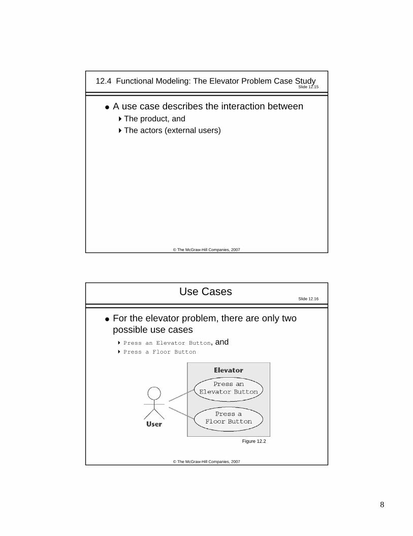
Use Cases
For the elevator problem, there are only two possible use cases
Press an Elevator Button, andPress a Floor Button
Figure 12.2
Page 9
9
Slide 12.17
© The McGraw-Hill Companies, 2007
Scenarios
A use case provides a generic description of the overall functionality
A scenario is an instance of a use case
Sufficient scenarios need to be studied to get a comprehensive insight into the target product being modeled
Slide 12.18
© The McGraw-Hill Companies, 2007
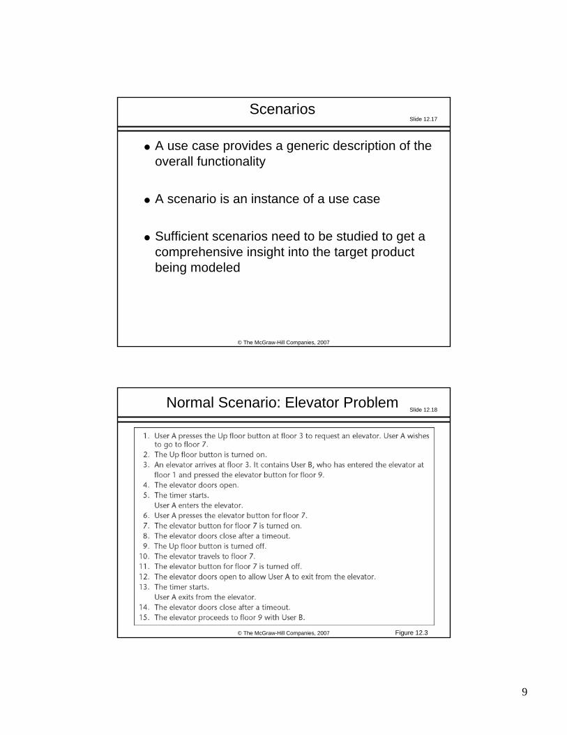
Normal Scenario: Elevator Problem
Figure 12.3
Page 10
10
Slide 12.19
© The McGraw-Hill Companies, 2007
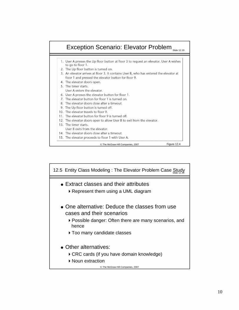
Exception Scenario: Elevator Problem
Figure 12.4
Slide 12.20
© The McGraw-Hill Companies, 2007
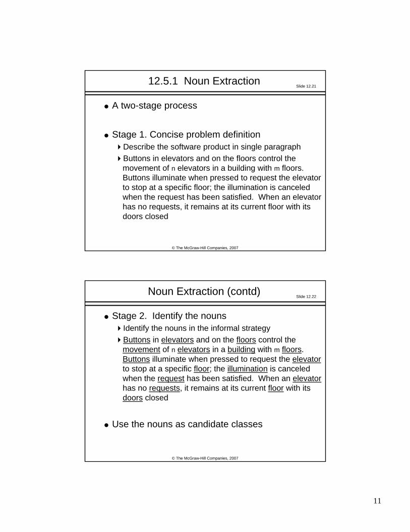
12.5 Entity Class Modeling : The Elevator Problem Case Study
Extract classes and their attributesRepresent them using a UML diagram
One alternative: Deduce the classes from use cases and their scenarios
Possible danger: Often there are many scenarios, and henceToo many candidate classes
Other alternatives: CRC cards (if you have domain knowledge)Noun extraction
Page 11
11
Slide 12.21
© The McGraw-Hill Companies, 2007
12.5.1 Noun Extraction
A two-stage process
Stage 1. Concise problem definitionDescribe the software product in single paragraph Buttons in elevators and on the floors control the movement of n elevators in a building with m floors. Buttons illuminate when pressed to request the elevator to stop at a specific floor; the illumination is canceled when the request has been satisfied. When an elevator has no requests, it remains at its current floor with its doors closed
Slide 12.22
© The McGraw-Hill Companies, 2007
Noun Extraction (contd)
Stage 2. Identify the nounsIdentify the nouns in the informal strategyButtons in elevators and on the floors control the movement of n elevators in a building with m floors. Buttons illuminate when pressed to request the elevatorto stop at a specific floor; the illumination is canceled when the request has been satisfied. When an elevatorhas no requests, it remains at its current floor with its doors closed
Use the nouns as candidate classes
Page 12
12
Slide 12.23
© The McGraw-Hill Companies, 2007
Noun Extraction (contd)
Nounsbutton, elevator, floor, movement, building, illumination, request, door
floor, building, door are outside the problem boundary —excludemovement, illumination, request are abstract nouns —exclude (they may become attributes)
Candidate classes: Elevator Class and Button Class
Subclasses: Elevator Button Class and Floor Button Class
Slide 12.24
© The McGraw-Hill Companies, 2007
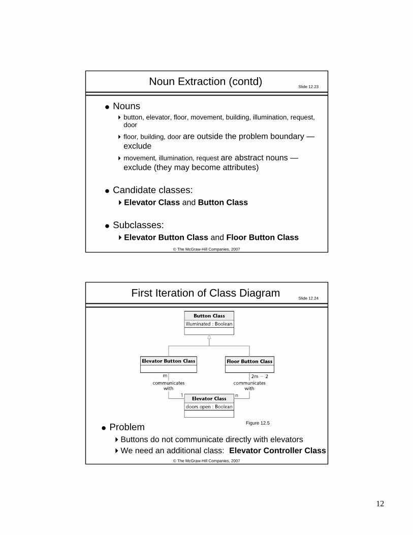
First Iteration of Class Diagram
ProblemButtons do not communicate directly with elevatorsWe need an additional class: Elevator Controller Class
Figure 12.5
Page 13
13
Slide 12.25
© The McGraw-Hill Companies, 2007
Second Iteration of Class Diagram
All relationships are now 1-to-n
This makes design and implementation easier
Figure 12.6
Slide 12.26
© The McGraw-Hill Companies, 2007
12.5.2 CRC Cards
Used since 1989 for OOA
For each class, fill in a card showingName of ClassFunctionality (Responsibility)List of classes it invokes (Collaboration)
Now CRC cards are automated (CASE tool component)
Page 14
14
Slide 12.27
© The McGraw-Hill Companies, 2007
CRC Cards (contd)
StrengthWhen acted out by team members, CRC cards are a powerful tool for highlighting missing or incorrect items
WeaknessIf CRC cards are used to identify entity classes, domain expertise is needed
Slide 12.28
© The McGraw-Hill Companies, 2007
12.6 Dynamic Modeling: The Elevator Problem Case Study
Produce a UML statechart
State, event, and predicate are distributed over the statechart
Figure 12.7
Page 15
15
Slide 12.29
© The McGraw-Hill Companies, 2007
Dynamic Modeling: Elevator Problem (contd)
This UML statechart is equivalent to the state transition diagram of Figures 11.15 through 11.17
This is shown by considering specific scenarios
In fact, a statechart is constructed by modeling the events of the scenarios
Slide 12.30
© The McGraw-Hill Companies, 2007
12.7 The Test Workflow: Object-Oriented Analysis
CRC cards are an excellent testing technique
Figure 12.8
Page 16
16
Slide 12.31
© The McGraw-Hill Companies, 2007
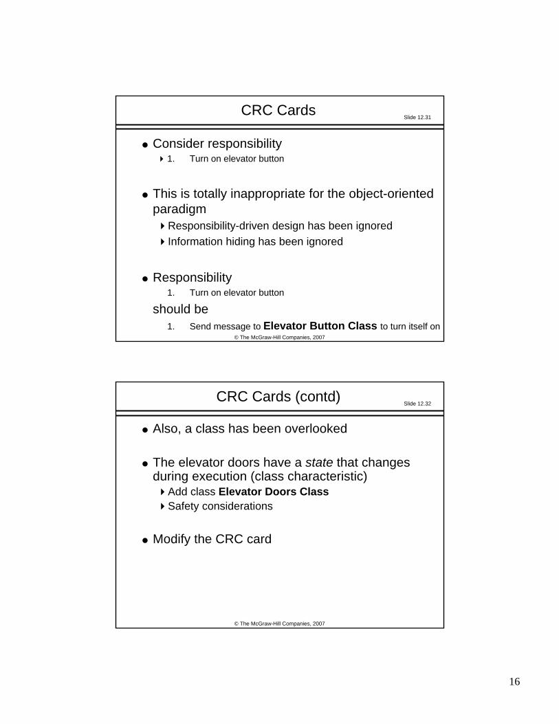
CRC Cards
Consider responsibility1. Turn on elevator button
This is totally inappropriate for the object-oriented paradigm
Responsibility-driven design has been ignoredInformation hiding has been ignored
Responsibility 1. Turn on elevator button
should be1. Send message to Elevator Button Class to turn itself on
Slide 12.32
© The McGraw-Hill Companies, 2007
CRC Cards (contd)
Also, a class has been overlooked
The elevator doors have a state that changes during execution (class characteristic)
Add class Elevator Doors ClassSafety considerations
Modify the CRC card
Page 17
17
Slide 12.33
© The McGraw-Hill Companies, 2007
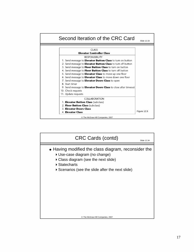
Second Iteration of the CRC Card
Figure 12.9
Slide 12.34
© The McGraw-Hill Companies, 2007
CRC Cards (contd)
Having modified the class diagram, reconsider theUse-case diagram (no change)Class diagram (see the next slide)Statecharts Scenarios (see the slide after the next slide)
Page 18
18
Slide 12.35
© The McGraw-Hill Companies, 2007
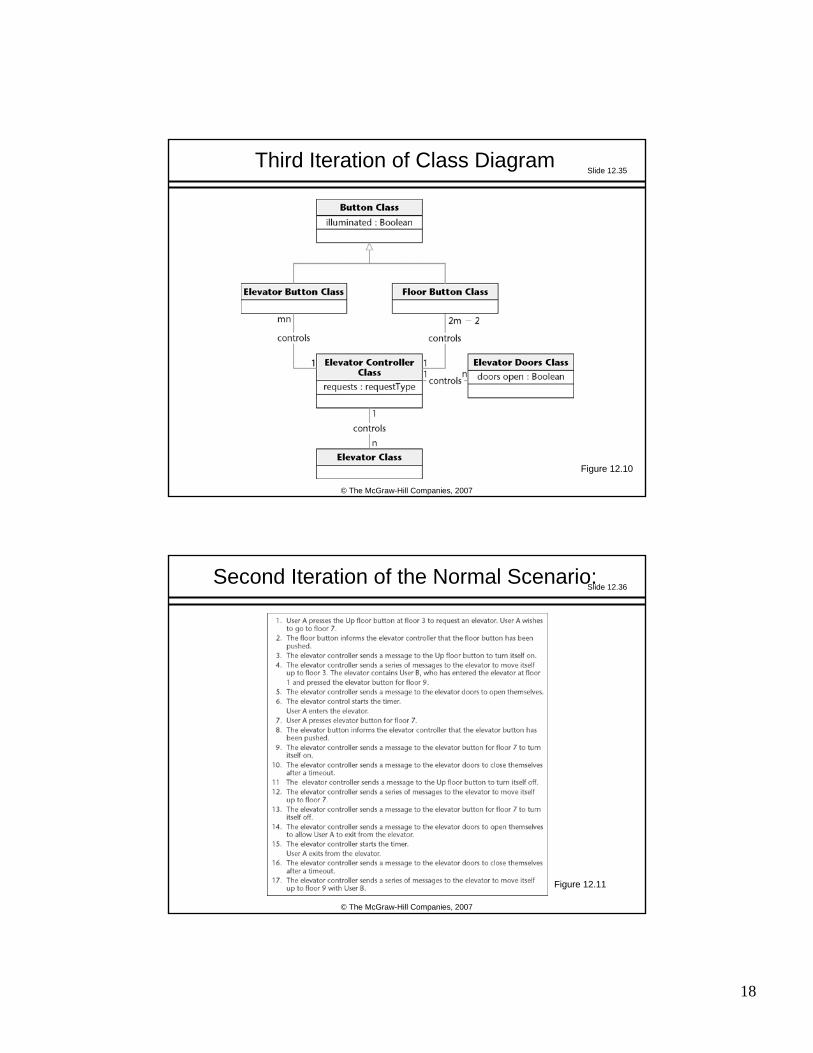
Third Iteration of Class Diagram
Figure 12.10
Slide 12.36
© The McGraw-Hill Companies, 2007
Second Iteration of the Normal Scenario:
Figure 12.11
Page 19
19
Slide 12.37
© The McGraw-Hill Companies, 2007
OOA: Elevator Problem (contd)
The object-oriented analysis is now fine
We should rather say:The object-oriented analysis is fine for now
We may need to return to the object-oriented analysis workflow during the object-oriented design workflow
Slide 12.38
© The McGraw-Hill Companies, 2007
12.8 Extracting the Boundary and Control Classes
EachInput screen, Output screen, and Report
is modeled by its own boundary class
Each nontrivial computation is modeled by a control class
Page 20
20
Slide 12.39
© The McGraw-Hill Companies, 2007
12.9 The Initial Functional Model: MSG Foundation
l Recall the seventh iteration of the use-case diagram
Figure 12.12
Slide 12.40
© The McGraw-Hill Companies, 2007
Use Case Manage a Mortgage
One possible extended scenario
Figure 12.13
Page 21
21
Slide 12.41
© The McGraw-Hill Companies, 2007
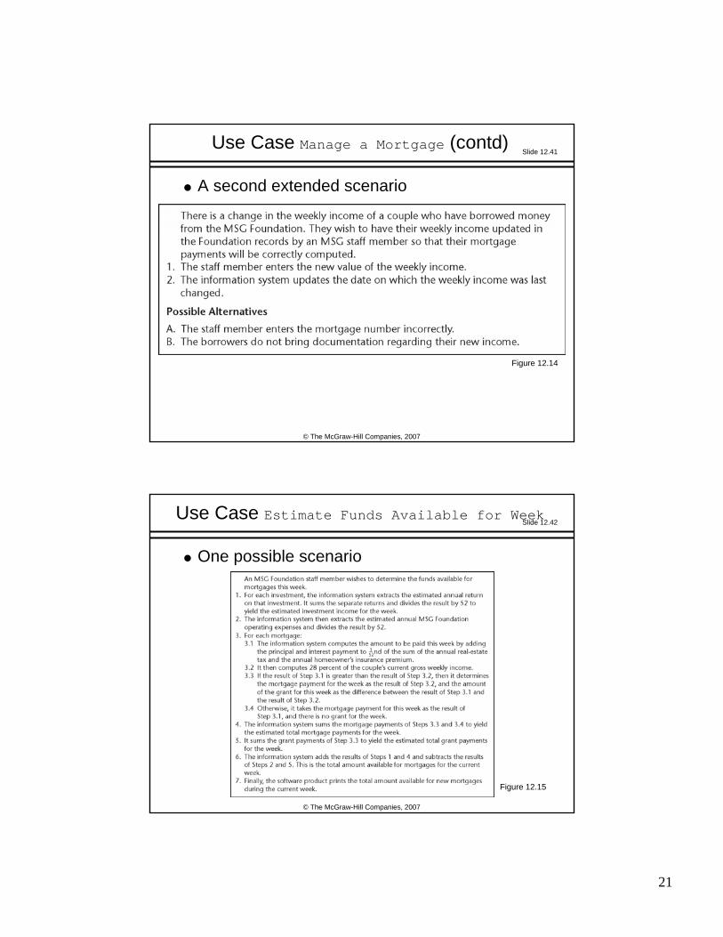
Use Case Manage a Mortgage (contd)
A second extended scenario
Figure 12.14
Slide 12.42
© The McGraw-Hill Companies, 2007
Use Case Estimate Funds Available for Week
One possible scenario
Figure 12.15
Page 22
22
Slide 12.43
© The McGraw-Hill Companies, 2007
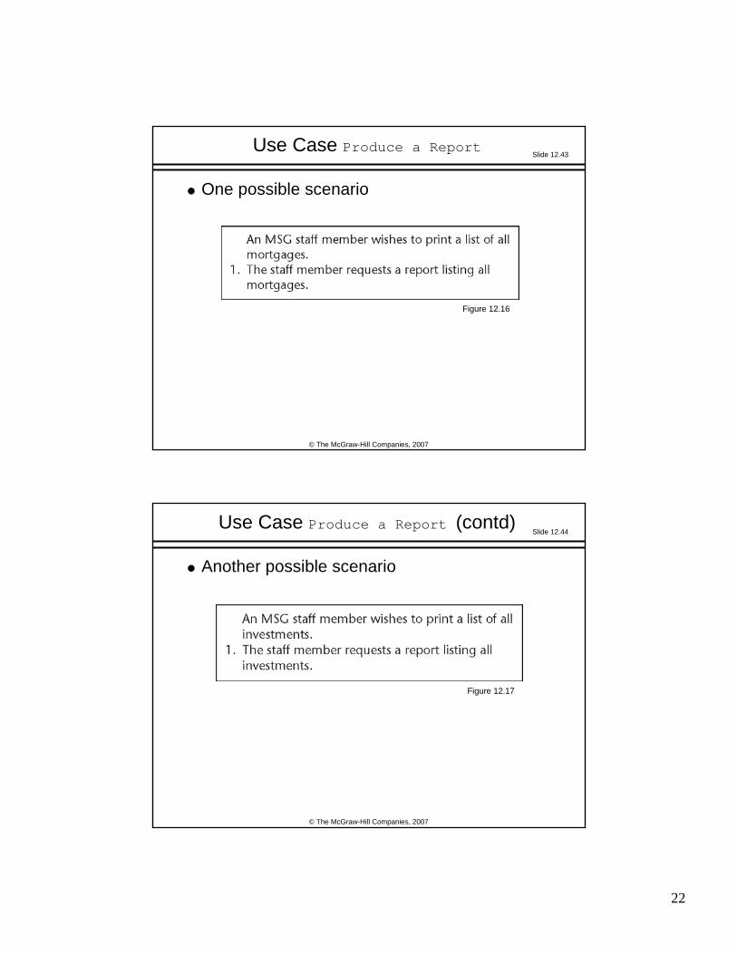
Use Case Produce a Report
One possible scenario
Figure 12.16
Slide 12.44
© The McGraw-Hill Companies, 2007
Use Case Produce a Report (contd)
Another possible scenario
Figure 12.17
Page 23
23
Slide 12.45
© The McGraw-Hill Companies, 2007
12.10 The Initial Class Diagram: MSG Foundation
The aim of entity modeling step is to extract the entity classes, determine their interrelationships, and find their attributes
Usually, the best way to begin this step is to use the two-stage noun extraction method
Slide 12.46
© The McGraw-Hill Companies, 2007
Noun Extraction: MSG Foundation
Stage 1: Describe the information system in a single paragraph
Weekly reports are to be printed showing how much money is available for mortgages. In addition, lists of investments and mortgages must be printed on demand.
Page 24
24
Slide 12.47
© The McGraw-Hill Companies, 2007
Noun Extraction: MSG Foundation (contd)
Stage 2: Identify the nouns in this paragraphWeekly reports are to be printed showing how much money is available for mortgages. In addition, lists of investments and mortgages must be printed on demand.
The nouns are report, money, mortgage, list, and investment
Slide 12.48
© The McGraw-Hill Companies, 2007
Noun Extraction: MSG Foundation (contd)
Nouns report and list are not long lived, so they are unlikely to be entity classes (report will surely turn out to be a boundary class)
money is an abstract noun
This leaves two candidate entity classesMortgage Class and Investment Class
Page 25
25
Slide 12.49
© The McGraw-Hill Companies, 2007
First Iteration of the Initial Class Diagram
Figure 12.18
Slide 12.50
© The McGraw-Hill Companies, 2007
Second Iteration of the Initial Class Diagram
Operations performed on the two entity classes are likely to be very similar
Insertions, deletions, and modifications All members of both entity classes have to be printed on demand
Mortgage Class and Investment Class should be subclasses of a superclass called Asset Class
Page 26
26
Slide 12.51
© The McGraw-Hill Companies, 2007
Second Iteration of Initial Class Diagram (contd)
Figure 12.19
Slide 12.52
© The McGraw-Hill Companies, 2007
Back to the Requirements Workflow
The current five use cases include Manage a Mortgageand Manage an Investment
These two can now be combined into a single use case, Manage an Asset
Page 27
27
Slide 12.53
© The McGraw-Hill Companies, 2007
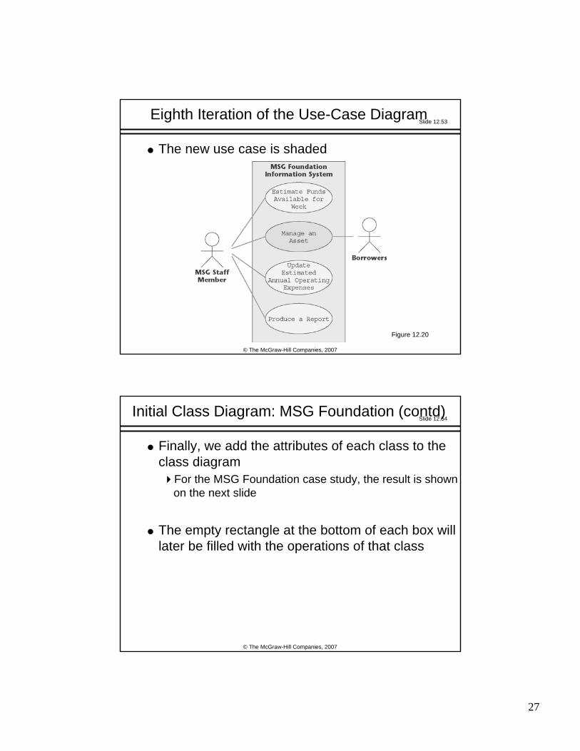
Eighth Iteration of the Use-Case Diagram
The new use case is shaded
Figure 12.20
Slide 12.54
© The McGraw-Hill Companies, 2007
Initial Class Diagram: MSG Foundation (contd)
Finally, we add the attributes of each class to the class diagram
For the MSG Foundation case study, the result is shown on the next slide
The empty rectangle at the bottom of each box will later be filled with the operations of that class
Page 28
28
Slide 12.55
© The McGraw-Hill Companies, 2007
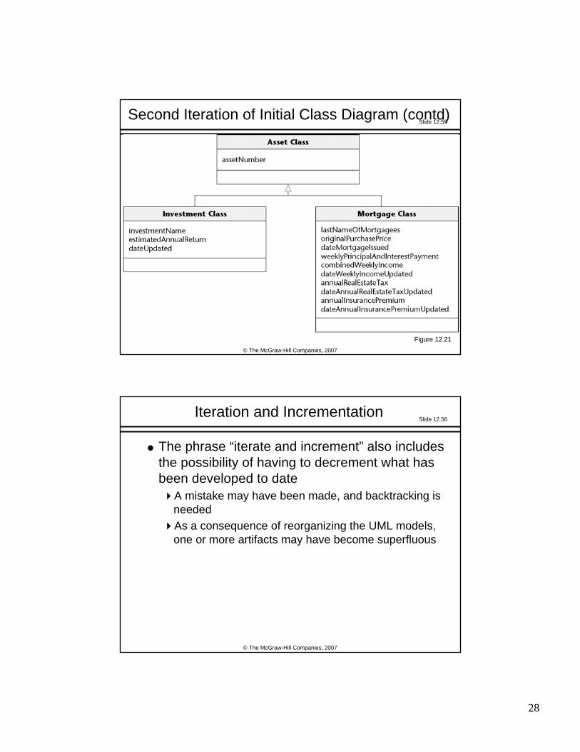
Second Iteration of Initial Class Diagram (contd)
Figure 12.21
Slide 12.56
© The McGraw-Hill Companies, 2007
Iteration and Incrementation
The phrase “iterate and increment” also includes the possibility of having to decrement what has been developed to date
A mistake may have been made, and backtracking is neededAs a consequence of reorganizing the UML models, one or more artifacts may have become superfluous
Page 29
29
Slide 12.57
© The McGraw-Hill Companies, 2007
12.11 The Initial Dynamic Model: MSG Foundation
Dynamic modeling is the third step in extracting the entity classes
A statechart is constructed that reflects all the operations performed by or to the software product
The operations are determined from the scenarios
Slide 12.58
© The McGraw-Hill Companies, 2007
Initial Dynamic Model: MSG Foundation (contd)
Figure 12.22
Page 30
30
Slide 12.59
© The McGraw-Hill Companies, 2007
Initial Dynamic Model: MSG Foundation (contd)
The statechart reflects the operations of the complete MSG Foundation information system
The solid circle on the top left represents the initial state, the starting point of the statechartThe white circle containing the small black circle on the top right represents the final stateStates other than the initial and final states are represented by rectangles with rounded cornersThe arrows represent possible transitions from state to state
Slide 12.60
© The McGraw-Hill Companies, 2007
Initial Dynamic Model: MSG Foundation (contd)
In state MSG Foundation Information System Loop, one of five events can occur
An MSG staff member can issue one of five commands:
estimate funds for the weekmanage an assetupdate estimated annual operating expensesproduce a report, orquit
Page 31
31
Slide 12.61
© The McGraw-Hill Companies, 2007
Initial Dynamic Model: MSG Foundation (contd)
These possibilities are indicated by the five events estimate funds for the week selectedmanage an asset selectedupdate estimated annual operating expenses selectedproduce a report selected, and quit selected
An event causes a transition between states
Slide 12.62
© The McGraw-Hill Companies, 2007
Initial Dynamic Model: MSG Foundation (contd)
An MSG staff member selects an option by clicking on the menu
This graphical user interface (GUI) requires special software
Figure 12.23
Page 32
32
Slide 12.63
© The McGraw-Hill Companies, 2007
Initial Dynamic Model: MSG Foundation (contd)
Equivalent textual user interface that can run on any computer
Figure 12.24
Slide 12.64
© The McGraw-Hill Companies, 2007
12.12 Revising the Entity Classes: MSG Foundation
The initial functional model, the initial class diagram, and the initial dynamic model are completed
Checking them reveals a fault
In the initial statechart, consider state Update Estimated Annual Operating Expenses with operation Update the estimated annual operating expenses
This operation has to be performed on the current value of the estimated annual operating expense
Page 33
33
Slide 12.65
© The McGraw-Hill Companies, 2007
Revising the Entity Classes: MSG Foundation (contd)
But where is the value of the estimated annual operating expenses to be found?
Currently there is only one class (Asset Class) and its two subclasses
Neither is appropriate for storing the estimated annual operating expenses
Slide 12.66
© The McGraw-Hill Companies, 2007
Revising the Entity Classes: MSG Foundation (contd)
The only way a value can be stored on a long-term basis is as an attribute of an instance of that class or its subclasses
Another entity class is needed for storing the estimated annual operating expenses
MSG Application Class
Page 34
34
Slide 12.67
© The McGraw-Hill Companies, 2007
Third Iteration of the Initial Class Diagram: MSG Foundation
MSG Application Classhas other attributes as well
Attributes that do not appertain to the assets
Figure 12.25
Slide 12.68
© The McGraw-Hill Companies, 2007
Third Iteration of the Initial Class Diagram: MSG Foundation
l The class diagram redrawn to show the prototypes
Figure 12.26
Page 35
35
Slide 12.69
© The McGraw-Hill Companies, 2007
12.13 Extracting the Boundary Classes: MSG Foundation
It is usually easy to extract boundary classesEach input screen, output screen, and printed report is generally modeled by a boundary class
One screen should be adequate for all four MSG Foundation use cases
Estimate Funds Available for Week
Manage an Asset
Update Estimated Annual Operating ExpensesProduce a Report
Accordingly there is one initial boundary classUser Interface Class
Slide 12.70
© The McGraw-Hill Companies, 2007
Extracting Boundary Classes: MSG Foundation (contd)
Three reports have to be printedThe estimated funds for the week reportThe listing of all mortgagesThe listing of all investments
Each of these has to be modeled by a separate boundary class
Estimated Funds Report ClassMortgages Report ClassInvestments Report Class
Page 36
36
Slide 12.71
© The McGraw-Hill Companies, 2007
Extracting Boundary Classes: MSG (contd)
Here are the four initial boundary classes
Figure 12.27
Slide 12.72
© The McGraw-Hill Companies, 2007
Initial Boundary Classes: MSG Foundation (contd)
There are three reports: The purchases reportThe sales reportThe future trends report
The content of each report is different Each report therefore has to be modeled by a separate boundary class
Page 37
37
Slide 12.73
© The McGraw-Hill Companies, 2007
12.14 Extracting the Control Classes: MSG Foundation
Each computation is usually modeled by a control class
The MSG Foundation case study has just one Estimate the funds available for the week
There is one initial control class
Figure 12.28
Slide 12.74
© The McGraw-Hill Companies, 2007
The description of class extraction is complete
We now therefore return to the Unified Process
Class Extraction (contd)
Page 38
38
Slide 12.75
© The McGraw-Hill Companies, 2007
12.15 Use-Case Realization: The MSG Foundation Case Study
The process of extending and refining use cases is called use-case realization
Slide 12.76
© The McGraw-Hill Companies, 2007
Use-Case Realization (contd)
The verb “realize” is used at least 3 different ways:Understand (“Harvey slowly began to realize that he was in the wrong classroom”);Receive (“Ingrid will realize a profit of $45,000 on the stock transaction”); andAccomplish (“Janet hopes to realize her dream of starting a computer company”)
In the phrase “realize a use case,” the word “realize” is used in this last sense
Page 39
39
Slide 12.77
© The McGraw-Hill Companies, 2007
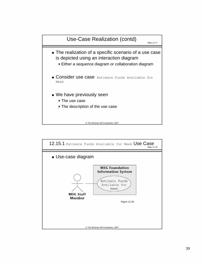
Use-Case Realization (contd)
The realization of a specific scenario of a use case is depicted using an interaction diagram
Either a sequence diagram or collaboration diagram
Consider use case Estimate Funds Available for Week
We have previously seen The use caseThe description of the use case
Slide 12.78
© The McGraw-Hill Companies, 2007
12.15.1 Estimate Funds Available for Week Use Case
Use-case diagram
Figure 12.29
Page 40
40
Slide 12.79
© The McGraw-Hill Companies, 2007
Estimate Funds Available for Week Use Case (contd)
Description of use case
Figure 12.30
Slide 12.80
© The McGraw-Hill Companies, 2007
Estimate Funds Available for Week Use Case (contd)
Class diagram (classes that enter into the use case)
Figure 12.31
Page 41
41
Slide 12.81
© The McGraw-Hill Companies, 2007
Estimate Funds Available for Week Use Case (contd)
The six classes that enter into this use case are: User Interface Class
This class models the user interface
Estimate Funds for Week ClassThis control class models the computation of the estimate of thefunds that are available to fund mortgages during that week
Mortgage Class This class models the estimated grants and payments for the week
Investment ClassThis class models the estimated return on investments for the week
MSG Application ClassThis class models the estimated return on investments for the week
Estimated Funds Report Class This class models the printing of the report
Slide 12.82
© The McGraw-Hill Companies, 2007
Estimate Funds Available for Week Use Case (contd)
Scenario (one possible instance of the use case)
Figure 12.32
Page 42
42
Slide 12.83
© The McGraw-Hill Companies, 2007
Estimate Funds Available for Week Use Case (contd)
A working information system uses objects, not classes
Example: A specific mortgage cannot be represented by Mortgage Class but rather by an object, a specific instance of Mortgage Class
Such an object is denoted by : Mortgage Class
Slide 12.84
© The McGraw-Hill Companies, 2007
Estimate Funds Available for Week Use Case (contd)
A class diagram shows the classes in the use case and their relationships
It does not show the objects nor the sequence of messages as they are sent from object to object
Something more is needed
Page 43
43
Slide 12.85
© The McGraw-Hill Companies, 2007
Estimate Funds Available for Week Use Case (contd)
Collaboration diagram (of the realization of the scenario of the use case)
Figure 12.33
Slide 12.86
© The McGraw-Hill Companies, 2007
Estimate Funds Available for Week Use Case (contd)
The collaboration diagram shows the objects as well as the messages, numbered in the order in which they are sent in the specific scenario
Page 44
44
Slide 12.87
© The McGraw-Hill Companies, 2007
Estimate Funds Available for Week Use Case (contd)
Item 1: The staff member wants to compute the funds available for the weekIn the collaboration diagram, this is modeled by message
1: Request estimate of funds available for week
from MSG Staff Member to : User Interface Class, an instance of User Interface Class
Slide 12.88
© The McGraw-Hill Companies, 2007
Estimate Funds Available for Week Use Case (contd)
Item 2This request is passed on to : Estimate Funds for Week Class, an instance of the control class that actually performs the calculationThis is modeled by message
2: Transfer request
Four separate financial estimates are now determined by : Estimate Funds for Week Class
Page 45
45
Slide 12.89
© The McGraw-Hill Companies, 2007
Estimate Funds Available for Week Use Case (contd)
Item 3In Step 1 of the scenario, the estimated annual return on investments is summed for each investment and the result divided by 52This extraction of the estimated weekly return is modeled by message
3: Request estimated return on investments for week
from : Estimate Funds for Week Class to : Investment Class followed by message
4: Return estimated weekly return on investments
in the other direction
Slide 12.90
© The McGraw-Hill Companies, 2007
Estimate Funds Available for Week Use Case (contd)
Item 4In Step 2 of the scenario, the weekly operating expenses are estimated by taking the estimated annual operating expenses and dividing by 52This extraction of the weekly expenses is modeled by message
5: Request estimated operating expenses for week
from : Estimate Funds for Week Class to : MSG Application Class followed by message
6: Return estimated operating expenses for week
in the other direction
Page 46
46
Slide 12.91
© The McGraw-Hill Companies, 2007
Estimate Funds Available for Week Use Case (contd)
Item 5In Steps 3, 4, and 5 of the scenario, two estimates are determined
the estimated grants for the week, and the estimated payments for the week
This is modeled by message 7: Request estimated grants and payments for week
from : Estimate Funds for Week Class to : Mortgage Class, and by message
8: Return estimated grants and payments for week
in the other direction
Slide 12.92
© The McGraw-Hill Companies, 2007
Estimate Funds Available for Week Use Case (contd)
Item 6Now the arithmetic computation of Step 6 of the scenario is performedThis is modeled by message
9: Compute estimated amount available for week
This is a self call: Estimate Funds for Week Class tells itself to perform the calculationThe result of the computation is stored in : MSG Application Class by message
10: Transfer estimated amount available for week
Page 47
47
Slide 12.93
© The McGraw-Hill Companies, 2007
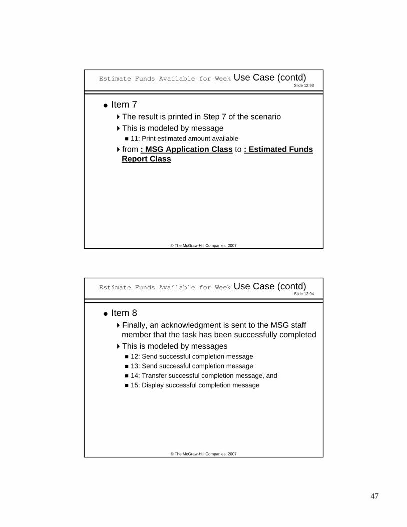
Estimate Funds Available for Week Use Case (contd)
Item 7The result is printed in Step 7 of the scenarioThis is modeled by message
11: Print estimated amount available
from : MSG Application Class to : Estimated Funds Report Class
Slide 12.94
© The McGraw-Hill Companies, 2007
Estimate Funds Available for Week Use Case (contd)
Item 8Finally, an acknowledgment is sent to the MSG staff member that the task has been successfully completedThis is modeled by messages
12: Send successful completion message13: Send successful completion message14: Transfer successful completion message, and 15: Display successful completion message
Page 48
48
Slide 12.95
© The McGraw-Hill Companies, 2007
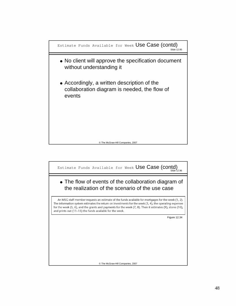
Estimate Funds Available for Week Use Case (contd)
No client will approve the specification document without understanding it
Accordingly, a written description of the collaboration diagram is needed, the flow of events
Slide 12.96
© The McGraw-Hill Companies, 2007
Estimate Funds Available for Week Use Case (contd)
The flow of events of the collaboration diagram of the realization of the scenario of the use case
Figure 12.34
Page 49
49
Slide 12.97
© The McGraw-Hill Companies, 2007
Estimate Funds Available for Week Use Case (contd)
Sequence diagram equivalent to the collaboration diagram (of the realization of the scenario of the use case)
Figure 12.35
Slide 12.98
© The McGraw-Hill Companies, 2007
Interaction Diagrams
The strength of a sequence diagram is that it shows the flow of messages and their order unambiguously
When transfer of information is the focus of attention, a sequence diagram is superior to a collaboration diagram
A collaboration diagram is similar to a class diagram
When the developers are concentrating on the classes, a collaboration diagram is more useful than the equivalent sequence diagram
Page 50
50
Slide 12.99
© The McGraw-Hill Companies, 2007
Estimate Funds Available for Week Use Case (contd)
Figures 12.29 through 12.35 do not depict a random collection of UML artifacts
Instead, these figures depict a use case and artifacts derived from that use case
In more detail (see next slide):
Slide 12.100
© The McGraw-Hill Companies, 2007
Estimate Funds Available for Week Use Case (contd)
Figure 12.29 depicts the use case Estimate Funds Available for Week
The figure models All possible sets of interactionsBetween the actor MSG Staff Member (external to the software product) and the MSG Foundation software product itselfThat relate to the action of estimating funds available for the week
Page 51
51
Slide 12.101
© The McGraw-Hill Companies, 2007
Estimate Funds Available for Week Use Case (contd)
Figure 12.30 is the description of that use case
The figure provides a written account of the details of the Estimate Funds Available for Week use case of Figure 12.29
Slide 12.102
© The McGraw-Hill Companies, 2007
Estimate Funds Available for Week Use Case (contd)
Figure 12.31 is a class diagram showing the classes that realize the Estimate Funds Available for Week use case
The figure depicts The classes that are needed to model all possible scenarios of the use caseTogether with their interactions
Page 52
52
Slide 12.103
© The McGraw-Hill Companies, 2007
Estimate Funds Available for Week Use Case (contd)
Figure 12.32 is a scenario
It depicts one specific instance of the use case of Figure 12.29
Slide 12.104
© The McGraw-Hill Companies, 2007
Estimate Funds Available for Week Use Case (contd)
Figure 12.33 is a collaboration diagram of the realization of the scenario of Figure 12.32
The figure depicts the objects and the messages sent between them in the realization of that one specific scenario
Page 53
53
Slide 12.105
© The McGraw-Hill Companies, 2007
Estimate Funds Available for Week Use Case (contd)
Figure 12.34 is the flow of events of the collaboration diagram of the realization of the scenario of Figure 12.32
Figure 12.34 is a written description of the realization of the scenario of Figure 12.32
(Compare: Figure 12.30 is a written description of the Estimate Funds Available for Week use case of Figure 12.29)
Slide 12.106
© The McGraw-Hill Companies, 2007
Estimate Funds Available for Week Use Case (contd)
Figure 12.35 is the sequence diagram that is fully equivalent to the collaboration diagram of Figure 12.33
The sequence diagram depicts the objects and the messages sent between them in the realization of the scenario of Figure 12.32
Its flow of events is therefore also shown in Figure 12.34
Page 54
54
Slide 12.107
© The McGraw-Hill Companies, 2007
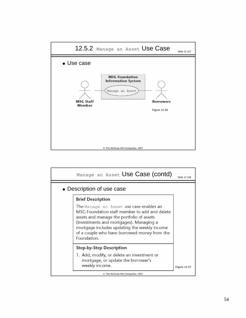
12.5.2 Manage an Asset Use Case
Use case
Figure 12.36
Slide 12.108
© The McGraw-Hill Companies, 2007
Description of use case
Manage an Asset Use Case (contd)
Figure 12.37
Page 55
55
Slide 12.109
© The McGraw-Hill Companies, 2007
Manage an Asset Use Case (contd)
Class diagram showing the classes that realize the use case
Figure 12.38
Slide 12.110
© The McGraw-Hill Companies, 2007
Manage an Asset Use Case (contd)
One scenario of the use case
Figure 12.39
Page 56
56
Slide 12.111
© The McGraw-Hill Companies, 2007
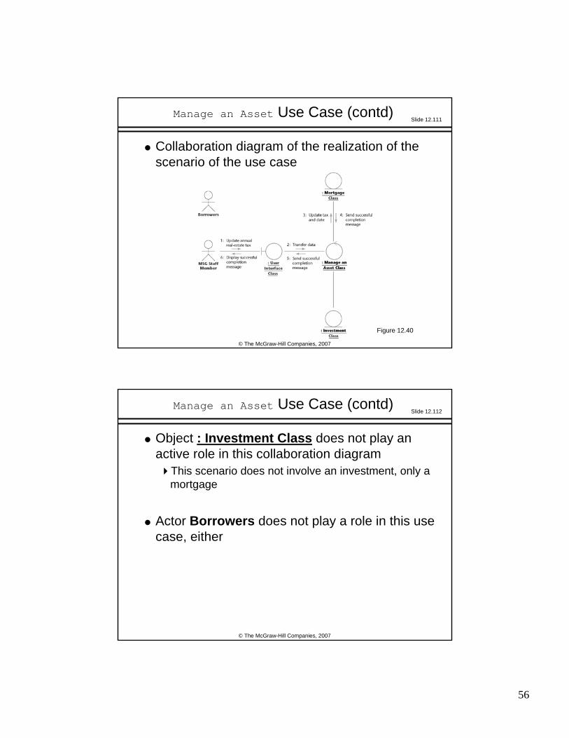
Manage an Asset Use Case (contd)
Collaboration diagram of the realization of the scenario of the use case
Figure 12.40
Slide 12.112
© The McGraw-Hill Companies, 2007
Manage an Asset Use Case (contd)
Object : Investment Class does not play an active role in this collaboration diagram
This scenario does not involve an investment, only a mortgage
Actor Borrowers does not play a role in this use case, either
Page 57
57
Slide 12.113
© The McGraw-Hill Companies, 2007
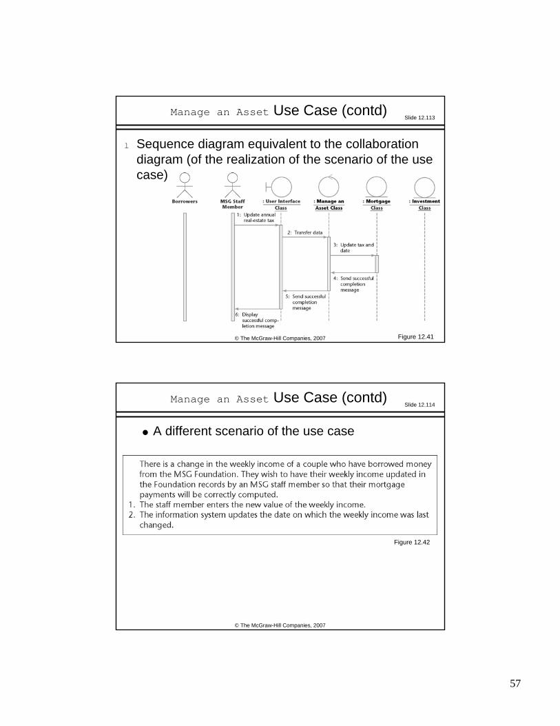
Manage an Asset Use Case (contd)
l Sequence diagram equivalent to the collaboration diagram (of the realization of the scenario of the use case)
Figure 12.41
Slide 12.114
© The McGraw-Hill Companies, 2007
Manage an Asset Use Case (contd)
A different scenario of the use case
Figure 12.42
Page 58
58
Slide 12.115
© The McGraw-Hill Companies, 2007
Manage an Asset Use Case (contd)
Collaboration diagram of the realization of the scenario of the use case
Figure 12.43
Slide 12.116
© The McGraw-Hill Companies, 2007
Manage an Asset Use Case (contd)
At the request of the borrowers, the MSG staff member updates the weekly income of a couple
The scenario is initiated by the Borrowers
Their data are entered into the software product by the MSG Staff Member
This is stated in the note in the collaboration diagram
Page 59
59
Slide 12.117
© The McGraw-Hill Companies, 2007
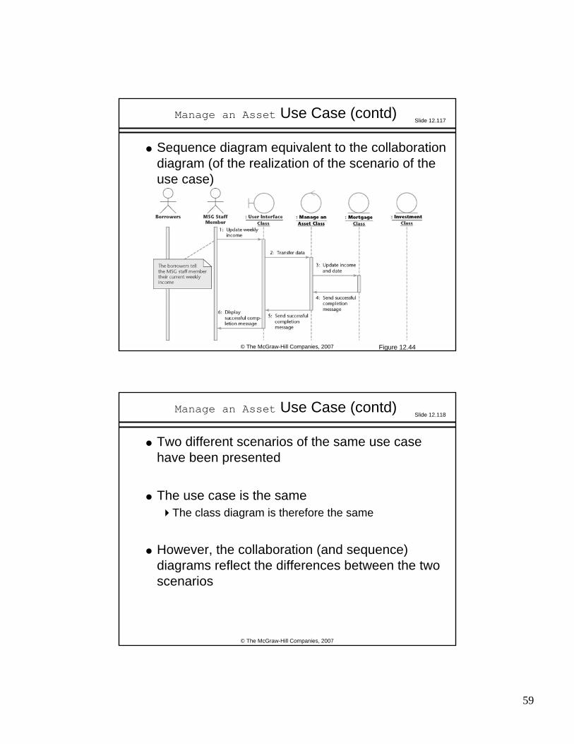
Manage an Asset Use Case (contd)
Sequence diagram equivalent to the collaboration diagram (of the realization of the scenario of the use case)
Figure 12.44
Slide 12.118
© The McGraw-Hill Companies, 2007
Manage an Asset Use Case (contd)
Two different scenarios of the same use case have been presented
The use case is the sameThe class diagram is therefore the same
However, the collaboration (and sequence) diagrams reflect the differences between the two scenarios
Page 60
60
Slide 12.119
© The McGraw-Hill Companies, 2007
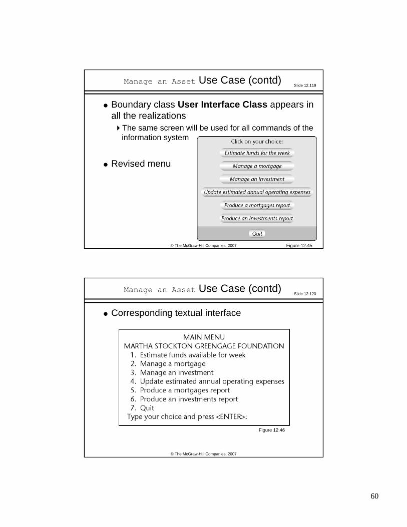
Manage an Asset Use Case (contd)
Boundary class User Interface Class appears in all the realizations
The same screen will be used for all commands of the information system
Revised menu
Figure 12.45
Slide 12.120
© The McGraw-Hill Companies, 2007
Manage an Asset Use Case (contd)
Corresponding textual interface
Figure 12.46
Page 61
61
Slide 12.121
© The McGraw-Hill Companies, 2007
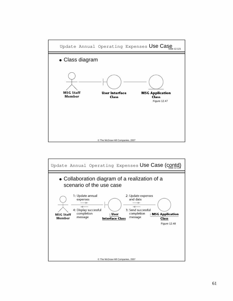
Update Annual Operating Expenses Use Case
Class diagram
Figure 12.47
Slide 12.122
© The McGraw-Hill Companies, 2007
Update Annual Operating Expenses Use Case (contd)
Collaboration diagram of a realization of a scenario of the use case
Figure 12.48
Page 62
62
Slide 12.123
© The McGraw-Hill Companies, 2007
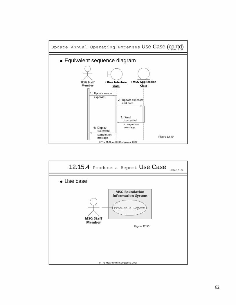
Update Annual Operating Expenses Use Case (contd)
Equivalent sequence diagram
Figure 12.49
Slide 12.124
© The McGraw-Hill Companies, 2007
12.15.4 Produce a Report Use Case
Use case
Figure 12.50
Page 63
63
Slide 12.125
© The McGraw-Hill Companies, 2007
Produce a Report Use Case (contd)
Description of use case
Figure 12.51
Slide 12.126
© The McGraw-Hill Companies, 2007
Produce a Report Use Case (contd)
Class diagram
Figure 12.52
Page 64
64
Slide 12.127
© The McGraw-Hill Companies, 2007
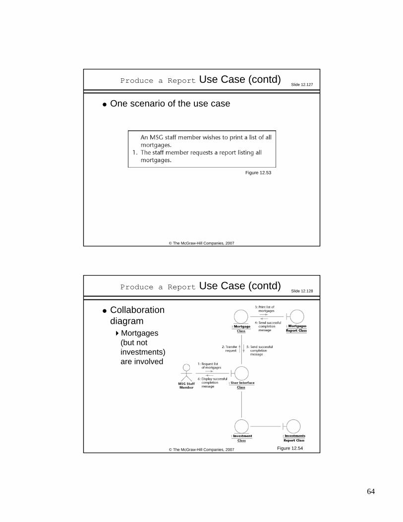
Produce a Report Use Case (contd)
One scenario of the use case
Figure 12.53
Slide 12.128
© The McGraw-Hill Companies, 2007
Produce a Report Use Case (contd)
Collaboration diagram
Mortgages (but not investments) are involved
Figure 12.54
Page 65
65
Slide 12.129
© The McGraw-Hill Companies, 2007
Produce a Report Use Case (contd)
Sequence diagram
Figure 12.55
Slide 12.130
© The McGraw-Hill Companies, 2007
Produce a Report Use Case (contd)
A second scenario (listing all investments) of the use case
Figure 12.56
Page 66
66
Slide 12.131
© The McGraw-Hill Companies, 2007
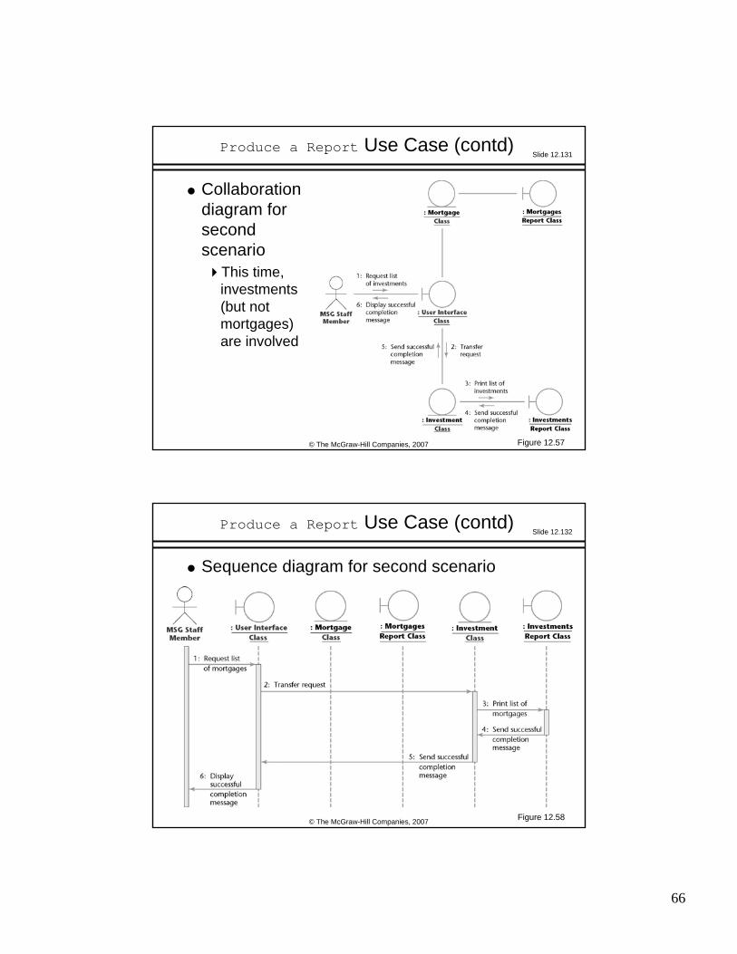
Produce a Report Use Case (contd)
Collaboration diagram for second scenario
This time, investments (but not mortgages) are involved
Figure 12.57
Slide 12.132
© The McGraw-Hill Companies, 2007
Produce a Report Use Case (contd)
Sequence diagram for second scenario
Figure 12.58
Page 67
67
Slide 12.133
© The McGraw-Hill Companies, 2007
12.16 Incrementing the Class Diagram: The MSG Foundation
In the course of realizing the various use casesInterrelationships between classes become apparent
Accordingly, we now combine the realization class diagrams
Slide 12.134
© The McGraw-Hill Companies, 2007
Combining the Realization Class Diagrams
Figure 12.59
Page 68
68
Slide 12.135
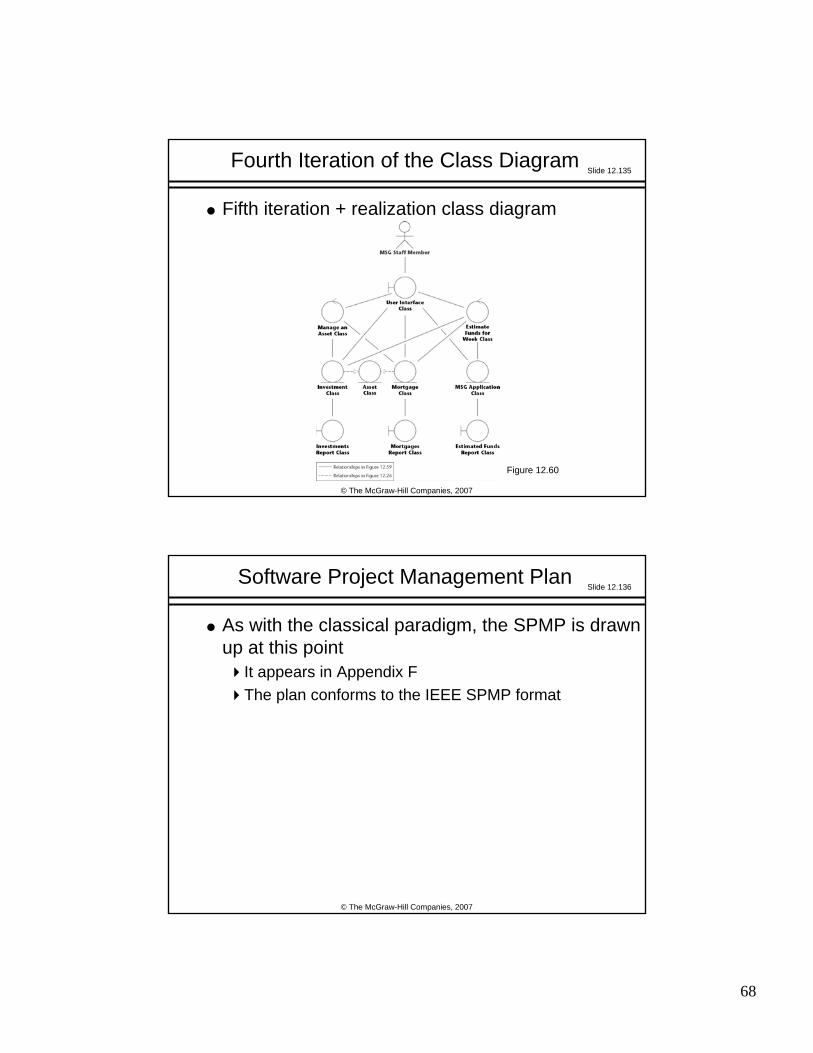
© The McGraw-Hill Companies, 2007
Fifth iteration + realization class diagram
Fourth Iteration of the Class Diagram
Figure 12.60
Slide 12.136
© The McGraw-Hill Companies, 2007
As with the classical paradigm, the SPMP is drawn up at this point
It appears in Appendix FThe plan conforms to the IEEE SPMP format
Software Project Management Plan
Page 69
69
Slide 12.137
© The McGraw-Hill Companies, 2007
CRC cards are used to check the entity classes
All the artifacts are then inspected
12.17 The Test Workflow: MSG Foundation
Slide 12.138
© The McGraw-Hill Companies, 2007
12.18 The Specification Document in the Unified Process
The Unified Process is use-case drivenThe use cases and the artifacts derived from them replace the traditional textual specification document
The client must be shown each use case and associated artifacts, both diagrammatic and textual
These UML diagrams convey to the client more information more accurately than the traditional specification documentThe set of UML diagrams can also play the same contractual role as the traditional specification document
Page 70
70
Slide 12.139
© The McGraw-Hill Companies, 2007
The Specification Document (contd)
A scenario is a specific execution sequence
The client can therefore appreciate how the product works equally well from
A use case together with its scenarios, orA rapid prototype
The difference isThe use cases are successively refined, with more information added each time, whereasThe rapid prototype is discarded
Slide 12.140
© The McGraw-Hill Companies, 2007
The Specification Document (contd)
However, a rapid prototype of the user interface is required
Specimen screens and reports are needed (not a complete rapid prototype)
Page 71
71
Slide 12.141
© The McGraw-Hill Companies, 2007
12.19 More on Actors and Use Cases
To find the actors, consider every role in which an individual can interact with the software product
Example: Applicants, Borrowers
Actors are not individuals They are roles played by those individuals
Find all the different roles played by each userFrom the list of roles, extract the actors
Slide 12.142
© The McGraw-Hill Companies, 2007
More on Actors and Use Cases (contd)
In the Unified ProcessThe term worker is used to denote a role played by an individualIn the Unified Process, Applicants and Borrowers are two different workers
In common parlanceThe word “worker” usually refers to an employee
In this book, the word “role” is used in place of “worker”
Page 72
72
Slide 12.143
© The McGraw-Hill Companies, 2007
More on Actors and Use Cases (contd)
Within a business context, finding the roles is easyThey are displayed within the use-case business model
To find the actorsFind the subset of the use-case business model that corresponds to the use-case model of the requirements
Slide 12.144
© The McGraw-Hill Companies, 2007
More on Actors and Use Cases (contd)
To find the actors (in more detail):Construct the use-case business modelConsider only those parts of the business model that correspond to the proposed software productThe actors in this subset are the actors we seek
Page 73
73
Slide 12.145
© The McGraw-Hill Companies, 2007
More on Actors and Use Cases (contd)
Within a business context, finding use cases is easy
For each role, there will be one or more use casesFind the actors (see previous slide)The use cases then follow
Slide 12.146
© The McGraw-Hill Companies, 2007
12.20 CASE Tools for the Object-Oriented Analysis Workflow
Diagrams play a major role in object-oriented analysis
Diagrams often changeWe need a diagramming toolMany tools go further
All modern tools support UMLCommercial examples
IBM Rational RoseTogether
Open-source exampleArgoUML
Page 74
74
Slide 12.147
© The McGraw-Hill Companies, 2007
12.21 Challenges of the Object-Oriented Analysis Workflow
Do not cross the boundary into object-oriented design
Do not allocate methods to classes yetReallocating methods to classes during stepwise refinement is wasted effort