Sliding-mode and Lyapunov function-based control for battery/supercapacitor hybrid energy storage system used in electric vehicles
Ziyou Song a, b, Jun Hou b, Heath Hofmann b, Jianqiu Li a, c, Minggao Ouyang a, *
a State Key Laboratory of Automotive Safety and Energy, Tsinghua University, Beijing 100084, PR Chinab Department of Electric Engineering and Computer Science, University of Michigan, Ann Arbor, MI 48109, USAc Collaborative Innovation Center of Electric Vehicles in Beijing, Beijing 100081, PR China
a r t i c l e i n f o
Article history:Received 21 November 2016Received in revised form13 January 2017Accepted 19 January 2017Available online 24 January 2017
Keywords:Electric city busHybrid energy storage system (HESS)Sliding-mode controllerLyapunov function-based controllerSupercapacitor
In this paper, the control strategy of a fully-active hybrid energy storage system, which uses two bi-directional DC/DC converters to decouple supercapacitor and battery pack from the DC bus, is pro-posed based on a 5th-order averaged model. Three control objectives, the battery and supercapacitorcurrents as well as the DC bus voltage, are regulated by using the two DC/DC converters. A Lyapunov-function-based controller is proposed to regulate the DC bus voltage to its reference value. In addi-tion, a sliding-mode controller is designed to control the battery and supercapacitor currents to theirreference values. The battery current reference is generated by the energy management strategy, whilethe supercapacitor current reference is generated by the Lyapunov controller to ensure DC bus voltageregulation. Simulation and experimental results show that the proposed control method has satisfactoryperformance, including robust tracking and a smooth transition when the load power varies in the largerange.
Hybrid energy storage systems (HESSs) have become more andmore important in hybrid electric vehicles (HEVs), plug-in hybridelectric vehicles (PHEVs), and all-electric vehicles (EVs) due to thehigh cost of replacing the battery during the life of the vehicle [1].This will be beneficial if the cost of replacing the batteries is greaterthan the cost of the additional supercapacitors (SCs) and associatedinterface electronics [2]. The EV application stresses the batterymore than PHEV and HEV applications because they use a largefraction of the energy stored in the battery [3]. Compared to bat-teries, the SC life is much longer (over one million cycles) and has amuch higher power density. Moreover, the SC can provide fast andeffective energy output because of its high power density and highefficiency [4]. Thus the adoption of SC in the HESS is an effectivesolution to prolong the life span of the battery in EV applications[5].
Regarding the HESS topology, there are three major types:passive, semi-active, and fully active. The passive HESS is the
simplest and lowest-cost topology because the battery and SCpacks are connected in parallel and directly coupled to the DC bus,hence no additional electronic components are needed [6]. How-ever, the performance of this topology is compromised because SCscannot be used effectively. The semi-active HESS, which only em-ploys one DC/DC converter [7], is a good tradeoff between perfor-mance and system cost, therefore it is favored to be used in manyapplications [8]. The fully active HESS employs two DC/DC con-verters and an additional control circuit [9], thus it achieves thebest control effect because both the battery and the SC currents canbe controlled simultaneously [10]. However, this topology demandscompromise in terms of cost and efficiency. In some applications,the DC bus voltage is required to be a constant valuewhich is higherthan both the battery and the SC voltages. The fully active topologyis the only solution in these applications. For this reason, the fullyactive topology shown in Fig. 1 is focused on in this paper.
The key issue with HESS is how to effectively protect the batteryby using the SC. Thus most of the existing literature focuses on theoptimization of the energy management strategy (EMS), whichgenerates reference currents for the battery and the SC. It wasgenerally assumed that a classical reference tracking loop wouldyield a required current from the battery or the SC [11]. The un-derlying control process is commonly neglected. However, there
are complex interactions between the different components withinthe HESS. If the interactions are not taken into consideration, theHESS may not operate as the EMS expects. This means that theproposed EMS cannot work without the help of the underlyingcontrol algorithm, which is also essential to the HESS.
J. S. Prasad et al. used the field programmable gate arraycontrolled DCeDC converter to provide zero voltage and zero cur-rent switching of all the main power devices [12]. A. Mirzaei et al.presented the design and implementation of zero voltage transitionpulse width modulated bidirectional buckeboost converter, andthe calculated efficiency of the suggested converter is more than96% under the full load condition [13]. R. Ling et al. applied asecond-order sliding-mode control approach to buck dc-dc con-verters without requiring current sensing or an integral term in thecontrol loop [14]. M. B. Camara et al. proposed a new SC configu-ration for a semi-active HESS used in HEVs [15]. Based on thisconfiguration, they initialized a polynomial controller to control theSC current [16]. M. Pahlevaninezhad et al. proposed a load adaptivecontroller to charge the battery in EVs [17]. In terms of the fullyactive HESS, which has two degrees of freedom (DOF) in its controlalgorithm, H. Jung et al. derived a 5th-order state-space model torepresent the dynamic response of the HESS [11]. Based on thismodel, they converted the control design problems into numeri-cally efficient optimization problems with linear matrix inequalityconstraints, and finally proposed two state feedback control laws tocontrol the battery current and the DC bus voltage. The gain valuesof the state feedback control can be found to ensure controllerstability. However, the state feedback form is fixed, which may notbe optimal with regard to the control problem.
In this paper, an underlying control algorithm for the fully activeHESS is proposed and analyzed based on the 5th-order averagemodel proposed in Ref. [11]. The target of the proposed controller isto achieve reference tracking for the battery current, the SC current,and the DC bus voltage. The two control inputs are the duty cyclesof the two DC/DC converters. The SC current is also controlledbecause it plays a supporting role to keep the DC bus voltageconstant. To be specific, the battery current reference is generatedby the EMS, while the SC current is generated by a Lyapunovfunction-based controller, which is proposed to regulate the DC busvoltage at its reference value. Moreover, both the battery and the SCcurrents are controlled by the proposed sliding-mode controller.The effectiveness and robustness of the proposed controller, whichincludes the sliding-mode current controller and the Lyapunovfunction-based voltage controller, are validated by simulation andexperimental results. It is also worth noticing that the proposedcontroller can be combined with any existing EMS. The trackingcontrol can be implemented by the proposed controller as long asthe tracking reference is generated by the EMS.
This paper is organized as follows: In Section 2, the state-spaceaveraged model of the HESS is illustrated. Section 3 presents adetailed description of the proposed control method. In Section 4,the proposed controller is implemented on a SimPower modelestablished inMatlab/Simulink. The effectiveness and robustness ofthe proposed controller are also experimentally validated. Thefeasibility of adopting the sliding-mode controller in semi-activeHESS is illustrated in Section 5. Conclusions are presented in Sec-tion 6.
2. The HESS modeling
The circuit diagram of the fully active HESS adopted in this paperis shown in Fig. 2. It consists of a battery pack, a SC pack, twostandard bi-directional DC/DC converters, an inverter, and a motor.It can be assumed that the power demand of the load Pdemand,including the inverter and the motor, can be predicted. It meansthat the load can be represented by a current source with a varyingcurrent im [18]. To simplify the model, only the inner series resis-tance Rbat and RSC of the battery and the SC models are taken intoconsideration. The bi-directional DC/DC converter consists of twoInsulated Gate Bipolar Translators (IGBTs), one capacitor, and oneinductor. The inductor series resistance is considered in the DC/DCmodel. The two IGBTs operate synchronously; for example, when S1is off, S2 is on. Furthermore, S3 and S4 behave similarly. The dutycycle of the IGBT, which varies from 0 to 1, is denoted as Di (i equalsto 1, 2, 3, 4). The on-resistance of switch Si is denoted as Roni. Inaddition, the open-circuit voltages of the battery and the SC aredenoted as Ebat and ESC, respectively.
The average model of the entire HESS during one switchingperiod can be described as
_V1 ¼ � V1
RbatC1� i1C1
þ EbatRbatC1
; (1)
_V2 ¼ � V2
RSCC2� i2C2
þ ESCRSCC2
; (2)
_i1 ¼ V1
L1� i1
RL1 þ Ron2L1
� V0
L1þ D1i1
Ron2 � Ron1L1
þ V0D1
L1; (3)
_i2 ¼ V2
L2� i2
RL2 þ Ron4L2
� V0
L2þ D3i2
Ron4 � Ron3L2
þ V0D3
L2; (4)
_V0 ¼ i1 þ i2C0
� imC0
� D1i1C0
� D3i2C0
; (5)
where V0, V1, and V2 are the voltages corresponding to capacitors C0,C1, and C2; i1 and i2 represent the currents of inductors 1 and 2,respectively. The SC voltage change within one switching period isneglected due to its large capacitance. Based on the average modelshown above, a 5th-order state-space model of the HESS can beobtained. This model was also verified in Ref. [11].
_x ¼ ðA0 þ A1D1 þ A2D3Þxþ Beve; (6)
y ¼ Cx; (7)
where x is the state vector, y is the output vector, and the controlinputs areD1 andD3. To note that, this HESS system is nonlinear dueto the coupling of the inputs (duty ratios of the two DC/DC con-verters) with the states (the battery and the SC currents). To achieve
Fig. 2. The circuit of the fully active HESS.
Z. Song et al. / Energy 122 (2017) 601e612 603
the complete model, the following equations can be defined:
x ¼ ½V1 V2 i1 i2 V0 �;
A11 ¼
26664� 1RbatC1
0
0 � 1RSCC2
37775; A12 ¼
26664� 1C1
0 0
0 � 1C2
0
37775;
A21 ¼
26666664
1L1
0
01L2
0 0
37777775; Be ¼
26666666666664
1RbatC1
0
01
RSCC20 0
0 0
0 0
37777777777775
;
W0 ¼
2666666664
�RL1 þ Ron2L1
0 � 1L1
0 �RL2 þ Ron4L2
� 1L2
1C0
1C0
� imV0C0
3777777775;
W1 ¼
2666664
Ron2 � Ron1L1
01L1
0 0 0
� 1C0
0 0
3777775; W2 ¼
2666664
0 0 0
0Ron4 � Ron3
L2
1L2
0 � 1C0
0
3777775;
A0 ¼�A11 A12A21 W0
�; A1 ¼
�0 00 W1
�; A2 ¼
�0 00 W2
�;
Ve ¼�EbatESC
�; C ¼
�0 0 1 0 00 0 0 1 0
�:
To note that, both A1 and A2 are 5 � 5 matrices, and the 0 ele-ments in A1 and A2 represent all-zero submatrices to satisfy thedimensionality of state-space model. In the averaged model, Ebat
and ESC are assumed to be constant because their changes over aswitching period can be neglected even when the battery and theSC are charged/discharged at high currents. It should be noted thatthis averaged model is only used for the controller design. In thesimulation process, a more detailed Simpower model will beadopted to verify the proposed controller to ensure itseffectiveness.
3. Description of the control design process
Based on the 5th-order state-space model of the HESS, thecontrol algorithm is designed in this section. The rule-based EMSadopted in this paper is also introduced.
3.1. Energy management strategy
Before designing the underlying control algorithm, the EMSwhich splits the power between the battery and the SC should bedetermined according to the load power Pdemand. The batteryreference current ibat,ref can therefore be generated.
The EMS of the HESS has been proven crucial for saving energy,reducing cost, reaching high overall efficiency, and enhancingsystem dynamics [19]. For optimal energymanagement, a variety ofEMSs have been designed and discussed in the existing literature,such as the “all or nothing” control strategy [20], the rule-basedstrategy (RBS) [2], the filtration based strategy (FBS) [21], themodel predictive strategy (MPS) [10], and the fuzzy logic strategy(FLS) [8]. H. Yu et al. formulated a multi-objective optimizationproblem taking into account cycle life of the battery, total energyconsumption and specific requirement that minimizing the use ofbattery [22]. In Ref. [8], RBS, FBS, MPS, and FLS are compared basedon a dynamic battery degradation model. It was shown that the FLSand RBS achieve the best performance among the four strategies[8]. Furthermore, about 50% of the HESS life cycle cost is reduced incomparison with the battery-only configuration along the typicalChina bus driving cycle [8]. The RBS was also verified to be near-optimal using the dynamic programing (DP) approach, as the RBScan preserve most of the characteristics of the DP result [23].
The RBS, as shown in Fig. 3, is therefore adopted in this paper togenerate the battery current reference based on the load powerdemand and the SC voltage. To be specific, under the tractioncondition (Pdemand � 0), the SC does not support any power to loadwhen Pdemand is less than a definite threshold Pmin. When Pdemandexceeds Pmin, the battery tends to output a constant power Pmin and
Fig. 3. The flow-chart of the rule-based strategy.
Fig. 4. Hysteresis controller for the SC high/low voltage protection.
Z. Song et al. / Energy 122 (2017) 601e612604
the SC tends to support the rest of the power demand (Pdemand-Pmin). Under the regenerative condition (Pdemand < 0), the SC tendsto absorb all regenerative energy until it is fully charged to avoidfrequent charge operations on the battery. Actually, all rules areextracted from the DP result and the rule-based strategy used inthis paper can operate in the optimal manner when compared tothe DP results [8]. The SC SOC can be calculated by dividing itsvoltage by its maximum voltage. The SC SOC is strictly controlledabove 0.5 because the efficiency of power conversion becomes poorwhen the SC voltage is low. In addition, 75% of the energy stored inSCs is released when its SOC drops to 0.5. The battery SOC iscontrolled in its recommended SOC usagewindow (from 0.2 to 0.9).
The SC voltage is strictly controlled between 0.5VSC,max andVSC,max (VSC,max is the maximum value of the SC voltage), as the SCefficiency is extremely low in the low voltage range. Thus thebattery is set to charge the SC with a constant value Pch when VSC isless than 0.5VSC,max. A hysteresis control algorithm is included in allthe following controllers to avoid frequent start/stops of the DC/DCconverter. The control scheme is shown in Fig. 4, where the status“1” indicates that the SC is being discharged, the status “0” indicatesthat the SC is idle, and the status “�1” indicates that the SC is beingcharged [8].
3.2. Underlying controller
The tracking problem based on the 5th-order averaged model isnon-linear due to its special form because the control inputs D1 andD3 are multiplied by the system states in the model. In general,there is no definite method for non-linear system control. Withregard to the HESS control, existing methods can be divided intotwo types: the classical control method (frequency domain) and themodern control method (time domain). The core idea of classicalcontrol is to design the controller in the frequency domain based ona linearized system; for example, the polynomial controller pro-posed byM. B. Camara et al. [16]. Themain drawback of the classicalmethod is that non-linear characteristics are neglected, and thecontroller performance may be impaired. In terms of the modern
control method, H. Jung et al. proposed a simple feedback law forthe reference tracking of the DC bus voltage and the battery current[11]. The stability of the control law is ensured by using the LinearMatrix Inequality (LMI) approach to determine the feedback gains.However, the feedback form is fixed in this method, which meansthat the solution is limited.
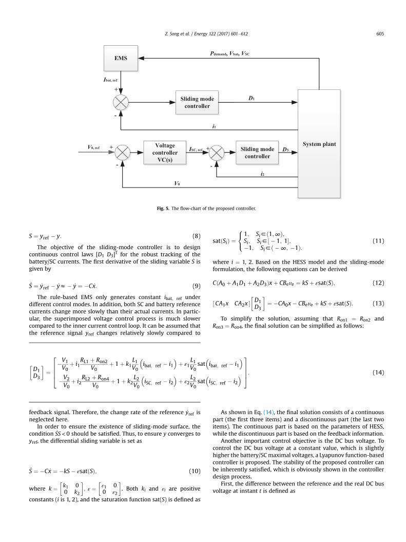
The sliding-mode technique is widely used in non-linearsystem control due to its flexible form and robustness [24]. Forexample, in Ref. [25], a novel fuzzy integral sliding mode currentcontrol strategy is proposed for wind energy system. In Ref. [26],a hybrid controller, which combines the advantages of the inte-graleproportional and the sliding mode controllers, is designedfor a wind-driven induction generator system. The sliding-modecontroller is therefore adopted in this paper to control the bat-tery/SC currents. As Fig. 5 shows, the battery current reference isgenerated by the EMS illustrated above, while the SC currentreference is generated by the Lyapunov function-basedcontroller, which is proposed in this paper to control the DCbus voltage. To be specific, the battery current is controlled tominimize battery degradation, and the SC current is controlled tocompensate the load power demand as well as keep the DC busvoltage constant.
As Eq. (8) shows, the error between the measured and thedesired battery/SC currents are selected to be the sliding variable S
Fig. 5. The flow-chart of the proposed controller.
Z. Song et al. / Energy 122 (2017) 601e612 605
S ¼ yref � y: (8)
The objective of the sliding-mode controller is to designcontinuous control laws [D1 D3]T for the robust tracking of thebattery/SC currents. The first derivative of the sliding variable _S isgiven by
_S ¼ _yref � _yz� _y ¼ �C _x: (9)
The rule-based EMS only generates constant ibat, ref underdifferent control modes. In addition, both SC and battery referencecurrents change more slowly than their actual currents. In partic-ular, the superimposed voltage control process is much slowercompared to the inner current control loop. It can be assumed thatthe reference signal yref changes relatively slowly compared to
�D1D3
�¼
26664�V1
V0þ i1
RL1 þ Ron2V0
þ 1þ k1L1V0
�ibat; ref � i1
�þ ε1
L1V0
sat�ibat; ref � i1
�
�V2
V0þ i2
RL2 þ Ron4V0
þ 1þ k2L2V0
�iSC; ref � i2
�þ ε2
L2V0
sat�iSC; ref � i2
�
37775: (14)
feedback signal. Therefore, the change rate of the reference _yref isneglected here.
In order to ensure the existence of sliding-mode surface, thecondition _SS<0 should be satisfied. Thus, to ensure y converges toyref, the differential sliding variable is set as
_S ¼ �C _x ¼ �kS� εsatðSÞ; (10)
where k ¼�k1 00 k2
�; ε ¼
�ε1 00 ε2
�. Both ki and εi are positive
constants (i is 1, 2), and the saturation function sat(S) is defined as
satðSiÞ ¼8<:
1; Si2ð1;∞Þ;Si; Si2½ � 1; 1�;�1; Si2ð �∞; �1Þ:
(11)
where i ¼ 1, 2. Based on the HESS model and the sliding-modeformulation, the following equations can be derived
CðA0 þ A1D1 þ A2D3Þxþ CBeve ¼ kSþ εsatðSÞ; (12)
½CA1x CA2x ��D1D3
�¼ �CA0x� CBeve þ kSþ εsatðSÞ: (13)
To simplify the solution, assuming that Ron1 ¼ Ron2 andRon3 ¼ Ron4, the final solution can be simplified as follows:
As shown in Eq. (14), the final solution consists of a continuouspart (the first three items) and a discontinuous part (the last twoitems). The continuous part is based on the parameters of HESS,while the discontinuous part is based on the feedback information.
Another important control objective is the DC bus voltage. Tocontrol the DC bus voltage at a constant value, which is slightlyhigher the battery/SCmaximal voltages, a Lyapunov function-basedcontroller is proposed. The stability of the proposed controller canbe inherently satisfied, which is obviously shown in the controllerdesign process.
First, the difference between the reference and the real DC busvoltage at instant t is defined as
Fig. 6. The HESS test-bed.
Z. Song et al. / Energy 122 (2017) 601e612606
eVðtÞ ¼ V0; ref ðtÞ � V0ðtÞ: (15)
The Lyapunov function is set as
VðtÞ ¼ 12C0eVðtÞ2 þ
12KI
0B@
Zt
t0
eVðtÞdt
1CA
2
: (16)
where KI is the integral gain of the DC bus voltage controller, whichwill be shown below. Because the DC bus reference is constant, thedifferential form of the Lyapunov function can be derived as
In the voltage control process, it can be assumed that the bat-tery/SC currents are controlled by the sliding-mode controllerbecause the dynamic of the current controller is much faster thanthat of the voltage controller. In addition, RL1, RL2, Ron2, and Ron4 arevery small, therefore Eq. (14) can be simplified as
�D1ðtÞD3ðtÞ
�z
26664�V1ðtÞV0ðtÞ
þ 1
�V2ðtÞV0ðtÞ
þ 1
37775; (19)
To note that the simplification in Eq. (19) is only adopted in thevoltage control process, the sliding-mode controller (the battery/SCcurrents controller) still uses the control law in Eq. (14). In order tomake the voltage control error converge to 0, the condition _V � 0should be established. Combined with Eqs. (18) and (19), iSC, ref(t)can be chosen as
iSC; ref ðtÞ¼V0ðtÞV2ðtÞ
0B@KPeVðtÞþKI
Zt
t0
eVðtÞdt�V1ðtÞV0ðtÞ
i1ðtÞþ imðtÞ
1CA;
(20)
where KP is the proportional gain, which is positive (KP > 0). Asmentioned above, the current dynamics of the SC can be neglecteddue to its fast response. By integrating Eq. (20) to Eq. (18), thefollowing equation can be therefore derived
_VðtÞ ¼ �KPeVðtÞ2 � 0: (21)
To note that there is no requirement on the KI value, which isgenerally positive (KI > 0), to satisfy the globally stable conditionshown in Eq. (21). As illustrated above, the value of Lyapunovfunction V(t) continuously decreases. In addition, the followingequation can be derived
Z∞
t0
eVðtÞ2dt ¼1KP
ðVð0Þ � Vð∞ÞÞ<∞: (22)
In real applications, the condition presented in Eq. (23) can beensured because the rate of the DC bus voltage is limited by the
current flow through capacitor C0, while the current value is limitedby the inductor.
_eVðtÞ ¼ � _V0ðtÞ ¼ � i0C0
2L∞: (23)
where i0 is the current of capacitor C0. In consequence, the finalconclusion can be derived according to Barbalat's Lemma [27].
limt/∞eVðtÞ ¼ 0: (24)
Thus Lyapunov stability condition can be always satisfied, andthe DC bus voltage converges to its constant reference under allconditions.
4. Simulation and experimental results
In order to verify the effectiveness of the proposed controller, anexperimental system is constructed as shown in Fig. 6. This test-bed, originally presented in Ref. [28], is designed to provide aflexible platform for the experimental validation of different HESStopologies and control algorithms. The DC/DC converters, whichare controlled by a central microprocessor, serve as the actuators tovary the power flow to and from various components of the test-bed. To reduce costs and development time, the test-bed is con-structed largely from the commercially-available hardware. Tosimulate the fully-active HESS adopted in this paper, both batteryand SC packs of the test-bed are connected to the DC bus via DC/DCconverters. The resistive load consists of 20 100U-resistors, whichare connected in parallel. A time-varying load profile can be con-structed by controlling the duty cycle of a DC/DC converter which isused to connect the resistive load and DC bus.
4.1. System controller
To enable rapid prototyping of the advance control algorithms,the test-bed utilizes software and hardware solutions from Math-works® and Speedgoat®. The control algorithm is tested numeri-cally in Matlab/Simulink, and then implemented for experimental
Table 1Manufacturer specifications for system controller.
Pulse-width modulation output 18Quadrature decoding input 2Digital input/output 4Analog-to-digital input 16 in differential modeController area network (CAN) 1Ethernet communication block 1
Table 3Specifications for the SC module.
SC Module
Manufacturer Maxwell Technologies®
Rated Capacitance (F) 63Rated Voltage (V) 125Max. continuous current at 40 �C (A) 240Max. equivalent series resistance (mU) 18
Z. Song et al. / Energy 122 (2017) 601e612 607
validation on the Speedgoat® real-time target by automaticallygenerating C-code from Simulink® controller models. Specificationsfor the Speedgoat® system controller are provided in Table 1. Uti-lizing a single controller for both high- and low-level control cansimplify the development process, and the effect of noise can bereduced, as the switching of the power electronic transistors andthe sampling of the analog-to-digital converters are synchronized.Consequently, the sampling occurs in between switching events,avoiding the pick-up of electromagnetic interference.
4.2. Battery pack
The battery pack consists of 48 LiFePO4 cells which are con-nected in series. The individual cells use bolted interconnectionsvia copper bus bar. The Battery Management System (BMS) fromFlux Power® utilizes a distributed architecture where every BMSmodule manages 4 cells via passive (resistive shunting) cellbalancing. The battery current is measured by the BMS whichcomputes the State-Of-Charge (SOC) of the pack. In addition, cellvoltages and temperatures measured by the BMS are also moni-tored by the BCM via a CAN bus network. In the event of a problem(over/under-voltage cell or over-temperature cell), the BCM willopen contactor relays to prevent damage to the battery pack. Thespecifications of the battery pack are listed in Table 2.
4.3. SC module
The test-bed has four 63F/125V SC modules from MaxwellTechnologies® which can be connected in series/parallel for varioustesting needs. Themodule provides analog feedbackmeasurementsof temperature and voltage. In the test-bed, two SC modules areconnected in series within the SC pack. Manufacturer specificationsfor the SC module are provided in Table 3.
4.4. Simulation results
To verify the effectiveness and robustness of the proposedcontroller, the simulation is carried out in Matlab/Simulink using
Table 2Specifications for the battery pack.
LiFePO4 Battery
Manufacturer Flux Power® (BMS) & Winston® (cells)Voltage limits (V) 2.5/3.9Max. continuous current 3CCapacity (Ah) 100DC voltage (V) 36e144Battery pack resistance (U) 0.08Communication Interface CAN bus
SimPower models, as shown in Fig. 7. The main parameters of theHESS model, which are listed in Table 4, are adopted by measuringthe components of the test-bed. Therefore, the simulation is basedon the real system.
In the simulation process, the load is represented by a currentsource with various current values. The objective of the sliding-mode controller is to design continuous control laws for therobust tracking of the battery/SC currents. The objective of theLyapunov function-based controller is to keep the bus voltage at thedesired value for various load conditions. The DC bus voltagereference is first set to 240V based on the test-bed setup. The initialSOC of the battery is set to 90%, and the initial voltage of the SC isset to 155V. The parameters Pmin and Pch in the rule-based EMS areset to 2kWand 100W, respectively. To validate the robustness of thetracking performance, the load profile includes many step changesand obvious fluctuations, as shown in Fig. 8. A negative Pdemandrepresents the regenerative braking condition, while Pdemand intraction mode ranges from 1 kW to 3.7 kW. From 2s to 4s, a 2-Hzsine wave with the amplitude of 1.5 kW is added to a constantpower to represent the load power ripple, which is a critical testscenario to the proposed controller. In the simulation, the param-eters k1
L1V0, ε1
L1V0, k2
L2V0, and ε2
L2V0
in the sliding-mode controller are setto 5, 0.3, 25, and 2.5 respectively. The parameters KP and KI in theLyapunov function-based controller are 10 and 5.
Fig. 9 shows the simulation result when the bus voltage refer-ence is 240V. The tracking references of V0, ibat, and iSC are plottedwith red curves, and the corresponding tracking results are plottedwith blue curves. The simulation result shows that V0, ibat, and iSCtrack their reference curves accurately and promptly. The responsein the transient region between different power demands issmooth, and there is no obvious overshoot in V0, ibat, and iSC.Especially for V0, the variation is thin and less than 0.5%, which issatisfactory. The smooth transient response means that the averagevalues of V0, ibat, and iSC can track their targets smoothly when thetargets change quickly, even though the chattering components inV0, ibat, and iSC are obvious. Thus the effectiveness of the proposedsliding-mode current controller and the Lyapunov function-basedvoltage controller are verified. In addition, the effectiveness of therule-based EMS is also demonstrated since the SC supplies suffi-cient power to protect the battery and to maintain the desiredoutput demand power.
To validate the robustness of the proposed controller, the HESSparameters are changed in the simulation. Both battery and SCpacks are reduced to half of their original sizes. To be specific, only24 battery cells, connected in series, are used in the battery pack.Furthermore, only one SC module is adopted in the SC pack. Asshown in Fig. 10, the load profile is redesigned for the new simu-lation, and Pmin in the EMS is decreased to 600W accordingly. Theparameters k2
L2V0
and ε2L2V0
are increased to 500 and 30, while theother parameters in the proposed controller remain the same.
The simulation result is shown in Fig. 11, revealing that robusttracking of different variables can be achieved within a large rangeof parameters. Both battery and SC currents can track their desiredvalues accurately when the load switches between light and heavy.The bus voltage is stable during the entire simulation process. The
Fig. 7. The Simpower model used in the simulation.
Table 4Basic parameters of the HESS.
Parameter Value
L1, Battery side inductance (mH) 255RL1, Inductor series resistance at 10 kHz (U) 0.256C1, Battery side filter capacitance (mF) 69L2, Supercapacitor side inductance (mF) 188RSC, SC module resistance (U) 0.011RL2, Inductor series resistance at 10 kHz (U) 0.161C2, Supercapacitor side filter capacitance (mF) 69Ron, MOSFET on-resistance (mU) 21C0, Load side capacitance (mF) 14.85Pulse width module frequency (kHz) 10
Z. Song et al. / Energy 122 (2017) 601e612608
effect of the load fluctuations on the DC bus voltage is mitigated bythe SC. The Lyapunov function-based controller generates SC cur-rent reference fast when the load changes. In the meantime, thesliding-mode controller regulates the SC current accurately.
Fig. 8. Load power demand profile when the bus voltage reference is 240V.
4.5. Comparison of the proposed algorithm with PI controller
To show the advantages of the proposed algorithmwith classicalproportional-integral (PI) controller, simulation is carried out underthe identical condition shown in Fig. 10. The reference of DC busvoltage is still 120V, and the reference of battery current remainsunchanged because the same EMS is used. In the case of classical PIcontrol, both battery/SC currents and DC bus voltage are controlledby well-tuned PI controllers, which are designed according to theinstruction presented in Refs. [15] and [16]. As shown in Fig. 12, thesimulation result shows that both battery/SC currents and DC busvoltage resulting from the proposed algorithm are more interestingthan that of classical PI controller. Compared with PI controller, theproposed algorithm achieves more steady curves of battery/SC
currents and DC bus voltage, which indicates that the proposedalgorithm is more accurate and robust than classical PI controller.
4.6. Experimental results
The experimental test-bed is shown in Fig. 6 and the parametersare listed in Tables 1e4. Regenerative braking conditions cannot bemimicked in the experiments because the resistive load cannotproduce energy as the motor does. Therefore, a new rule, which isthat the battery pack outputs 990W constantly when Pdemand is lessthan 990W, is added in the EMS to allow the battery to charge theSC during the experiment. All parameters of the proposed
Fig. 9. The simulation result when the bus voltage reference is 240V.
Fig. 10. Load power demand profile when the bus voltage reference is 120V.
Fig. 11. The simulation result when the bus voltage reference is 120V.
Z. Song et al. / Energy 122 (2017) 601e612 609
controller remain the same when compared to the simulationprocess on condition that the bus voltage reference is 240V. Asshown in Fig. 13, the load is changed frequently and significantlyduring the experiment.
The objective is to realize the EMS and track the bus voltagereference (240V). As shown in Fig. 14(a), there is no significantchange in V0 during the entire experiment process. Thus the robusttracking performance of V0 is verified. In addition, the experimentresult shows that i1 and i2 (the average values) track their desiredvalues accurately with smooth transition when the load changes.The output voltage and battery/SC currents are always around thedesired reference values. Fig. 14(b) shows that the duty cycles oftwo DC/DC converters corresponding to battery and SC packs haverapid response according to battery and SC current commands,which are generated by the EMS and the Lyapunov function-based
controller, respectively. To note that, the sampling frequency of thecurrent sensor is 10kHz in the experiment, and the current mea-surement is synchronized with the pulse-width modulation(PWM). It means that the battery/SC currents are only measuredonce during one PWM period to obtain their average value. How-ever, in the simulation, the sampling frequency is 100kHz, while thePWM frequency remains 10kHz, meaning that the battery/SC cur-rents are measured ten times during one PWM period. As a result,the current fluctuation components are more evident in simulationresults (as shown in Figs. 9, 11 and 12) than the ones in experimentresults because more dynamic information can be detected in thesimulation.
To further validate the proposed controller, another experimentwith different power range is carried out, as shown in Fig. 15. In thebattery pack, 24 battery cells are connected in series. All parametersof the proposed controller remain the same when compared to thesimulation process on condition that the bus voltage reference is120V. In the EMS, the battery pack is required to output 600Wconstantly when Pdemand is less than 600W. As shown in Fig. 16, thebus voltage and battery/SC currents track their desired referencevalues fast and accurately. Finally, the effectiveness and robustnessof the proposed controller are validated by the experiment. Theproposed controller can therefore be used in practical applications.
5. The application of the sliding-mode controller in semi-active HESS
The control problem of the fully-active HESS, is more complexthan the one related to the semi-active HESS. In terms of the semi-active HESS, the current of SC (or battery) as well as the busvoltage are uncontrollable because only one DC/DC converter isemployed. Thus the bus voltage regulation is not involved in thesemi-active HESS. Actually, the control problem of the semi-activeHESS is included in the one of fully-active HESS (only currentcontrol algorithm is needed in the semi-active HESS). As previ-ously mentioned, the semi-active HESS, which only employs oneDC/DC converter, is the most widely used topology in practicalapplications because it achieves a good tradeoff between
Fig. 12. Comparison result of the proposed algorithm with classical PI controller.
Fig. 13. The load power profile during the experiment.
Fig. 14. The experiment result. (a) The control performance (b) The duty cycle results.
Fig. 15. The load power profile of the new experiment.
Z. Song et al. / Energy 122 (2017) 601e612610
performance and system cost [8]. Therefore the sliding-modecontroller proposed in this paper is validated in a typical semi-active HESS, which is shown in Fig. 17. In the simulation, thebattery pack consists of 48 battery cells, connected in series, andone SC module is adopted in the SC pack. The load profile shownin Fig. 10 is used, and Pmin in EMS is 600W. The parameters k2
L2V0
and ε2L2V0
remain at 500 and 30. To note that, only the sliding-modecontroller is verified, while the Lyapunov function-basedcontroller is not adopted in this section because the bus voltageof the semi-active HESS is uncontrollable.
Fig. 18 is the simulation result of the typical semi-active HESS.Compared to the result of fully-active HESS, the bus voltage of semi-active HESS has slight ripple due to the battery voltage dynamic.The SC current is robustly tracked with smooth transitionwhen theload power switches. Hence, the effectiveness of the proposedsliding-mode controller is verified. As a result, the requirement of
the rule-based EMS is fulfilled.To note that, in some applications of the semi-active HESS, the
Fig. 16. The new experiment result.
Fig. 17. The typical semi-active HESS.
Fig. 18. The simulation result of the semi-active HESS.
Z. Song et al. / Energy 122 (2017) 601e612 611
bus voltage is less than the voltage of the SC (or battery), which isconnected to DC bus via a DC/DC converter. In these cases, the bi-directional DC/DC converter should be reversed. So the expres-sion of the sliding-mode controller should be slightly modifiedaccordingly (reverse V0 and V1/V2, and change the current direc-tion). Due to the space limitation, this content is not explained indetail.
6. Conclusion
In this paper, the control design problem for a fully active bat-tery/SC HESS is addressed. The control objective is to accuratelytrack the reference of battery/SC currents and DC bus voltage dur-ing various load conditions. Based on a 5th-order averagedmodel, asliding-mode current controller and a Lyapunov function-basedvoltage controller are proposed in this paper. The effectivenessand robustness of the proposed controller are verified by simula-tion and experiment. The results show that robust tracking ofdifferent variables can be achieved within a large range of HESSparameters. In addition, the simulation result demonstrates thefeasibility of the proposed sliding-mode controller in semi-active
HESS applications. The proposed controller can be implementedwith any kind of EMS and used in EV/PHEV applications.
Acknowledgement
This research is supported by MoST (Ministry of Science andTechnology of China) under Grand No. 2014DFG71590, and alsosupported by National Key Technology Support Program underGrand No. 2015BAG06B01.
References
[1] Yu HL, Tarsitano D, Hu XS, Cheli F. Real time energy management strategy fora fast charging electric urban bus powered by hybrid energy storage system.Energy 2016:322e31.
[2] Carter R, Cruden A, Hall PJ. Optimizing for efficiency or battery life in a battery/supercapacitor electric vehicle. IEEE Trans Veh Technol 2012;61:1526e33.
[3] Hochgraf CG, Basco JK, Bohn TP, Bloom I. Effect of ultracapacitor-modifiedPHEV protocol on performance degradation in lithium-ion cells. J PowerSources 2014;246:965e9.
[4] Wang Y, Liu C, Pan R, Chen Z. Modeling and state-of-charge prediction oflithium-ion battery and ultracapacitor hybrids with a co-estimator. Energy2017;121:739e50.
[5] Liu H, Wang Z, Cheng J, Maly D. Improvement on the cold cranking capacity ofcommercial vehicle by using supercapacitor and lead-acid battery hybrid. IEEETrans Veh Technol 2009;58:1097e105.
[6] Zheng J, Jow T, Ding M. Hybrid power sources for pulsed current applications.IEEE Trans Aerosp Electron Syst 2001;37:288e92.
[7] Nguyen, Lauber J, Dambrine M. Optimal control based algorithms for energymanagement of automotive power systems with battery/supercapacitorstorage devices. Energy Convers Manag 2014;87:410e20.
[8] Song ZY, Hofmann H, Li JQ, Han XB, Ouyang MG. Energy management stra-tegies comparison for electric vehicles with hybrid energy storage system.Appl Energy 2014;134:321e31.
[9] Pavkovi�c D, Lobrovi�c M, Hrgeti�c M, Komljenovi�c A. A design of cascade controlsystem and adaptive load compensator for battery/ultracapacitor hybrid en-ergy storage-based direct current microgrid. Energy Convers Manag2016;114:154e67.
[10] Hannan MA, Azidin FA, Mohamed A. Multi-sources model and control algo-rithm of an energy management system for light electric vehicles. EnergyConvers Manag 2012;62:123e30.
[11] Jung H, Wang H, Hu T. Control design for robust tracking and smooth tran-sition in power systems with battery/supercapacitor hybrid energy storagedevices. J Power Sources 2014;267:566e75.
[12] Prasad JS, Obulesh YP, Babu CS. FPGA (Field Programmable Gate Array)controlled solar based zero voltage and zero current switching DCeDC
converter for battery storage applications. Energy 2016;106:728e42.[13] Mirzaei, Jusoh A, Salam Z. Design and implementation of high efficiency non-
isolated bidirectional zero voltage transition pulse width modulated DCeDCconverters. Energy 2012;47:358e69.
[14] Ling R, Maksimovic D, Leyva R. Second-order sliding-mode controlled syn-chronous buck DCeDC converter. IEEE Trans Power Electron 2016;31:2539e49.
[15] Camara MB, Gualous H, Gustin F, Berthon A. Design and new control of DC/DCconverters to share energy between supercapacitors and batteries in hybridvehicles. IEEE Trans Veh Technol 2008;57:2721e35.
[16] Camara MB, Gualous H, Gustin F, Berthon A, Dakyo B. DC/DC converter designfor supercapacitor and battery power management in hybrid vehicle appli-cationsdpolynomial control strategy. IEEE Trans Ind Electron 2010;57:587e97.
[17] Pahlevaninezhad M, Drobnik J, Jain PK, Bakhshai A. A load adaptive controlapproach for a zero-voltage-switching DC/DC converter used for electric ve-hicles. IEEE Trans Ind Electron 2012;59:920e33.
[18] Garcia FS, Ferreira AA, Pomilio JA. Control strategy for battery-ultracapacitorhybrid energy storage system. In: IEEE applied power electronics confer-ence and exposition. Washington DC, USA, february 15-19; 2009.
[19] Vinot E, Trigui R. Optimal energy management of HEVs with hybrid storagesystem. Energy Convers Manag 2013;76:437e52.
[20] Allegre L, Bouscayrol A, Trigui R. Influence of control strategies on battery/supercapacitor hybrid energy storage systems for traction applications. In:
IEEE vehicle power and propulsion conference. Michigan, USA, september 7-10; 2009.
[21] Hadartz M, Julander M. Battery-supercapacitor energy storage. Goteborg:University of Chalmers; 2008.
[22] Yu H, Tarsitano D, Hu X, Cheli F. Real time energy management strategy for afast charging electric urban bus powered by hybrid energy storage system.Energy 2016;112:322e31.
[23] Song ZY, Hofmann H, Li JQ, Han XB, Ouyang MG. Integrated optimization for ahybrid energy storage system in electric vehicles using dynamic programingapproach. Appl Energy 2015;139:151e62.
[24] Yuan X, Chen Z, Yuan Y, Huang Y. Design of fuzzy sliding mode controller forhydraulic turbine regulating system via input state feedback linearizationmethod. Energy 2015;93:173e87.
[25] Yin XX, Lin YG, Li W, Gu YJ, Liu HW, Lei PF. A novel fuzzy integral sliding modecurrent control strategy for maximizing wind power extraction and elimi-nating voltage harmonics. Energy 2015;85:677e86.
[26] Lin WM, Hong CM, Cheng FS. On-line designed hybrid controller with adap-tive observer for variable-speed wind generation system. Energy 2010;35:3022e30.
[27] Ioannou PA, Sun J. Robust adaptive control. Courier Dover Publications; 2012.[28] Hou J, Reed DM, Zhou K, Hofmann H, Sun J. Modeling and test-bed develop-
ment for an electric drive system with hybrid energy storage. In: Electricmachines Technology symposium; 2014.