8
IDEC RJ22 Series Slim Power Relays (Bifurcated Contacts)
IDEC RJ22 SeriesSlim Power Relays (Bifurcated Contacts)
2
RJ Series Slim Power Relay Plug-in Terminal (Bifurcated Contacts)
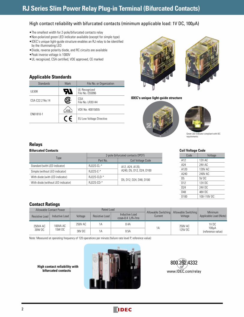
•Thesmallestwidthfor2-pole/bifurcatedcontactsrelay•Non-polarizedgreenLEDindicatoravailable(exceptforsimpletype)•IDEC’suniquelight-guidestructureenablesanRJrelaytobeidentifiedbytheilluminatingLED
•Diode,reversepolaritydiode,andRCcircuitsareavailable•Peakinversevoltageis1000V•ULrecognized,CSAcertified,VDEapproved,CEmarked
Applicable StandardsStandards Mark FileNo.orOrganization
UL508 ULRecognizedFileNo.E55996
CSAC22.2No.14 CSAFileNo.LR35144
EN61810-1VDENo.40015055
EULowVoltageDirective
Light-guide
IDEC's unique light-guide structure
GreenLEDindicatorcompliantwithIECrequirements.
High contact reliability with bifurcated contacts (minimum applicable load: 1V DC, 100µA)
RelaysBifurcated Contacts
Type2-pole(bifurcatedcontactsDPDT)
PartNo. CoilVoltageCode
Standard(withLEDindicator) RJ22S-CL-* A12,A24,A120,A240,D5,D12,D24,D100Simple(withoutLEDindicator) RJ22S-C-*
Withdiode(withLEDindicator) RJ22S-CLD-*D5,D12,D24,D48,D100
Withdiode(withoutLEDindicator) RJ22S-CD-*
Contact RatingsAllowableContactPower RatedLoad
AllowableSwitchingCurrent
AllowableSwitchingVoltage
MinimumApplicableLoad(Note)ResistiveLoad InductiveLoad Voltage ResistiveLoad InductiveLoad
cosø=0.4L/R=7ms
250VAAC30WDC
100VAAC15WDC
250VAC 1A 0.4A1A 250VAC
125VDC
1VDC100μA
(referencevalue)30VDC 1A 0.5A
Note:Measuredatoperatingfrequencyof120operationsperminute(failureratelevelP,referencevalue)
High contact reliability with bifurcated contacts
Coil Voltage CodeCode Voltage
A12 12VACA24 24VACA120 120VACA240 240VACD5 5VDCD12 12VDCD24 24VDCD48 48VDCD100 100-110VDC
800.262.4332www.IDEC.com/relay
3
RJ Series Slim Power Relay Plug-in Terminal (Bifurcated Contacts)
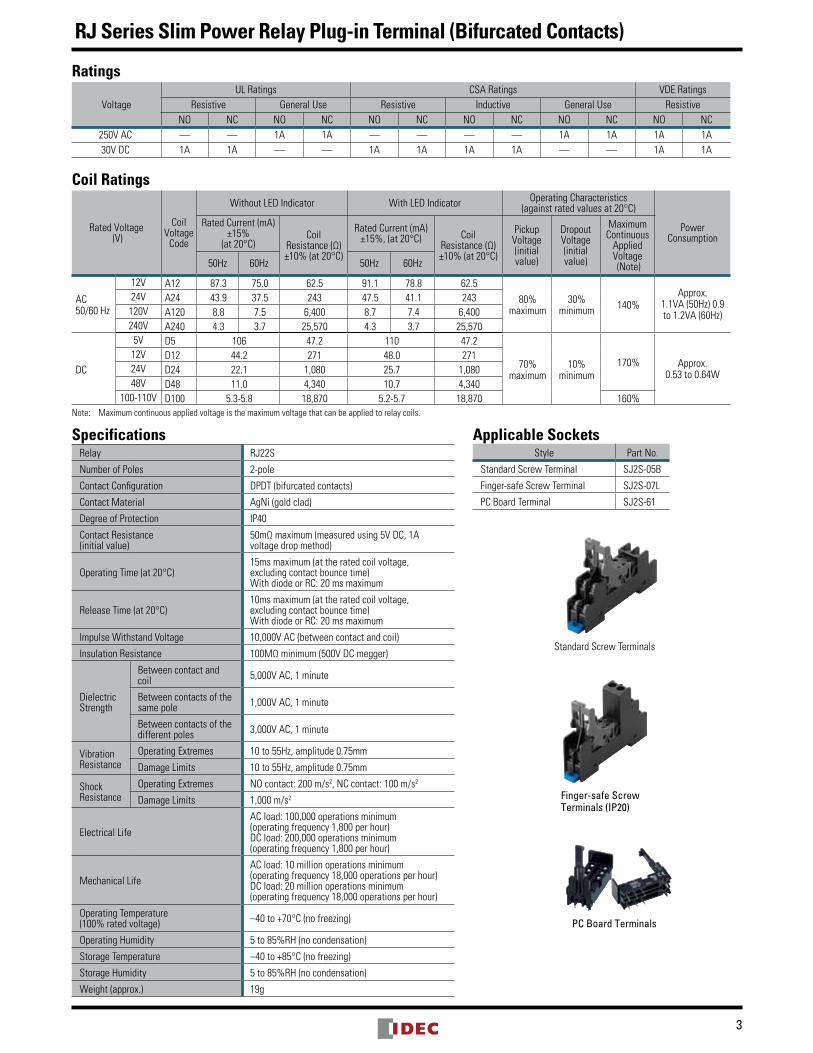
Ratings
VoltageULRatings CSARatings VDERatings
Resistive GeneralUse Resistive Inductive GeneralUse ResistiveNO NC NO NC NO NC NO NC NO NC NO NC
250VAC — — 1A 1A — — — — 1A 1A 1A 1A30VDC 1A 1A — — 1A 1A 1A 1A — — 1A 1A
Coil Ratings
RatedVoltage(V)
CoilVoltageCode
WithoutLEDIndicator WithLEDIndicator OperatingCharacteristics(againstratedvaluesat20°C)
PowerConsumption
RatedCurrent(mA)±15%
(at20°C)Coil
Resistance(Ω)±10%(at20°C)
RatedCurrent(mA)±15%,(at20°C) Coil
Resistance(Ω)±10%(at20°C)
PickupVoltage(initialvalue)
DropoutVoltage(initialvalue)
MaximumContinuousAppliedVoltage(Note)50Hz 60Hz 50Hz 60Hz
AC50/60Hz
12V A12 87.3 75.0 62.5 91.1 78.8 62.580%
maximum30%
minimum 140%Approx.
1.1VA(50Hz)0.9to1.2VA(60Hz)
24V A24 43.9 37.5 243 47.5 41.1 243120V A120 8.8 7.5 6,400 8.7 7.4 6,400240V A240 4.3 3.7 25,570 4.3 3.7 25,570
DC
5V D5 106 47.2 110 47.2
70%maximum
10%minimum
170% Approx.0.53to0.64W
12V D12 44.2 271 48.0 27124V D24 22.1 1,080 25.7 1,08048V D48 11.0 4,340 10.7 4,340
100-110V D100 5.3-5.8 18,870 5.2-5.7 18,870 160%Note: Maximumcontinuousappliedvoltageisthemaximumvoltagethatcanbeappliedtorelaycoils.
SpecificationsRelay RJ22S
NumberofPoles 2-pole
ContactConfiguration DPDT(bifurcatedcontacts)
ContactMaterial AgNi(goldclad)
DegreeofProtection IP40
ContactResistance(initialvalue)
50mΩmaximum(measuredusing5VDC,1Avoltagedropmethod)
OperatingTime(at20°C)15msmaximum(attheratedcoilvoltage,excludingcontactbouncetime)WithdiodeorRC:20msmaximum
ReleaseTime(at20°C)10msmaximum(attheratedcoilvoltage,excludingcontactbouncetime)WithdiodeorRC:20msmaximum
ImpulseWithstandVoltage 10,000VAC(betweencontactandcoil)
InsulationResistance 100MΩminimum(500VDCmegger)
DielectricStrength
Betweencontactandcoil 5,000VAC,1minute
Betweencontactsofthesamepole 1,000VAC,1minute
Betweencontactsofthedifferentpoles 3,000VAC,1minute
VibrationResistance
OperatingExtremes 10to55Hz,amplitude0.75mm
DamageLimits 10to55Hz,amplitude0.75mm
ShockResistance
OperatingExtremes NOcontact:200m/s2,NCcontact:100m/s2
DamageLimits 1,000m/s2
ElectricalLifeACload:100,000operationsminimum(operatingfrequency1,800perhour)DCload:200,000operationsminimum(operatingfrequency1,800perhour)
MechanicalLifeACload:10millionoperationsminimum(operatingfrequency18,000operationsperhour)DCload:20millionoperationsminimum(operatingfrequency18,000operationsperhour)
OperatingTemperature(100%ratedvoltage) –40to+70°C(nofreezing)
OperatingHumidity 5to85%RH(nocondensation)
StorageTemperature –40to+85°C(nofreezing)
StorageHumidity 5to85%RH(nocondensation)
Weight(approx.) 19g
Applicable SocketsStyle PartNo.
StandardScrewTerminal SJ2S-05B
Finger-safeScrewTerminal SJ2S-07L
PCBoardTerminal SJ2S-61
StandardScrewTerminals
Finger-safe Screw Terminals (IP20)
PC Board Terminals
4
RJ Series Slim Power Relay Plug-in Terminal (Bifurcated Contacts)
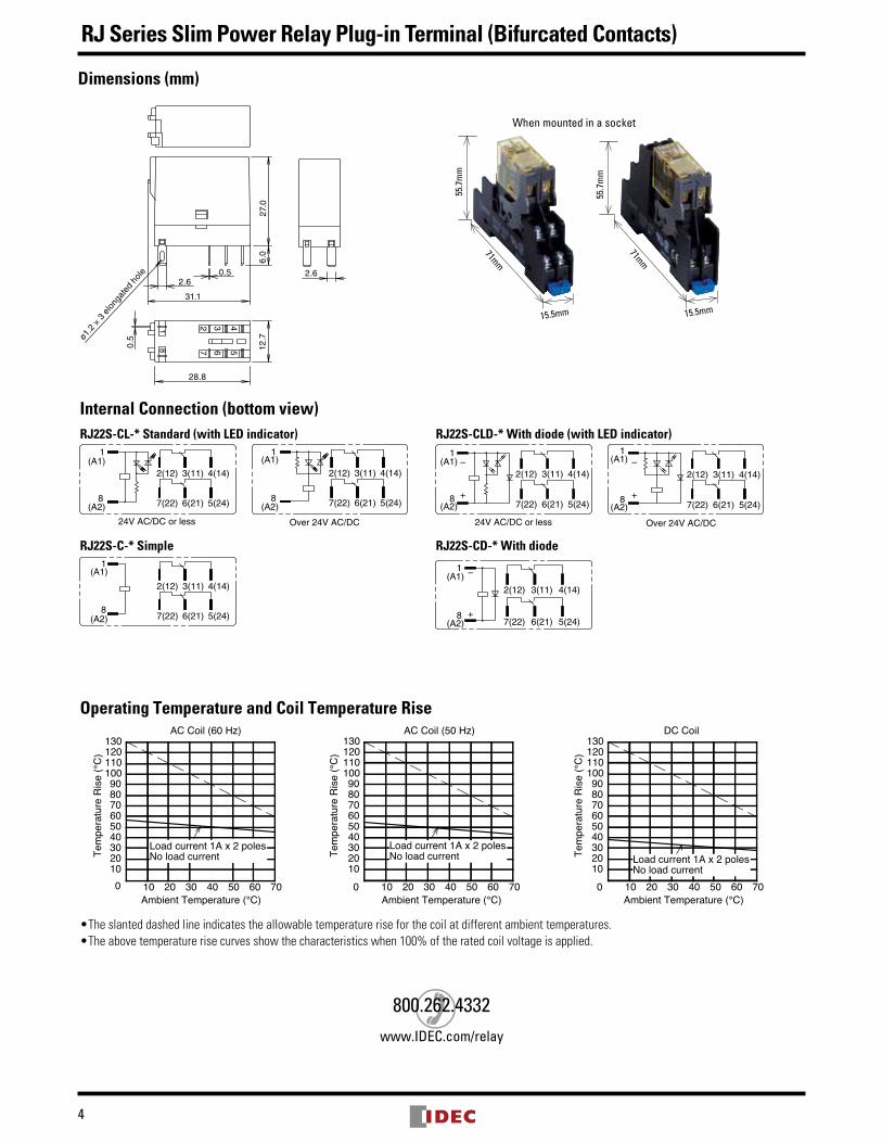
Internal Connection (bottom view)RJ22S-CL-* Standard (with LED indicator) RJ22S-CLD-* With diode (with LED indicator)
24V AC/DC or less Over 24V AC/DC
5(24)6(21)7(22)
4(14)3(11)2(12)
8(A2)
1(A1)
1(A1)
8(A2)
2(12) 3(11) 4(14)
7(22) 6(21) 5(24)
(A1)1
(A2)8
2(12) 3(11) 4(14)
7(22) 6(21) 5(24) 5(24)6(21)7(22)
4(14)3(11)2(12)
(A2)8
(A1)1
–
+
–
+
24V AC/DC or less Over 24V AC/DC
RJ22S-C-* Simple RJ22S-CD-* With diode
5(24)6(21)7(22)
4(14)3(11)2(12)
8(A2)
1(A1) (A1)
1
(A2)8
2(12) 3(11) 4(14)
7(22) 6(21) 5(24)
–
+
Operating Temperature and Coil Temperature Rise
Ambient Temperature (°C)Ambient Temperature (°C)Ambient Temperature (°C)
Tem
pera
ture
Ris
e (°
C)
Tem
pera
ture
Ris
e (°
C)
Tem
pera
ture
Ris
e (°
C)
AC Coil (60 Hz) AC Coil (50 Hz) DC Coil
0 10 20 30 40 50 60 70
102030405060708090
100110120130
Load current 1A x 2 polesNo load current
130120110100908070605040302010
706050403020100
Load current 1A x 2 polesNo load current
130120110100908070605040302010
706050403020100
Load current 1A x 2 polesNo load current
•Theslanteddashedlineindicatestheallowabletemperatureriseforthecoilatdifferentambienttemperatures.•Theabovetemperaturerisecurvesshowthecharacteristicswhen100%oftheratedcoilvoltageisapplied.
Dimensions (mm)
28.8
12.7
31.1
27.0
0.5ø1
.2 ×
3 e
long
ated
hol
e 0.52.6
6.0
2.6
7 6 5432
81
When mounted in a socket
71mm
15.5mm
55.7
mm
71mm
15.5mm
55.7
mm
800.262.4332www.IDEC.com/relay
5
RJ Series Slim Power Relay PC Board Terminal (Bifurcated Contacts)
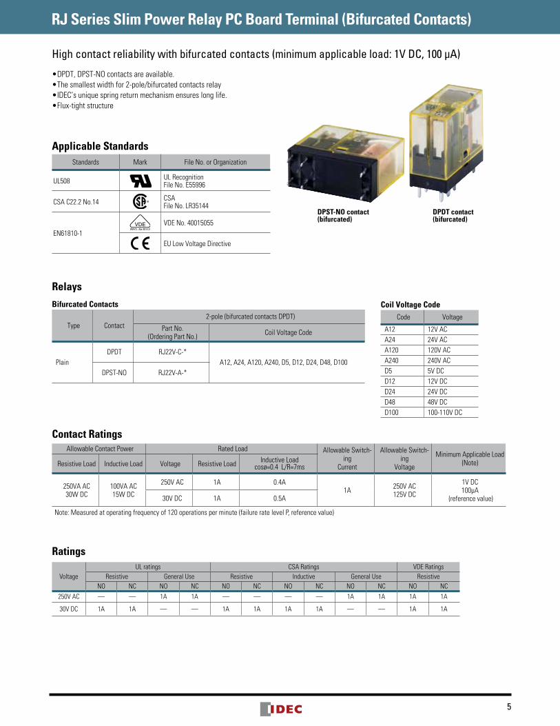
•DPDT,DPST-NOcontactsareavailable.•Thesmallestwidthfor2-pole/bifurcatedcontactsrelay•IDEC’suniquespringreturnmechanismensureslonglife.•Flux-tightstructure
Applicable StandardsStandards Mark FileNo.orOrganization
UL508 ULRecognitionFileNo.E55996
CSAC22.2No.14 CSAFileNo.LR35144
EN61810-1VDENo.40015055
EULowVoltageDirective
High contact reliability with bifurcated contacts (minimum applicable load: 1V DC, 100 µA)
Coil Voltage CodeCode Voltage
A12 12VACA24 24VACA120 120VACA240 240VACD5 5VDCD12 12VDCD24 24VDCD48 48VDCD100 100-110VDC
RelaysBifurcated Contacts
Type Contact2-pole(bifurcatedcontactsDPDT)
PartNo.(OrderingPartNo.) CoilVoltageCode
PlainDPDT RJ22V-C-*
A12,A24,A120,A240,D5,D12,D24,D48,D100DPST-NO RJ22V-A-*
Contact RatingsAllowableContactPower RatedLoad AllowableSwitch-
ingCurrent
AllowableSwitch-ing
Voltage
MinimumApplicableLoad(Note)ResistiveLoad InductiveLoad Voltage ResistiveLoad InductiveLoad
cosø=0.4L/R=7ms
250VAAC30WDC
100VAAC15WDC
250VAC 1A 0.4A1A 250VAC
125VDC
1VDC100μA
(referencevalue)30VDC 1A 0.5A
Note:Measuredatoperatingfrequencyof120operationsperminute(failureratelevelP,referencevalue)
Ratings
VoltageULratings CSARatings VDERatings
Resistive GeneralUse Resistive Inductive GeneralUse ResistiveNO NC NO NC NO NC NO NC NO NC NO NC
250VAC — — 1A 1A — — — — 1A 1A 1A 1A
30VDC 1A 1A — — 1A 1A 1A 1A — — 1A 1A
DPDT contact (bifurcated)
DPST-NO contact (bifurcated)
RJ Series Slim Power Relay PC Board Terminal (Bifurcated Contacts)
6
Coil Ratings
RatedVoltage(V)
CoilVoltageCode
RatedCurrent(mA)±15%(at20°C)
CoilResistance(Ω)±10%(at20°C)
OperatingCharacteristics(againstratedvaluesat20°C)
PowerConsumption
50Hz 60HzPickupVoltage
(initialvalue)
DropoutVoltage
(initialvalue)
MaximumContinuousApplied
Voltage(Note)
AC50/60Hz
12V A12 87.3 75.0 62.5
80%maximum
30%minimum 140%
Approx.1.1VA(50Hz)0.9to1.2VA(60Hz)
24V A24 43.9 37.5 243120V A120 8.8 7.5 6,400240V A240 4.3 3.7 25,570
DC
5V D5 106 47.2
70%maximum
10%minimum
170%160%
Approx.0.53to0.64W
12V D12 44.2 27124V D24 22.1 1,08048V D48 11.0 4,340
100-110V D100 5.3-5.8 18,870Note: Maximumcontinuousappliedvoltageisthemaximumvoltagethatcanbeappliedtorelaycoils.
SpecificationsRelay RJ22V
NumberofPoles 2-pole
ContactConfiguration DPDT(bifurcated),DPST-NO(bifurcated)
ContactMaterial AgNi(goldclad)
DegreeofProtection Flux-tightstructure
ContactResistance(initialvalue) 50mΩmaximum(measuredusing5VDC,1Avoltagedropmethod)
OperatingTime(at20°C) 15msmaximum(attheratedcoilvoltage,excludingcontactbouncetime)
ReleaseTime(at20°C) 10msmaximum(attheratedcoilvoltage,excludingcontactbouncetime)
InsulationResistance 100MΩminimum(500VDCmegger)
ImpulseWithstandVoltage 10,000VAC(betweencontactandcoil)
DielectricStrength
Betweencontactandcoil 5,000VAC,1minute
Betweencontactsofthesamepole 1,000VAC,1minute
Betweencontactsofthedifferentpoles 3,000VAC,1minute
VibrationResistance
OperatingExtremes 10to55Hz,amplitude0.75mm
DamageLimits 10to55Hz,amplitude0.75mm
ShockResistance
OperatingExtremes NOcontact:200m/s2,NCcontact:100m/s2
DamageLimits 1,000m/s2
ElectricalLife
ACload:100,000operationsminimum(operatingfrequency1,800perhour)DCload:200,000operationsminimum(operatingfrequency1,800perhour)
MechanicalLife
ACload:10millionoperationsminimum(operatingfrequency18,000operationsperhour)DCload:20millionoperationsminimum(operatingfrequency18,000operationsperhour)
OperatingTemperature(100%ratedvoltage) –40to+70°C(nofreezing)
OperatingHumidity 5to85%RH(nocondensation)
StorageTemperature –40to+85°C(nofreezing)
StorageHumidity 5to85%RH(nocondensation)
Weight(approx.) DPDT:17g,DPST-NO:16g
800.262.4332www.IDEC.com/relay
RJ Series Slim Power Relay PC Board Terminal (Bifurcated Contacts)
7
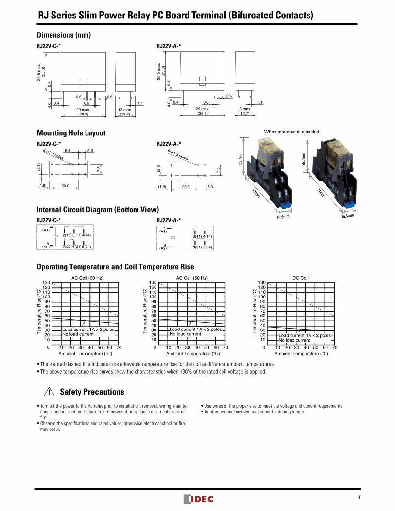
Dimensions (mm)RJ22V-C-*
13 max.(12.7)
1.1
4.0
0.3
25.5
max
.(2
5.3)
29 max.(28.8)
0.4
0.60.6
0.6
RJ22V-A-*
13 max.(12.7)
1.1
4.0
0.3
25.5
max
.(2
5.3)
29 max.(28.8)
0.4
0.6
0.6
Mounting Hole LayoutRJ22V-C-*
(2.6
)
8-ø1.3 holes
(1.9)
5.05.0
20.0
7.5
RJ22V-A-*
5.0
(2.6
)
(1.9) 20.0
7.5
6-ø1.3 holes
Internal Circuit Diagram (Bottom View)RJ22V-C-*
8(A2)
2(12) 3(11)
6(21)7(22) 5(24)
4(14)
1(A1)
RJ22V-A-*
8(A2)
3(11)
6(21) 5(24)
4(14)
1(A1)
Operating Temperature and Coil Temperature Rise
Ambient Temperature (°C)Ambient Temperature (°C)Ambient Temperature (°C)
Tem
pera
ture
Ris
e (°
C)
Tem
pera
ture
Ris
e (°
C)
Tem
pera
ture
Ris
e (°
C)
AC Coil (60 Hz) AC Coil (50 Hz) DC Coil
0 10 20 30 40 50 60 70
102030405060708090
100110120130
Load current 1A x 2 polesNo load current
130120110100908070605040302010
706050403020100
Load current 1A x 2 polesNo load current
130120110100908070605040302010
706050403020100
Load current 1A x 2 polesNo load current
•Theslanteddashedlineindicatestheallowabletemperatureriseforthecoilatdifferentambienttemperatures.•Theabovetemperaturerisecurvesshowthecharacteristicswhen100%oftheratedcoilvoltageisapplied.
Safety Precautions
•TurnoffthepowertotheRJrelaypriortoinstallation,removal,wiring,mainte-nance,andinspection.Failuretoturnpoweroffmaycauseelectricalshockorfire.•Observethespecificationsandratedvalues,otherwiseelectricalshockorfiremayoccur.
•Usewiresofthepropersizetomeetthevoltageandcurrentrequirements.•Tightenterminalscrewstoapropertighteningtorque.
When mounted in a socket
71mm
15.5mm
55.7
mm
71mm
15.5mm
55.7
mm
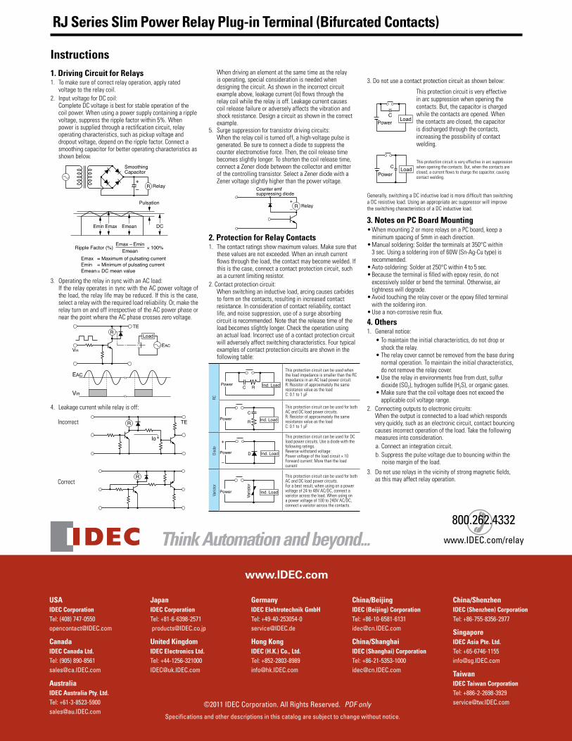
Instructions1. Driving Circuit for Relays1. Tomakesureofcorrectrelayoperation,applyrated
voltagetotherelaycoil.2. InputvoltageforDCcoil:
CompleteDCvoltageisbestforstableoperationofthecoilpower.Whenusingapowersupplycontainingaripplevoltage,suppresstheripplefactorwithin5%.Whenpowerissuppliedthrougharectificationcircuit,relayoperatingcharacteristics,suchaspickupvoltageanddropoutvoltage,dependontheripplefactor.Connectasmoothingcapacitorforbetteroperatingcharacteristicsasshownbelow.
+– R
SmoothingCapacitor
Relay
Pulsation
Emin Emax Emean DC
Ripple Factor (%) × 100%Emax – Emin
Emax = Maximum of pulsating currentEmin = Minimum of pulsating currentEmean= DC mean value
Emean
3. OperatingtherelayinsyncwithanACload: IftherelayoperatesinsyncwiththeACpowervoltageof
theload,therelaylifemaybereduced.Ifthisisthecase,selectarelaywiththerequiredloadreliability.Or,maketherelayturnonandoffirrespectiveoftheACpowerphaseornearthepointwheretheACphasecrosseszerovoltage.
R
VinEAC
TE
Load
Vin
EAC
4. Leakagecurrentwhilerelayisoff:Incorrect R TE
lo
CorrectR
Whendrivinganelementatthesametimeastherelayisoperating,specialconsiderationisneededwhendesigningthecircuit.Asshownintheincorrectcircuitexampleabove,leakagecurrent(Io)flowsthroughtherelaycoilwhiletherelayisoff.Leakagecurrentcausescoilreleasefailureoradverselyaffectsthevibrationandshockresistance.Designacircuitasshowninthecorrectexample.
5. Surgesuppressionfortransistordrivingcircuits:Whentherelaycoilisturnedoff,ahigh-voltagepulseisgenerated.Besuretoconnectadiodetosuppressthecounterelectromotiveforce.Then,thecoilreleasetimebecomesslightlylonger.Toshortenthecoilreleasetime,connectaZenerdiodebetweenthecollectorandemitterofthecontrollingtransistor.SelectaZenerdiodewithaZenervoltageslightlyhigherthanthepowervoltage.
R
Counter emfsuppressing diode
Relay+
–
2. Protection for Relay Contacts1. Thecontactratingsshowmaximumvalues.Makesurethat
thesevaluesarenotexceeded.Whenaninrushcurrentflowsthroughtheload,thecontactmaybecomewelded.Ifthisisthecase,connectacontactprotectioncircuit,suchasacurrentlimitingresistor.
2.Contactprotectioncircuit:Whenswitchinganinductiveload,arcingcausescarbidestoformonthecontacts,resultinginincreasedcontactresistance.Inconsiderationofcontactreliability,contactlife,andnoisesuppression,useofasurgeabsorbingcircuitisrecommended.Notethatthereleasetimeoftheloadbecomesslightlylonger.Checktheoperationusinganactualload.Incorrectuseofacontactprotectioncircuitwilladverselyaffectswitchingcharacteristics.Fourtypicalexamplesofcontactprotectioncircuitsareshowninthefollowingtable:
RC
PowerC R Ind. Load
ThisprotectioncircuitcanbeusedwhentheloadimpedanceissmallerthantheRCimpedanceinanACloadpowercircuit.R:ResistorofapproximatelythesameresistancevalueastheloadC:0.1to1μF
C
RPower Ind. Load
ThisprotectioncircuitcanbeusedforbothACandDCloadpowercircuits.R:ResistorofapproximatelythesameresistancevalueastheloadC:0.1to1μF
Diode
+
–
DPower Ind. Load
ThisprotectioncircuitcanbeusedforDCloadpowercircuits.Useadiodewiththefollowingratings.Reversewithstandvoltage:Powervoltageoftheloadcircuit×10Forwardcurrent:Morethantheloadcurrent
Varistor
Varis
tor
Power Ind. Load
ThisprotectioncircuitcanbeusedforbothACandDCloadpowercircuits.Forabestresult,whenusingonapowervoltageof24to48VAC/DC,connectavaristoracrosstheload.Whenusingonapowervoltageof100to240VAC/DC,connectavaristoracrossthecontacts.
3.Donotuseacontactprotectioncircuitasshownbelow:
PowerC
Load
Thisprotectioncircuitisveryeffectiveinarcsuppressionwhenopeningthecontacts.But,thecapacitorischargedwhilethecontactsareopened.Whenthecontactsareclosed,thecapacitorisdischargedthroughthecontacts,increasingthepossibilityofcontactwelding.
C LoadPower
Thisprotectioncircuitisveryeffectiveinarcsuppressionwhenopeningthecontacts.But,whenthecontactsareclosed,acurrentflowstochargethecapacitor,causingcontactwelding.
Generally,switchingaDCinductiveloadismoredifficultthanswitchingaDCresistiveload.UsinganappropriatearcsuppressorwillimprovetheswitchingcharacteristicsofaDCinductiveload.
3. Notes on PC Board Mounting•Whenmounting2ormorerelaysonaPCboard,keepaminimumspacingof5mmineachdirection.
•Manualsoldering:Soldertheterminalsat350°Cwithin3sec.Usingasolderingironof60W(Sn-Ag-Cutype)isrecommended.
•Auto-soldering:Solderat250°Cwithin4to5sec.•Becausetheterminalisfilledwithepoxyresin,donotexcessivelysolderorbendtheterminal.Otherwise,airtightnesswilldegrade.
•Avoidtouchingtherelaycoverortheepoxyfilledterminalwiththesolderingiron.
•Useanon-corrosiveresinflux.
4. Others1. Generalnotice:
•Tomaintaintheinitialcharacteristics,donotdroporshocktherelay.
•Therelaycovercannotberemovedfromthebaseduringnormaloperation.Tomaintaintheinitialcharacteristics,donotremovetherelaycover.
•Usetherelayinenvironmentsfreefromdust,sulfurdioxide(SO2),hydrogensulfide(H2S),ororganicgases.
•Makesurethatthecoilvoltagedoesnotexceedtheapplicablecoilvoltagerange.
2. Connectingoutputstoelectroniccircuits:Whentheoutputisconnectedtoaloadwhichrespondsveryquickly,suchasanelectroniccircuit,contactbouncingcausesincorrectoperationoftheload.Takethefollowingmeasuresintoconsideration.a.Connectanintegrationcircuit.b.Suppressthepulsevoltageduetobouncingwithinthenoisemarginoftheload.
3. Donotuserelaysinthevicinityofstrongmagneticfields,asthismayaffectrelayoperation.
©2011 IDEC Corporation. All Rights Reserved. PDF only
Think Automation and beyond...
Specifications and other descriptions in this catalog are subject to change without notice.
800.262.4332www.IDEC.com/relay
www.IDEC.com
USAIDEC CorporationTel: (408) [email protected]
CanadaIDEC Canada Ltd.Tel: (905) [email protected]
AustraliaIDEC Australia Pty. Ltd.Tel: [email protected]
JapanIDEC CorporationTel: +81-6-6398-2571 [email protected]
United KingdomIDEC Electronics Ltd.Tel: +44-1256-321000 [email protected]
GermanyIDEC Elektrotechnik GmbHTel: [email protected]
Hong KongIDEC (H.K.) Co., Ltd.Tel: +852-2803-8989 [email protected]
China/BeijingIDEC (Beijing) CorporationTel: [email protected]
China/ShanghaiIDEC (Shanghai) CorporationTel: [email protected]
China/ShenzhenIDEC (Shenzhen) CorporationTel: +86-755-8356-2977
SingaporeIDEC Asia Pte. Ltd.Tel: +65-6746-1155 [email protected]
TaiwanIDEC Taiwan CorporationTel: +886-2-2698-3929 [email protected]
RJ Series Slim Power Relay Plug-in Terminal (Bifurcated Contacts)


