64
SmartLink-G, SmartLink-GP GSM Dialler Programming Manual PATENT PENDING 0470

SmartLink-G, SmartLink-GPGSM Dialler
ProgrammingManual
PATENT PENDING
0470

Programming manual
2
CopyrightThe information contained in this document is the sole property of INIM Electronics s.r.l. No part may be copied without written authorization from INIM Electronics s.r.l.
All rights reserved.
Directive 1999/5/CE (R&TTE) compliance.
Hereby INIM Electronics s.r.l. declares that the SmartLink-G and SmartLink-GP are in compliance with the essential requirements and other relevant provisions of Directive 1999/5/CE.
The full declarations of conformity of the above-mentioned devices are available at URL:www.inim.biz/dc.html.

3
Programming manual
Table of contents
Chapter 1 Overview .....................................5Chapter 2 General information.......................6
2.1 In-box documentation 62.2 Manual details 62.3 Addressees 62.4 Software information 62.5 Intellectual property rights 62.6 Key 6
Chapter 3 Programming the SmartLink-GP ......83.1 Introduction 83.2 Installing the SmartLeague software 83.3 SmartLeague software 93.4 Recommended programming flow 123.5 Settting up contact data 133.6 Setting up the SmartLink parameters 183.7 Programming the Inputs and Outputs — IN&OUT 243.8 Programming the SmartLink-GP as anIntrusion control panel 293.9 Associating incoming and outgoing calls with actions 313.10 Programming event generated actions 343.11 Programming periodic events 433.12 Remote control of the SmartLink-GP via SMS text messages 443.13 Programming the device via SMS messages 473.14 Remote control of SmartLink-GP via DTMF tones 52
Appendix A Example wiring diagram intrusion con-trol ........................................... 57
Appendix B Features not managed by the Smart-Link-G model.............................. 59

4
Programming manual
Appendix C Default settings of the Smartlink-GP60Appendix D Inhibit events for output control ....61• Notes.........................................62

Overview 5
Programming manual
Chapter 1
Overview
The SmartLink is available in the following models:
• SmartLink-GP• SmartLink-G
Besides the features of the SmartLink-G model, the SmartLink-GP modelalso provides the following advanced features:
1. Intrusion control panel facility
2. Voice dialler (requires SmartLogos60 accessory board)
3. PSTN line call management
The Smartlink-G model does not provide these features.
This manual describes the Smartlink-GP features and programming process.SmartLink-G users can skip the sections which refer to the advancedfeatures.
Refer to Appendix B for a detailed list of the Smartlink-GP advanced featuresand flexibility-optimized software.
6 General information
Programming manual
Chapter 2
General information
2.1 In-box documentation• Installation manual• Programming manual (this manual)
The Installation manual is inside the device package. For extra copies of theinstallation manual, please contact INIM electronics specifying the order codeshown in the Installation manual Appendix B.
2.2 Manual detailsTitle: SmartLink-G and SmartLink-GP Programming Manual
• Edition,Version: 2.10• Month and Year of issue: October 2012• Code: DCMPINE0SLINK
2.3 Addressees • Installer• Technical assistance
2.4 Software information• Smartleague software version: 3.x.x• Firmware version : 2.x.x
2.5 Intellectual property rightsThe information contained in this document is private property. All rightsreserved.
No part of this document may be copied or reproduced unless expresslyauthorized in writing by INIM Electronics, in particular the parts regardingthe device specified in the Installation Manual paragraph 2.8 Device identifier
INIM Electronics s.r.l. shall not be responsible for damage arising fromimproper application or use.
2.6 Key
2.6.1 Glossary and terminologyDevice: refers to the device specified in the Installation Manual paragraph2.8 Device identifier.

General information 7
Programming manual
Left, right, behind, above, below: indications using the operator'sposition in front of the mounted device as the reference point.
Pulse output: same as "monostable output"
Dialler (phone, SMS, digital): same as "communicator"
Qualified personnel: those persons whose training, expertise andknowledge of the respective laws and bylaws regarding service conditionsand the prevention of accidents, are able to identify and avoid all possiblesituations of danger.
Click on: click to select a specific item (from drop-down menu, options box,graphic object, etc.).
Select: click on a video button.
2.6.2 Graphic keyText in italics: indicates the title of a chapter, section, paragraph, table orfigure in this manual or other published reference.
<text>: editable space, for example #<CustomerCode># may become#0001#.
[Uppercase letters] (e.g..[A]): indicate the device parts or video objects.
Note: The detached notes contain important information aboutthe respective text.
Attention: The attention prompts indicate that total or partialdisregard of the procedure could damage theconnected devices.
Danger: The danger warnings indicate that total or partialdisregard of the procedure could injure the operatoror persons in the vicinity.

8 Programming the SmartLink-GP
Programming manual
Chapter 3
Programming the SmartLink-GP
3.1 IntroductionThe SmartLink-GP can be programmed to manage:
• Intrusion control• SMS dialler• Contact ID Dialler• Remote appliance control• Voice dialler (optional feature)
Note: If the SmartLink-GP is used as a reserve line generator, noprogramming is required.
SmartLink-GP programming requirements:
• a portable computer for parameter downloading to the powered-up wall-mounted device
• RS232 link cable• SmartLeague software
3.2 Installing the SmartLeague software
3.2.1 Installing SmartLeague from the CDIf included in your purchase order, you will have the SmartLeagueInstallation CD containing the software for the respective SmartLink-GPfirmware. Check the software version, refer to Help, About SmartLeague.New versions of the SmartLeague software can be downloaded from the INIMelectronics Web address at www.inim.biz.
After installing the SmartLeague software, contact the Web address to findout about new versions. Internet connection required.
Installation instructions1. Insert the Installation CD into your service computer.
2. Select 'Computer Resources' on your desktop.
3. Find the CD unit, double click on the icon: the CD contents will bedisplayed.
4. Double click on Setup.exe: the Welcome to the installationprogram window appears.
5. Select 'Continue': the Folder selection window appears.

Programming the SmartLink-GP 9
Programming manual
Note: You should select the suggested folder.
6. Select 'Continue': file installation initializes, the progress bar willindicate completion.
Note: Always complete installation, do not select Cancel duringthe installation phase.
7. Once installation has been completed, the SmartLeague icon will appearon your desktop (if requested by the user) and in the program
list:
3.2.2 Check for the availability of a new version of the SmartLeague software.
8. Connect with us at www.inim.biz to find out about SmartLeaguesoftware upgrades.
9. View the differences between the new version and the installed version.
10. Work carefully through the upgrade instructions.
3.2.3 Check for the availability of a new version of the firmware.
11. Connect with us at www.inim.biz to find out about SmartLink-GPfirmware upgrades.
12. Work carefully through the download and installation instructions. Allupgrades come with the revised version of the manual.
3.3 SmartLeague softwareSmartLeague is the SmartLink-GP configuring software. The program isdesigned to run on your service computer and will allow you to programmost of the SmartLink-GP parameters without actually being connected tothe system.
Your service computer must be connected to the mounted powered-upSmartLink-GP during the parameter downloading phase.
The connection cable must be long enough to reach the mounted devicewithout difficulty. Refer to the Installation Manual - paragraph 7.13Connecting the RS232 PC serial link.
The parameter settings can be saved to the SmartLeague database and usedfor service purposes or as a 'standard configuration' for other SmartLink-GPdevices.
During service sessions, you will be able to view and change the SmartLink-GP parameter settings.

10 Programming the SmartLink-GP
Programming manual
3.3.1 General informationSmartLeague is the configuring software of the entire INIM electronicsproduct spectrum. You can configure numerous devices/systems on youroffice service computer, regardless of the type of device/system.
You can configure a device on your service computer, then write the data tothe device EEPROM when you get to the customer's premises.
You can work on several parameter groups ('solutions') at the same time, forexample, you can copy a device/system configuration and download it toanother device/system of the same type. Each solution has its ownconfiguration file:
If you wish to create a 'solution', you must first select the device type andmodel:
The start page of the SmartLeague software is connected to the INIM Webproviders, if you are connected to internet, it will show all the updatedinformation regarding software and firmware upgrades, revised manuals,instruction inserts and newsletters, etc.

Programming the SmartLink-GP 11
Programming manual
Note: To change the Web address of the page and reconnectioninterval, select Settings, Application data,Miscellaneous .
3.3.2 Setting up the computer serial outputUsing the Settings, Application data, Serial Ports menus, check that theselected settings match the serial cable you intend using for the computer toSmartLink-GP connection.
3.3.3 Configuring a new system1. Create a new solution (select File, New), or open a solution previously
used for a similar system (select File, Open), and save it in the name ofthe new customer with the new account code.
2. Customize the parameter settings.
3. Save (select File, Save) and if necessary, print the details (menu File,Print).
4. Connect the computer to the RS232 serial port of the device.
5. Download the 'solution' (configuration) to the device, select Program,Download): all six LEDs will blink during this phase.
Note: If an error occurs during the downloading phase, you mustrepeat the operation. The new data will overwrite theprevious configuration.
3.3.4 Programming an installed device1. Connect the computer to the RS232 serial port of the device.
2. Create a new solution (select File, New), or open the current solution(configuration) of the system (select File, Open).
3. To load the current parameters, select Program, Upload: all six LEDswill blink during this phase.
4. Customize the parameter settings.
5. Save (select File, Save) and if necessary, print the details (menu File,Print).
Download the 'solution' (configuration) to the device, select Program,Download: all six LEDs will blink during this phase.
Note: If an error occurs during the downloading phase, you willhave to repeat the operation. The new data will overwritethe previous configuration.

12 Programming the SmartLink-GP
Programming manual
3.3.5 Status enquiry1. Connect the computer to the RS232 serial port of the device.
2. Select Control panel, Status enquiry: a window appears showing theIMEI code, SIM data, installed version and battery, GSM network andinput statuses.
3. Select Send SMS, to send an SMS Test text from the SmartLink.
3.3.6 Viewing the Events log1. Connect the computer to the RS232 serial port of the device.
2. Create a new solution (select File, New), or open the current solution(configuration) of the system (select File, Open).
3. To view the contents of the events log, select Log.
4. Select the icon. The recorded events will appear on the bottom left.
5. The recorded events appear.
Note: The contents of the event log can be printed or saved to thedatabase.
3.3.7 Print1. Define the printout header (e.g. Logo, Company name, etc.).
2. To type in the respective data, select Printer settings, from Settings,Application settings.
3. Select the icon and click on the file you wish to print.
3.4 Recommended programming flowDue to the flexibility-optimized SmartLink-GP software, many ways ofpreparing the parameters exist, depending on the type of application.
Generally, you can proceed as follows.
1. Prepare the data:• phone numbers for Contact ID reports, SMS texts and voice messages• SMS text messages• voice messages• Caller ID codes
2. Configure the device parameters
3. Configure the inputs and outputs (for intrusion control and reserve lineapplications).
4. Associate the incoming/outgoing calls with specific actions.
5. Program the events which will:• Send pre-set SMS text messages• Send Contact ID reports• Send voice messages

Programming the SmartLink-GP 13
Programming manual
• Activate/Deactivate outputs• Generate constraint
6. Program periodic events
3.5 Settting up contact data
3.5.1 Settting up outgoing call numbers
Figure 1 - PhonebookThe SmartLink-GP sends outgoing Contact ID reports, voice message callsand event-generated SMS text messages (direct or diverted) to the 10 phonenumbers in the phonebook.
For example, Central station numbers for Contact ID reports or the phonenumbers for SMS text messages.
Note: International numbers must be entered in the followingformat: +xxyyyyyyyyy (e.g. “+390611111”).
To view events which generate outgoing calls to the phone numberconcerned, select ‘+’ next to the progressive number:

14 Programming the SmartLink-GP
Programming manual
3.5.2 Setting up the SMS dialler messages
Figure 2 - SMS tableThe SmartLink-GP manages 10 SMS text messages to communicaterecognized events (trouble, input status change, periodic events, etc.) to thenumbers in the Phonebook. For example, you can pre-set an SMS textmessage to warn users of 'flood below deck or basement flood'.
Note: When programming the SMS dialler, you must at leastdefine the SMS text message description, the text canbe entered successively.
Parameter Description Note
No. Phone number slot
Description Description which identifies the event-associated phone number.
Phone number
number including national and, if necessary, international phone code.
Diverted messages
Diverts SMS text messages from enabled phone numbers to the phone number (Divert SMS option from the Phone number functions table).
For example, this option will allow you to view which SMS text messages SmartLink-GP receives from the numbers concerned.
Parameter Description Note
No. SMS text message slot
Description The description which identifies the event-associated SMS text message.

Programming the SmartLink-GP 15
Programming manual
3.5.3 Setting up the voice dialler messages(requires SmartLogos60 voice board)
Figure 3 - Voice Message tableSmartLink-GP manages eight voice messages to communicate recognizedevents (trouble, input status change, periodic events, etc.) to the numbers inthe Phonebook.
Note: More than one voice message can be included in a singlecall. This option optimizes the voice message feature. Youcan create a group of event messages and a group ofmessages associated with the places the events may occur.
For example, as illustrated, you can select Msg4=“Attempted Tamper” andMsg6=“Jenner St offices" for one call and Msg3=“Attempted Intrusion” andMsg6=“Jenner St offices” for another call.
Note: The SmartLink will start the voice message as soon as therecipient answers the call.
Message Message text The underline in the message box indicates the maximum length of the message. 80 characters for messages 1 to 5; 40 characters for messages 6 to 10.
Parameter Description Note
No. Voice message slot assigned during the recording phase.
Description Description which identifies the event generated voice message.
Parameter Description Note

16 Programming the SmartLink-GP
Programming manual
Recording voice messagesYou can record the voice messages by connecting an ordinary touch-tonephone to connector J6 on SmartLogos60 board. Refer to the InstallationManual - paragraph 7.9 Connecting the SmartLogos60 (accessory item).
The recording procedure is as follows:

Programming the SmartLink-GP 17
Programming manual
3.5.4 Setting up Caller ID codes
Figure 4 - Codes tableThe SmartLeague application uses the installer, user and customer ID codesfor SMS or DTMF caller identification (Caller ID) and for SmartLink-GPidentification during Contact ID report transmissions to central stations.
Parameter Description Note
Installer code This is the access code that SmartLeague uses during communications with the SmartLink-GP.
User code This is the access code the user must enter in SMS text message or DTMF commands to the SmartLink-GP.
See paragraph 3.12 Remote control of the SmartLink-GP via SMS text messages and paragraph 3.14 Remote control of SmartLink-GP via DTMF tones.
Customer code
This is the code which identifies the SmartLink-GP during Contact ID report transmissions to central stations.
18 Programming the SmartLink-GP
Programming manual
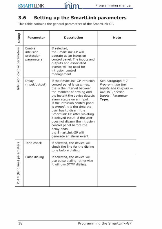
3.6 Setting up the SmartLink parametersThis table contains the general parameters of the SmartLink-GP.
Gro
up
Parameter Description Note
Intr
usio
n co
ntro
l par
amet
ers Enable
intrusion protection parameters
If selected,the SmartLink-GP will operate as an intrusion control panel. The inputs and outputs and associated events will be used for intrusion control management.
Delay(input/output)
If the SmartLink-GP intrusion control panel is disarmed, the is the interval between the moment of arming and the instant the device detects alarm status on an input.If the intrusion control panel is armed, it is the time the user has to disarm the SmartLink-GP after violating a delayed input. If the user does not disarm the intrusion control panel before the delay endsthe SmartLink-GP will generate an alarm event.
See paragraph 3.7 Programming the Inputs and Outputs — IN&OUT, section Inputs, Parameter Type.
PSTN
(la
nd li
ne)
para
met
ers Tone check If selected, the device will
check the line for the dialing tone before dialing.
Pulse dialing If selected, the device will use pulse dialing, otherwise it will use DTMF dialing.

Programming the SmartLink-GP 19
Programming manual
Trou
ble
war
ning
par
amet
ers Enable 'PSTN
(land line) down' warning
If selected, it will enable the Land line down event and visual signaling on the trouble LED.
Enable 'No GSM Service' warning
If selected, it will enable the No GSM Service event and visual signaling on the trouble LED.
Ans
wer
phon
e pa
ram
eter
s Enable land line (PSTN) answerphone
If selected, it will enable remote control of the device via DTMF tones on the land line (PSTN).
If SmartLink-GP is connected to a fax machine or modem, you must also enable the Double call option.
Enable GSM answerphone
If selected, it will enable remote control of the device via DTMF tones on the GSM network.
Enable Double Call
Useful if the SmartLink-GP is connected to a fax machine or modem that will answer after a set Number of rings.To stop a fax machine or modem from answering a DTMF maintenance call, first enable the Double call option then call the panel and hang up (the call rings must be less than the set Number of rings), make a second call within 60 seconds of hanging up. The SmartLink-GP will pick up the call on the first ring of the second call and will be ready to accept DTMF commands.
Only if Enable PSTN answerphone option has been selected.Program the fax machine or modem to answer after the set Number of rings.
Number of rings
The number of rings which must be detected before answering an incoming call.
Gro
up
Parameter Description Note

20 Programming the SmartLink-GP
Programming manual
Dia
ller
para
met
ers Call all
Contact ID numbers
If selected, the device will call alternately the two or more numbers associated with an event (to transmit Contact ID reports) until all numbers successfully receive the communication. If not selected, the device will call until one number only successfully receives the communication.
Call all voice numbers
Same as Call all Contact ID numbers, for voice message calls.
Confirm with * If enabled, the SmartLink will consider the voice call successful when the recipient presses “*” on the telephone keypad.
Bypass voice check
If enabled, the SmartLink will start the voice message 5 seconds after dialing the respective contact number.
Call attempts The maximum number of call attempts the SmartLink-GP will make when operating as a dialer. If a call is unsuccessful (i.e. unanswered) the SmartLink-GP will retry for the set number of call attempts.
From 1 to 10.
Replay message
Indicates the number of times voice messages must be played during a call. If, for example, a call includes messages 2 and 4 and the Replay message parameter is set at 5, messages 2 and 4 will be played five times before the Smartlink-GP ends the call.
From 1 to 10.
Gro
up
Parameter Description Note

Programming the SmartLink-GP 21
Programming manual
Dia
ling
para
met
ers Remove no.
digitsNumber of digits to be removed from the prefix of every phone number dialed on the GSM network.
Example: phone number 0039 02 111111, with Remove no. digits=4 result 02 111111
Add area code Area code consisting of numbers, '*' and '#' to be added to every phone number dialed on the GSM network.
Example: to be applied in countries where the area code is not required for local dialing but is necessary for GSM network calls.
Hidden call If selected, incoming and outgoing calls will not generate visual signals on the "Ongoing call" LED.
This feature is a useful way of hiding intrusion-panel generated communications from intruders.
Cre
dit
Para
met
ers Warning each
unit of remaining-credit used
If selected, the SmartLink will generate a “Low Credit” event when credit reaches the "Remaining credit level" and each time the remaining credit decreases by a further unit (£, €,$, etc.).
Example: If the “Remaining credit level” is £12 and the "Warning each unit of remaining-credit used" option has been selected, the first warning will appear when the balance reaches £11.90, then at £10.78 and £9.94, etc.
The functionality of the credit-notification process is subject to temporary or permanent unavailability due to the GSM provider.
Automatic credit residue notification
When the SIM credit goes below this value, the SmartLink will generate a “Low credit” event.
Gro
up
Parameter Description Note
22 Programming the SmartLink-GP
Programming manual
Oth
er p
aram
eter
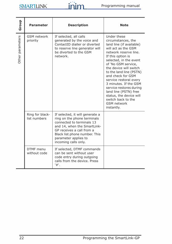
s GSM network priority
If selected, all calls generated by the voice and ContactID dialler or diverted to reserve line generator will be diverted to the GSM network.
Under these circumstances, the land line (if available) will act as the GSM network reserve line. If this option is selected, in the event of 'No GSM service, the device will switch to the land line (PSTN) and check for GSM service restoral every 3 minutes. If the GSM service restores during land line (PSTN) free status, the device will switch back to the GSM network instantly.
Ring for black-list numbers
If selected, it will generate a ring on the phone terminals connected to terminals 13 and 14, when the SmartLink-GP receives a call from a Black list phone number. This parameter applies to incoming calls only.
DTMF menu without code
If selected, DTMF commands can be sent without user code entry during outgoing calls from the device. Press '#'.
Gro
up
Parameter Description Note
Programming the SmartLink-GP 23
Programming manual
Oth
er p
aram
eter
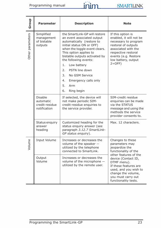
s Simplified management of bistable outputs
the SmartLink-GP will restore an event associated output automatically (restore to initial status ON or OFF) when the toggle event clears. This option applies to bistable outputs activated by the following events:
1. Low battery
2. PSTN line down
3. No GSM Service
4. Emergency calls only
5. Arm
6. Ring begin
If this option is enabled, it will not be necessary to program restoral of outputs associated with the respective restoral events (e.g. Restore low battery, output 2=OFF)
Disable automatic credit-residue notification
If selected, the device will not make periodic SIM-credit-residue enquiries to the service provider.
SIM-credit residue enquiries can be made via the STATUS message and using the methods the service provider consents to.
Status enquiry answer heading
Customized heading for the status enquiry answer (see paragraph 3.12.7 SmartLink-GP status enquiry).
Max. 12 characters.
Volu
me Input Volume Increases or decreases the
volume of the speaker — utilized by the telephone connected to SmartLink.
Changes to these parameters may jeopardize the functionality of the other features of the device (Contact ID, DTMF menu). If these features are used, and you wish to change the volume, you must carry out functionality tests.
Output Volume
Increases or decreases the volume of the microphone — utilized by the remote user.
Gro
up
Parameter Description Note

24 Programming the SmartLink-GP
Programming manual
3.7 Programming the Inputs and Outputs — IN&OUT
Figure 5 - Inputs/Outputs tableThe IN&OUT terminal board provides 5 terminals (5 to 9), each of which canbe used as an input or as an output or both. The Use as drop-down menuwill allow you to select the operating mode of the terminal.
SmartLeague refers to the terminals as “input” or “output” using thisnumeration:
Note: In this chapter the terminals are identified by their typeand number (e.g. input 1 or output 3).
Refer to the Installation Manual - paragraph 5.1 Terminal board for theterminal board.
3.7.1 InputsThe inputs can be used for devices with two statuses only (active-standby) orfor devices with three or four statuses (e.g. standby, alarm, tamper andshort-circuit).
The four statuses are determined by two termination resistors whichdetermine the three threshold windows. Each exceeded threshold generatesan event which can be associated with an outgoing SMS text message,Contact ID report, voice message or activation of outputs and constraint.

Programming the SmartLink-GP 25
Programming manual
Input default settingsThe SmartLink-GP input default settings determine the following conditions:
The default settings allow management of the normally closed (or open)contacts and the terminated line (EOL or DEOL), typical of intrusion controlpanels. See paragraph 3.8 Programming the SmartLink-GP as an Intrusioncontrol panel.
Note: To view the events associated with input status change,expand the structure by selecting ‘+’ next to the inputnumber:
3.7.2 OutputsThe Open-Collector, pulse or bistable outputs can also be programmed toactivate the external LEDs or buzzer. In this case, they will operate withspecific characteristics.
The outputs can be activated by:
• events generated by status changes on other outputs, or by internal events
• incoming calls from recognized phone numbers• incoming SMS text messages containing commands• DTMF tone sequences

26 Programming the SmartLink-GP
Programming manual
3.7.3 Inputs/OutputsThe IN&OUT terminals can operate as inputs or outputs.1
For example, during testing, you can command an output then check itsstatus (as an input) and verify the result (i.e. command received orcommand not received).
For example you can:
1. Using DTMF tones, activate output 2 — programmed as normally openand bistable.
2. Program event 8 (input 2, that is, the status of output 2) to send an SMStext message to toggle output 3 to ON status.
3. Result: the remote command will close output 2 to ground. The statuschange will be detected as the input of the event programmed to triggerthe “send SMS message” and “activate output 3” actions.
Note: If an input signal generates an output-activating event, adifferent terminal to the input signal terminal must beused.
1. Patent pending
Para
-m
eter
Description Note
Des
crip
tion The customizable name given to the
terminal. The identifier (or name) is necessary during remote-activation operations relating to one or more terminals via SMS messages.
Out
put
- Po
larity Output standby status Normally open,
normally closed (to ground).
Out
put
- Ty
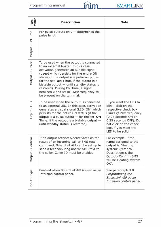
pe If the output is a pulse output, activation will change its status for the set time only. If the output is a bistable output, activation will change its status until the output is deactivated.
Pulse or bistable.For example, low battery event, bistable: the warning persists until the battery is properly charged. Pulse: the output generates a pulse to signal low battery status.
Programming the SmartLink-GP 27
Programming manual
Out
put
- O
N T
ime For pulse outputs only — determines the
pulse length.O
utpu
t -
Buz
zer To be used when the output is connected
to an external buzzer. In this case, activation generates an audible signal (beep) which persists for the entire ON status (if the output is a pulse output — for the set ON Time, if the output is a bistable output — until standby status is restored). During ON Time, a signal between 0 and 5V @ 1KHz frequency will be present on the terminal.
Out
put
- LE
D To be used when the output is connected to an external LED. In this case, activation generates a visual signal (LED ON) which persists for the entire ON status (if the output is a pulse output — for the set ON Time, if the output is a bistable output — until standby status is restored).
If you want the LED to blink, click on the respective check box. Blinks @ 2Hz frequency (0.25 seconds ON an 0.25 seconds OFF). Do not click on the check box, if you want the LED to be solid.
Out
put
- Con
firm If an output activates/deactivates as the
result of an incoming call or SMS text command, SmartLink-GP can be set up to send a feedback ring and/or SMS text to the caller. Caller ID must be enabled.
For example, if the name assigned to the output is "Heating system" (refer to Descriptions), the Output- Confirm SMS will be"Heating system OK".
Inpu
t -
Type Enabled when SmartLink-GP is used as an
Intrusion control panel.See paragraph 3.8 Programming the SmartLink-GP as an Intrusion control panel.
Para
-m
eter
Description Note

28 Programming the SmartLink-GP
Programming manual
Inpu
t -
Line
ter
min
atio
n Enabled when SmartLink-GP is used as an Intrusion control panel.
See paragraph 3.8 Programming the SmartLink-GP as an Intrusion control panel.
Inpu
t -
24h Enabled when SmartLink-GP is used as an
Intrusion control panel.See paragraph 3.8 Programming the SmartLink-GP as an Intrusion control panel.
Inpu
t -
Thre
shol
d 1 The value of the balance resistor which
determines the transition threshold from status 1 to status 2, and triggers the status 2 event.
Inpu
t -
Thre
shol
d 2 The value of the balance resistor which
determines the transition threshold from status 2 to status 3, and triggers the status 3 event.
Inpu
t -
Thre
shol
d 3 The value of the balance resistor which
determines the transition threshold from status 3 to status 4, and triggers the status 4 event.
Para
-m
eter
Description Note

Programming the SmartLink-GP 29
Programming manual
3.8 Programming the SmartLink-GP as anIntrusion control panel
Figure 6 - Inputs/Outputs table
Cal
ibra
tion The button used to calibrate an input and
reduce the effect of loss of component characteristics.a Proceed as follows:
1. Connect a calibration resistor (10K, 12K or 15K as required, between IN&OUT terminal concerned and ground (terminal 4).
2. Connect the SmartLink-GP to a computer.
3. Select the button in the Resistance column: the box will show the value read on the terminal.
4. If the value differs greatly from the value of the resistor connected to the terminal, proceed with the calibration. If the values are very similar, calibration will not be necessary.
5. Otherwise, select Calibrate: answer YES to the confirm request.
6. Click on the value of the resistor used then select Ok.SmartLink-GP compares the selected value and the current value on the input. It will indicate any notable difference and request confirmation to continue.
7. Wait 3-4 seconds: a calibration done message appears. Select the button in the Resistance column to verify the value on the terminal after calibration.
Send the parameters to SmartLink-GP before switching off. This is the only way to make the calibration definite!
Calibration is recommended on systems using dated components, in order to allow signals coming from these components to have values suitable to detect exceeded balance thresholds and subsequent status changes.
You can use the View button in the Resistance column at any time to view the value of the resistance on a specific terminal. The terminal open string indicates a value of over 30K.
a. Patent pending
Para
-m
eter
Description Note

30 Programming the SmartLink-GP
Programming manual
SmartLink-GP can operate as an intrusion control panel by simplyprogramming the inputs and outputs accordingly. For example:
In this example the keyswitch arms/disarms the intrusion control panel.During armed status, any status changes on the entrance and/or store roominputs — which occur after the programmable delay — will activate an alarmsounder and an external LED and will generate the voice and central stationcalls.
To set up the system as per this example, you must:
1. Enable the SmartLink-GP intrusion control panel option from theParameters, Intrusion control parameters table: in this way, input 5will be set up automatically to manage the keyswitch (normally open).
2. Program the other four terminals as inputs to monitor and outputs toactivate.
3. Program the events in the Events table for each status of the two inputsused.
Note: A typical connection for SmartLink-GP intrusion controlapplications can be found in the attached wiring diagram.See “Appendix A Example wiring diagram intrusioncontrol”. You can enable a phone number to arm/disarmthe system from remote locations (see Chapter 3 - 3.9Associating incoming and outgoing calls with actions)
Para
-m
eter
Description Note
Inpu
t -
Type Inputs with the Delayed attribute will not
generate the "status-change" event during the programmed delay (defined in Intrusion control panel parameters table). A series of slow beeps emitted by the buzzer indicate that the status change has been detected and the programmed delay is running. Inputs with the Instant attribute will signal status change instantly and will generate the respective event.
For example, the Entrance input is delayed long enough for the user to reach the arm/disarm keyswitch of the intrusion control panel at the entrance/exit of the premises.
Sounder

Programming the SmartLink-GP 31
Programming manual
3.9 Associating incoming and outgoing calls with actions
Figure 7 - Phone number functionsSmartLink-GP can identify up to 100 phone numbers. Caller ID can beapplied to incoming calls or SMS texts and outgoing calls. Caller ID must beenabled otherwise caller/sender identification will not be possible.
Incoming calls can either have no effect or be programmed to activate theoutputs or the incorporated buzzer. Incoming SMS texts can be diverted to apre-set number, used for status enquiries or to activate the outputs or theincorporated buzzer. Outgoing calls to black-list numbers can be barred. TheSmartLink-GP accepts five numbers with wildcard, that is, with the operator‘*’ that accepts any digit (e.g. “390611*” indicates all Rome numbers thatstart with “11”). The five numbers concerned must occupy the first fivepositions in the list.
SmartLink-GP does not answer incoming calls but on caller identification,generates the specified action (e.g. activate an output) and ends the call
Inpu
t -
Line
ter
min
atio
n The line termination type determines the logic of the intrusion control panel input statuses:
Inpu
t -
24h If 24h is not selected, only Short-circuit
and Tamper will be monitored during panel disarmed status. If 24h is selected, all conditions will be monitored, even when the panel is disarmed.
For example, this option is useful for duress and device tamper reports.
Para
-m
eter
Description Note
32 Programming the SmartLink-GP
Programming manual
only when a feedback ring is required (see paragraph 3.7.3 Inputs/Outputs).In other cases, the call will proceed normally.
If Caller ID is disabled, the SmartLink-GP will be unable to identify the caller,therefore, will manage the call as a normal call.
Attention: SmartLink-GP can identify these numbers duringincoming calls or SMS texts or outgoing calls, on theGSM network only.
Note: For wildcard numbers, indicate the numbers with andwithout the international code (e.g. “390611*” and“0611*”).
For all other numbers, you can enter the number with orwithout the respective international code).
For examples refer to the respective parameters in the following table.
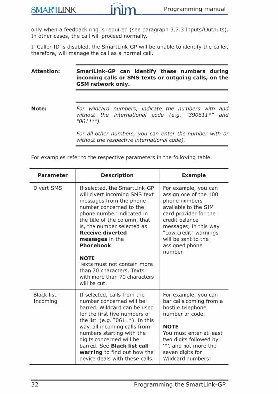
Parameter Description Example
Divert SMS If selected, the SmartLink-GP will divert incoming SMS text messages from the phone number concerned to the phone number indicated in the title of the column, that is, the number selected as Receive diverted messages in the Phonebook.
NOTETexts must not contain more than 70 characters. Texts with more than 70 characters will be cut.
For example, you can assign one of the 100 phone numbers available to the SIM card provider for the credit balance messages; in this way “Low credit" warnings will be sent to the assigned phone number.
Black list - Incoming
If selected, calls from the number concerned will be barred. Wildcard can be used for the first five numbers of the list (e.g. “0611*). In this way, all incoming calls from numbers starting with the digits concerned will be barred. See Black list call warning to find out how the device deals with these calls.
For example, you can bar calls coming from a hostile telephone number or code.
NOTEYou must enter at least two digits followed by ‘*’, and not more the seven digits for Wildcard numbers.

Programming the SmartLink-GP 33
Programming manual
Black list - Outgoing
If selected, calls to the number concerned will be barred. Wildcard can be used for the first five numbers of the list. In this way, all outgoing calls to numbers starting with the digits concerned will be barred.
For example, you can bar outgoing calls to 'pay numbers' (e.g. "1661212", "899*", etc.).
NOTEYou must enter at least two digits followed by ‘*’, and not more the seven digits for Wildcard numbers.
Caller ID — Outputs 1-5
If selected, the call coming from the number concerned will activate the corresponding output. The output must be configured as a pulse output in the Inputs/Outputs window.
For example, you can program a call to open a gate or garage.
NOTEIf an output has already been associated with one of the events included in Appendix D Inhibit events for output control, it cannot be used as a command output.
Caller ID - Buzzer
If selected, a call from the number concerned will activate the SmartLink-GP buzzer which will emit 3 beeps at one second intervals. If the call is from a black list number, the SmartLink-GP will emit 5 audible signals.
For example, to signal calls from nuisance callers or specific phone numbers.
Caller ID - Arm- Dis.
If selected, and if the intrusion control facility of the SmartLink is operating, incoming calls from the number concerned will arm/disarm the panel (input 5) and end automatically. The panel will send a feedback ring.
For example, to avoid using the keyswitch.
NOTEThe panel will send a 4 to 8 second feedback ring as confirmation of the performed arm/disarm operation.
Parameter Description Example

34 Programming the SmartLink-GP
Programming manual
3.10 Programming event generated actions
Figure 8 - Events tableThe events are the core of the system and allow SmartLink-GP to manageexternal conditions (e.g. input signals) and internal conditions (e.g. lowbattery). The events can generate the following actions:
Enable SMS without user code - Out
If selected, SmartLink-GP will accept SMS text commands (to activate/deactivate one or more IN&OUT outputs) from the number concerned without User code entry. The action/s will be as per the setup in the Inputs/Outputs window. See paragraph 3.12.3 Change user code and paragraph 3.5.4 Setting up Caller ID codes.
For example, to allow the central station operator to bar entrance to the premises.
Enable SMS without user code - Buzzer
If selected, SmartLink-GP will accept SMS text commands — to activate the buzzer — from the number concerned without User code entry. See paragraph 3.12.6 Activating the on-board buzzer and paragraph 3.5.4 Setting up Caller ID codes.
For example, to allow the central station operator to activate the buzzer and warn people on the SmartLink-GP protected premises of nuisance situations.
Enable SMS without user code - Status
If selected, SmartLink-GP will accept SMS text status enquiries from the number concerned without User code entry. See paragraph 3.12.7 SmartLink-GP status enquiry.
For example, to allow the service technician to check the SIM credit balance and battery status.
Parameter Description Example

Programming the SmartLink-GP 35
Programming manual
• Send SMS text message• Send Contact ID report• Send voice message • Activate/Deactivate outputs• Constraint and commands
The SmartLink-GP manages four status-change events per IN&OUT input(i.e. 20 events) and other pre-set events generated by SmartLink-GP.
Note: Among such events are trouble restoral events such as:Low battery restored. Bistable outputs toggled to ONstatus by an event must be restored to OFF status, forexample Low battery. Or use the Simplifiedmanagement option. See “paragraph 3.7 Programmingthe Inputs and Outputs — IN&OUT”.
Calls triggered by internal events will take priority over any calls sentthrough the SmartLink by the device on terminals 13 and 14. Therefore,calls coming from the device concerned will be interrupted automatically, if adialer-trigger event occurs (Voice, SMS or Contact ID. If several events occurat almost the same time, SmartLink-GP will create a Call queue and will dealwith the calls in chronological order.
For example, an input short-circuit event can be programmed to activate anoutput which will act on the shorted device. Or, an Incoming black listnumber event can be programmed to send a voice message.
Parameter Description
No. Event number
Description Event description
Intrusion input logic status
Enabled when SmartLink-GP is used as an Intrusion control panel. This shows the statuses (Standby, Alarm, Short-circuit and Tamper) the input manages in accordance with the balance type selected in the Inputs/Outputs table.
Save event If selected, the event concerned will be saved to the SmartLink-GP event log with the respective date, time and description. The log stores 32 events. Once the log is full, new events will automatically overwrite the oldest events in the log. The stored events are available for viewing in the Log table, and can be viewed separately from the other parameters. See paragraph 3.3.6 Viewing the Events log.

36 Programming the SmartLink-GP
Programming manual
3.10.1 Delete event programmingThe event programming can be deleted, for example, if programming errorsoccur.
To perform this operation, select, bottom left, Delete, click-on one or moregroups then select Delete: all the selected boxes will be deleted.
3.10.2 Send event-triggered voice message (SmartLogos60 required)
Figure 9 - Events table - Voice messagesEach event can trigger and send one or more voice messages to a specificphone number.
To allow this, the voice messages must be set up as per the instructions inparagraph 3.5.3 Setting up the voice dialler messages (requiresSmartLogos60 voice board). In this way, the description of the message tosend will appear in the message list.
For example, to warn one or more persons of active intrusion.
Parameter Description Note
Voice dialler Folder containing 'send voice message' parameters. Double click to open: columns containing the successive parameters will appear. Double click to close.
=no parameter has been set
=some parameters have been set.
Voice messages
Check boxes corresponding to the voice messages defined in the Voice message table. The message description appears when you mouse over the respective number on the tooltip bar. You can select several voice messages to be played one after another. For example, you can record a single "address" message to be added to all the event messages.

Programming the SmartLink-GP 37
Programming manual
3.10.3 Send event-triggered SMS text
Figure 10 - Events table - SMSEach event can trigger and send an SMS text message to a specific phonenumber.
To allow this, the SMS text messages must be defined as per the instructionsin paragraph 3.5.2 Setting up the SMS dialler messages. In this way, thedescription of the SMS text to-be-sent will appear in the SMS menu.
For example, to warn the service technician about low battery status.
Phone numbers
Check boxes corresponding to the phone numbers for outgoing calls set up in the Phonebook. The phone number description appears when you mouse over the respective number on the tooltip bar.
See the Call all voice numbers option to choose whether the message must reach only one of the dialed phone numbers or all of them successfully.
Parameter Description Note
SMS dialler Folder containing 'send SMS text message' parameters. Double click to open: columns containing the successive parameters will appear. Double click to close.
=no parameter has been set
=some parameters have been set.
SMS text List of SMS text messages (pre-set in the SMS table) available for the event.
Phone numbers
Check boxes corresponding to the phone numbers for outgoing calls set up in the Phonebook. The phone number description appears when you mouse over the respective number on the tooltip bar.
Parameter Description Note

38 Programming the SmartLink-GP
Programming manual
3.10.4 Send an event-triggered Contact ID report
Figure 11 - Events table - Contact IDEach event can trigger and send a Contact ID report to a specific phonenumber.
For example, an input zone alarm event to the central station.
Parameter Description Note
Contact ID dialler
Folder containing Contact ID report parameters. Double click to open: columns containing the successive parameters will appear. Double click to close.
=no parameter has been set
=some parameters have been set.
Protocol class
ContactID protocol class The event protocol class must be approved by the central station.
Event code 2 digit hexadecimal code The Code must be approved by the central station.
Qualifier New for a new event, Restored for a cleared event. In report coding New=1 and Restore=3.
Phone numbers
Check boxes corresponding to the phone numbers for outgoing calls set up in the Phonebook. The phone number description appears when you mouse over the respective number on the tooltip bar.
See the Call all Contact ID numbers option to choose whether the message must reach only one of the dialed phone numbers or all of them successfully.

39 Programming the SmartLink-GP
Programming manual
Note: The code which allows the central station to identify thesystem must be entered in the Codes window (refer toparagraph 3.5.4 Setting up Caller ID codes).
Setting Contact ID at defaultSelect Default Contact ID bottom left: SmartLink-GP will apply Contact IDdefault configuration to all events.
The event default codes are DCS (Digital Communication Standard)international reporting protocol, for example:
Indicates
• 3=trouble• A2=Low Battery• 1=New event
Note: You can create “model” solutions tailored to the needs ofspecific central stations, for each solution you can:1. select default Contact ID reporting protocol2. customize the Codes to central station requirements3. print the Contact ID table using File, Print.
Using the SmartLink-GP as an intrusion control panel
The event associated with status change on input 5 (arm/disarm intrusionpanel) does not have a Contact ID code.
The events associated with status change on the inputs will have Contact IDcodes which depend on the logic status of the input and its balance:
Event Protocol class Event code Qualifier
Low battery
3 A2 1
Input logic status Intrusion control
Protocol class
Event code Qualifier
Alarm 1 3A 1
Standby 1 3A 3
Tamper 1 44 1
Short-circuit 1 44 1

40 Programming the SmartLink-GP
Programming manual
3.10.5 Activate an output in response to an event
Figure 12 - Events table - OutputsEach event can activate/deactivate a pulse or bistable output.
To allow this, the outputs must be set up beforehand as per the instructionsin paragraph 3.7 Programming the Inputs and Outputs — IN&OUT. In thisway, the output description will appear in the selectable Outputs list.
For example, if an event occurs on an input connected to flood detectors, itwill be possible to cut off the water supply at the mains.
Attention: Bistable outputs (activated by events) do notdeactivate automatically when the event clears. Youmust program deactivation by selecting therespective 'restore' event. Or use the Simplifiedmanagement option. See paragraph 3.7Programming the Inputs and Outputs — IN&OUT.
Parameter Description Note
Outputs Folder containing the output activation parameters. Double click to open: columns containing the successive parameters will appear. Double click to close.
=no parameter has been set
=some parameters have been set.
ON Check boxes corresponding to the Inputs/Outputs configured in the Outputs table. If selected, they will activate the respective output. The output description appears when you mouse over the respective number on the tooltip bar.
If the output is a pulse output, activation will change its status for the set time only.

Programming the SmartLink-GP 41
Programming manual
3.10.6 Implement constraint after event
Figure 13 - Events table - ConstraintEach event can implement constraint and generate commands. Forexample, a No GSM Service event will switch dialing to the land line(PSTN).
OFF Check boxes corresponding to the Inputs/Outputs configured in the Outputs table. If selected, they will deactivate the respective output. The output description appears when you mouse over the respective number on the tooltip bar.
Deactivation of a pulse output ends any ongoing pulse signal, otherwise, it has no effect.
Parameter Description Note
Options Folder containing Constraint parameters. Double click to open: columns containing the successive parameters will appear. Double click to close.
=no parameter has been set
=some parameters have been set.
Land line (PSTN) constraint
If selected, all outgoing calls (voice messages and Contact ID reports) generated by the event will be sent on the land line (PSTN), thus ignoring the SmartLink-GP reserve line feature and GSM network priority option.
If this option is selected, the device will be unable to make any calls associated with the event during 'land-line down' conditions.
Parameter Description Note

42 Programming the SmartLink-GP
Programming manual
GSM network constraint
If selected, all outgoing calls (voice messages and Contact ID reports) generated by the event will be sent on the GSM network, even when the land line (PSTN) is working.
If this option is selected, the device will be unable to make any calls associated with the event during 'No GSM Service' conditions.
Clear call queue
If selected, this event will interrupt the ongoing call and cancel any event generated calls.
For example, this option is useful when users want to stop unnecessary calls generated by false alarms.
Periodic warning constraint
If selected, this event will generate a Programmable periodic event.
Within limits, for events relating to input 4, this parameter has the competency to "Divert all calls to the GSM network for 3 minutes.
Hide outgoing call
If selected, the visual/audible ongoing call signal will be hidden when the event occurs: • LED On• Start call event• End call eventIf, for the Start call and End call events, you select Save event, these events will be saved even if the audible/visual signal has been excluded.
For example, if you want to hide SmartLink-GP calls to the central station during a robbery.
Parameter Description Note

Programming the SmartLink-GP 43
Programming manual
3.11 Programming periodic events
Figure 14 - Programmable events tableYou can program recurring events and pre-set events. The Events listprovides three programmable events: a periodic event (e.g. Send 'All's well'Contact ID report) and two events with pre-set dates (e.g. Send SMS text orvoice message 'Maintenance' and/or SIM expiry reminders).
The programming of this window done is independent of all otherprogramming and it starts by selecting the Initialize button.
Parameter Description Note
Periodic event The periodic event will be generated automatically in accordance with the date and time entered in the Date/Time programming field. The successive periodic events will be generated in accordance with the number of hours entered in the Interval programming field.
For example, to send an 'All's well' Contact ID report to the central station.SmartLink-GP must be connected to a computer in order to implement this operation.
Maintenance event
SmartLink-GP will trid.gger the Maintenance event in accordance with the set date and time.
For example, to send SMS text 'Maintenance' reminder to the installer.

44 Programming the SmartLink-GP
Programming manual
Note: The examples are only suggestions. The programmableevents are fully customizable.
3.12 Remote control of the SmartLink-GP via SMS text messages
SmartLink-GP can manage SMS text commands from remote phones usingthe GSM network:
• Arm or disarm the system• activate one or more outputs• activate the buzzer• send SMS text reply to status enquiry
Attention: If an output has already been associated with one ofthe events included in Appendix D Inhibit events foroutput control, it cannot be used as a commandoutput.
Observe the spaces which separate the user code. Commands in uppercasetext.
3.12.1 Commands without user codeSmartLink-GP will accept incoming SMS commands without user code entry,from phone numbers which have been duly programmed under Phone
Expiry event SIM
SmartLink-GP will trigger the SIM expiry event in accordance with the set date and time.
For example, to send SMS text 'SIM expiry' reminder to the user.
NOTE Only for Italian GSM operators:Each time you top up your SIM card credit (using a pre-paid phonecard), SmartLink will update the reminder date, in such way as to match the new expiry date of the SIM card (renewed each time you top up credit).
Parameter Description Note

Programming the SmartLink-GP 45
Programming manual
number functions (see paragraph 3.9 Associating incoming and outgoingcalls with actions).
3.12.2 Sending several commands in one SMS text message
Several commands can be included in the same message (maximum 70characters). A space will separate one command from the other.
Example<User Code> <OutputDescription_x> ON <OutputDescription_y> OFFSTATUS
Example “0001 CourtesyLights ON GardenSprinkler OFF STATUS”
If a feedback reply is required, the message will read: "CourtesyLights OKGardenSprinkler OK”
3.12.3 Change user codeCODE <User Code> <NewUserCode>
Example“CODE 0001 000123”
Note: For security reasons, the respective SMS message will bedeleted automatically from the SIM card after acquisition.
This command allows the user to change the user code at any time.
3.12.4 Arm/Disarm panel• Arming the panel
SYSTEM ON• Disarming the panel
SYSTEM OFF• Password protected arming operations
<UserCode> SYSTEM ON• Password protected disarming operations
<UserCode> SYSTEM OFF
Example“0001 SYSTEM ON”
Note: The panel will send a 4 second (approx.) feedback ring tothe caller as confirmation of the performed arm operation,or an 8 second (approx.) feedback ring as confirmation ofthe performed disarm operation.

46 Programming the SmartLink-GP
Programming manual
3.12.5 Activating an Output<User Code> <OutputDescription_x> ON<User Code> <OutputDescription_y> OFF
Example“0001 CourtesyLights ON”
Attention: Use the correct format (uppercase/lowercase/space) for the output description. If the activatedoutput is a monostable output, the 'ON' commandwill initialize a normal monostable cycle.
If the output has been programmed, in the Inputs/Outputs table, toprovide a feedback reply, SmartLink-GP will send an SMS text or ring asrequired. See paragraph 3.7 Programming the Inputs and Outputs —IN&OUT.
If a feedback reply is required, the message will read: "CourtesyLights OK”
3.12.6 Activating the on-board buzzer<UserCode> BEEP x<UserCode> BEEP
X represents the duration in seconds of the on-board buzzer signal (from 1 to7). If x is omitted or the format is incorrect, the buzzer will emit 3 beeps atone second intervals.
Example“0001 BEEP 5”
If the output has been programmed, in the Inputs/Outputs table, toprovide a feedback signal, SmartLink-GP will send an SMS text or ring asrequired. See paragraph 3.7 Programming the Inputs and Outputs —IN&OUT.
If an SMS feedback reply is required, the message will read: “BEEP OK”
3.12.7 SmartLink-GP status enquiry<UserCode> STATUS
SmartLink-GP will answer this message with the respective information:
• Inputs status• Land line (PSTN) status• GSM network status• Battery status • On/Off Status• SIM credit balance
Example of status enquiry:“0001 STATUS”

Programming the SmartLink-GP 47
Programming manual
Example of SmartLink-GP answer:INIM SmartLink-GP Rev. x.xx: IN x-x-x-x-x ; PSTN aa; GSM aa; PWR aa; SYSaa; <GSM operator> REMAINING CREDIT ee.ee Euro
Note: Several commands can be sent in the same SMS message,therefore, you can send multi-command messages similarto the following:“OUT1 ON BEEP 5 OUT2 ON STATUS OUT4OFF SYSTEM ON” (for a maximum of 70 characters).
3.13 Programming the device via SMS messages
The installer can carry out minor operations using the SIM card, such as:
• program an output• program an event• insert/change an SMS message
Parameter Description Note
Rev. x.xx Installed firmware version
IN x-x-x-x-x The input slot (1,2,3,4,5) will show the respective status number (1=status 1, 2=status 2, etc.).
Example: IN 2 1 1 4 indicates Input 1=status 2, input 2=status 1, etc.
PSTN aa Land line (PSTN) status OK=line working, KO= line down or trouble
GSM aa GSM network status OK=line working, KO= line down or trouble
PWR aa Battery status OK=battery charged, KO= battery down
SYS aa (for GP models only, if the Intrusion Control facility is active)
Panel status. ON=armed, OFF=disarmed
<GSM operator> REMAINING CREDIT ee.ee Euro
Credit enquiry reply from GSM provider

48 Programming the SmartLink-GP
Programming manual
• set generic parameters• insert/change a number in the phonebook
Programming can be online, with the SmartLink On, via SMS messages, oroffline, with the SmartLink Off using a mobile phone to program the SIMcard.
The maximum number of SMS messages you can use depends on the SIMcard. Specifically: <SIMCapacity> -10 (e.g. if the SIM card can contain 40SMS messages, you can use as many as 30).
Attention: If you enter a parameter using less digits thanrequired (e.g.: “0100” instead of “01000” to enableoutput 2), the parameter will be ignored.
Note: Parameters that you do not wish to change can be omittedif they are at the end of the message (e.g.:“EastLight,NO,B”). However, you must leave the ‘,’(commas) if the unaltered parameters are not at the end ofthe message (e.g.: “EastLight,NO,B,102,,,3”).
Where unspecified 0=disabled, 1=enabled.
3.13.1 Programming online via SMSProceed as follows:
1. Send the <InstallerCode> PRG ON message: SmartLink will initialize theprogramming phase.
2. All the LEDs will blink.
3. Send the programming messages.
4. Send the <InstallerCode> PRG OFF message.
Programming online via SMS may last up 60 minutes. All the 24h inputs(refer to paragraph 3.8 Programming the SmartLink-GP as an Intrusioncontrol panel) will be forced to standby status during the programmingphase. This will allow the installer to carry out maintenance work on theSmartLink without generating alarms.
If the number of SMS messages sent during the programming phase exceedsthe limit, the SmartLink will ignore those in excess and will exit theprogramming phase.
Attention: If you do not close the programming session usingthe “PRG OFF” message, the 24h inputs will remainblocked until the 60 minute programming timeexpires.

Programming the SmartLink-GP 49
Programming manual
Note: The SMS messages can be sent in any order.If you wish to restore the factory default settings, youmust first delete the SMS messages from the SIM card andthen short-circuit the pins (refer to paragraph Defaultsettings of the Smartlink-GP).The installer code is required at all times.
3.13.2 Programming Offline via SIM cardWork carefully through the following steps:
1. Switch Off the SmartLink.
2. Remove the SIM card and put it into a mobile phone.
3. Create and Save all the messages you wish to store on the SIM card.
4. Re-insert the SIM card into the SmartLink and switch it On.
On powerup, the SmartLink will store all the messages on the SIM card andwill change all the settings accordingly.
If the number of SMS messages saved during the Offline session exceeds theSIM card capacity (<SIMCapacity> -10), the SmartLink will ignore those inexcess.
If you wish to program the remaining SMS messages, you can repeat theprocedure. However, you should not do so until the initializing phase of theSmartLink has ended properly.
3.13.3 Programming an outputSL OUT<OutputNum> <OutputDescription_x>,<Polarity>,<Type>,<ONTime>,<Buzzer>,<LED>,<Feedback>
Example“SL OUT1 EastLight,NO,B,102,0,0,3”
Parameter Description
OutputNum From 1 to 5
OutputDescription Description
Polarity NO=Normally openNC=Normally closed
Type B=bistableI=Pulse
OnTime in seconds
Buzzer 0=output1=output with Buzzer feature

50 Programming the SmartLink-GP
Programming manual
Note: Refer to paragraph 3.7 Programming the Inputs andOutputs — IN&OUT for the parameter descriptions.
3.13.4 Programming an eventSL EV <EventNum> <VoiceNum>,<SMSNum>,<VoiceMsg>,<SMSmsg>,<OUT_ON>,<OUT_OFF>,<PSTNConstraint>,<GSMConstraint>,<ClearCallQueue>
Example“SL EV33 0000000001,0000000010,00010100,2,00100,00010,0,0,0”
Note: The programming fields (e.g.: 00000001) refer to theposition of the element in the software interface (e.g.:1000000000 is telephone number 1, 0000000001 istelephone number 10). An event programmed via SIM hasthe Store event option enabled at all times. Refer to paragraph 3.10 Programming event generatedactions for the parameter descriptions
LED 0=output1=output with LED feature
Feedback 0=None1=SMS2=Rings3=SMS+ring
Parameter Description
EventNum From 1 to 46
VoiceNum Programming field to enable/disable the 10 voice-message telephone numbers
SMSNum Programming field to enable/disable the 10 SMS-message telephone numbers.
VoiceMsg Programming field to enable/disable the eight voice messages.
SMSmsg SMS Message
OUT_ON Programming field to enable the five outputs.
OUT_OFF Programming field to disable the five outputs.
Parameter Description

Programming the SmartLink-GP 51
Programming manual
3.13.5 Write/Change SMS messageSL MS<SMSnum> <SMSText>
Example“SL MS7 Warning detector tamper”
Note: Refer to paragraph 3.5.2 Setting up the SMS diallermessages for the parameter descriptions.
3.13.6 Setting the generic parametersSL PAR <PSTNdown>,<CallAllVoice>,<Tonecheck>,<RemoveDigits>,<AddAreaCode>,<InstallerCode>,<EnablePSTNanswerphone>,<EnableGSManswerphone>, <DoubleCall>,<NumberofRings>
Example“SL PAR 1,0,1,4,0735,2273,1,0,1,4”
PSTNConstraint 0= the event signals will be forwarded through the channel currently in use1= switches event signals to the PSTN network
GSMConstraint 0= the event signals will be forwarded through the channel currently in use1= switches the event signals to the GSM network
ClearCallQueue 0= the event will not effect the calls in the queue1= the event will clear the call queu
Parameter Description
SMSnum From 1 to 10.
SMSText SMS messages from 1 to 5 accept a maximum of 80 characters, the remaining messages accept 40 characters.
Parameter Description
PSTNdown Enables PSTN line-down signslling
CallAllVoice Calls all voice dialler numbers
Parameter Description

52 Programming the SmartLink-GP
Programming manual
Note: For security reasons, the respective SMS message will bedeleted automatically from the SIM card after acquisition.Refer to paragraph 3.6 Setting up the SmartLinkparameters for the parameter descriptions.
3.13.7 Write/Change telephone numberSL NUM<TelephoneNum> <number>
Example“SL NUM2 063333133”
Note: Refer to paragraph 3.5.1 Settting up outgoing call numbersfor the parameter descriptions.
3.14 Remote control of SmartLink-GP via DTMF tones
The SmartLink-GP will accept DTMF tone commands from remote phones,during incoming calls (user to SmartLink-GP) and outgoing calls (SmartLink-GP to user) on the PSTN or GSM network for:
• Arm/Disarm Intrusion Control Panel• Input status enquiry
Tonecheck Monitors line tone
RemoveDigits Number of digits
AddAreaCode Prefix to add
InstallerCode Installer’s code
EnablePSTNanswerphone Enables PSTN answerphone
EnableGSManswerphone Enables GSM answerphone
DoubleCall Enables Double Call answer
NumberofRings Number of Rings
Parameter Description
TelephoneNum Location in Phonebook, 1 to 10
number Number changed
Parameter Description

Programming the SmartLink-GP 53
Programming manual
• Activate output• Clear call queue
If the Enable GSM answerphone option has been selected, SmartLink-GPwill answer incoming DTMF tones on the GSM network. If the Enable PSTNanswerphone option has been selected, SmartLink-GP will answerincoming DTMF tones on the land line (PSTN). If neither of these options hasbeen selected, DTMF tones will be ignored. Both options can be enabledcontemporarily.
Note: For land line (PSTN) calls, check the setting of the Doublecall option. See “paragraph 3.7 Programming the Inputsand Outputs — IN&OUT”.
If you are making an status enquiry call to SmartLink-GP, or you arereceiving for example a 'flood alarm' voice call from SmartLink-GP, you willautomatically access DTMF mode which, in the case of the 'flood alarm' call,will allow you to turn off the water supply at the mains.
3.14.1 Sending the DTMF tone sequence
If you are calling the SmartLink-GP via GSM network or PSTN:1. Make the call.
If SmartLink-GP is calling you:1. Press ‘#’
Access the DTMF menu:2. Wait for 4 feedback beeps (access confirmed)
3. #UserCode# (e.g. “#005122#”)
4. Wait for a feedback beep (access confirmed)
5. Press ‘#’ to access the DTMF menu
6. Type in a Control code (‘0’, ‘1’, ‘4’, ‘5’)
7. Work carefully through the specific instructions for each code, asfollows.
Note: If (from the parameters table) the DTMF menu withoutcode option is enabled, and you receive a call from thedevice, you can omit the user code from the sequence, byskipping stepa 3, 4, 5.
Note: Press ‘#’ at any point to go back to the main menu or ‘*’ toend the call.

54 Programming the SmartLink-GP
Programming manual
3.14.2 Arm or disarm the system (#1)Enabled only when the Intrusion control feature has been duly programmed.
Note: The panel will send a 4 to 8 second feedback ring asconfirmation of the performed arm/disarm operation.

Programming the SmartLink-GP 55
Programming manual
3.14.3 Input status enquiry (#4)After initializing the menu, type in “#4”: the input reading will return 1 to 4beeps depending on the input status:

56 Programming the SmartLink-GP
Programming manual
3.14.4 Activating outputs (#5)After initializing the menu, type in “#5”:
Note: The output will not change status when you press thenumber key, but when you press # to confirm theoperation. If an output has already been associated withone of the events included in Appendix D , it cannot beused as a command outputInhibit events for output controlIf you attempt to command the output, the device will emitan audible error signal bop.
3.14.5 Clear call queue and end ongoing call (#0)After initializing the menu, type in “#0”: the device will end the ongoing calland cancel the calls in the queue.
3.14.6 End ongoing callAfter initializing the menu, type in ‘*’: the device will end the ongoing call.
3.14.7 Go back to main menuAfter initializing the menu, type in ‘#’: the device will get ready to receiveother DTMF tone commands.

Example wiring diagram intrusion control 57
Programming manual
Appendix A
Example wiring diagram intrusion control

58 Example wiring diagram intrusion
Programming manual
Caption• All resistors @ 15K• Normally-open keyswitch contact • Siren activated by "positive removed"• Device must be Earthed (see terminal 12)
Input programming:IO1-IO2Type: DelayedBalance: DEOLEvents 1, 2, 4, 5, 6, and 8 switch output 4 ONEvents 3 and 7 switch output 4 OFF
IO3Balance: EOLEvents 9, 11 and 12 switch output 4 ON Event 10 switches output 4 OFF
Outputs programming:IO4Type: BistablePolarity: normally open
IO5Already programmed by the selected parameter Enable intrusion control
The diagram illustrates an application with:
• Two DEOL zones for:- two detectors (e.g. infrared, magnetic contacts, etc.)- tamper and alarm return to the same input
• One balanced tamper zone for: - horn tamper detection- frontplate removal detection
• one alarm output, where the open-collector output controls a single polarity changeover relay:- self-powered external bell command- internal bell command
• keyswitch input to arm/disarm intrusion control panel

Features not managed by the SmartLink-G model 59
Programming manual
Appendix B
Features not managed by the SmartLink-G modelFeatures and settings not provided by the SmartLink-G model
Land line (PSTN) interface
The device performs voice and/or digital dialler and land-line (PSTN) answerphone functions.
Tone check Checks for the dialing tone before dialing a number
Pulse dialing Sets pulse dialing mode on the land line (PSTN)
Land-line answerphone and DTMF command management
Answers land line (PSTN) calls and manages a group of DTMF activated commands.
Access to DTMF menu without code
Allows access to the DTMF command menu without user code entry.
GSM priority Uses the GSM network during GSM Service Available status. Switches to the land line (PSTN) during No GSM Service status
Land line (PSTN) as GSM network reserve line
You can use the land line (PSTN) as GSM network reserve line.
Connecting the SmartLogos60 board
The SmartLogos60 board provides all voice features.
GSM network voice dialler Sends voice messages on the GSM network in response to recognized events.
Land line (PSTN) voice dialler
Sends voice messages on the PSTN network in response to recognized events.
Call all voice numbers If a SmartLogos60 is installed, generates calls to all the pre-set voice dialler numbers.
Control panel Works as a control panel
Programming entry parameters
Useful programming for the control panel feature.
Delay Allows an entry/exit delay when the control panel is in service.

60 Default settings of the Smartlink-GP
Programming manual
Appendix C
Default settings of the Smartlink-GPSmartLink-GP default settings:
• Credit limit: € 5;• Status message header: “INIM S_LINK”;• All the IN&OUT terminals are bistabile, normally- open outputs.• All events will be saved to the Events log.
The following events generate output actions:
Enabled Parameters:• Enable PSTN line-down warning;• Enable No GSM Service warning;• Simplified management of bistable outputs.
Codes• Installer code 0000• User code 0001• Customer code 0001
Restoring the device to factory default settingsShort-circuit pins 2 and 3 of the DB9 connector and power up the board.After 1 second the board parameters, including any input calibrations, will berestored to default settings.

Inhibit events for output control 61
Programming manual
Appendix D
Inhibit events for output control(via DTMF, SMS or recognized caller) If an output in the Events table has been associated with one of thefollowing events, it can be activated/deactivated only by another event andnot by DTMF tones, SMS text or recognized caller.
• Start dialler calls• Low battery• Call queue full• Disarm• Called failed on land line (PSTN)• Called failed on GSM network• Dialer calls ended• Arm• No GSM Service• Land line down (PSTN)• Power-on• Low battery restored• PSTN line restored• No GSM Service restored• Emergency calls only restored• Emergency calls only

62 Notes
Programming manual
Notes


INIM Electronics s.r.l.
via Fosso Antico, Centobuchi63033 Monteprandone, AP - Italy
Tel. +39 0735 70 50 07Fax. +39 0735 70 49 12
email: [email protected]
ISO9001:2000 REGISTERED COMPANY
DCMPINE0SLINK-R210-20121016


