OG_SLR-434SC_v11e Circuit Design, Inc. 1 Embedded low power radio modem SLR-434M Smart RF modem Serial communication Operation Guide Version 1.1 (Sep. 2018) Circuit Design, Inc. 7557-1 Hotaka, Azumino, Nagano, Japan Tel: 0263-82-1024 Fax: 0263-82-1016 e-mail: [email protected]http://www.circuitdesign.jp
4. Wireless data transmission commands and data transmission responses .............................. 13
4.1 Basic format of data transmission commands and responses .................................................... 13
5. Error responses to data transmission commands ....................................................................... 14
5.1 Basic format of error responses................................................................................................... 14
OG_SLR-434SC_v11e Circuit Design, Inc.3
6. Information responses (LoRa command mode only) ................................................................... 14
6.1 Basic format of information responses......................................................................................... 14
6.2 Response to carrier sensing (only with LoRa command mode) .................................................. 14
6.3 Response to correlation sensing (only with LoRa command mode) ........................................... 15
6.4 Data transmission complete response (only with LoRa command mode) .................................. 15
7. Receive data from the target station .............................................................................................. 16
7.1 Basic format of received data....................................................................................................... 16
8. Contact function ............................................................................................................................... 17
8.1 Basic format of control commands and control responses.......................................................... 17
8.2 “@PI” Set Unique ID for contact communication ......................................................................... 188.2.1 Check Unique ID currently set.............................................................................................. 188.2.2 Set to 'Not using Unique ID' (factory setting)........................................................................ 188.2.3 Set Unique ID to the local station ......................................................................................... 188.2.4 Receive Unique ID and set it as its own Unique ID.............................................................. 198.2.5 Transmit Unique ID .............................................................................................................. 198.2.6 Unique ID setting examples.................................................................................................. 19
8.3 “@PS” Set input/output port......................................................................................................... 20
8.4 “@PO” Set and acquire the local station port status.................................................................... 218.4.1 Set the status of the local station port................................................................................... 218.4.2 Acquire the status of the local station port............................................................................ 22
8.5 “@PT” Set and acquire the target station port status .................................................................. 238.5.1 Acquire the status of the target station port .......................................................................... 238.5.2 Set the status of the target station port................................................................................. 23
8.6 “@PM” Set contact function communication mode...................................................................... 248.6.1 Specified times transmission mode when changing input ports (LoRa/FSK command mode)....................................................................................................................................................... 248.6.2 One-way continuous transmission mode (FSK command mode only) ................................ 258.6.3 Two-way continuous communication mode (FSK command mode only)............................. 25
8.7 “@PF” Set output port holding time ............................................................................................. 25
8.8 Contact function responses ......................................................................................................... 268.8.1 "PR" response....................................................................................................................... 268.8.2 'PD' response........................................................................................................................ 288.8.3 Combination of the 'PR' and 'PD' responses........................................................................ 28
10. Channel plan ................................................................................................................................... 32
11. Data transmission time in the FSK/LoRa mode .......................................................................... 34
11.1 Data transmission time in the FSK mode................................................................................... 34
11.2 Data transmission time in the LoRa mode ................................................................................ 34
11.3 Data transmission time............................................................................................................... 36
OG_SLR-434SC_v11e Circuit Design, Inc.4
1. SummaryThe smart RF modem SLR-434M enables you to send and receive data or contact signal
wirelessly, with various parameters set via the serial port of a PC using proprietary commands.
This operation guide explains how to operate the SLR-434M using the commands.
For the details of the SLR-434M, refer to the operation guide "SLR-434M".
2. Control commands and control responses
2.1 Basic format of control commands and control responses
• Control command basic format
Prefix + command name + value + [CR] + [LF]
Prefix: ‘@’=40h, a code that indicates the start of the command string.
Command name: A code of 2 ASCII characters.
Values: A code of 2 ASCII characters corresponding to each command.
• Control response basic format
Prefix + command name + [=] + value + [CR] + [LF]
Prefix: ‘*’ = 2Ah, a code that indicates the start of the response string.
Command name: A code of 2 ASCII characters for the received command.
Values: A code of 2 ASCII characters corresponding to each command.
/W option
Values set with the commands can also be saved.If the value set for each command is saved, the set value becomes the initial value next timethe power is switched on.To save the value, add “/W” to the basic command format above.
Prefix + command name + value + [/] + [W] + [CR] + [LF]
If you save the values set with the commands, the following response is output before theresponse basic format above.
[*] + [W] + [R] + [=] + [P] + [S] + [CR] + [LF]
If you save the value set, wait for the “*WR=PS” response before switching the power off.
Acquiring the currently set value
If you did not add a value in the command basic format, the currently set value is output inaccordance with the response basic format.
OG_SLR-434SC_v11e Circuit Design, Inc.5
2.2 “@CH” Set frequency channel
Sets the frequency channel to be used.
The default setting at shipment is ‘4’'A’ (434.000 MHz).
Input the 2-character ASCII code after ‘@CH’ to set the channel.
Values: ‘0’ ‘0' - ‘8’ ‘8’ (A hexadecimal ASCII code showing channels from 0 to 136)
Example: Change to 0Eh (change to channel 14)
Control command: @CH0E
Control response: *CH=0E
* Refer to the channel table in “10. Channel plan”.
2.3 “@MO” Set radio communication mode
Sets the wireless communication mode.
There are the following 5 types of wireless communication mode.
The default setting at shipment is ‘0’ ‘3’ (LoRa command mode).
Input the 2-character ASCII code after ‘@MO’ to set the communication mode.
Values: ‘0’ ‘0’: FSK binary mode
‘0’ ‘1’: FSK command mode
‘0’ ‘2’: LoRa binary mode
‘0’ ‘3’: LoRa command mode
‘0’ ‘4’: Air monitor mode
Example: Change to 01h (Change to the FSK command mode)
Control command: @MO01
Control response: *WR=PS
*MO=01
*If a wireless communication mode is set, the setting is automatically saved and the device
restarts. (Even if the "/W" option is not used, the response "*WR=PS" is returned. )
Mode Content Value
FSK binary mode A mode with FSK modulation for use as a transparent modem. 00
FSK command modeA mode with FSK modulation for sending and receiving data usingproprietary commands.
01
LoRa binary mode A mode with LoRa modulation for use as a transparent modem. 02
LoRa command modeA mode with LoRa modulation for sending and receiving datausing proprietary commands.
03
Air monitor modeA mode for measuring the RSSI level of each channel.*a separate application is needed.
04
OG_SLR-434SC_v11e Circuit Design, Inc.6
After restarting, the following string is output to the serial port.
“FSK BIN MODE”: When set to the FSK binary mode
“FSK CMD MODE”: When set to the FSK command mode
“LORA BIN MODE”: When set to the LoRa binary mode
“LORA CMD MODE”: When set to the LoRa command mode
“AIR MONITOR MODE”: When set to the air monitor mode
*When set to the FSK binary mode or the LoRa binary mode, commands are not accepted asthe SLR-434M works as a transparent modem.If you want to change the mode, set the INI terminal of the SLR-434M to Low for at least 3seconds (See "SLR-434M" operation guide).
* When you changed the communication mode, wait for the string such as "LORA CMDMODE" that is output after restarting before you turn off the power.
2.4 “@SF” Set the number of chips (spreading factor) with LoRamodulation
Sets the number of chips for LoRa modulation.
The default setting at shipment is ‘0’ ‘0’ (128 chips).
Input the 2-character ASCII code after ‘@SF’ to set the number of chips.
*As the number of chips increases, the impact of the Doppler effect becomes greater when
moving around, and communication becomes less reliable.
2.5 “@EI” Set Equipment ID
Sets the individual ID for each device.
The default setting at shipment is ‘0’ ‘1’.
Input the 2-character ASCII code after ‘@EI’ to set the ID.
Values: ‘0’ ‘0' - ‘F’ ‘F’ (A hexadecimal ASCII code showing values from 0 to 255)
Example: Change to 0Ah (Set the Equipment ID to 10)
Control command: @EI0A
Control response: *EI=0A
OG_SLR-434SC_v11e Circuit Design, Inc.7
2.6 “@DI” Set Target station ID
Specifies the target station to communicate with.
The default setting at shipment is ‘0’ ‘1’.
Input the Equipment ID of the target station after ‘@DI’ with the 2-character ASCII code.
Values: ‘0’ ‘0' - ‘F’ ‘F’ (A hexadecimal ASCII code showing values from 0 to 255)
Example: Change to 0Ah (Set the Target station ID to 10)
Control command: @DI0A
Control response: *DI=0A
*If the Target station ID is set to ‘0’ ‘0’ and transmitted, communication changes to multi-addresscalling within the Group.
*When performing communication with one base unit and several slave units (1:Ncommunication), the base unit can communicate with a specific slave unit by specifying theEquipment ID set for the slave unit as the target station with the @DI command..
See “2.14 Building a communication system between radio stations” for details.
2.7 “@GI” Set Group ID
The Group ID is the ID that identifies a group in the user system. Set the same Group ID for all
the radio stations within the group. Maintain Group IDs as identification numbers when building
other systems.
The default setting at shipment is ‘0’ ‘0’.
Input the 2-character ASCII code after ‘@GI’ to set the ID.
Values: ‘0’ ‘0' - ‘F’ ‘F’ (A hexadecimal ASCII code showing values from 0 to 255)
Example: Change to 0Ah (set the Group ID to 10)
Control command: @GI0A
Control response: *GI=0A
2.8 “@UI” Set User ID
User identification ID assigned to a user. Communication is not possible unless all equipment
within the user system is set with the same User ID. When a single user builds multiple systems,
they are identified with a Group ID.
The setting command is ‘@UI + User ID + ‘,’ + password.
The default setting at shipment is ‘0’ ‘0’ ‘0’ ‘0’.
It can be used without User IDs, however, we recommend that you set a User ID to prevent
radio interference within a given area. If you require User IDs, please contact Circuit Design, Inc.
Input the 4-character ASCII code after ‘@UI’ to set the ID, and after ‘,’ enter a 4-character ASCII
code password.
Example: Control command: @UI0000,XXXX (XXXX is the password part)
Control response: *WR=PS
*UI=0000 (To set back to 0000, input 2367 for password.)
* When the UI command is issued, the setting is automatically saved and the device restarts.
(Even if the "/W" option is not used, a *WR response is returned. )
OG_SLR-434SC_v11e Circuit Design, Inc.8
2.9 “@RS” Acquire RSSI for the last data received
If this command is implemented immediately after receiving data, you can acquire the Received
Signal Strength Indicator (RSSI) value when the data was received. The output format for the
RSSI value is as follows.
*RS=###dBm (The ### part is the RSSI value when the data was received)
Example: Control command: @RS
Control response: *RS=-82dBm
2.10 “@RA” Acquire the current RSSI value
Acquires the current Received Signal Strength Indicator (RSSI) value of the channel set.
*RA=###dBm (The ### part is the RSSI value when the data was received)
Prefix: ‘*’ = 2Ah, a code that indicates the start of the error response string.Error string: ‘E’ ’R’, a code of 2 ASCII characters.Error code: A code of 2 ASCII characters representing an error code corresponding to each command.
Note:In wireless communication, the longer data length you use, the higher communication errorprobability there will be. Try to minimize the data length.It is recommended to use a data length of 45 bytes or less in the FSK command mode.(In the FSK command mode, if the size of transmission data exceeds 45 bytes, the data is sentin several packets.)
Prefix: ‘*’ = 2Ah, a code that indicates the start of the error response string.Error string: ‘E’ ’R’, a code of 2 ASCII characters.Error code: A code of 2 ASCII characters representing an error code corresponding to each command.
The details of the error codes are shown in the table below.Error code Content
“03” Output if the format of the data transmission command is wrong.
“01” Output when the error code is not “03”.
6. Information responses (LoRa command mode only)
When the LoRa command mode is set, an information response is output if the device cannot emitradio waves due to carrier sensing or correlation sensing and when data transmission completes.In other communication modes such as FSK command mode, FSK binary mode, LoRa binarymode, the information response is not output.
Prefix: ‘*’ = 2Ah, a code that indicates the start of the information response string.Information string: ‘I’ ’R’, a code of 2 ASCII characters.Response code: A code of 2 ASCII characters representing each response.
If RSSI output during carrier sensing is enabled with '@CI01', the RSSI value is output followingthe above response.(The RSSI value is also output when transmission is performed with the '@PT' command or'@PMxx' command. )
Example) When the RSSI value is -110 dBm[R] + [S] + [S] + [I] + [=] + [-] + [1] + [1] + [0] + [d] + [B] + [m] + [CR] + [LF]
6.3 Response to correlation sensing (only with LoRa command mode)
With LoRa modulation, communication is possible at levels lower than city noise, so it is not
possible to check for the presence of other LoRa modulation radio waves before emitting with
the carrier sensing in 6.2 alone.
Therefore, the SLR-434M uses a proprietary method called correlation sensing to check for the
presence of other LoRa modulation radio waves before emitting waves.
When correlation sensing determines that transmission is not possible due to the presence of
other LoRa modulation radio waves, the character string “*IR=02” is output after the data
transmission response.
If data cannot be transmitted, it is not retransmitted.
8. Contact functionThe SLR-434M enables you to transmit and receive contact data wirelessly using the DIO
terminals and proprietary commands
This chapter explains the contact function and the commands used for contact data
communication. For the DIO terminals, refer to the operation guide "SLR-434M".
For safety operation of the contact function, it is recommended to set a user ID ('@UI') and a
Unique ID ('@PI').
(The PI command was added to the FW version 1.081 and later.)
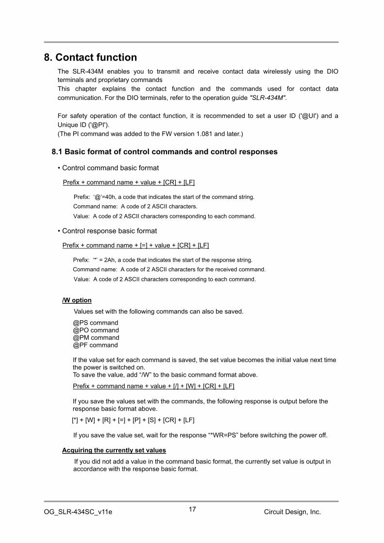
8.1 Basic format of control commands and control responses
• Control command basic format
Prefix + command name + value + [CR] + [LF]
Prefix: ‘@’=40h, a code that indicates the start of the command string.
Command name: A code of 2 ASCII characters.
Value: A code of 2 ASCII characters corresponding to each command.
• Control response basic format
Prefix + command name + [=] + value + [CR] + [LF]
Prefix: ‘*’ = 2Ah, a code that indicates the start of the response string.
Command name: A code of 2 ASCII characters for the received command.
Value: A code of 2 ASCII characters corresponding to each command.
/W option
Values set with the following commands can also be saved.
@PS command@PO command@PM command@PF command
If the value set for each command is saved, the set value becomes the initial value next timethe power is switched on.To save the value, add “/W” to the basic command format above.
Prefix + command name + value + [/] + [W] + [CR] + [LF]
If you save the values set with the commands, the following response is output before theresponse basic format above.
[*] + [W] + [R] + [=] + [P] + [S] + [CR] + [LF]
If you save the value set, wait for the response “*WR=PS” before switching the power off.
Acquiring the currently set values
If you did not add a value in the command basic format, the currently set value is output inaccordance with the response basic format.
OG_SLR-434SC_v11e Circuit Design, Inc.18
8.2 “@PI” Set Unique ID for contact communication
Setting the Unique ID for contact communication ensures safety operation of the contactfunction.All radio stations in a system need to be set with the same Unique ID.Since the serial number individually allocated to the SLR-434M unit is read out and used as theUnique ID, the user cannot use the Unique IDs allocated to the units other than the units theyown. This prevents malfunctions due to interference with other users.
Identification by setting '@ EI', '@ DI', '@ GI', '@ UI', that is explained in the previous sections, isalso available in contact data communication. However, since the IDs other than User ID can beset to any value, there is a possibility that radio stations set with the same ID accidentallycommunicate each other.Identification by the Unique ID can be freely set and used by the user.
The serial number of the SLR-434M consists of 1 alphabetical letter and 7-digit numbers. Theserial number described below means the 7-digit numbers.
8.2.1 Check Unique ID currently set
Control command: @PIExample 1) Control response: * PI=000000 (000000 means the Unique ID is set to 'Not using'.)Example 2) Control response: * PI=12D687 (When the Unique ID is set, the ID is returned.
12D687 (Hex) = 1234567)
* When the Unique ID is used, 3-byte data is added to the data format, resulting in a longertransmission time.
8.2.2 Set to 'Not using Unique ID' (factory setting)
Control command: @PICControl response: *WR=PS (This response means the setting is saved.)
*PI=000000 (Cleared to 000000)
8.2.3 Set Unique ID to the local station
Set the Unique ID to the local station with its own serial number.
Example) When the SLR-434M of the local station has "S/No. A1234567" on its label.
Control command: @PISControl response: *WR=PS (This response means the setting is saved.)
*PI=12D687 (12D687 (Hex) = 1234567)
OG_SLR-434SC_v11e Circuit Design, Inc.19
8.2.4 Receive Unique ID and set it as its own Unique ID
Sets the local station into a ready state to receive the Unique ID sent from other equipment. .
Control command: @PIRControl response: *PI=Ready (Ready to receive the Unique ID)
(Receive response example)
*PR=100212D687
*WR=PS (This response means the setting is saved.)*PI=12D687 (Unique ID set to the local station)
*The ready state is cancelled when the function code for Unique ID setting is received and alsowhen other '@PI' commands ('@PI', '@PIC', '@PIS', '@PIT') are executed. .
8.2.5 Transmit Unique ID
Transmit the Unique ID of the local station to the target station that is in a ready state to receivethe Unique ID.
Control command: @PITControl response: *PI=12D687 (The transmitted ID is returned)
* Set the target station to the Unique ID waiting mode (ready state) before executing thiscommand.It is possible to set a Unique ID to multiple target stations simultaneously.
* If this command is executed when 'Not using Unique ID' is set (PI=000000), the target stationsare also set to 'Not using Unique ID'.
8.2.6 Unique ID setting examples
When performing contact communication between multiple devices, use the serial number ofone of the devices as the Unique ID.The examples below show the steps to set the Unique ID of the Device 1 to other devices,provided that all the devices are set to the same GI (Group ID) and UI (User ID).
Example 1: Set the Unique ID of the Device 1 to other devices
Step
Commands and responses used with each device
Device 1EI=01
S/No: A0001001
Device 2EI=02
S/No.A0001002
Device 3EI=03
S/No.A001003Description
1@PIR*Ready
@PIR*Ready
Set Device 2 and Device 3 to the Unique IDwaiting mode (ready state).
2@DI00*DI=00
Set the DI of the Device 1 to "00" tocommunicate with the Device 2 and Device 3simultaneously (multi-address calling) .
3@PIS*WR=PS*PI=0003E9
Set Unique ID to the Device 1 with its ownserial number (1001 = 3E9 in hex)
4
@PIT*PI=0003E9 Device 1 transmits its Unique ID (0003E9).
Device 2 and Device 3 receive and save theID.
*PR=10010003E9*WR=PS*PI=0003E9
*PR=10010003E9*WR=PS*PI=0003E9
100212D687 means as follows:
10: Function code for Unique ID setting02: Equipment ID of the equipment which sent the
Unique I D12D687: Received Unique ID
OG_SLR-434SC_v11e Circuit Design, Inc.20
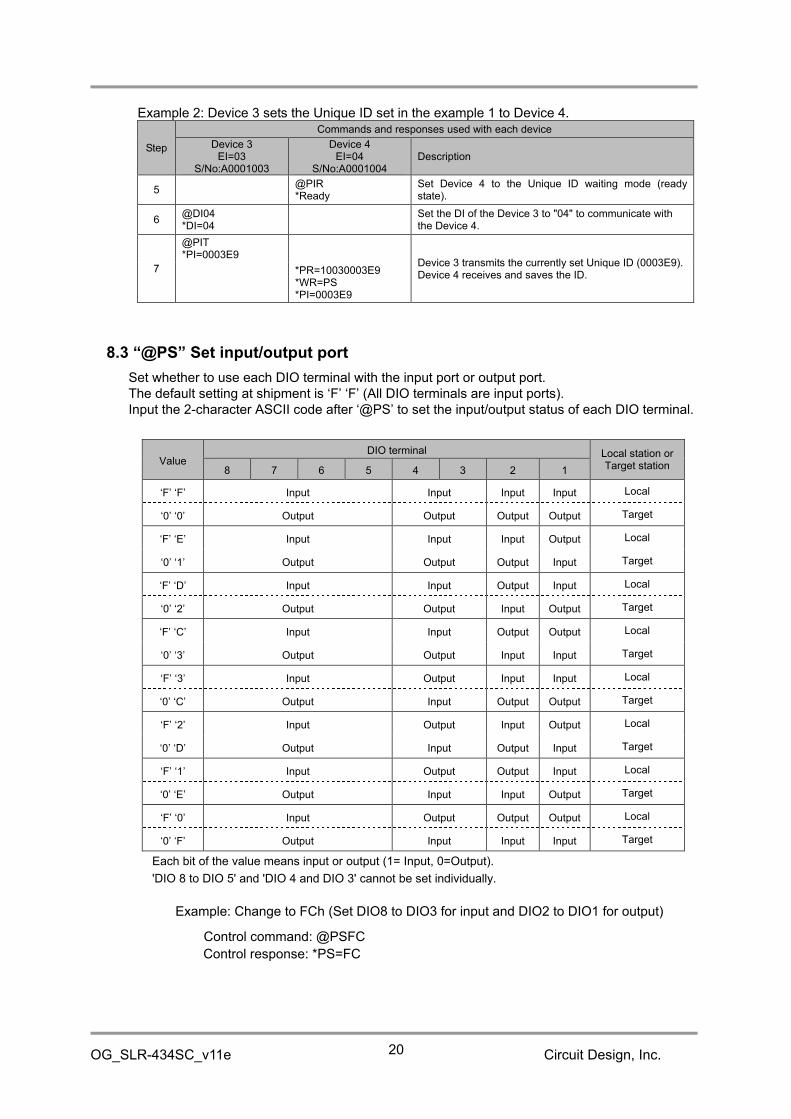
Example 2: Device 3 sets the Unique ID set in the example 1 to Device 4.
Step
Commands and responses used with each device
Device 3EI=03
S/No:A0001003
Device 4EI=04
S/No:A0001004Description
5@PIR*Ready
Set Device 4 to the Unique ID waiting mode (readystate).
6@DI04*DI=04
Set the DI of the Device 3 to "04" to communicate withthe Device 4.
7
@PIT*PI=0003E9
Device 3 transmits the currently set Unique ID (0003E9).Device 4 receives and saves the ID.*PR=10030003E9
*WR=PS*PI=0003E9
8.3 “@PS” Set input/output port
Set whether to use each DIO terminal with the input port or output port.The default setting at shipment is ‘F’ ‘F’ (All DIO terminals are input ports).Input the 2-character ASCII code after ‘@PS’ to set the input/output status of each DIO terminal.
ValueDIO terminal Local station or
Target station8 7 6 5 4 3 2 1
‘F’ ‘F’ Input Input Input Input Local
‘0’ ‘0’ Output Output Output Output Target
‘F’ ‘E’ Input Input Input Output Local
‘0’ ‘1’ Output Output Output Input Target
‘F’ ‘D’ Input Input Output Input Local
‘0’ ‘2’ Output Output Input Output Target
‘F’ ‘C’ Input Input Output Output Local
‘0’ ‘3’ Output Output Input Input Target
‘F’ ‘3’ Input Output Input Input Local
‘0’ ‘C’ Output Input Output Output Target
‘F’ ‘2’ Input Output Input Output Local
‘0’ ‘D’ Output Input Output Input Target
‘F’ ‘1’ Input Output Output Input Local
‘0’ ‘E’ Output Input Input Output Target
‘F’ ‘0’ Input Output Output Output Local
‘0’ ‘F’ Output Input Input Input Target
Each bit of the value means input or output (1= Input, 0=Output).
'DIO 8 to DIO 5' and 'DIO 4 and DIO 3' cannot be set individually.
Example: Change to FCh (Set DIO8 to DIO3 for input and DIO2 to DIO1 for output)
Control command: @PSFC
Control response: *PS=FC
OG_SLR-434SC_v11e Circuit Design, Inc.21
*Set the input/output ports of each DIO terminal for the other party in communication as a pair, in
accordance with the setting values of the input/output ports of each DIO terminal. (The status of
the terminal of the local station set in the input port is sent to the terminal of the target station set
in the output port.)
Example: Local station: @PSFC (Set DIO8 to DIO3 for input and DIO2 to DIO1 for output)
Target station: @PS03 (Set DIO8 to DIO3 for output and DIO2 to DIO1 for input)
Note:
The output status of the output ports set with the '@PS' command are the status registered with
the '@PO##/W' command or the status set with '@PO##' command.
Even after the output status is changed with the '@PT##' command or '@PM##' command
issued from the target station, the status is set back to the status set with '@PO##/W' or
'@PM##' when changing the port setting by executing the '@PS' command.
8.4 “@PO” Set and acquire the local station port status
8.4.1 Set the status of the local station port
Set the status of the port (High or Low) for each DIO terminal of the local station already set in
the output port. The status of all ports are set to Low by default.
The setting for the DIO terminal set for the input port can be either High or Low. However, when
changed to the output port, the set status is enabled (see Note of 8.4.2).
Input the 2-character ASCII code (Hex) after ‘@PO’. The values from bit 7 to bit 0 corresponds tothe status of DIO 8 to DIO1.
Example: Set DIO8 to DIO3 to the output port and DIO2 to DIO1 to the input
port with @PS03, and set the status of each output port as follows
A mode for continuously transmitting the input port status of the local station already set in the
input port to a target station.
It can be used for applications where all the DIO terminals of the local station are set to input
ports and all the DIO terminals of the target station are set to output ports, to change the status
of the corresponding DIO terminal of the target station when the status of the DIO terminals of
the local station are transmitted continuously.
The transmission interval is about 50 ms, and if a situation where the contact status sent by the
local station cannot be received by the target station continues for 1 s, the status of the DIO
terminal of the target station already set in the output port changes to the factory default Low or
the status set with @PO.
To enable this mode, set the local station to ‘@PM10'.
Be sure to set the target station to “PM00”.
Example: Control command: @PM10
Control response: *PM=10
8.6.3 Two-way continuous communication mode (FSK command mode only)
A mode for two-way continuous transmission of the input port status of the local station to the
target station, and the input port status of the target station to the local station.
For example, first set DIO terminals DIO8 to DIO5 of the local station to input port, DIO4 to DIO1
to output port, DIO terminals DIO8 to DIO5 of the target station to output port, and DIO4 to DIO1
to input port. It can be used for applications with two-way continuous communication to send the
status of the input port of the DIO terminal of the local station to the output port of the target
station, and the status of the input port of the target station to the output port of the local station.
The transmission interval is about 110 ms (the interval from transmission of the contact status of
the local station to the target station to reception of the contact status from the target station),
and if a situation where the contact status from the target station cannot be received continues
for 1 s, the status of the DIO terminal of the local station already set in the output port changes to
the factory default Low or the status set with @PO.
To enable this mode, set the local station to ‘@PM20'.
Be sure to set the target station to “PM00”.
Example: Control command: @PM20
Control response: *PM=20
8.7 “@PF” Set output port holding time
When contact information is sent in the specified times transmission mode or with the '@PT##'
command, the target station can set an output holding time to keep the received contact status.
This setting is not available when port status is set with '@PO##' and when the communication
mode is set to the one-way continuous transmission mode or the two-way continuous
transmission mode.
The setting range is from 0.1 seconds (0001) to 6553.5 seconds (FFFF).
The factory setting is 0000 (no time restriction).
OG_SLR-434SC_v11e Circuit Design, Inc.26
Input the 4-character ASCII code (Hex) after ‘@PF’ to set the output holding time.
Example) Device 1 inputs contact signal and Device 2 outputs it with the output holding time of30 seconds.
Device 1 Device 2
'@PM01'(Transmit once when changing input ports)
'@PM00' (Contact communication mode OFF)'@PF012C' (30 seconds= 012C in hex)
Note:When the status of any of the input ports changes, the status information of other ports is alsotransmitted, resulting that the status of the ports that did not change is also output as shownbelow.
8.8 Contact function responses
When communicating using the contact function, a response in the following format is output to
the UART (only when the CTS terminal is set to Low) when any contact information is received.
8.8.1 "PR" response
The response contents are represented by function codes.
Response basic format
Prefix + response name + [=] + function code + Target station ID + contact data + [CR] + [LF]
Prefix: ‘*’ = 2Ah, a code that indicates the start of the response string.
Response name: The 2 characters “PR”.
Function code: Represented by a 2-character ASCII code. See the table below.
Target station ID: Represented by a 2-character ASCII code. See "2.6 "@DI" Set Target station
ID."
Contact data: Represented by a 2-character ASCII code.
OG_SLR-434SC_v11e Circuit Design, Inc.27
Function
codeContent
Response output at:
Local station Target station
“01” A response output at the target station when the local station sends
contact information with @PT and the target station receives it.
(See "8.5.1 Acquire the status of the target station port”)
○
“02” A response output at the target station when the local station sends
contact information to set with @PT and the target station receives it.
(See “8.5.2 Set the status of the target station port”)
○
“03” A response output at the target station when the local station which is
set to the specified times transmission mode sends contact
information and the target station receives it.
(See “8.6.1 Specified times transmission mode when changing input
ports")
○
“04” A response output at the local station when it acquires the target
station port status or sets the target station port status with @PT and
receives an acknowledgement from the target station.
(See “8.5.1 Acquire the status of the target station port” and “8.5.2 Set
the status of the target station port”)
○
“05” A response output at the target station when the local station which is
set to the one-way continuous transmission mode sends contact
information and the target station receives it.
(See “8.6.2 One-way continuous transmission mode”)
○
“06” A response output at the target station when the local station which is
set to the two-way continuous communication mode sends contact
information and the target station receives it.
(See “8.6.3 Two-way continuous communication mode”)
○
“07” A response output at the local station when it is set to the two-way
continuous communication mode and receives an contact information
from the target station.
(See “8.6.3 Two-way continuous communication mode”)
○
“08” A response output at the target station when the local station which is
set to the specified times transmission mode sends contact
information to set with @PT and the target station receives it.
(See “8.5.2 Set the status of the target station port”)
○
“10” A response output at the target station when the local station sends its
own Unique ID with @PIT and the target station receives it.
(See " 8.2.4 Receive the Unique ID of the target station and set it to
the local station”)
○
OG_SLR-434SC_v11e Circuit Design, Inc.28
8.8.2 'PD' response
When transmitting in the Specified times transmission mode, a response in the following format
is output to the UART of the local station.
Response basic format
Prefix + response name + [=] + contact data + [CR] + [LF]
Prefix: ‘*’ = 2Ah, a code that indicates the start of the response string.
Response name: The 2 characters “PD”.
Contact data: The status of the input/output ports of the local station is represented by a 2-
character ASCII code.
8.8.3 Combination of the 'PR' and 'PD' responses
The table below shows the combination example of PR and PD responses, when
communicating between two SLR-434M devices using the @PT command and the contact
function communication modes.
In the following example, Device 1 is set to any of the communication modes with the @PMcommand and Device 2 is set to 'PM00' (Contact function communication OFF).
Device 1
(Local station Eqipment ID="xx", Target station ID="yy")
Device 2
(Local station Eqipment ID="yy",
Target station ID="xx")
Communication
mode settingBehavior
Response
output example
Communication
mode setting
Response output
example
@PM00
'@PT' command
transmission
(acquire the status of
target station port)*PR=04yy$$
@PM00
*PR=01xx&&
'@PT##’ command
transmission
(set the status of target
station port)
*PR=02xx##
@PM01
:
@PM05
Transmission when
changing input ports*PD=&&
*PR=03xx&&(outputs the specified
number of times)
'@PT##' command
transmission
*PR=08xx##(outputs the specified
number of times)
@PM10One-way continuous
transmission*PR=05xx&&
@PM20Two-way continuous
transmission*PR=07yy$$ *PR=06xx&&
"&&" is the status of the input/output ports of Device 1 and "$$" is the status of the input/outputports of Device 2.
OG_SLR-434SC_v11e Circuit Design, Inc.29
9. Command list
Frequency channel setting (Factory setting: "4A" 434.000 MHz)Item Command format Response format Setting value / Error description
Setting command @CH## *CH=##
"00" to "88"Setting command(save the value)
@CH##/W*WR=PS*CH=##
Acquire the setting value @CH *CH=##
Error response*ER=01 Command error*ER=02 Setting value error*ER=03 Command format error
Radio communication mode setting (Factory setting: "03" LoRa command mode)Item Command format Response format Setting value / Error description
Acquisition/setting of local station port status (Factory setting: "00")Item Command format Response format Setting value / Error description
Setting command @PO## *PO=##
"00" to "FF"Setting command(save the value)
@PO##/W*WR=PS*PO=##
Acquire the setting value @PO *PO=##
Error response*ER=01 Command error*ER=03 Command format error
Acquisition/setting of target station port statusItem Command format Response format Setting value / Error description
Setting command @PT## *PT## "00" to "FF"
Acquire the setting value @PT *PT##
Port status of the local station:"00" to "FF"
(Target port status can be acquiredwith *PR)
Error response*ER=01 Command error*ER=03 Command format error
Contact function communication mode setting (Factory setting:"00" Auto transmission OFF)Item Command format Response format Setting value / Error description
Setting command @PM## *PM=## Auto transmission OFF: "00"Specified times transmission: "01" to "05"One-way continuous transmission: "10"Two-way continuous transmission: "20"
Setting command(save the value)
@PM##/W*WR=PS*PM=##
Acquire the setting value @PM *PM=##
Error response*ER=01 Command error*ER=03 Command format error
Output port holding time setting (Factory setting: "0000" No time restriction)Item Command format Response format Setting value / Error description
Setting command @PF#### *PM=####
"0000" to "FFFF"(1 count = approx. 0.1 s)
Setting command(save the value)
@PF####/W*WR=PS*PM=####
Acquire the setting value @PF *PM=####
Error response*ER=01 Command error
*ER=03 Command format error
Unique ID setting for contact function (Factory setting: "0000" Not using Unique ID)Item Command format Response format Setting value / Error description
Setting cancel @PIC*WR=PS*PI=000000
"000000" : Not using Unique ID
Setting command @PIS*WR=PS*PI=######
"000001" to "98967F"(S/No. *0000001 to 9999999)
Set to Ready mode @PIR *PI=Ready
Transmit the setting value @PIT *PI=######
Check the setting value @PI *PI=######
Error response*ER=01 Command error*ER=03 Command format error
OG_SLR-434SC_v11e Circuit Design, Inc.32
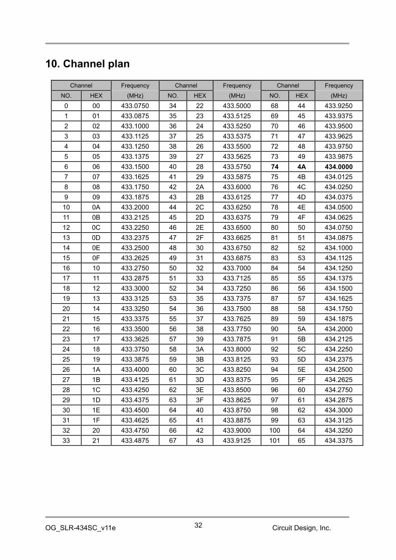
10. Channel plan
Channel Frequency Channel Frequency Channel Frequency
NO. HEX (MHz) NO. HEX (MHz) NO. HEX (MHz)
0 00 433.0750 34 22 433.5000 68 44 433.9250
1 01 433.0875 35 23 433.5125 69 45 433.9375
2 02 433.1000 36 24 433.5250 70 46 433.9500
3 03 433.1125 37 25 433.5375 71 47 433.9625
4 04 433.1250 38 26 433.5500 72 48 433.9750
5 05 433.1375 39 27 433.5625 73 49 433.9875
6 06 433.1500 40 28 433.5750 74 4A 434.0000
7 07 433.1625 41 29 433.5875 75 4B 434.0125
8 08 433.1750 42 2A 433.6000 76 4C 434.0250
9 09 433.1875 43 2B 433.6125 77 4D 434.0375
10 0A 433.2000 44 2C 433.6250 78 4E 434.0500
11 0B 433.2125 45 2D 433.6375 79 4F 434.0625
12 0C 433.2250 46 2E 433.6500 80 50 434.0750
13 0D 433.2375 47 2F 433.6625 81 51 434.0875
14 0E 433.2500 48 30 433.6750 82 52 434.1000
15 0F 433.2625 49 31 433.6875 83 53 434.1125
16 10 433.2750 50 32 433.7000 84 54 434.1250
17 11 433.2875 51 33 433.7125 85 55 434.1375
18 12 433.3000 52 34 433.7250 86 56 434.1500
19 13 433.3125 53 35 433.7375 87 57 434.1625
20 14 433.3250 54 36 433.7500 88 58 434.1750
21 15 433.3375 55 37 433.7625 89 59 434.1875
22 16 433.3500 56 38 433.7750 90 5A 434.2000
23 17 433.3625 57 39 433.7875 91 5B 434.2125
24 18 433.3750 58 3A 433.8000 92 5C 434.2250
25 19 433.3875 59 3B 433.8125 93 5D 434.2375
26 1A 433.4000 60 3C 433.8250 94 5E 434.2500
27 1B 433.4125 61 3D 433.8375 95 5F 434.2625
28 1C 433.4250 62 3E 433.8500 96 60 434.2750
29 1D 433.4375 63 3F 433.8625 97 61 434.2875
30 1E 433.4500 64 40 433.8750 98 62 434.3000
31 1F 433.4625 65 41 433.8875 99 63 434.3125
32 20 433.4750 66 42 433.9000 100 64 434.3250
33 21 433.4875 67 43 433.9125 101 65 434.3375
OG_SLR-434SC_v11e Circuit Design, Inc.33
Channel Frequency Channel Frequency Channel Frequency
NO. HEX (MHz) NO. HEX (MHz) NO. HEX (MHz)
102 66 434.3500 114 72 434.5000 126 7E 434.6500
103 67 434.3625 115 73 434.5125 127 7F 434.6625
104 68 434.3750 116 74 434.5250 128 80 434.6750
105 69 434.3875 117 75 434.5375 129 81 434.6875
106 6A 434.4000 118 76 434.5500 130 82 434.7000
107 6B 434.4125 119 77 434.5625 131 83 434.7125
108 6C 434.4250 120 78 434.5750 132 84 434.7250
109 6D 434.4375 121 79 434.5875 133 85 434.7375
110 6E 434.4500 122 7A 434.6000 134 86 434.7500
111 6F 434.4625 123 7B 434.6125 135 87 434.7625
112 70 434.4750 124 7C 434.6250 136 88 434.7750
113 71 434.4875 125 7D 434.6375
*The channel is set to No. 74 (434.000 MHz) for shipment.*If you intend to use several SLR-434M units in the same area, use a channel plan that takes intoaccount radio interference due to third-order intermodulation.
Circuit Design provides a computational tool on our website for creating channel plans that avoid
FSK command mode Tsend :≒ Roundup {(number of data bytes+7)/52,0}*(34*8/4.8+0.9)+(number of data bytes+7)*8/4.8 [ms]
FSK binary mode Tsend :≒ Roundup {number of data bytes/52,0}*(34*8/4.8+0.9)+number of data bytes*8/4.8 [ms]
The transmission time in the binary mode is shorter by 7 bytes than in the command mode. In the binarymode, transmission of data exceeding 255 bytes is possible, however we do not provide support for thetransmission time of data exceeding 255 bytes.
11.2 Data transmission time in the LoRa mode
LoRa command mode Tsend:
When the number of data bytes is 1 to 235Nsym = Roundup {(8*(number of data bytes+15)-4*SF+44)/(4*(SF-2)),0}*5Tsend = (20.25+Nsym)*Tsym [ms]
When the number of data bytes is 236 to 255Nsym = Roundup{(8*(number of data bytes+8-235)-4*SF+44)/(4*(SF-2)),0}*5Tsend = Tplmax+(20.25 + Nsym)*Tsym [ms]
LoRa binary mode Tsend :
When the number of data bytes is 1 to 242Nsym = Roundup{(8*(number of data bytes+8)-4*SF+44)/(4*(SF-2)),0}*5Tsend = (20.25+Nsym)*Tsym [ms]
When the number of data bytes is 243 to 255Nsym = Roundup {(8*(number of data bytes+1-235)-4*SF+44)/(4*(SF-2)),0}*5Tsend = Tplmax+(20.25+Nsym)*Tsym [ms]
The transmission time in the binary mode is shorter by 7 bytes than in the command mode. In the binarymode, transmission of data exceeding 255 bytes is possible, however we do not provide support for thetransmission time of data exceeding 255 bytes.
Numberof chips
SpreadingfactorSF
Tsym(ms)
Tplmax(ms)
Transmission delay(ms)
128 7 16.384 8606 22 to 1222
256 8 32.768 14426 22 to 1522
512 9 65.536 24920 22 to 3022
1024 10 131.072 43942 22 to 5222
2048 11 262.144 78709 22 to 9372
4096 12 524.288 141689 22 to 22022
OG_SLR-434SC_v11e Circuit Design, Inc.35
Important note:
The SLR-434M uses the packet communication function of the internal RF IC. The payload length of onepacket is up to 60 bytes in the FSK mode and up to 250 bytes in the LoRa mode.
When transmitting data in the command mode, since 15 bytes are added to the user data as Equipment ID,control commands and so on, the number of user data per packet is up to 45 bytes in the DSK mode andup to 235 bytes in the LoRa mode.
For example, in the FSK mode, the user data of up to 45 bytes is sent in one packet, and the data of 46 to90 bytes is sent in two packets. A 'Hi' pulse is output to the TXLED between packets.
Note: Although the data input buffer of the UART has sufficient area of 256 bytes or more, if youinput long data in the binary mode without using the RTS control signal, buffer over occursand data may be discarded. It is recommended that the data length of one transmission is e256 bytes or less.
Binarymode
Binarymode
Commandmode
Commandmode
Data [byte] Data [byte]Transmission time Transmission time
OG_SLR-434SC_v11e Circuit Design, Inc.38
Revision History
Version Date Description Remark0.91 Feb. 2017 Provisional Edition
1.0 Feb. 20181.1 Sep. 2018 Chapter 11 added
The copyright of this manual belongs to Circuit Design, Inc. Reproduction, duplication or modificationof part or all of this manual without permission is prohibited.


![Chap 3 MODULATION [Compatibility Mode]](https://static.documents.pub/doc/80x56/577cd5fc1a28ab9e789bba78/chap-3-modulation-compatibility-mode.jpg)
![A Low-Cost and Low-Power Messaging System Based on the …wireless.ictp.it/Papers/lora-communications.pdf · MobileNetwAppl modulation [9] transmission speed can traded for range.](https://static.documents.pub/doc/80x56/5eb91b97d796494c141d289b/a-low-cost-and-low-power-messaging-system-based-on-the-mobilenetwappl-modulation.jpg)


