• The cylinder head can be serviced with the engine installed in the frame.• When assembling, apply molybdenum disulfide grease or engine oil to the valve guide movable parts, valve arm and camshaft sliding surfaces for initial lubrication.
• The camshaft is lubricated by engine oil through the cylinder head engine oil passages. Clean andunclog the oil passages before assembling the cylinder head.
• After disassembly, clean the removed parts and dry them with compressed air before inspection.
• After removal, mark and arrange the removed parts in order. When assembling, install them in thereverse order of removal.
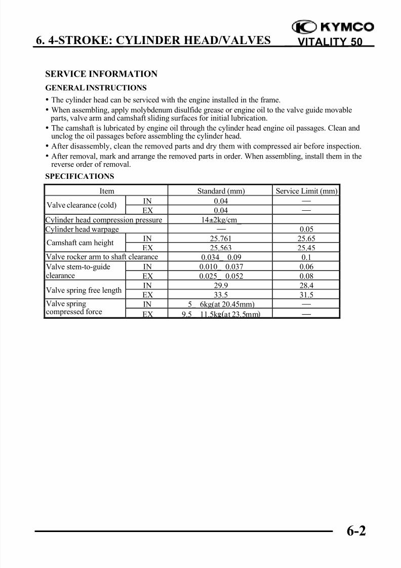
SPECIFICATIONS
Item Standard (mm) Service Limit (mm)
IN 0.04
EX 0.04
Cylinder head compression pressure 14±2kg/cm_
Cylinder head warpage 0.05
IN 25.761 25.65
EX 25.563 25.45Valve rocker arm to shaft clearance 0.034_ 0.09 0.1
Valve stem-to-guide IN 0.010_ 0.037 0.06clearance EX 0.025_ 0.052 0.08
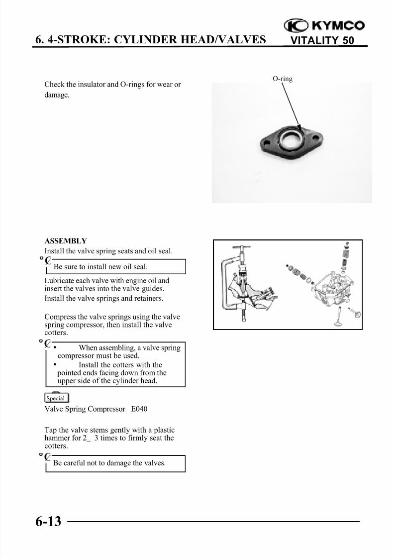
IN 29.9 28.4Valve spring free length
EX 33.5 31.5IN 5_ 6kg(at 20.45mm) Valve springcompressed force EX 9.5_ 11.5k at 23.5mm
Valve clearance (cold)
Camshaft cam height
8/3/2019 SM - Kymco Vitality 50 - Chapter 06 (4-Stroke - Cylinder Head - Valves)
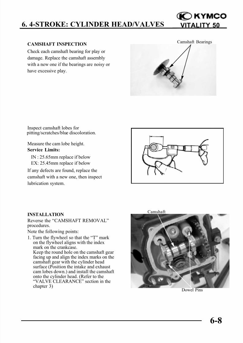
damage. Replace the camshaft assemblywith a new one if the bearings are noisy or
have excessive play.
Inspect camshaft lobes for pitting/scratches/blue discoloration.
Measure the cam lobe height.
Service Limits:
IN : 25.65mm replace if below
EX: 25.45mm replace if below
If any defects are found, replace the
camshaft with a new one, then inspect
lubrication system.
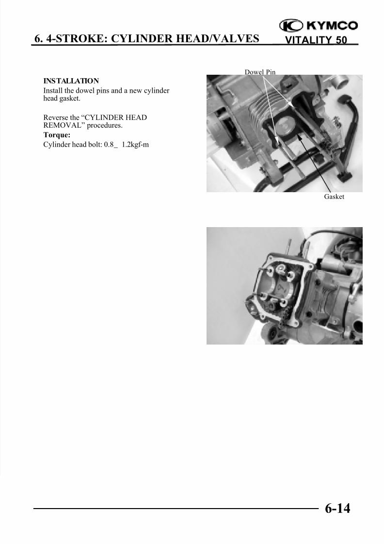
INSTALLATION
Reverse the “CAMSHAFT REMOVAL” procedures.
Note the following points:
1. Turn the flywheel so that the “T” mark on the flywheel aligns with the indexmark on the crankcase.Keep the round hole on the camshaft gear facing up and align the index marks on thecamshaft gear with the cylinder headsurface (Position the intake and exhaustcam lobes down.) and install the camshaftonto the cylinder head. (Refer to the“VALVE CLEARANCE” section in thechapter 3)
Camshaft Bearings
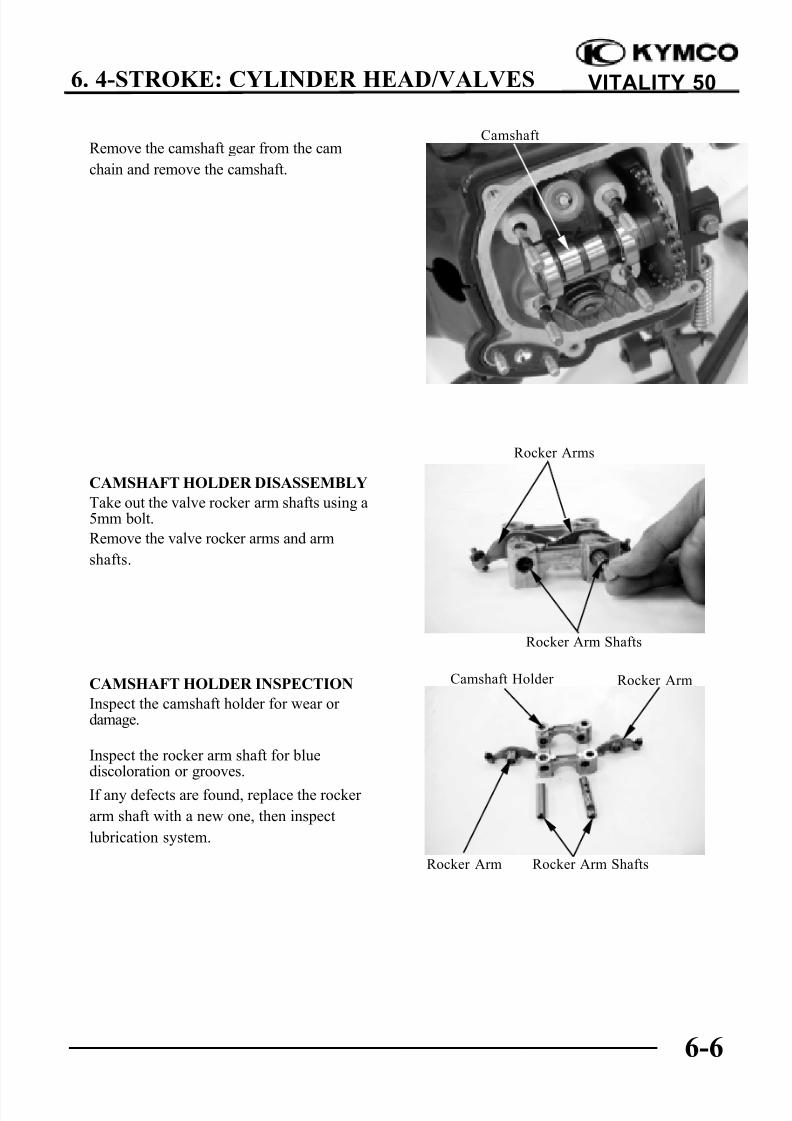
Camshaft
Dowel Pins
8/3/2019 SM - Kymco Vitality 50 - Chapter 06 (4-Stroke - Cylinder Head - Valves)
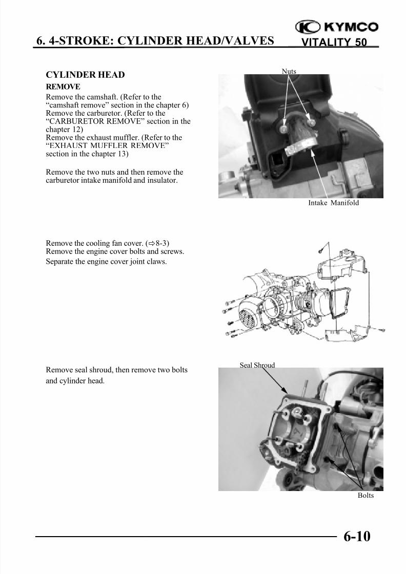
Remove the camshaft. (Refer to the“camshaft remove” section in the chapter 6)Remove the carburetor. (Refer to the“CARBURETOR REMOVE” section in thechapter 12)Remove the exhaust muffler. (Refer to the“EXHAUST MUFFLER REMOVE”section in the chapter 13)
Remove the two nuts and then remove thecarburetor intake manifold and insulator.
Remove the cooling fan cover. (8-3)Remove the engine cover bolts and screws.
Separate the engine cover joint claws.
Remove seal shroud, then remove two bolts
and cylinder head.
Nuts
Intake Manifold
Seal Shroud
Bolts
8/3/2019 SM - Kymco Vitality 50 - Chapter 06 (4-Stroke - Cylinder Head - Valves)
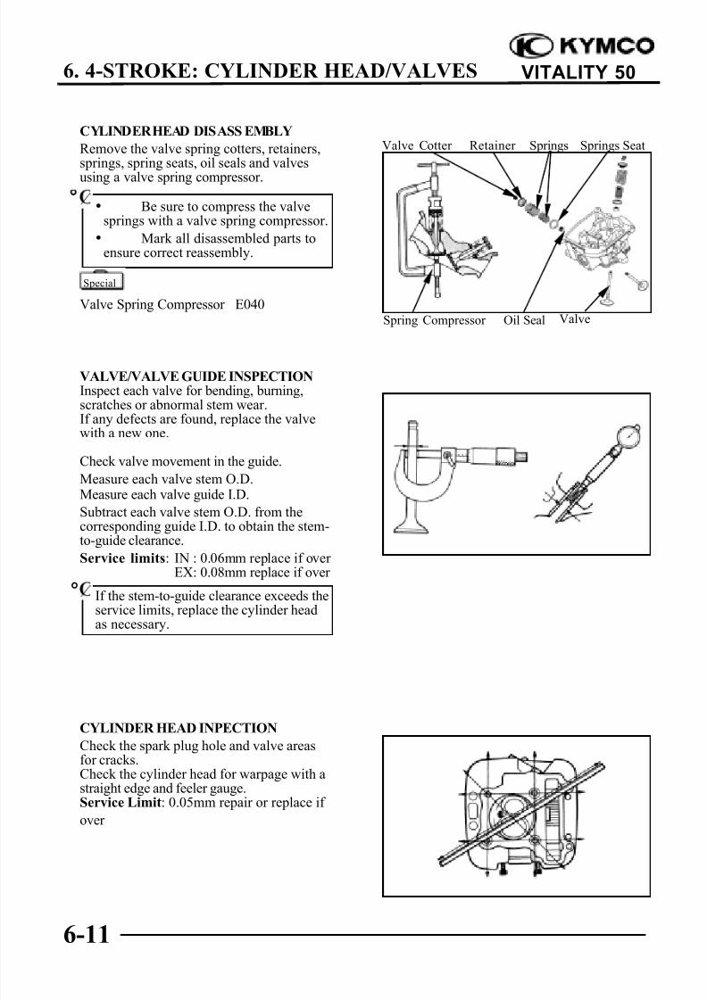
Remove the valve spring cotters, retainers,springs, spring seats, oil seals and valves
using a valve spring compressor.
Valve Spring Compressor E040
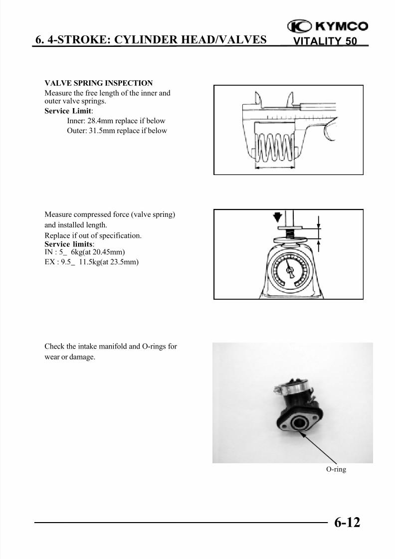
VALVE/VALVE GUIDE INSPECTIONInspect each valve for bending, burning,scratches or abnormal stem wear.If any defects are found, replace the valvewith a new one.
Check valve movement in the guide.
Measure each valve stem O.D.Measure each valve guide I.D.
Subtract each valve stem O.D. from the
corresponding guide I.D. to obtain the stem-to-guide clearance.
Service limits: IN : 0.06mm replace if over EX: 0.08mm replace if over
CYLINDER HEAD INPECTION
Check the spark plug hole and valve areasfor cracks.Check the cylinder head for warpage with astraight edge and feeler gauge.Service Limit: 0.05mm repair or replace if
over
Valve Cotter Retainer Springs Springs Seat
Oil Seal ValveSpring Compressor
• Be sure to compress the valvesprings with a valve spring compressor.
• Mark all disassembled parts toensure correct reassembly.
Special
If the stem-to-guide clearance exceeds theservice limits, replace the cylinder headas necessary.
°
8/3/2019 SM - Kymco Vitality 50 - Chapter 06 (4-Stroke - Cylinder Head - Valves)