Grand Total (mA) 24vdc Hold Grand Total (VA) Hold Feeder 120 Vac (VA) Hold Max Rated Power (VA) Hold Heat Dissipation (W) Hold Field cables Bottom Communication cables Bottom Power supply cables Bottom PC: None Printer: None Feeder voltage 120Vac Feeder frequency 60HZ PSU feeder per system 2 Fan feeder 0 Misc. feeders: 0 Total feeders 2 Cabinet Quantity System Syst/FTA Marshallin g Cabinets Complexed Cabinets not Complexed SIS_SM_01 1 0 0 0 Busbar mounted on Revision: A Date: 06/18/2012 SM System Information SIS_SM_01 SIS_SM_01 System Type Power and Heat Summary 2oo4D with redundant I/O X 2oo4D with single I/O 2oo4D with redundant and single I/O Cable Entry (Top, Bottom, or Both) AC Power Feeders Accessories Ethernet Cables to Server Supplied By Quantity Honeywel 2 sets System Cabinets Special Wiring Notes: 120Vac/24Vdc Power Distribution (Typical) Field Safety Manager cabinet Distribu tion termina ls Power supply unit AC Pre fabricate d power cables I/O chassis L Feeder 1 N L + N DC - I/O chassis I/O chassis L Feeder 2 N AC L + N DC - Fused termin als I/O chassis Internal use Internal use L Fee der 3 Main circuit breaker
Transcript
Grand Total (mA) 24vdc HoldGrand Total (VA) HoldFeeder 120 Vac (VA) HoldMax Rated Power (VA) HoldHeat Dissipation (W) HoldField cables Bottom
Communication cables BottomPower supply cables Bottom
PC: NonePrinter: NoneFeeder voltage 120Vac
Feeder frequency 60HZPSU feeder per system 2Fan feeder 0Misc. feeders: 0Total feeders 2
Cabinet QuantitySystem Syst/FTA Marshalling Cabinets Complexed Cabinets not Complexed
SIS_SM_01 1 0 0 0
Revision: A Date: 06/18/2012
SM System Information
SIS_SM_01 SIS_SM_01System Type Power and Heat Summary
2oo4D with redundant I/O X2oo4D with single I/O2oo4D with redundant and single I/O
Cable Entry (Top, Bottom, or Both)
AC Power FeedersAccessories
Ethernet Cables to ServerSupplied By QuantityHoneywell 2 sets
System Cabinets
Special Wiring Notes:
120Vac/24Vdc Power Distribution (Typical)
Field Safety Manager cabinet
Distribution terminals
Power supply unit
AC
Pre fabricated power cables
I/O chassis
L Feeder 1
N
L +
N DC -I/O chassis
I/O chassis
L Feeder 2
N
ACL +
N DC -
Fused terminals
I/O chassis
Internal use
Internal use
L Feeder 3
Main circuit breaker
Lamp with outlet socket
L
Circuit breakerRelay SOV, IRP& LED outputs
Non UPS N N Relay SOV, IRP& LED outputs
Cabinet Type IPSystem 20FTA 20Marshalling 20
Revision: A Date: 06/18/2012
SM System Compliance
SIS_SM_01 SIS_SM_01System Compliance Sticker Igress Protection Class
Cabinet Type StickerSystem NoneFTA NoneMarshalling None
Environmental ConditionsOperating Temperature –5°C to 70°C (14°F to 158°F), ambient (1)Storage Temperature –25°C to +80°C (–13°F to +176°F)Relative Humidity 5% to 95%, non-condensingVibration, Sinusoidal IEC 60068-2-6; 1 G at 57 Hz to 150 Hz; 10 Hz toShock IEC 60068-2-27; 15 G for 11 ms, 3 axesElectrostatic Discharge IEC 61000-4-2, Level 4 (15 kV)Conducted Susceptibility IEC 61000-4-4, Level 3, Fast Transient/Burst IECRated Susceptibility IEC 61000-4-3, Level 3
Conducted Emissions Measured per CISPR 11 & CISPR 22
EMC/EMI RequirementsThe SM System cabinets are designed and constructed in accordance with EMC and Low Voltage Guidelines for Safety Manager; document MTTSP-0000-321000.
Codes and StandardsInternational Electronical Commission (IEC)The design and development of Safety Manager are compliant with IEC61508 (as certified by TUV).
TUV (Germany)Certified to fulfill the requirements of SIL3 safety equipment as defined in the following documents: IEC61508, IEC60664-3, EN50156, EN54-2, EN50178, IEC60068, IEC61131-2, IEC61131-3, and IEC60204.
Instrument Society of America (ISA)Certified to fulfill the requirements laid down in ANSI/ISA S84.01.
CE ComplianceCompliance with CE directives 89/336/EEC (EMC) and 73/23/EEC (Low voltage), 89/392/EEC (Machine Safety).
European Committee for StandardizationCEN, CENELEC
Lloyds Register of ShippingTest specification nr 1 (LRS), 96/98/EEC (EEC Marine directive)
Canadian Standards Associations (CSA)Complies with the requirements of the following standards:· CSA Standard C22.2 No. 0-M982 General Requirements – Canadian Electrical code, Part-II.· CSA Standard C22.2 No. 142-M1987 for Process Control equipment.
Underwriters Laboratories (UL)Certified to fulfill the requirements of UL 508, UL 991, UL 1998 and ANSI/ISA S84.01.
Factory Mutual (FM)Certified to fulfill the requirements of FM 3611 and FM 3600 (non-incentive field wiring circuits for selected modules and installation in Class 1 Div 2 environments).
Revision: A Date: 06/18/2012
SM System Compliance
Codes and StandardsStandard Title Remarks
IEC61508 (S84.01) Functional safety of electrical/electronic/programmableelectronics (E/E/PE) safety-related systems.
DIN V 0801 (1/90) and Amendment A(10/94)
Principles of computers in safety-related systems. Microprocessor-based safety systems.
VDE 0116 (10/89) Electrical equipment of furnaces.
EN 54 part 2 (01/90) Components of automatic fire detection systems,introduction.
EN 50081-2-1994 Electromagnetic compatibility – Generic emissionstandard, Part 2: Industrial environment.
EN 50082-2-1995 Electromagnetic compatibility – Generic immunitystandard, Part 2: Industrial environment.
IEC 61010-1-1993 Safety requirement for Electrical Equipment forMeasurement, Control and Laboratory use, Part 1: General requirement.
IEC 61131-2-1994 Programmable controllers, Part 2: Equipment requirement
UL 1998 Sadfetty rtelated software, first edition. Underwriters Laboratories.
UL 508 Industrial control equipment, sixteenth edition. Underwriters Laboratories.
UL 991 Test for safety related controls employing solid-state Underwriters Laboratories.
FM 3600, FM 3611 Class I, Division2, Groups A, B, C & D, Class II, Division 2, Groups F & G.
Electrical equipment for use in,· Class I, Division 2,· Class II, Division 2 and· Class III, Division 1 and 2, hazardous locations.
Factory Mutual Research. Applies to the field wiringcircuits of the following modules:SDI-1624, SAI-0410, SAI-1620m, SDIL-1608 and SAO-0220m, and installation of the controller in these environments.
CSA C22.2 Process control equipment. Industrial products. Canadian Standard Association No. 142 (R1993).
IEC 60068-1 Basic environment testing procedure.
IEC 60068-2-1 Cold test. 0oC (32 oF); 16 hours; system in operation, reducedpower supply voltage: (-15%): U=20.4 Vdc or (-10%): U=198 Vac.
IEC 60068-2-1 Cold test. -10oC (14 oF); 16 hours; system in operation.
IEC 60068-2-2 Dry heat test. Up to 65oC (149 oF); 16 hours; system in operation;increased power supply voltage: (-15%): U=27.6 Vdc or (-10%): U=242 Vac.
IEC 60068-2-3 Test Ca: damp heat, steady state. 21 days at +40oC (104 oF), 93% relative humidity;function test after cooling.
IEC 60068-2-3 Test Ca: damp heat, steady state. 96 hours at +40oC (104 oF), 93% relative humidity;system in operation.
IEC 60068-2-14 Test Na: change of temperature – withstand test. -25oC - +55oC (-13 oF – 131 oF), 12 hours, 95% relativehumidity, recovery time: max 2 hours.
IEC 60068-2-30 Test Db variant 2: cyclic damp heat test. +25oC - +55oC (-77 oF – 131 oF), 48 hours, 80-100%relative humidity, recovery time: 1 - 2 hours.
IEC 60068-2-6 Environmental testing – Part 2: Tests – Test Fc: vibration(sinusoidal).
Excitation: sine-shaped with sliding frequency;Frequency range: 10 -150 Hz. Loads:· 10-57 Hz; 0.075 mm· 57-150Hz, 1G.Duration: 10 cycles (20 sweeps) per axis. No. of axes: 3 (x, y, z). Traverse rate: 1 oct/min in operation.
IEC 60068-2-27 Environmental testing – Part 2: Tests – Test. Ea: shock. Half sine shock. 2 shocks per axes (6 in total). 2 shocksper axes (6 in total). Maximum acceleration: 15 G. Shock duration: 11 ms. Safety Manager in operation.
Honeywell
Input modulesModulesQuantity
SignalsSIF
ModulesQuantity
SignalsSIF
Single RedundantFC-SAI-0410 AIFC-SAI-1620m AI HDFC-SDI-1624 DI 24 VDC FC-SDI-1648 DI 48 VDC FC-SDIL-1608 DI LM BSAI-04x AI Prog.FC-TSDI-1624 DI 24VDC FC-TSAI-1620m AI FTAFC-TSFIRE-1624 Fire FTAFC-TSDI-16115 115 V
MTTF dangerous: 123287 years ~ 99.9996 % PFDAVG = 4.06E-06MTTF safe: 35.6 years ~ 99.9923 % SFF = 99.9964 %
HoneywellSM Software/Applications Configuration
SM Safety Builder Application NamesPlant Name System Name System Number
BP Pascagoula SIS SIS_SM_01 1
SOE Application NamesName
NA
SM IP Address and Subnet (Experion)System CP1 CP2
IP Address hold holdSubnet Mask hold hold
Default Gateway hold hold
SM IP Address and Subnet (Maintenance Network)System CP1 CP2
IP Address hold holdSubnet Mask hold hold
Default Gateway hold hold
Safety ClassificationSIL Level
3
Diagnostic Test Interval (DTI) DTI
1
Maximum Repair TimeRepair Time
Disabled
This parameter specifies the safety requirement class for the overall system. It must be set to the requirement classification of the process parts (loops) with the highest safety demand. The SM Configuration can be defined as SIL 1 / 2/ or 3.
The DTI is the process diagnostic time (= fault tolerant time of the process) which is the maximum time period allowed to the system to test and detect all system hardware. This is the maximum times allowed to do all tests, re-tests and assure safety reaction if faults are detected. In general the SM Controller will execute all tests every processor cycle. Some tests that may require more time, e.g. testing of analog channels, may be split over various cycles, to keep the processor cycle time as low as possible.
During normal operation, each CPU of SM performs self-tests and tests the allocated IO modules. If a fault is detected during the tests, the CPU reports the failure and takes action to guarantee a safe operational state. If possible, the fault will be isolated and CPU operation continues. If the continuation of Safe operations cannot be guaranteed, the CPU stops. Certain failure types can be isolated, but safe operations can then only be guaranteed as long as no additional faults occur, which, in correlation with the first failure, may lead to unsafe operation. Therefore, when continuing operation, there is a certain risk of such an additional correlating faults occurring. The longer SM operates, the larger this risk becomes. To keep the risk within acceptable limits, a time interval can be defined: the maximum repair time, which reflects the maximum period of time the CPU is allowed to operate after the first failure occurrence. When the maximum repair time expires, the CPU shuts down.The maximum repair time can be defined between 0 and 2047 hours, or can be completely deactivated. In the latter case, organizational measures must be defined to ensure correct action on SM failure reports.
HoneywellRevision: A Date: 06/18/2012
SIF Loop Arrangement
A SIF consists of multiple components that in many cases are not all within the Honeywell project scope. The following model is used to define the SIS system architecture and typical loops that can be used to achieve the required SIL:
SensorConfiguration
Logic System and I/O
Final ElementConfiguration
The following table represents the typical arrangements that can be used in the system design in respect to the requested SIL.
Single Switch 1oo1 SIL 1,2 Fault Tolerance=0Single Transmitter 1oo1 SIL 1,2 Fault tolerance=0Two Switches 1oo2 SIL 1,2,3 Fault tolerance=1Two Switches 2oo2 SIL 1,2 Fault tolerance=0 Not recommended.Two Transmitters 1oo2 SIL 1,2,3 Fault tolerance=1Two Transmitters 2oo2 SIL 1,2 Fault tolerance=0 Not recommended.Single Switch andSingle Transmitter 1oo2 SIL 1,2,3 Fault tolerance=1 API RP14C compliant.
Single Switch andSingle Transmitter 2oo2 SIL 1,2 Fault tolerance=0 Not recommended.
Three Transmitters 1oo3 SIL 1,2,3 Fault tolerance=2Three Transmitters 2oo3 SIL 1,2,3 Fault tolerance=1Three Transmitters 3oo3 SIL 1,2 Fault tolerance=0 Not recommended.Single Solenoid 1oo1 SIL 1,2 Fault tolerance=0Two Solenoids 1oo2 SIL 1,2,3 Fault tolerance=1Two Solenoids 2oo2 SIL 1 Fault tolerance=0 Not recommended.
The table above assumes that the client has selected the following devices:* Switches with a safe failure fraction of between 60 and 90%.* Transmitters with a safe failure fraction of less than 60%.* Solenoids with a safe failure fraction of between 60 and 90%.
Legend:DI = Digital Input DO = Digital Output AO = Analog Output AI = Analog InputFS = Fail SafeNFS = Not Fail Safe IP = Internal Power EP = External Power CL = Current Limited LM = Loop MonitoringSIC = System Interface CableFTA = Field Termination AssemblyVF = Voltage Free contacts from relay* = 2 FS-TPSU-2430 per pair of FS-TSAI-1620m for redundant I/O racks;1 FS-TPSU-2430 per pair of FS-TSAI-1620m for single I/O racks
USP-002536 - SMSDM Rev A Page 18 of 32 System Cab IO
HoneywellRevision: A Date: 06/18/2012
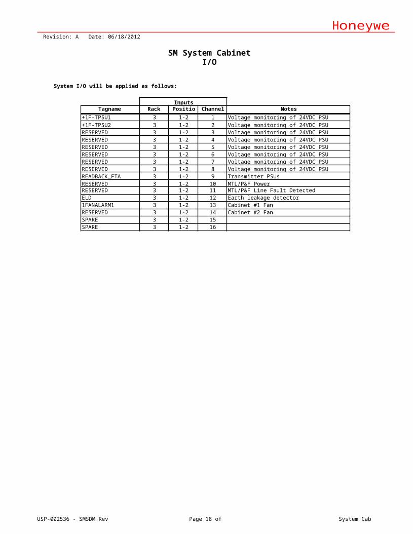
SM System Cabinet I/O
System I/O will be applied as follows:
InputsTagname Rack Position Channel Notes
+1F-TPSU1 3 1-2 1 Voltage monitoring of 24VDC PSU+1F-TPSU2 3 1-2 2 Voltage monitoring of 24VDC PSURESERVED 3 1-2 3 Voltage monitoring of 24VDC PSURESERVED 3 1-2 4 Voltage monitoring of 24VDC PSURESERVED 3 1-2 5 Voltage monitoring of 24VDC PSURESERVED 3 1-2 6 Voltage monitoring of 24VDC PSURESERVED 3 1-2 7 Voltage monitoring of 24VDC PSURESERVED 3 1-2 8 Voltage monitoring of 24VDC PSUREADBACK_FTA 3 1-2 9 Transmitter PSUsRESERVED 3 1-2 10 MTL/P&F PowerRESERVED 3 1-2 11 MTL/P&F Line Fault DetectedELD 3 1-2 12 Earth leakage detector1FANALARM1 3 1-2 13 Cabinet #1 FanRESERVED 3 1-2 14 Cabinet #2 FanSPARE 3 1-2 15SPARE 3 1-2 16
USP-002536 - SMSDM Rev A Page 19 of 32 Cabinet Tags
SIS-SM-015 mm
20 mm
5 mm
120 mm
SIS-SM-015 mm
20 mm
5 mm
120 mm
HoneywellRevision: A Date: 06/18/2012
SM Cabinet Tags
Cabinet #1, Front
30 mm
Cabinet #1, Rear
30 mm
1. Front and back door tagging is three layer (red, white, red) plastic. Tags will be centered 250 mm from the top of the door.
USP-002536 - SMSDM Rev A Page 20 of 32 BOM
HoneywellRevision: A Date: 06/18/2012
SM Bill of Material
Qty ItemID Description Category1 FC-FANWR-24R 24VDC FAN UNIT WITH READBACK CC SM Cabinet1 FS-BCU-0016 RITTAL TS8808211 FDL/RDR/PL/SW RAL7035 SM Cabinet3 FS-BLIND-CHAS4HE COVERPLATE FOR 19 INCH CHASSIS 4HE SM Cabinet9 MOB1(4603076) MOB1 MOUNTING CHASSIS FTA, TERMINALS SM Cabinet2 FC-PSU-240516 POWER SUPPLY UNIT 24/5+F159VDC, 16A CC SM Central Parts2 FC-QPP-0002 ENHANCED PERFORMANCE QUAD PROCESSOR PACK SM Central Parts2 FC-USI-0001 UNIVERSAL SAFETY INTERFACE CC SM Central Parts1 Fc-BKM-0001 BATTERY AND KEY SWITCH MODULE CC SM Central Parts2 FS-BLIND-COM DUMMY COM MODULE FOR NOT-USED SLOTS SM Central Parts1 FS-CPCHAS-0001 CHASSIS FOR CONTROL PROCESSOR SM Central Parts2 FC-DCOM-232/485 COMMUNICATION INTERFACE FTA RS232/485 CC SM Communications2 FS-CCI-HSE-02 SET ETHERNET CABLES INTERNAL, SFTP,1Y/1G SM Communications4 FS-CCI-UNI-02 COMM.CABLE INTERNAL BETWEEN DCOM-CPCHAS SM Communications2 MTL24571 MTL DIN RAIL MOUNT PROTECTION MODULE SM Communications1 SDW-550EC HIGH SPEED ETHERNET SWITCH SDW-550-EC SM Communications
34 FS-SICC-0001/L3 SYSTEM INTERCONNECTION CABLE TERM.ON FTA SM I/O Cabling8 FC-SAI-1620m SAFE HDAI MODULE 24 VDC 16CH CC SM I/O Modules
14 FC-SAO-0220M SAFE AO MODULE 0(4)-20MA 2CH CC SM I/O Modules18 FC-SDI-1624 SAFE DIGITAL INPUT MODULE 24VDC 16CH CC SM I/O Modules28 FC-SDO-0824 SAFE DO MODULE 24VDC 0.55A 8CH CC SM I/O Modules2 FC-PDB-0824 POWER DISTR.BOARD 8CH.24VDC 2A CC SM Power2 FC-PSU-UNI2450U FC-PSU-UNI2450U V1.0. SM Power1 FS-MB-0001 POWER BUSBAR MAX.200A 24/48/110VDC,150CM SM Power0 FS-PDB-CPX05 POWER DISTR.BOARD CONTROLLER CAB 5VDC WD SM Power1 FS-PDC-CPSET POWER DISTRIBUTION CABLE SET CPCHAS-0001 SM Power0 FS-PDC-CPX05 POWER DISTR.CABLE PDB-CPX05 5VDC WD SM Power7 FS-PDC-FTA24 POWER DISTR.CABLE PDB-0824 TO FTA 24V 2A SM Power5 FS-PDC-IOR05 POWER DISTR.CABLE IOCHAS-0001R 5VDC WD SM Power5 FS-PDC-IOSET POWER DISTRIBUTION CABLE SET IOCHAS-0001 SM Power0 FS-PDC-IOX05-1 POWER DISTR.CABLE 1ST EXT.CAB PDB-IOX05 SM Power2 FS-PDC-MB24-1 POWER DISTR.CABLE MB-0001 TO PDB-0824 SM Power0 FS-PDC-MB24-2 POWER DISTR.CABLE MB-0001 TO PDB-0824 SM Power1 FC-TERM-0002 BUS TERMINATOR FOR REDUNDANT I/O CC SM Racks
26 FS-BLIND-IO BLIND FRONT FOR NOT USED SLOTS IOCHAS SM Racks2 FS-IOBUS-CPIO I/O BUS CPCHAS TO IOCHAS SM Racks0 FS-IOBUS-CPIOX I/O BUS IOBUS-CPX TO IOCHAS IN EXT.IOCAB SM Racks0 FS-IOBUS-CPX-1 I/O BUS FROM CPCHAS TO 1ST EXT.IOCABINET SM Racks5 FC-IOCHAS-0001R CHASSIS FOR REDUNDANT I/O MODULES CC SM Racks1 FS-SMSB-ST-145 SAFETY BUILDER R145 SOFTWARE BASIC+KB145 SM Software1 10310/1/1CC EARTH LEAKAGE DETECTOR (RAIL MOUNTED) CC SM Special Modules4 FC-TPSU-2430 24 VDC TO 30 VDC/1 A CONVERTER CC SM Terminations4 FC-TSAI-1620m SAFE AI FTA 0(4)-20MA 16CH CC SM Terminations7 FC-TSAO-0220M SAFE AO FTA 0(4)-20MA 2CH CC SM Terminations2 FC-TSDI-16115 SAFE ACTIVE/PASSIVE DI FTA 115V, 16CH CC SM Terminations7 FC-TSDI-1624 SAFE DI FTA 24 VDC, 16 CH CC SM Terminations4 FC-TSRO-08UNI DO(RELAY) FTA SIL3 COMMON POWER 8CH CC SM Terminations3 FC-TRO-0824 DO(RELAY) FTA 8CH CC SM Terminations4 FC-TSDO-0824 SAFE DO FTA 24 VDC, 8CH CC SM Terminations3 FC-TSRO-0824 DO(RELAY) FTA FOR SIL3 APPL. 8CH CC SM Terminations
USP-002536 - SMSDM Rev A Page 21 of 32 Documentation
HoneywellRevision: A Date: 06/18/2012
SM System Documentation
The following quantities of documentation will be issued “for approval” and “as shipped” as noted:
DOCUMENT FOR APPROVAL FAT/SAT AS BUILT FORMATCabinet layout sketch 1 1 1 *.XLSRack layout sketch 1 1 1 *.XLSCommunication layout sketch 1 1 1 *.XLSFTA layout sketch 1 1 1 *.XLSCabinet bill of materials 1 1 1 *.XLSStandard SM System Drawing Package 1 1 *.DWGPower consumption/heat dissipation 1 1 *.PDFFactory Test 1 1 *.PDFFactory/Site Acceptance Test 1 1 *.PDF
Notes:1. System Drawing will be available at FAT/SAT for customer comments and markups2. Units of measurement: inches, feet, pounds.3. Language: English4. Since the SDM (System Design Manual) goes through the approval process from the customer, the detailed
drawings mentioned above will be approved by Honeywell unless it is specifically required by the customer and as a result will have a schedule impact.
5. Final system drawing package will be issued As-Built per contractual requirements
Title block contents: Customer: AFE: Project: Location: SAP#:
USP-002536 - SMSDM Rev A Page 22 of 32 Cab 1 - Front View
Coverplate
Control Processors
I/O RACKRedundant
I/O RACKRedundant
I/O RACKRedundant
I/O RACKRedundant
I/O RACKRedundant
Coverplate
Coverplate
Coverplate
+1F- TPSU2
HoneywellRevision: A Date: 06/18/2012
SM 2oo4DCabinet #1 Front View
EthernetDcom Modules
Dcom232/485 Dcom
232/485
+1F- TPSU1
Pivot
Notes:
Front View Without Door Front View Without Door & SwingframeSwingframe Cabinet
TS8808211 (800mm x 800mm) (31.5" x 31.5")
1. Door has pushbutton handle. Key lock.
USP-002536 - SMSDM Rev A Page 23 of 32 Cab 1 - Rear & Top View
2
HoneywellRevision: A Date: 06/18/2012
SM 2oo4DCabinet #1 Rear and Top View
1
FTA ROWA B C
9 9 9
6 7
2 34 4
8 5 10
19 " racks
Front Door
Top Half View With Door
Legend:
1. 24 VDC enclosure cooling fans2. Comm converters3. COM Switches4. 120vac/24 VDC Power Supplies5. Swingframe6. Master reference bar7. Safety earth bar8. System alarms FTA9. FTAs with integral SIC and field cable duct10. 120vac Feeder Terminals
9 97 6
Rear ViewSwingframe Cabinet
USP-002536 - SMSDM Rev A Page 24 of 32 Central Part with IO
Wire Device 1 Device 2 Term 2 Size Color Wire Tag1 Hold 1R-XFTA0402 43 16 Bk Hold / 1R-XFTA0402-432 Hold 1R-XFTA0402 41 16 Bk Hold / 1R-XFTA0402-413 Hold 1R-XFTA0402 53 16 Bk Hold / 1R-XFTA0402-534 Hold 1R-XFTA0402 51 16 Bk Hold / 1R-XFTA0402-515 Hold 1R-XFTA0505 11 16 Bk Hold / 1R-XFTA0505-116 Hold 1R-XFTA0505 12 16 Wh Hold / 1R-XFTA0505-12
Note:Switch contact will be open in the normal position and closed in the enable/open position.
Hold
USP-002536 - SMSDM Rev A Page 31 of 32 1F-XTB0605 (24Vdc Power)
PDC
-FTA
24
HoneywellHoneywell Process Solutions - Safety DisciplineRevision: A Date: 06/18/2012
SM 2oo4D with Redundant I/O24Vdc Power Distribution for DCV6000
+1F-XTB0605
PDB-0824
+Out1
-
+1F-FPDB2
+1F-FPDB2-OUT5
+1F-XTB0605
Rd Bk
250 mA 1
250 mA 2
+Out2
-
+
250 mA 3
Bk Wh250 mA 4
250 mA 5
Out3
Out4
Out5
Out6
Out7
-
+
-
+ Rd
- Bk
+
-
+
250 mA 6
Hold
Wiring by Others
-
+Out8
-
All Fused 2A Max
Note: PDC-FTA24 are pre-made power cables designed to connect to the PDB-0824 power distribution boards.
HoneywellHoneywell Process Solutions - Safety DisciplineRevision: A Date: 06/18/2012
SM 2oo4D with Redundant I/O
USP-002536 - SMSDM Rev A Page 32 of 32 1F-XTB0605 (24Vdc Power)
Notes for Marshalling and Non-SM Equipment Installation
Activities1 Mount and wire 2 switches and 1 light2 Mount and wire 1 24Vdc Power Distribution terminal strip3 6 single wire/jumpers (bypass switches)4 1 PDC-FTA24 cables (from +1F-FPBD2 to +1F-XTB0605)
1 Switch w/ nameplate1 Switch w/ nameplate1 Light w/ nameplate6 Fused Term1 End Cover2 End Clamp1 Marker Carrier
As Req'd Strip Markers Model as required6 Wire Single Conductor AWG#16 Note 2
Notes1 Terminal count is approximate.2 Pin ferrules required (thru barrel crimp, not end crimp) (Weidmuller)3 HGIC to confirm all terminal types and model numbers and adjusts as required.