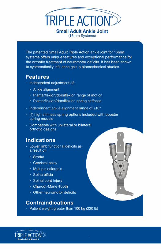
The patented Small Adult Triple Action ankle joint for 16mm systems offers unique features and exceptional performance for the orthotic treatment of neuromotor deficits. It has been shown to systematically influence gait in biomechanical studies.
- Patient weight greater than 100 kg (220 lb)Contraindications
- Independent ankle alignment range of ±10° - (4) high stiffness spring options included with booster
spring models - Compatible with unilateral or bilateral
orthotic designs
Features - Independent adjustment of:
• Ankle alignment• Plantarflexion/dorsiflexion range of motion• Plantarflexion/dorsiflexion spring stiffness
®
Small Adult Ankle Joint1.
*The Booster Spring Unit cannot be removed from the Triple Action component housing. Doing so will destroy the Booster and void the product warranty.
ModelsBooster
ConfigurationEarly Stance
PhaseLate Stance
Phase Leg Side Order No.
NORMAL
NORMALABNORMAL
3B76-A0*
NORMAL ABNORMAL
ABNORMAL
Right
Left
Lateral
Medial3B76-A1*
Right
Left Lateral
Medial
Right
Left
Lateral
Medial
Right
Left Lateral
Medial
*Only available direct from Becker Orthopedic in some countries
3B76-A2*
3B76-A2*
3B76-A1*
3B76-A3
Either
Either
Adjustment Wrenches (included)
None
PF
DF
PF & DF
Note: Right lateral component shown
®
Small Adult Ankle Joint2.
Options & Accessories
The fabrication tool kit includes fabrication dummies, alignment axis, attachment hardware and wrenches.
Fabrication Tool Kit (Model 3B00-FTK)
Lateral Stirrup(Models 3B76-LATR-1 &
3B76-LATL-1)
Medial Stirrup(Models 3B76-MEDR-1 &
3B76-MEDL-1)
Thermoplastic unilateral AFO’s require Camber Axis Triple Action Companion Joint, or other free motion ankle joint.
Y Stirrup(Model 3B76-Y-1)
Universal Rivet Stirrup(Model 3B76-R-1)
Camber Axis Triple Action Companion Joint
(Model 751-ATA)
®
Small Adult Ankle Joint3.
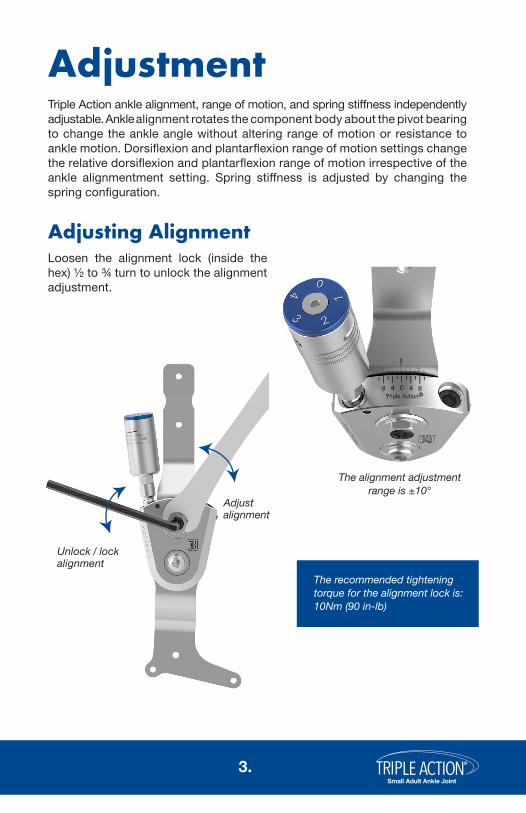
AdjustmentTriple Action ankle alignment, range of motion, and spring stiffness independently adjustable. Ankle alignment rotates the component body about the pivot bearing to change the ankle angle without altering range of motion or resistance to ankle motion. Dorsiflexion and plantarflexion range of motion settings change the relative dorsiflexion and plantarflexion range of motion irrespective of the ankle alignmentment setting. Spring stiffness is adjusted by changing the spring configuration.
Loosen the alignment lock (inside the hex) ½ to ¾ turn to unlock the alignment adjustment.
The alignment adjustment range is ±10°
Adjusting Alignment
The recommended tightening torque for the alignment lock is: 10Nm (90 in-lb)
Unlock / lock alignment
Adjustalignment
®
Small Adult Ankle Joint4.
Spring Installation
1. Remove the adjustment screw, resist spring and motion limiter pin from the channel
2. Do not remove the ball bearing
3. Grease the motion limiter pin
4. Insert the motion limiter pin into the spring
5. Wipe excess grease from the outside of the spring
6. Install the spring with the motion limiter pin into the channel and tighten the adjustment screw until resistance is felt.
7. Adjust range of motion as necessary
Motion Limiter Pin
1
3
5
4
6
7
®
Small Adult Ankle Joint5.
Increase ROM
Unlock / lock the ROM adjustment
Adjusting Range of Motion
Notes:• The maximum ROM setting is 10° (2 turns of the adjustment screw).• Count the number of turns to keep track of the setting.• The ROM adjustment screw is pre-coated with an antimigration patch and does not
require thread locking adhesive for the first five adjustments.
Figure 1. Unlock / lock the ROM Adjustment using the 1.5mm hex wrench to loosen / tighten the ROM Lock Set Screw.
Figure 2. Adjust the ROM setting to 0° by turning the Booster fully clockwise with the adjustment wrench.
Figure 3. Loosen the ROM Dial screw using the 2mm adjustment wrench and zero the ROM setting by turning the blue ROM dial. The ROM lock set scew serves as a reference for this adjustment.
With the Booster Spring models, rotate the booster to adjust the ROM setting.To Zero ROM
Adjusting Range of Motion with the Booster Spring
The range of motion adjustment changes the stirrup range of motion between its neutral position and the motion limiting stop.
( Continued on next page )
To Zero ROM:• Unlock the ROM Adjustment using the 1.5mm hex wrench to loosen the ROM Lock Set Screw.• Turn the ROM adjustment screw fully clockwise
using the 4mm adjustment wrench.
To Increase ROM:• Turn the adjustment screw counter clockwise to
increase ROM by 5° per full turn.
To Lock ROM:• Lock the adjustment screw by torquing the ROM
To adjust ROM with the Booster Spring:• Loosen the ROM Lock Set Screw to unlock the adjustment (Figure 1).• Turn the booster counter clockwise to increase ROM 5° per turn.• Lock the booster by torquing the ROM Lock Set Screw to 0.5 Nm (Figure 1).
The stiffness of spring configuration 1 is suitable for the management of mild swing phase gait deficits. If higher stiffness is required, the Triple Action with Booster Spring may be required. With the Booster Spring, the component’s resist can be configured with four different stiffness options.
Adjusting Spring Stiffness
Notes:• The maximum ROM setting is 10° (2 turns of the Booster Spring).• The ROM is read directly from the blue ROM Dial.
®
Small Adult Ankle Joint7.
The stiffness of spring configuration 1 is about 3 times higher than a conventional metal ankle joint.
Booster spring stiffness increases linearly with the spring configuration number. Spring configuration 4 is about 18 times stiffer than a conventional metal ankle joint. The maximum active ROM for all spring options is 10 degrees.
1. Increase the ROM setting to 15˚ by turning the booster counter clockwise to decrease Booster Spring compression (Figure 4).
2. Remove the Booster Spring ROM dial screw and ROM Dial (Figure 5).3. Remove the Keeper Plate and install the desired spring configuration
(Figure 6).
Figure 4. Adjust the booster to 15° ROM.
Figure 5. Remove the ROM Dial Screw and ROM dial.
Figure 6. Remove the Keeper Plate and install the desired spring configuration.
ROM Dial Screw
ROM Dial
Standard Spring
KeeperPlate
High Stiffness Spring
Booster Housing
Configuring the Booster Spring
To change the Booster Spring configuration:
®
Small Adult Ankle Joint8.
For best results, Triple Action AFOs must be rigid. AFOs that are too flexible will decrease the systematic influence of the Triple Action ankle joint on gait. Rigid carbon/epoxy laminated orthoses are recommended for Adult Triple Action AFOs. Ribs or stiffeners may also be included to help stiffen the structure. If single upright designs are used, attention should be given to enhancing torsional stiffness of the tibial section.
The Triple Action component may also be used in single, or double upright polymer AFOs. Polymer AFOs should be made of polypropylene homopolymer in a sheet thickness of 4.8mm (3/16 inches). If a single Triple Action component is used in a polymer AFO, a medial free motion companion joint with high torsional stiffness must be paired with the Triple Action. Becker Orthopedic recommends the Camber Axis Triple Action Companion Joint, Model 751-ATA, for use in single upright polymer AFOs using the Small Adult Triple Action ankle joint, Model 3B76.
Depending on spasticity, a single Triple Action component placed on the lateral or medial side may be suitable for the management of patients up to 90kg (200 lbs). For spastic patients greater than 90kg, bilateral Triple Action components are recommended.
Anterior (ventral) AFO designs (Figure 7) with full length footplates are recommended when dorsiflexion resist function predominates, such as in sub-acute stroke or TBI management/rehabilitation, or where there is a quadriceps or plantarflexor insufficiency. Posterior (dorsal) AFO designs (Figure 8) with sulcus or full-length footplates are recommended when there is high plantarflexion spasticity, or knee extension in the early stance phase of gait, such as in extensor synergy in chronic stroke.*Using the standard method outlined in the Fabrication Guide.
Figure 7. Anterior (ventral) design.
Figure 8. Posterior (dorsal) design.
*Important: Thermoplastic unilateral AFOs require Camber Axis Triple Action® Companion Joint, or other free motion ankle joint
5mm (3/16”) PolypropyleneUnilateral*
Thermoplastic
Bilateral5mm (3/16”) Polypropylene
Composite
Wet Lamination like Becker BCO Shadow™, Max™ or PrePreg
Unilateral
BilateralWet Lamination like Becker BCO Lite™, Shadow™, Max™ or PrePreg
Fabrication Options
Orthotic Design Considerations
®
Small Adult Ankle Joint9.
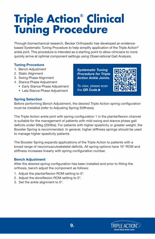
Triple Action® Clinical Tuning ProcedureThrough biomechanical research, Becker Orthopedic has developed an evidence-based Systematic Tuning Procedure to help simplify application of the Triple Action® ankle joint. This procedure is intended as a starting point to allow clinicians to more quickly arrive at optimal component settings using Observational Gait Analysis.
Spring SelectionBefore performing Bench Adjustment, the desired Triple Action spring configuration must be installed (refer to Adjusting Spring Stiffness).
The Triple Action ankle joint with spring configuration 1 in the plantarflexion channel is suitable for the management of patients with mild swing and stance phase gait deficits under 90kg (200lbs). For patients with higher spasticity or greater weight, the Booster Spring is recommended. In general, higher stiffness springs should be used to manage higher spasticity patients.
The Booster Spring expands applications of the Triple Action to patients with a broad range of neuromusculoskeletal deficits. All spring options have 10° ROM and stiffness increases linearly with spring configuration number.
Bench AdjustmentAfter the desired spring configuration has been installed and prior to fitting the orthosis, bench adjust the component as follows:1. Adjust the plantarflexion ROM setting to 0°.2. Adjust the dorsiflexion ROM setting to 0°.3. Set the ankle alignment to 0°.
Systematic Tuning Procedure for Triple Action Ankle Joints.
To view, please scan the QR Code
®
Small Adult Ankle Joint10.
Static Alignment (PF and DF ROM at 0°)Don the orthosis and shoes to the patient and perform static alignment with the patient standing. Adjust the ankle angle with the ROM settings locked at 0° to tune for knee stability. The knee should be slightly flexed to place the weight line over the midfoot and improve the patient’s sense of standing balance and stability. Avoid aligning the ankle to the patient’s maximum ROM in dorsiflexion when making this adjustment. If there is insufficient dorsiflexion ROM to make this adjustment due to a gastrosoleus contracture, a heel lift or shoe modification may be necessary.
Toe Clearance (left) and Foot to Floor Angle (right)
Swing Phase Alignment (PF and DF ROM at 0°)With the patient walking, and the ROM settings still locked at 0°, adjust the alignment setting to improve toe clearance in mid swing and foot position at initial contact. Observe the foot to floor angle while making this adjustment. Note that increasing dorsiflexion alignment may reduce knee extension at terminal swing if there is gastrocnemius tone or contracture. Also observe and optimize for step length symmetry while making this adjustment.
®
Small Adult Ankle Joint11.
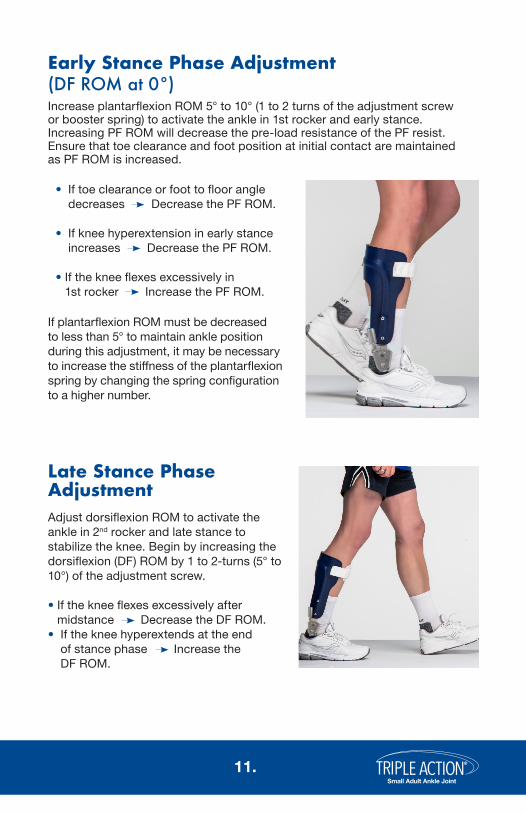
• If toe clearance or foot to floor angle decreases Decrease the PF ROM.
• If knee hyperextension in early stance increases Decrease the PF ROM.
• If the knee flexes excessively in 1st rocker Increase the PF ROM.
Early Stance Phase Adjustment(DF ROM at 0°)Increase plantarflexion ROM 5° to 10° (1 to 2 turns of the adjustment screw or booster spring) to activate the ankle in 1st rocker and early stance. Increasing PF ROM will decrease the pre-load resistance of the PF resist. Ensure that toe clearance and foot position at initial contact are maintained as PF ROM is increased.
Late Stance Phase AdjustmentAdjust dorsiflexion ROM to activate the ankle in 2nd rocker and late stance to stabilize the knee. Begin by increasing the dorsiflexion (DF) ROM by 1 to 2-turns (5° to 10°) of the adjustment screw.
• If the knee flexes excessively after midstance Decrease the DF ROM.
• If the knee hyperextends at the end of stance phase Increase the DF ROM.
If plantarflexion ROM must be decreased to less than 5° to maintain ankle position during this adjustment, it may be necessary to increase the stiffness of the plantarflexion spring by changing the spring configuration to a higher number.
®
Small Adult Ankle Joint12.
MaintenancePrior to assembly of the Alignment Tool, the Upper Bar and Stirrup must be removed from the Triple Action component body. Use the following procedure to disassemble the component:
1. Remove the cam nut using a 15mm socket wrench. 2. Remove the pivot bushing screw using the M4 hex wrench.3. Remove the pivot bushing and upper bar.4. Remove the stirrup.5. Remove the wear plates from the stirrup.
Disassembly
1
2
3
5
4
®
Small Adult Ankle Joint13.
Note: The bar attachment screws (not included) should be coated with thread locking adhesive prior to final assembly.
Re-assemble the Triple Action ankle joint after fabrication.
Assembly
Lubricate the cam slot in the upper bar with Teflon grease (included).
Insert the pivot bushing through the hole in the upper bar and part way into the component body.Apply medium strength thread locker to the cam nut and loosely install.
1.
2.
3.
4.
Tighten cam nut to 10Nm using a 15mm socket and torque wrench.
Apply medium strength thread locker to pivot screw, install and torque to 10Nm using a torque wrench.
Push pivot bushing through wear plates and stirrup and ensure the head of the bushing is fully seated in upper bar.
Insert stirrup between the wear plates into clevis.
7.
8.
9.
10.
Maintenance
Lubricate the pivot bushing with Teflon grease.
Grease both sides of the head of the stirrup with Teflon grease.Insert wear plates into clevis with the shiny sides toward the stirrup head. Ensure wear plates are correctly oriented as shown.
5.
6.Shiny side should face stirrup
1
2
3
54
6
8
7
9
10
®
Small Adult Ankle Joint14.
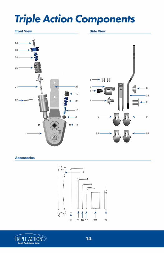
28
8
2
4
7
3
5
9 9
9A9A
Triple Action Components
14
15 16 TG TL1729
22
25
24
23
26
10
6
11
24
18
2821
1
Accessories
Side ViewFront View
®
Small Adult Ankle Joint15.
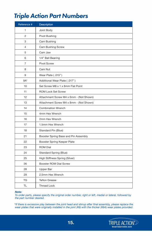
Reference # DescriptionDescription
1 Joint Body
2 Pivot Bushing
3 Cam Bushing
4 Cam Bushing Screw
5 Cam Jaw
6 1/4” Ball Bearing
7 Pivot Screw
8 Cam Nut
9 Wear Plate ( .015” )
9A* Additional Wear Plate ( .017” )
10 Set Screw M8 x 1 x 8mm Flat Point
11 ROM Lock Set Screw
12 Attachment Screw M4 x 6mm - (Not Shown)
13 Attachment Screw M4 x 8mm - (Not Shown)
14 Combination Wrench
15 4mm Hex Wrench
16 2mm Hex Wrench
17 1.5mm Hex Wrench
18 Standard Pin (Blue)
21 Booster Spring Base and Pin Assembly
22 Booster Spring Keeper Plate
23 ROM Dial
24 Standard Spring (Blue)
25 High Stiffness Spring (Silver)
26 Booster ROM Dial Screw
28 Upper Bar
29 2.5mm Hex Wrench
TG Teflon Grease
TL Thread Lock
Triple Action Part Numbers
To order parts, please specify the original order number, right or left, medial or lateral, followed by the part number desired.
Note:
If there is excessive play between the joint head and stirrup after final assembly, please replace the wear plates that were originally installed in the joint (#9) with the thicker (#9A) wear plates provided.*