Small- and Medium-Scale Monitoring and Control System Monitoring and Control System for Safe and Stable Plant Operation High-capacity and high-speed plant control Continuous operation rate improvement through full redundancy Effective use of existing assets through high inheritability 21E1-E-0037g
Transcript
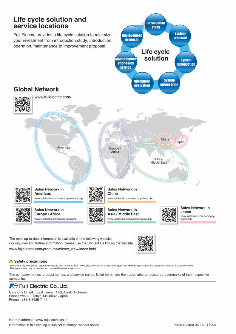
Life cycle solution and service locations
Life cycle solution
Global Network
Fuji Electric provides a life cycle solution to minimize your investment from introduction study, introduction, operation, maintenance to improvement proposal.
www.fujielectric.com/
Asia / Middle East
JapanChina
Europe /Africa
Americas
Sales Network in Americaswww.fujielectric.com/company/america.php
Sales Network in Chinawww.fujielectric.com/company/china.php
Sales Network in Japanwww.fujielectric.com/company/japan.php
Sales Network in Europe / Africawww.fujielectric.com/company/eu.php
Sales Network in Asia / Middle Eastwww.fujielectric.com/company/asia.php
Printed in Japan 2021-3/1.5 FOLS
Gate City Ohsaki, East Tower, 11-2, Osaki 1-chome, Shinagawa-ku, Tokyo 141-0032, JapanPhone : +81-3-5435-7111
Safety precautions• Before use, please read the “Operation Manuals” and “Specifications” thoroughly or consult us or the sales agent from which you purchased this equipment to ensure it is used correctly.• This system must only be handled and operated by relevant specialists.
Internet address : www.fujielectric.co.jpInformation in this catalog is subject to change without notice.
The most up-to-date information is available on the following website. For inquiries and further information, please use the Contact Us link on the website.www.fujielectric.com/products/micrex_view/index.html
The company names, product names, and service names listed herein are the trademarks or registered trademarks of their respectivecompanies.
Small- and Medium-Scale Monitoring and Control System
Monitoring and Control System for Safeand Stable Plant Operation
High-capacity and high-speed plant control
Continuous operation rate improvement through full redundancy
Effective use of existing assets through high inheritability
21E1-E-0037g
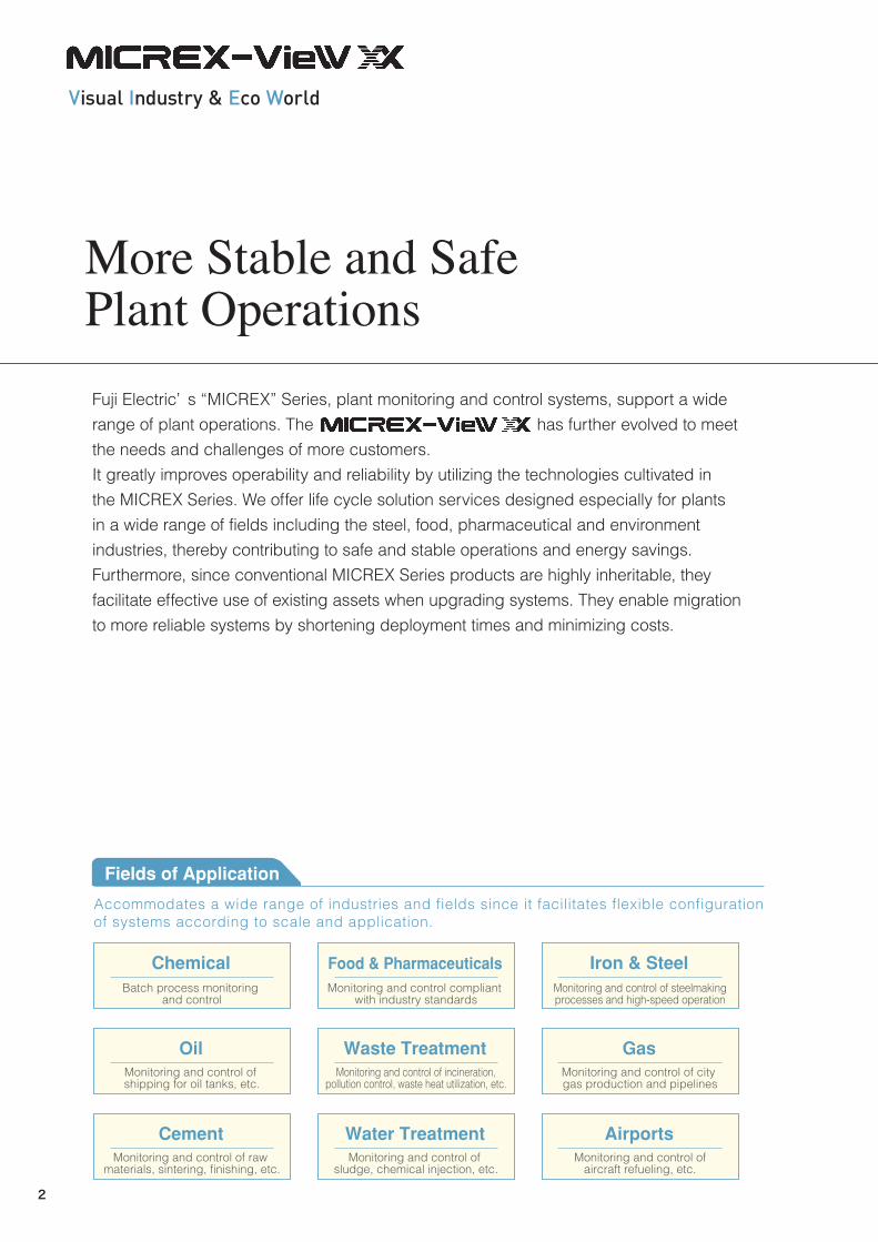
Fuji Electric’ s “MICREX” Series, plant monitoring and control systems, support a wide range of plant operations. The has further evolved to meet the needs and challenges of more customers.It greatly improves operability and reliability by utilizing the technologies cultivated in the MICREX Series. We offer life cycle solution services designed especially for plants in a wide range of fields including the steel, food, pharmaceutical and environment industries, thereby contributing to safe and stable operations and energy savings.Furthermore, since conventional MICREX Series products are highly inheritable, they facilitate effective use of existing assets when upgrading systems. They enable migration to more reliable systems by shortening deployment times and minimizing costs.
More Stable and Safe Plant Operations
Accommodates a wide range of industries and fields since it facilitates flexible configurationof systems according to scale and application.
ChemicalBatch process monitoring
and control
Food & PharmaceuticalsMonitoring and control compliant
with industry standards
Iron & SteelMonitoring and control of steelmakingprocesses and high-speed operation
OilMonitoring and control of shipping for oil tanks, etc.
Waste TreatmentMonitoring and control of incineration,
pollution control, waste heat utilization, etc.
GasMonitoring and control of city gas production and pipelines
CementMonitoring and control of raw
materials, sintering, finishing, etc.
Water TreatmentMonitoring and control of
sludge, chemical injection, etc.
AirportsMonitoring and control of
aircraft refueling, etc.
5 Features Table of ContentsApplicable Fieldsand Features
System Configuration
Monitoring Operation
Control
Engineering Capability
High Reliability
High Inheritability
System Specifications List
Life Cycle SolutionService Bases
P2
P4
P6
P8
P10
P12
P14
P15
P16
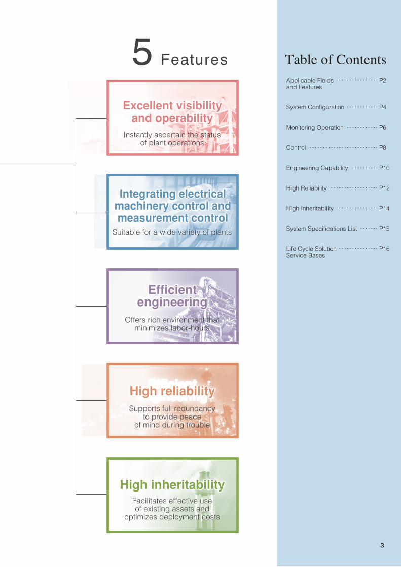
Excellent visibilityand operability
Instantly ascertain the statusof plant operations
Suitable for a wide variety of plants
Facilitates effective useof existing assets and
optimizes deployment costs
Integrating electricalmachinery control andmeasurement control
Efficientengineering
High inheritability
Excellent visibilityand operability
Integrating electricalmachinery control andmeasurement control
Supports full redundancyto provide peace
of mind during trouble
High reliabilityHigh reliability
Offers rich environment thatminimizes labor-hours
Efficientengineering
Efficientengineering
High inheritability
Fields of Application
2
Fuji Electric’ s “MICREX” Series, plant monitoring and control systems, support a wide range of plant operations. The has further evolved to meet the needs and challenges of more customers.It greatly improves operability and reliability by utilizing the technologies cultivated in the MICREX Series. We offer life cycle solution services designed especially for plants in a wide range of fields including the steel, food, pharmaceutical and environment industries, thereby contributing to safe and stable operations and energy savings.Furthermore, since conventional MICREX Series products are highly inheritable, they facilitate effective use of existing assets when upgrading systems. They enable migration to more reliable systems by shortening deployment times and minimizing costs.
More Stable and Safe Plant Operations
Accommodates a wide range of industries and fields since it facilitates flexible configurationof systems according to scale and application.
ChemicalBatch process monitoring
and control
Food & PharmaceuticalsMonitoring and control compliant
with industry standards
Iron & SteelMonitoring and control of steelmakingprocesses and high-speed operation
OilMonitoring and control of shipping for oil tanks, etc.
Waste TreatmentMonitoring and control of incineration,
pollution control, waste heat utilization, etc.
GasMonitoring and control of city gas production and pipelines
CementMonitoring and control of raw
materials, sintering, finishing, etc.
Water TreatmentMonitoring and control of
sludge, chemical injection, etc.
AirportsMonitoring and control of
aircraft refueling, etc.
5 Features Table of ContentsApplicable Fieldsand Features
System Configuration
Monitoring Operation
Control
Engineering Capability
High Reliability
High Inheritability
System Specifications List
Life Cycle SolutionService Bases
P2
P4
P6
P8
P10
P12
P14
P15
P16
Excellent visibilityand operability
Instantly ascertain the statusof plant operations
Suitable for a wide variety of plants
Facilitates effective useof existing assets and
optimizes deployment costs
Integrating electricalmachinery control andmeasurement control
Efficientengineering
High inheritability
Excellent visibilityand operability
Integrating electricalmachinery control andmeasurement control
Supports full redundancyto provide peace
of mind during trouble
High reliabilityHigh reliability
Offers rich environment thatminimizes labor-hours
Efficientengineering
Efficientengineering
High inheritability
Fields of Application
3
Remote monitoring operation
PrinterHost system
DPCS-F
High-reliability I/O, E-SX I/O
Existing I/O
Field equipment
Existing operatorstation
Existing databasestation
Existing controlstation
Database stationDatabase station
Operator stationOperator station
Control station
Existing control station
Network adapter
Engineeringstation
Remoteconnection
station
OPC UAserver
Information LAN Ethernet
Control LAN FL-net Ver.3-compliant LAN
Ethernet EPAP
(10BASE-2)
T-link
E-SX bus
Existing PLC
PE-linkPlant data recorderPlant data recorder
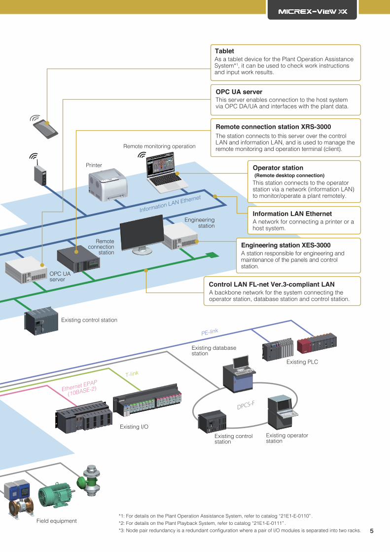
*1: For details on the Plant Operation Assistance System, refer to catalog “21E1-E-0110” .*2: For details on the Plant Playback System, refer to catalog “21E1-E-0111” .*3: Node pair redundancy is a redundant configuration where a pair of I/O modules is separated into two racks.
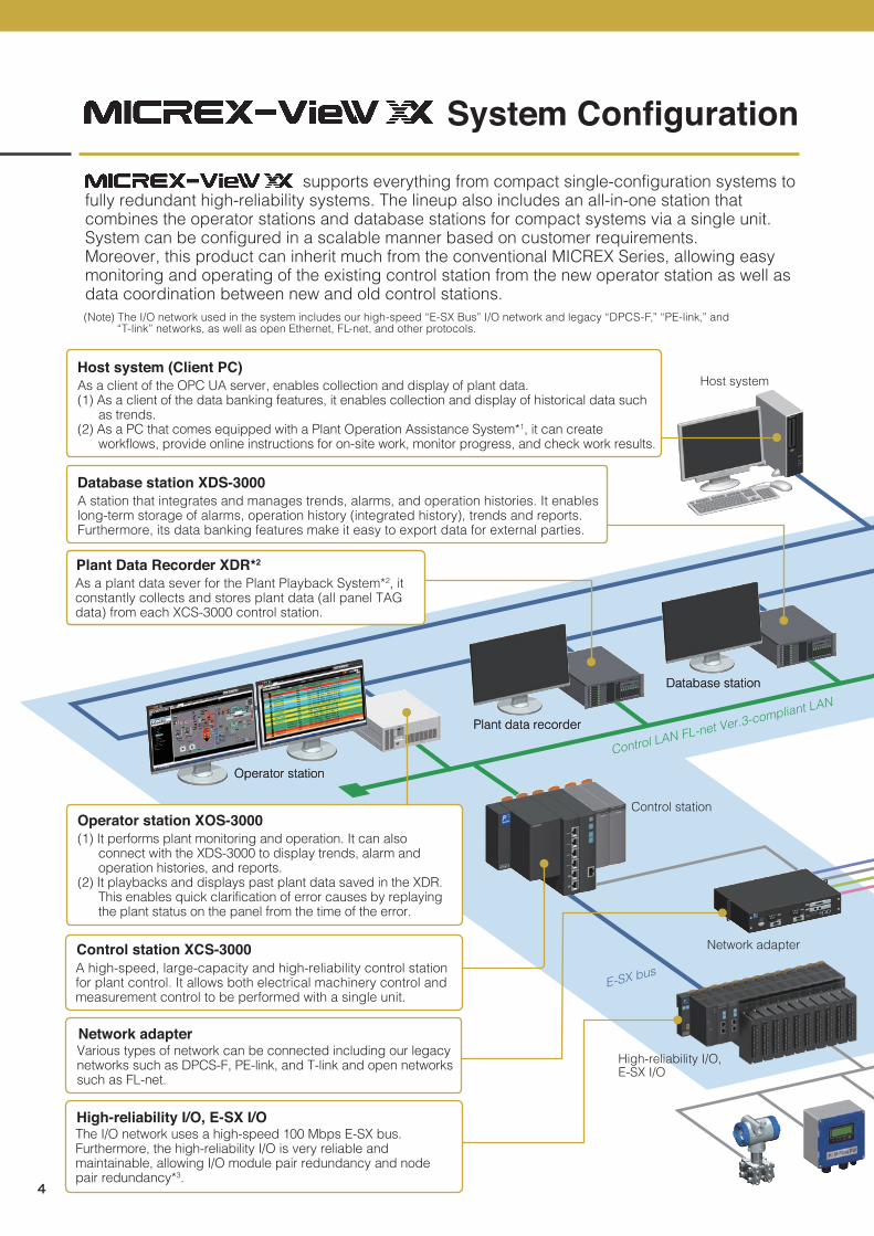
(Note) The I/O network used in the system includes our high-speed “E-SX Bus” I/O network and legacy “DPCS-F,” “PE-link,” and “T-link” networks, as well as open Ethernet, FL-net, and other protocols.
A high-speed, large-capacity and high-reliability control station for plant control. It allows both electrical machinery control and measurement control to be performed with a single unit.
Control station XCS-3000
Various types of network can be connected including our legacy networks such as DPCS-F, PE-link, and T-link and open networks such as FL-net.
Network adapter
The I/O network uses a high-speed 100 Mbps E-SX bus.Furthermore, the high-reliability I/O is very reliable and maintainable, allowing I/O module pair redundancy and node pair redundancy*3.
High-reliability I/O, E-SX I/O
As a plant data sever for the Plant Playback System*2, it constantly collects and stores plant data (all panel TAG data) from each XCS-3000 control station.
Plant Data Recorder XDR*2
As a client of the OPC UA server, enables collection and display of plant data. (1) As a client of the data banking features, it enables collection and display of historical data such
as trends.(2) As a PC that comes equipped with a Plant Operation Assistance System*1, it can create
workflows, provide online instructions for on-site work, monitor progress, and check work results.
Host system (Client PC)
(1) It performs plant monitoring and operation. It can also connect with the XDS-3000 to display trends, alarm and operation histories, and reports.
(2) It playbacks and displays past plant data saved in the XDR. This enables quick clarification of error causes by replaying the plant status on the panel from the time of the error.
Operator station XOS-3000
A station that integrates and manages trends, alarms, and operation histories. It enables long-term storage of alarms, operation history (integrated history), trends and reports. Furthermore, its data banking features make it easy to export data for external parties.
Database station XDS-3000
A station responsible for engineering and maintenance of the panels and control station.
Engineering station XES-3000
This server enables connection to the host system via OPC DA/UA and interfaces with the plant data.
OPC UA server
The station connects to this server over the control LAN and information LAN, and is used to manage the remote monitoring and operation terminal (client).
Remote connection station XRS-3000
This station connects to the operator station via a network (information LAN) to monitor/operate a plant remotely.
Operator station (Remote desktop connection)
A network for connecting a printer or a host system.
Information LAN Ethernet
A backbone network for the system connecting the operator station, database station and control station.
Control LAN FL-net Ver.3-compliant LAN
As a tablet device for the Plant Operation Assistance System*1, it can be used to check work instructions and input work results.
Tablet
supports everything from compact single-configuration systems to fully redundant high-reliability systems. The lineup also includes an all-in-one station that combines the operator stations and database stations for compact systems via a single unit. System can be configured in a scalable manner based on customer requirements.Moreover, this product can inherit much from the conventional MICREX Series, allowing easy monitoring and operating of the existing control station from the new operator station as well as data coordination between new and old control stations.
System Configuration
4
Remote monitoring operation
PrinterHost system
DPCS-F
High-reliability I/O, E-SX I/O
Existing I/O
Field equipment
Existing operatorstation
Existing databasestation
Existing controlstation
Database stationDatabase station
Operator stationOperator station
Control station
Existing control station
Network adapter
Engineeringstation
Remoteconnection
station
OPC UAserver
Information LAN Ethernet
Control LAN FL-net Ver.3-compliant LAN
Ethernet EPAP
(10BASE-2)
T-link
E-SX bus
Existing PLC
PE-linkPlant data recorderPlant data recorder
*1: For details on the Plant Operation Assistance System, refer to catalog “21E1-E-0110” .*2: For details on the Plant Playback System, refer to catalog “21E1-E-0111” .*3: Node pair redundancy is a redundant configuration where a pair of I/O modules is separated into two racks.
(Note) The I/O network used in the system includes our high-speed “E-SX Bus” I/O network and legacy “DPCS-F,” “PE-link,” and “T-link” networks, as well as open Ethernet, FL-net, and other protocols.
A high-speed, large-capacity and high-reliability control station for plant control. It allows both electrical machinery control and measurement control to be performed with a single unit.
Control station XCS-3000
Various types of network can be connected including our legacy networks such as DPCS-F, PE-link, and T-link and open networks such as FL-net.
Network adapter
The I/O network uses a high-speed 100 Mbps E-SX bus.Furthermore, the high-reliability I/O is very reliable and maintainable, allowing I/O module pair redundancy and node pair redundancy*3.
High-reliability I/O, E-SX I/O
As a plant data sever for the Plant Playback System*2, it constantly collects and stores plant data (all panel TAG data) from each XCS-3000 control station.
Plant Data Recorder XDR*2
As a client of the OPC UA server, enables collection and display of plant data. (1) As a client of the data banking features, it enables collection and display of historical data such
as trends.(2) As a PC that comes equipped with a Plant Operation Assistance System*1, it can create
workflows, provide online instructions for on-site work, monitor progress, and check work results.
Host system (Client PC)
(1) It performs plant monitoring and operation. It can also connect with the XDS-3000 to display trends, alarm and operation histories, and reports.
(2) It playbacks and displays past plant data saved in the XDR. This enables quick clarification of error causes by replaying the plant status on the panel from the time of the error.
Operator station XOS-3000
A station that integrates and manages trends, alarms, and operation histories. It enables long-term storage of alarms, operation history (integrated history), trends and reports. Furthermore, its data banking features make it easy to export data for external parties.
Database station XDS-3000
A station responsible for engineering and maintenance of the panels and control station.
Engineering station XES-3000
This server enables connection to the host system via OPC DA/UA and interfaces with the plant data.
OPC UA server
The station connects to this server over the control LAN and information LAN, and is used to manage the remote monitoring and operation terminal (client).
Remote connection station XRS-3000
This station connects to the operator station via a network (information LAN) to monitor/operate a plant remotely.
Operator station (Remote desktop connection)
A network for connecting a printer or a host system.
Information LAN Ethernet
A backbone network for the system connecting the operator station, database station and control station.
Control LAN FL-net Ver.3-compliant LAN
As a tablet device for the Plant Operation Assistance System*1, it can be used to check work instructions and input work results.
Tablet
supports everything from compact single-configuration systems to fully redundant high-reliability systems. The lineup also includes an all-in-one station that combines the operator stations and database stations for compact systems via a single unit. System can be configured in a scalable manner based on customer requirements.Moreover, this product can inherit much from the conventional MICREX Series, allowing easy monitoring and operating of the existing control station from the new operator station as well as data coordination between new and old control stations.
System Configuration
5
*1: Middleware providing panel functions such as multi-window and multi-display. On the multi-window platform, panel applications can be operated individually, and panel functions can be added, updated and deleted easily.
Integrated history panel(Integrated and individual displays selectable)
The database station includes the OPC UA interface as standard, which allows easy cooperation with other systems.
Open interface
The integrated history panel that merges alarm and operation histories provides various sort and search functions to allow quick analysis of problem factors.
Quick troubleshooting
(1,920 x 1,080) and up to four display units can be connected per operator station. The panel uses basic colors based on the color universal design to prevent false recognition and easy-to-identify icons, which ensures excellent visibility.
Excellent visibility
Up to eight operation panels can be displayed as windows or tabs. In addition, you can freely change, enlarge or reduce the layout. The layout of the instrument diagrams on the group panel can also be changed as desired, so that operators can use a layout suitable for operation. Moreover, the trend panel allows enlarging and reducing the point of interest with easy mouse operation, offering excellent operability.
Excellent operability
Microsoft Office, Adobe Reader and other Windows applications can be started from the operation panel. You can analyze data while monitoring/operating a plant.
Cooperation with Windowsapplications
The operator station is a global system supporting multiple languages.
Global support
You can set user privileges or grouping to prevent erroneous operation or system tampering. antivirus software*2 onto the operator station or database station prevents the system from the threat of viruses.
*2: Antivirus software is designated by Fuji Electric. A whitelisting method has been adopted to control the starting of applications based on a list registering only applications allowed for activation.
High security
● Split display● Multi-window display
XCS-3000 (control circuit) monitoring panel
Process operation and abnormal conditions can be monitored easily from the plant panel, thereby helping to check operating conditions and facilitating data analysis. The monitor panel is displayed in an easy-to-understand instrument flow diagram (see HEART-BELIEVE on P13).
Navigation Features
Plant panel
● Trend panel: Enlarged/reduced display
Drag with the mouse. Enlarged display
● Group panel: Free layout switching of instrument diagrams● Enlarged/reduced panel display
Select numerical values
Monitoring/operationfunctions Excellent visibility and operability
The operator station has achieved excellent visibility and operability through the adoption of Fuji Electric's original multi-window platform*1.
6
*1: Middleware providing panel functions such as multi-window and multi-display. On the multi-window platform, panel applications can be operated individually, and panel functions can be added, updated and deleted easily.
Integrated history panel(Integrated and individual displays selectable)
The database station includes the OPC UA interface as standard, which allows easy cooperation with other systems.
Open interface
The integrated history panel that merges alarm and operation histories provides various sort and search functions to allow quick analysis of problem factors.
Quick troubleshooting
(1,920 x 1,080) and up to four display units can be connected per operator station. The panel uses basic colors based on the color universal design to prevent false recognition and easy-to-identify icons, which ensures excellent visibility.
Excellent visibility
Up to eight operation panels can be displayed as windows or tabs. In addition, you can freely change, enlarge or reduce the layout. The layout of the instrument diagrams on the group panel can also be changed as desired, so that operators can use a layout suitable for operation. Moreover, the trend panel allows enlarging and reducing the point of interest with easy mouse operation, offering excellent operability.
Excellent operability
Microsoft Office, Adobe Reader and other Windows applications can be started from the operation panel. You can analyze data while monitoring/operating a plant.
Cooperation with Windowsapplications
The operator station is a global system supporting multiple languages.
Global support
You can set user privileges or grouping to prevent erroneous operation or system tampering. antivirus software*2 onto the operator station or database station prevents the system from the threat of viruses.
*2: Antivirus software is designated by Fuji Electric. A whitelisting method has been adopted to control the starting of applications based on a list registering only applications allowed for activation.
High security
● Split display● Multi-window display
XCS-3000 (control circuit) monitoring panel
Process operation and abnormal conditions can be monitored easily from the plant panel, thereby helping to check operating conditions and facilitating data analysis. The monitor panel is displayed in an easy-to-understand instrument flow diagram (see HEART-BELIEVE on P13).
Navigation Features
Plant panel
● Trend panel: Enlarged/reduced display
Drag with the mouse. Enlarged display
● Group panel: Free layout switching of instrument diagrams● Enlarged/reduced panel display
Select numerical values
Monitoring/operationfunctions Excellent visibility and operability
The operator station has achieved excellent visibility and operability through the adoption of Fuji Electric's original multi-window platform*1.
7
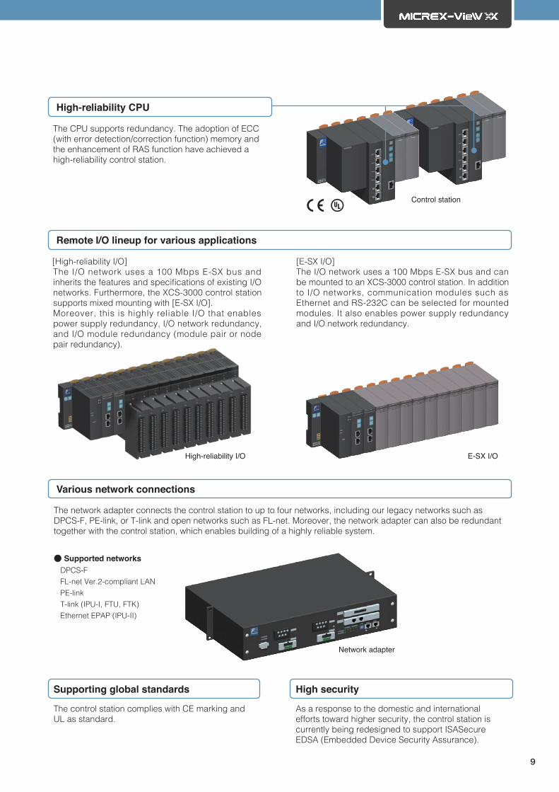
[High-reliability I/O]The I/O network uses a 100 Mbps E-SX bus and inherits the features and specifications of existing I/O networks. Furthermore, the XCS-3000 control station supports mixed mounting with [E-SX I/O].Moreover, this is highly reliable I/O that enables power supply redundancy, I/O network redundancy, and I/O module redundancy (module pair or node pair redundancy).
[E-SX I/O]The I/O network uses a 100 Mbps E-SX bus and can be mounted to an XCS-3000 control station. In addition to I/O networks, communication modules such as Ethernet and RS-232C can be selected for mounted modules. It also enables power supply redundancy and I/O network redundancy.
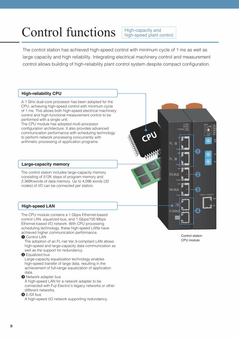
A 1 GHz dual-core processor has been adopted for the CPU, achieving high-speed control with minimum cycle of 1 ms. This allows both high-speed electrical machinery control and high-functional measurement control to be performed with a single unit.The CPU module has adopted multi-processor configuration architecture. It also provides advanced communication performance with scheduling technology to perform network processing concurrently with arithmetic processing of application programs.
High-reliability CPU
The network adapter connects the control station to up to four networks, including our legacy networks such as DPCS-F, PE-link, or T-link and open networks such as FL-net. Moreover, the network adapter can also be redundant together with the control station, which enables building of a highly reliable system.
The control station complies with CE marking and UL as standard.
Supporting global standards
Large-capacity memory
The control station includes large-capacity memory consisting of 512K steps of program memory and 2,368Kwords of data memory. Up to 4,096 words (32 nodes) of I/O can be connected per station.
High-reliability I/O
Network adapter
E-SX I/O
As a response to the domestic and international efforts toward higher security, the control station is currently being redesigned to support ISASecure EDSA (Embedded Device Security Assurance).
High security
High-reliability CPU
The CPU supports redundancy. The adoption of ECC (with error detection/correction function) memory and the enhancement of RAS function have achieved a high-reliability control station.
High-speed LAN
The CPU module contains a 1 Gbps Ethernet-based control LAN, equalized bus, and 1 Gbps/100 Mbps Ethernet-based I/O network. With CPU processing scheduling technology, these high-speed LANs have achieved higher communication performance.❶ Control LAN
The adoption of an FL-net Ver.3-compliant LAN allows high-speed and large-capacity data communication as well as the support for redundancy.❷ Equalized bus
Large-capacity equalization technology enables high-speed transfer of large data, resulting in the achievement of full-range equalization of application data.❸ Network adapter bus
A high-speed LAN for a network adapter to be connected with Fuji Electric's legacy networks or other different networks.❹ E-SX bus
A high-speed I/O network supporting redundancy.
Control stationCPU module
Control station
Control functionsThe control station has achieved high-speed control with minimum cycle of 1 ms as well as large capacity and high reliability. Integrating electrical machinery control and measurement control allows building of high-reliability plant control system despite compact configuration.
Remote I/O lineup for various applications
Various network connections
High-capacity and high-speed plant control
8
[High-reliability I/O]The I/O network uses a 100 Mbps E-SX bus and inherits the features and specifications of existing I/O networks. Furthermore, the XCS-3000 control station supports mixed mounting with [E-SX I/O].Moreover, this is highly reliable I/O that enables power supply redundancy, I/O network redundancy, and I/O module redundancy (module pair or node pair redundancy).
[E-SX I/O]The I/O network uses a 100 Mbps E-SX bus and can be mounted to an XCS-3000 control station. In addition to I/O networks, communication modules such as Ethernet and RS-232C can be selected for mounted modules. It also enables power supply redundancy and I/O network redundancy.
A 1 GHz dual-core processor has been adopted for the CPU, achieving high-speed control with minimum cycle of 1 ms. This allows both high-speed electrical machinery control and high-functional measurement control to be performed with a single unit.The CPU module has adopted multi-processor configuration architecture. It also provides advanced communication performance with scheduling technology to perform network processing concurrently with arithmetic processing of application programs.
High-reliability CPU
The network adapter connects the control station to up to four networks, including our legacy networks such as DPCS-F, PE-link, or T-link and open networks such as FL-net. Moreover, the network adapter can also be redundant together with the control station, which enables building of a highly reliable system.
The control station complies with CE marking and UL as standard.
Supporting global standards
Large-capacity memory
The control station includes large-capacity memory consisting of 512K steps of program memory and 2,368Kwords of data memory. Up to 4,096 words (32 nodes) of I/O can be connected per station.
High-reliability I/O
Network adapter
E-SX I/O
As a response to the domestic and international efforts toward higher security, the control station is currently being redesigned to support ISASecure EDSA (Embedded Device Security Assurance).
High security
High-reliability CPU
The CPU supports redundancy. The adoption of ECC (with error detection/correction function) memory and the enhancement of RAS function have achieved a high-reliability control station.
High-speed LAN
The CPU module contains a 1 Gbps Ethernet-based control LAN, equalized bus, and 1 Gbps/100 Mbps Ethernet-based I/O network. With CPU processing scheduling technology, these high-speed LANs have achieved higher communication performance.❶ Control LAN
The adoption of an FL-net Ver.3-compliant LAN allows high-speed and large-capacity data communication as well as the support for redundancy.❷ Equalized bus
Large-capacity equalization technology enables high-speed transfer of large data, resulting in the achievement of full-range equalization of application data.❸ Network adapter bus
A high-speed LAN for a network adapter to be connected with Fuji Electric's legacy networks or other different networks.❹ E-SX bus
A high-speed I/O network supporting redundancy.
Control stationCPU module
Control station
Control functionsThe control station has achieved high-speed control with minimum cycle of 1 ms as well as large capacity and high reliability. Integrating electrical machinery control and measurement control allows building of high-reliability plant control system despite compact configuration.
Remote I/O lineup for various applications
Various network connections
High-capacity and high-speed plant control
9
Engineering functionThe engineering station integrated the engineering environments of the HCI*1 (panel, database) and control station. It also has full functionality such as parts packages and machine-less simulation function to provide an effective engineering environment.
This has achieved the vertical cooperation of HCI engineering and control station engineering through integrated management of TAG and the horizontal cooperation of engineering between control stations through integrated management of inter-station communication memory. There are also various excellent operation functions for effective engineering, such as drag-and-drop or copy-and-paste from a program tree and exporting/importing definitions.
Integrated engineering environment
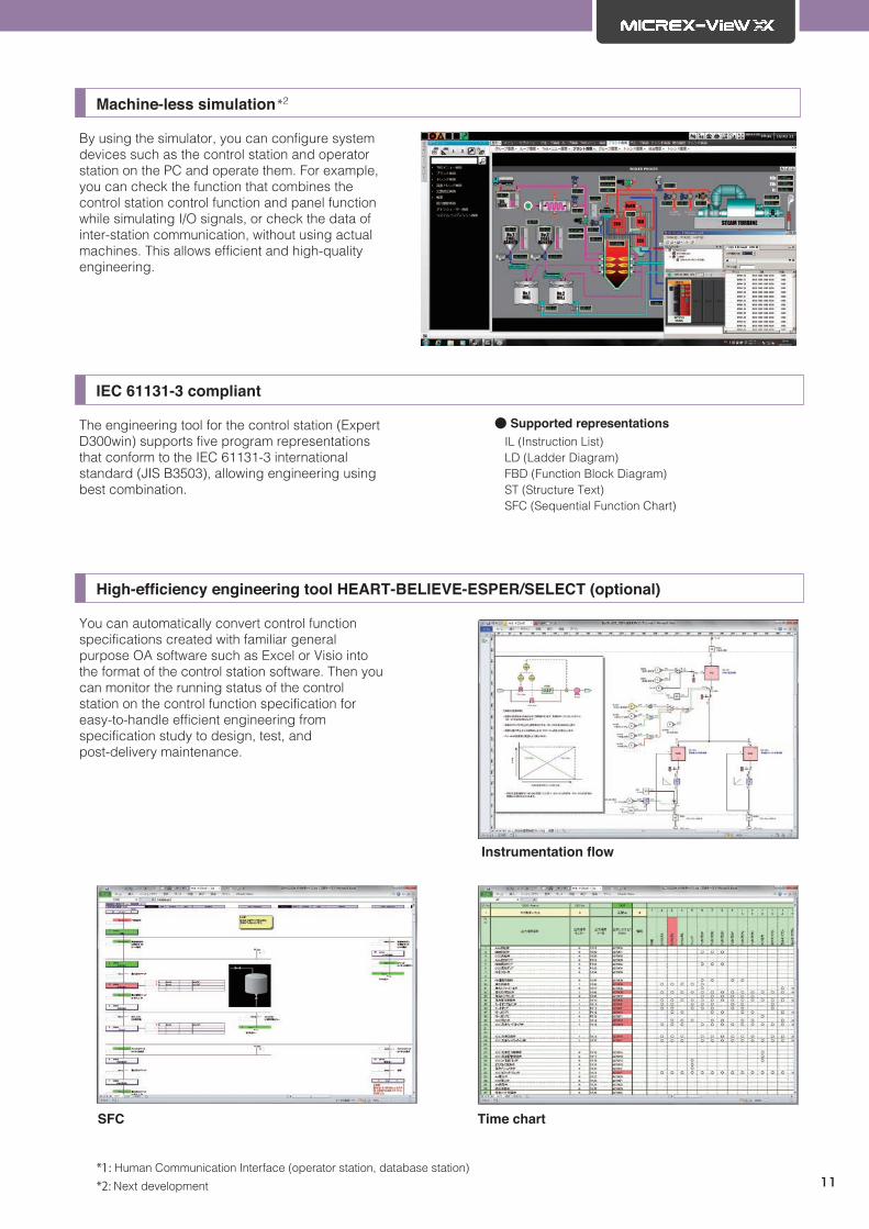
Machine-less simulation*2
By using the simulator, you can configure system devices such as the control station and operator station on the PC and operate them. For example, you can check the function that combines the control station control function and panel function while simulating I/O signals, or check the data of inter-station communication, without using actual machines. This allows efficient and high-quality engineering.
IEC 61131-3 compliant
The engineering tool for the control station (Expert D300win) supports five program representations that conform to the IEC 61131-3 international standard (JIS B3503), allowing engineering using best combination.
You can automatically convert control function specifications created with familiar general purpose OA software such as Excel or Visio into the format of the control station software. Then you can monitor the running status of the control station on the control function specification for easy-to-handle efficient engineering from specification study to design, test, and post-delivery maintenance.
*1: Human Communication Interface (operator station, database station)
*2: Next development
Integrated managem
ent of TAG
[Vertical cooperation]
Integrated management of inter-station communication memory [Horizontal cooperation]
Efficient engineering
10
Engineering functionThe engineering station integrated the engineering environments of the HCI*1 (panel, database) and control station. It also has full functionality such as parts packages and machine-less simulation function to provide an effective engineering environment.
This has achieved the vertical cooperation of HCI engineering and control station engineering through integrated management of TAG and the horizontal cooperation of engineering between control stations through integrated management of inter-station communication memory. There are also various excellent operation functions for effective engineering, such as drag-and-drop or copy-and-paste from a program tree and exporting/importing definitions.
Integrated engineering environment
Machine-less simulation*2
By using the simulator, you can configure system devices such as the control station and operator station on the PC and operate them. For example, you can check the function that combines the control station control function and panel function while simulating I/O signals, or check the data of inter-station communication, without using actual machines. This allows efficient and high-quality engineering.
IEC 61131-3 compliant
The engineering tool for the control station (Expert D300win) supports five program representations that conform to the IEC 61131-3 international standard (JIS B3503), allowing engineering using best combination.
You can automatically convert control function specifications created with familiar general purpose OA software such as Excel or Visio into the format of the control station software. Then you can monitor the running status of the control station on the control function specification for easy-to-handle efficient engineering from specification study to design, test, and post-delivery maintenance.
*1: Human Communication Interface (operator station, database station)
*2: Next development
Integrated managem
ent of TAG
[Vertical cooperation]
Integrated management of inter-station communication memory [Horizontal cooperation]
Efficient engineering
11
External terminal I/O direct configuration eliminates internal wiring. Also enables conventional cabling to support various installation environments. Shortens construction period during switchover through reuse of existing terminal blocks. Furthermore, decreases costs through node reduction via high-density mounting of I/O modules.
Standardization of I/O panel wiring
Compliant with the HART communication standard for the HART protocol. Supports maintainability of field devices and stability of plant operations (Coming soon).
HART communication compliant
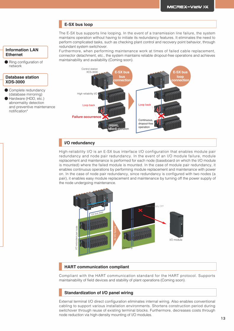
The E-SX bus supports line looping. In the event of a transmission line failure, the system maintains operation without having to initiate its redundancy features. It eliminates the need to perform complicated tasks, such as checking plant control and recovery point behavior, through redundant system switchover.Furthermore, when performing maintenance work at times of failed cable replacement, connector detachment, etc., the system maintains reliable dropout-free operations and achieves maintainability and availability (Coming soon).
E-SX bus loop
E-SX busloop
connection
E-SX busbus
connection
Failure occurrence
Loop back Loop back
Dropout, fail-soft operation
Continuous, dropout-free operation
Control stationXCS-3000
High reliability I/O
High-reliability I/O is an E-SX bus interface I/O configuration that enables module pair redundancy and node pair redundancy. In the event of an I/O module failure, module replacement and maintenance is performed for each node (baseboard on which the I/O module is mounted) where the failed module is mounted. In the case of module pair redundancy, it enables continuous operations by performing module replacement and maintenance with power on. In the case of node pair redundancy, since redundancy is configured with two nodes (a pair), it enables easy module replacement and maintenance by turning off the power supply of the node undergoing maintenance.
Information LAN Ethernet● Ring configuration of network
Equalized
bus
Ethernet
E-SX bus
● CPU redundancy (warm standby)● High-speed large-capacity equalization (equalized engineering- less)● ECC (Error Check and Correct) memory● Excellent RAS (message display, larger-capacity history storage)
Control station XCS-3000
● Power supply redundancy● I/O network redundancy (E-SX bus)● I/O module redundancy (module pair)● Node pair redundancy● E-SX bus loop
High reliability I/O
*: In conjunction with vendor-provided tools, the database station automatically detects when a hardware (HDD, etc.) abnormality occurs or when replacement is recommended and notifies the monitoring system of such information (Please contact us for more information on vendor-provided tools).
High reliabilityThe achieves better reliability by providing redundancy for all system components, including operator stations, control stations, power supplies, control LANs, and I/O networks.
Contiunuous operation rate improvement through full redundancy
Equalized busEqualized bus
Equalized busEqualized bus
Equalized busEqualized bus
12
External terminal I/O direct configuration eliminates internal wiring. Also enables conventional cabling to support various installation environments. Shortens construction period during switchover through reuse of existing terminal blocks. Furthermore, decreases costs through node reduction via high-density mounting of I/O modules.
Standardization of I/O panel wiring
Compliant with the HART communication standard for the HART protocol. Supports maintainability of field devices and stability of plant operations (Coming soon).
HART communication compliant
The E-SX bus supports line looping. In the event of a transmission line failure, the system maintains operation without having to initiate its redundancy features. It eliminates the need to perform complicated tasks, such as checking plant control and recovery point behavior, through redundant system switchover.Furthermore, when performing maintenance work at times of failed cable replacement, connector detachment, etc., the system maintains reliable dropout-free operations and achieves maintainability and availability (Coming soon).
E-SX bus loop
E-SX busloop
connection
E-SX busbus
connection
Failure occurrence
Loop back Loop back
Dropout, fail-soft operation
Continuous, dropout-free operation
Control stationXCS-3000
High reliability I/O
High-reliability I/O is an E-SX bus interface I/O configuration that enables module pair redundancy and node pair redundancy. In the event of an I/O module failure, module replacement and maintenance is performed for each node (baseboard on which the I/O module is mounted) where the failed module is mounted. In the case of module pair redundancy, it enables continuous operations by performing module replacement and maintenance with power on. In the case of node pair redundancy, since redundancy is configured with two nodes (a pair), it enables easy module replacement and maintenance by turning off the power supply of the node undergoing maintenance.
Information LAN Ethernet● Ring configuration of network
Equalized
bus
Ethernet
E-SX bus
● CPU redundancy (warm standby)● High-speed large-capacity equalization (equalized engineering- less)● ECC (Error Check and Correct) memory● Excellent RAS (message display, larger-capacity history storage)
Control station XCS-3000
● Power supply redundancy● I/O network redundancy (E-SX bus)● I/O module redundancy (module pair)● Node pair redundancy● E-SX bus loop
High reliability I/O
*: In conjunction with vendor-provided tools, the database station automatically detects when a hardware (HDD, etc.) abnormality occurs or when replacement is recommended and notifies the monitoring system of such information (Please contact us for more information on vendor-provided tools).
High reliabilityThe achieves better reliability by providing redundancy for all system components, including operator stations, control stations, power supplies, control LANs, and I/O networks.
Contiunuous operation rate improvement through full redundancy
Equalized busEqualized bus
Equalized busEqualized bus
Equalized busEqualized bus
13
Existing system
HCI updating CTL updating
New HCIExisting HCI
Existing CTL Existing CTL
Existing I/O Existing I/O High-reliability I/O
New CTL
Existing Updated
Existing I/O
New CTL
I/O updating
HCI: Operator station or database station CTL: Control station I/O: Remote I/O
New HCI New HCI
Since the modules can be connected seamlessly with the existing system, the system can be updated in a stepwise manner.
Step-by-step update
Since the system can inherit the existing system's panels and the control station application assets, it can be updated to a highly reliable system within a short period.
Inheritance of existing application assets Inheritance of existing hardware assets
Reduces wiring work and shortens construction periods by enabling connection with existing Fuji Electric system networks (DPCS-F, PE-link) and existing I/O networks via network adapters.
High inheritability can inherit much from the conventional MICREX Series. You can use the existing assets effectively during system updating to ensure switchover to a highly reliable system. This contributes to further stable and safe plant operation.
Using the existing assets effectively
14
Existing system
HCI updating CTL updating
New HCIExisting HCI
Existing CTL Existing CTL
Existing I/O Existing I/O High-reliability I/O
New CTL
Existing Updated
Existing I/O
New CTL
I/O updating
HCI: Operator station or database station CTL: Control station I/O: Remote I/O
New HCI New HCI
Since the modules can be connected seamlessly with the existing system, the system can be updated in a stepwise manner.
Step-by-step update
Since the system can inherit the existing system's panels and the control station application assets, it can be updated to a highly reliable system within a short period.
Inheritance of existing application assets Inheritance of existing hardware assets
Reduces wiring work and shortens construction periods by enabling connection with existing Fuji Electric system networks (DPCS-F, PE-link) and existing I/O networks via network adapters.
High inheritability can inherit much from the conventional MICREX Series. You can use the existing assets effectively during system updating to ensure switchover to a highly reliable system. This contributes to further stable and safe plant operation.
Using the existing assets effectively
15
System specifications listSystem components specifications
Operator station(XOS-3000)
16 units ( for database station deployment. 8 units when using the Plant Data Recorder)
8 units (for all-in-one station deployment)OS*1 : Windows 10 IoT Enterprise 2016 LTSB (64bit version) Windows 7 Professional SP1 (64bit version)LCD : 1,920 x 1,080 (Full HD)USB mouse, USB general purpose keyboard / USB application keyboard (optional)
Database station(XDS-3000)
1 unit (single or redundant)Monitoring and control loop points (Module TAG): 8,640 points (288 x 30), State change points such as contacts (bit state change): 61,440 points, User TAG : 32,752 pointsLCD : 15 inch or larger and 1,024 × 768 or greater resolution are recommended.OS*1 : Windows Server 2016 Standard (64-bit version) Windows Server 2008 R2 Standard (64bit version)
All-in-one station
(XAL-3000)
1 unit (single or redundant)OS*1 : Windows Server 2016 Standard (64-bit version) Windows Server 2008 R2 Standard (64bit version)LCD : 1,920 x 1,080 (Full HD)
Control station(XCS-3000/XCS-3000R)
30 units (for database station deployment. 15 units when using the Plant Data Recorder)10 units (for all-in-one station deployment)Note: All units are standalone or redundant
I/O : IPU-I (T-link), IPU-Ⅱ (Ethernet), SX-I/O (E-SX bus)(However, SX-I/O is only available for XCS-3000)Control LAN: FL-net Ver.3-compliant LANLegacy networks: DPCS-F, PE-LINK
Network printer 8 units
Engineering station(XES-3000)
4 units (FPROCES/Expert/HEART)Computer : Windows PC (IBM PC/AT compatible)OS*1 : Windows10 IoT Enterprise 2016 LTSB (64-bit version) Windows7 (32-bit version)
LCD : 1,024 × 768 or 1,280 × 1,024(1,920 x 1,080 or more is recommended for draw-ing interactive panels)
OPC UA server
16 units (total number of OPC UA servers and XOS- 3000 units)OS*1 : Windows 10 IoT Enterprise 2016 LTSB (64bit version) Windows 7 Professional SP1 (64bit version) (Same as the operator station)Number of connected clients: Up to 8 clientsNumber of subscriptions: Up to 20 subscriptionsNumber of monitored items: up to 20,000 items(Up to 2,500 monitored items per subscription)Data update cycle: 1 second
Remote connection station(XRS-3000)*2
4 unitsOS*1 : Windows Server 2016 Standard (64bit version) Windows Server 2008 R2 Standard (64bit version)LCD : 1,024 × 768 or higher
Plant Data Recorder (XDR)
1 unitOS : Windows Server 2016 Standard (64-bit)LCD : 1,920 x 1,080 (full HD)
Control LAN (FL-net Ver.3-compliant LAN)
Topology Star
No. of stations
Max. 64 units (total number of system compo-nents connected to the control LAN; similar to sin-gle units, redundant XDS and XCS are calculated as one single unit.)
・1,000 Mbit/s: Twisted pair cable (STP, straight, Cat5e or higher, with ferrite core), fiber optic cable (1000BASE-SX, 1000BASE-LX)
Transmission distance
・STP: Uses a switching hub (SW-HUB) or fiber op-tic port based switching hub (optical SW-HUB) for cable extensions with a maximum length of 100 m/segment.
・Optical fiber cable: (1) 100BASE-FX (max. 2 km / segment); (2) 1000BASE-SX (max. 550 m / seg-ment); (3)1000BASE-LX (max. 5 km / segment)
ProtocolFA link protocol/FL-net Ver.3-compliant LAN pro-tocol, UDP/IP, TCP/IP, ICMP, ARP
Communication speed 100 Mbits/sec, 1,000 Mbits/sec
・UTP/STP: 100BASE-TX (max. 100 m / segment); when extending cable, use SW-HUB or optical SW-HUB (optical fiber cable is used for optical SW-HUB)
・Optical fiber cable: 100BASE-FX (max. 2 km / segment)
Protocol TCP/IP, UDP/IP
Communication speed10 Mbits / sec., 100 Mbits / sec.; automatic switch-ing; full duplex
Conformed standard IEEE 802.3u
*1 : If the system versions of are the same, old and new operating systems can be used together.
*2: FL-net (OPCN-2) is an FA network standardized by JEMA (Japan Electrical Manufacturers’ Associa-tion).
Life cycle solution and service locations
Life cycle solution
Global Network
Fuji Electric provides a life cycle solution to minimize your investment from introduction study, introduction, operation, maintenance to improvement proposal.
www.fujielectric.com/
Asia / Middle East
JapanChina
Europe /Africa
Americas
Sales Network in Americaswww.fujielectric.com/company/america.php
Sales Network in Chinawww.fujielectric.com/company/china.php
Sales Network in Japanwww.fujielectric.com/company/japan.php
Sales Network in Europe / Africawww.fujielectric.com/company/eu.php
Sales Network in Asia / Middle Eastwww.fujielectric.com/company/asia.php
Printed in Japan 2021-3/1.5 FOLS
Gate City Ohsaki, East Tower, 11-2, Osaki 1-chome, Shinagawa-ku, Tokyo 141-0032, JapanPhone : +81-3-5435-7111
Safety precautions• Before use, please read the “Operation Manuals” and “Specifications” thoroughly or consult us or the sales agent from which you purchased this equipment to ensure it is used correctly.• This system must only be handled and operated by relevant specialists.
Internet address : www.fujielectric.co.jpInformation in this catalog is subject to change without notice.
The most up-to-date information is available on the following website. For inquiries and further information, please use the Contact Us link on the website.www.fujielectric.com/products/micrex_view/index.html
The company names, product names, and service names listed herein are the trademarks or registered trademarks of their respectivecompanies.
Small- and Medium-Scale Monitoring and Control System
Monitoring and Control System for Safeand Stable Plant Operation
High-capacity and high-speed plant control
Continuous operation rate improvement through full redundancy
Effective use of existing assets through high inheritability