32
SMALL DIAMETER Implant
SMALLDIAMETER Implant
2
Implant characteristics page 04
Dental Implants page 06
Prosthetic components page 10
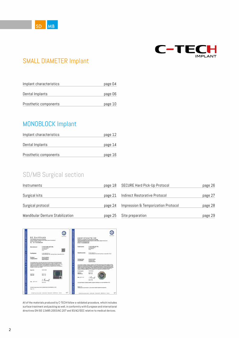
All of the materials produced by C-TECH follow a validated procedure, which includes surface treatment and packing as well, in conformity with European and international directives EN ISO 13485:2003/AC:207 and 93/42/EEC relative to medical devices.
SMALL DIAMETER Implant
Implant characteristics page 12
Dental Implants page 14
Prosthetic components page 16
MONOBLOCK Implant
SD/MB Surgical sectionInstruments page 18
Surgical kits page 21
Surgical protocol page 24
Mandibular Denture Stabilization page 25
SECURE Hard Pick-Up Protocol page 26
Indirect Restorative Protocol page 27
Impression & Temporization Protocol page 28
Site preparation page 29
3
MINI Implant
Dental precision solutionsC-Tech Implant is a dynamic company with aggressive growth, producing components and product lines primarily for dental implantology.
International presence With production and management based in Italy, C-Tech Implant is active in all major world markets and is distributed in over 25 countries.
Scientific research, advanced technology,simplificationC-Tech Implant differentiates itself with attention to research and the application of high technology to its products, all while maintaining a simplicity of insertion and ease of use.
C-Tech Implant incorporates the latest trends in implantology but provides very practical surgical and prosthetic solutions aimed at offering the practitioner and the patient optimal results.
High quality standardsC-Tech Implant products are made to the highest standards governing the manufacturing and management of European medical and dental components. Up to date audits and certifications assure that these standards are vigilantly maintained.
Training & adviceDental professionals are assisted by the rich knowledge and experience of C-Tech Implant personnel and through C-Tech courses and training sessions. During these courses the professional is able to learn the latest methods of implant placement and reconstruction.
Mission statementThe goal of C-Tech Implant is to provide the highest level of quality for technologically advanced products at reasonable prices in order to allow the dental practitioner to find solutions for the broadest range of patients.
4
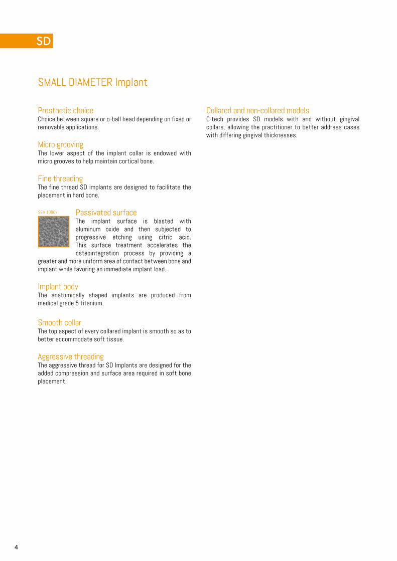
SEM 1000x
SMALL DIAMETER Implant
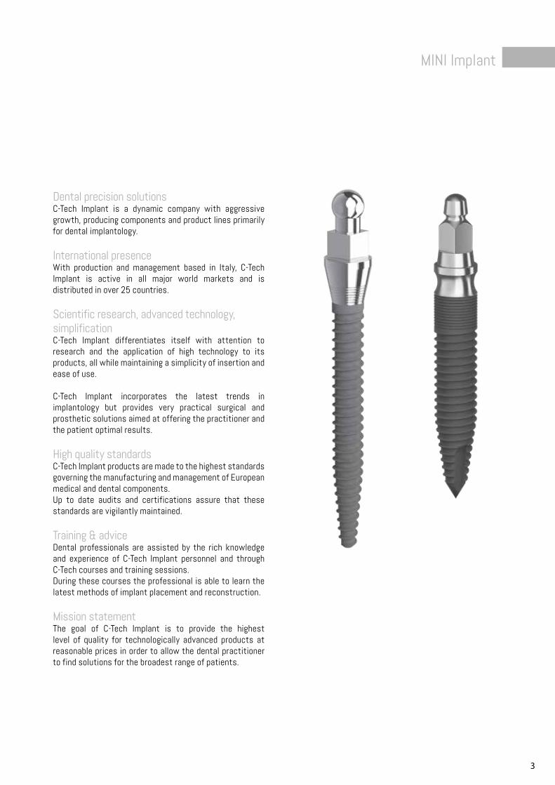
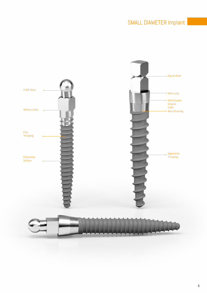
Prosthetic choiceChoice between square or o-ball head depending on fixed or removable applications.
Micro groovingThe lower aspect of the implant collar is endowed with micro grooves to help maintain cortical bone.
Fine threadingThe fine thread SD implants are designed to facilitate the placement in hard bone.
Passivated surfaceThe implant surface is blasted with aluminum oxide and then subjected to progressive etching using citric acid. This surface treatment accelerates the osteointegration process by providing a
greater and more uniform area of contact between bone and implant while favoring an immediate implant load.
Implant bodyThe anatomically shaped implants are produced from medical grade 5 titanium.
Smooth collar The top aspect of every collared implant is smooth so as to better accommodate soft tissue.
Aggressive threadingThe aggressive thread for SD Implants are designed for the added compression and surface area required in soft bone placement.
Collared and non-collared modelsC-tech provides SD models with and without gingival collars, allowing the practitioner to better address cases with differing gingival thicknesses.
5
SMALL DIAMETER Implant
Square Head
O-Ball Head
Micro Grooving
With Smooth GingivalCollar
Without Collar
Fine Threading
Passivated Surface
Aggressive Threading
With collar
6
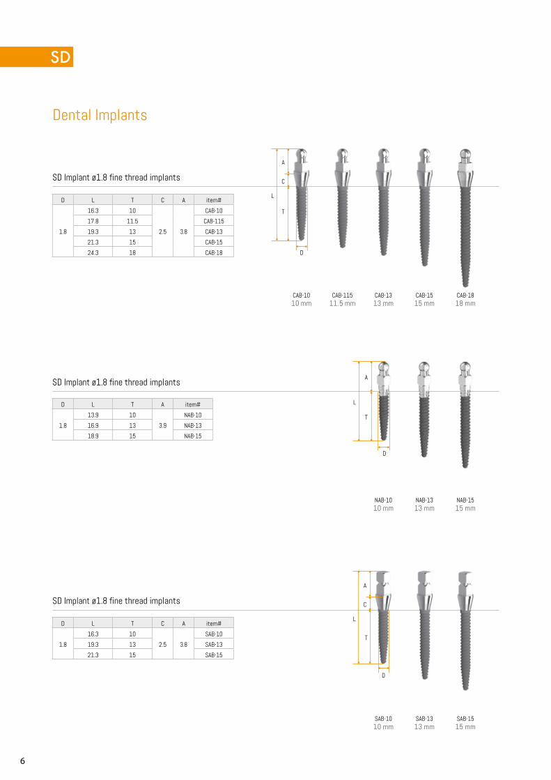
CAB-1010 mm
CAB-11511.5 mm
CAB-1313 mm
CAB-1515 mm
CAB-1818 mm
NAB-1010 mm
NAB-1313 mm
NAB-1515 mm
SAB-1010 mm
SAB-1313 mm
SAB-1515 mm
D
D
D
L
L
L
C
T
C
A
T
T
A
A
Dental Implants
SD Implant ø1.8 fine thread implants
SD Implant ø1.8 fine thread implants
SD Implant ø1.8 fine thread implants
D L T C A item#
1.8
16.3 10
2.5 3.8
SAB-10
19.3 13 SAB-13
21.3 15 SAB-15
D L T A item#
1.8
13.9 10
3.9
NAB-10
16.9 13 NAB-13
18.9 15 NAB-15
D L T C A item#
1.8
16.3 10
2.5 3.8
CAB-10
17.8 11.5 CAB-115
19.3 13 CAB-13
21.3 15 CAB-15
24.3 18 CAB-18
7
SMALL DIAMETER Implant
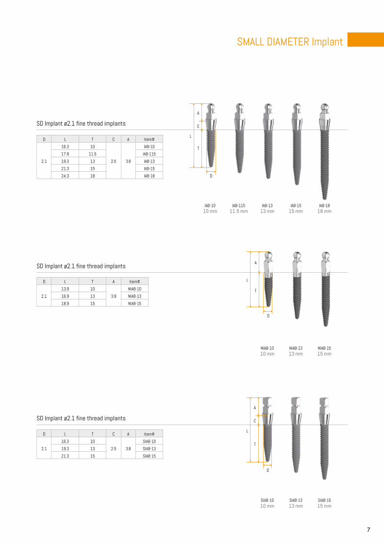
IAB-1010 mm
IAB-11511.5 mm
IAB-1313 mm
IAB-1515 mm
IAB-1818 mm
NIAB-1010 mm
NIAB-1313 mm
NIAB-1515 mm
SIAB-1010 mm
SIAB-1313 mm
SIAB-1515 mm
D
D
D
L
L
L
C
T
C
T
A
T
A
A
SD Implant ø2.1 fine thread implants
SD Implant ø2.1 fine thread implants
SD Implant ø2.1 fine thread implants
D L T C A item#
2.1
16.3 10
2.5 3.8
SIAB-10
19.3 13 SIAB-13
21.3 15 SIAB-15
D L T A item#
2.1
13.9 10
3.9
NIAB-10
16.9 13 NIAB-13
18.9 15 NIAB-15
D L T C A item#
2.1
16.3 10
2.5 3.8
IAB-10
17.8 11.5 IAB-115
19.3 13 IAB-13
21.3 15 IAB-15
24.3 18 IAB-18
8
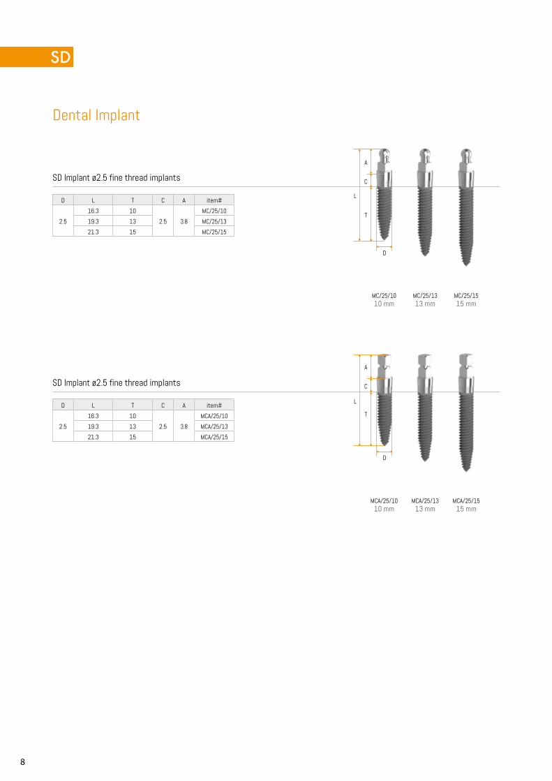
MC/25/1010 mm
MC/25/1313 mm
MC/25/1515 mm
MCA/25/1010 mm
MCA/25/1313 mm
MCA/25/1515 mm
L
L
C
T
C
T
A
A
D
D
Dental Implant
SD Implant ø2.5 fine thread implants
SD Implant ø2.5 fine thread implants
D L T C A item#
2.5
16.3 10
2.5 3.8
MC/25/10
19.3 13 MC/25/13
21.3 15 MC/25/15
D L T C A item#
2.5
16.3 10
2.5 3.8
MCA/25/10
19.3 13 MCA/25/13
21.3 15 MCA/25/15
9
SMALL DIAMETER Implant
MAB-1010 mm
MAB-1313 mm
MAB-1515 mm
MAB-1818 mm
NMAB-1010 mm
NMAB-1313 mm
NMAB-1515 mm
SMAB-1010 mm
SMAB-1313 mm
SMAB-1515 mm
D
D
L
L
L
C
T
C
T
A
T
A
A
D
D
D
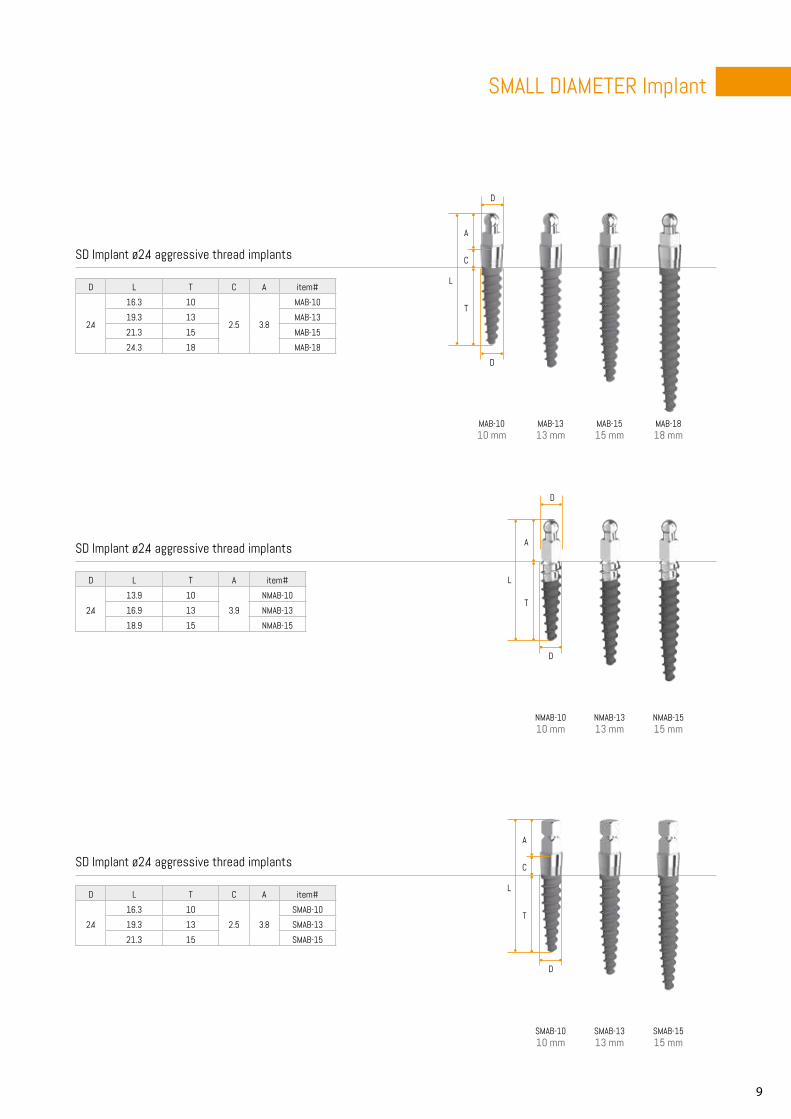
SD Implant ø2.4 aggressive thread implants
SD Implant ø2.4 aggressive thread implants
SD Implant ø2.4 aggressive thread implants
D L T C A item#
2.4
16.3 10
2.5 3.8
SMAB-10
19.3 13 SMAB-13
21.3 15 SMAB-15
D L T A item#
2.4
13.9 10
3.9
NMAB-10
16.9 13 NMAB-13
18.9 15 NMAB-15
D L T C A item#
2.4
16.3 10
2.5 3.8
MAB-10
19.3 13 MAB-13
21.3 15 MAB-15
24.3 18 MAB-18
10
MC-3010
x5
x5
x5
x10
x10
x10
x25
x25
x25
D
D
L
L
L
L
L
D L
4.3 9.4
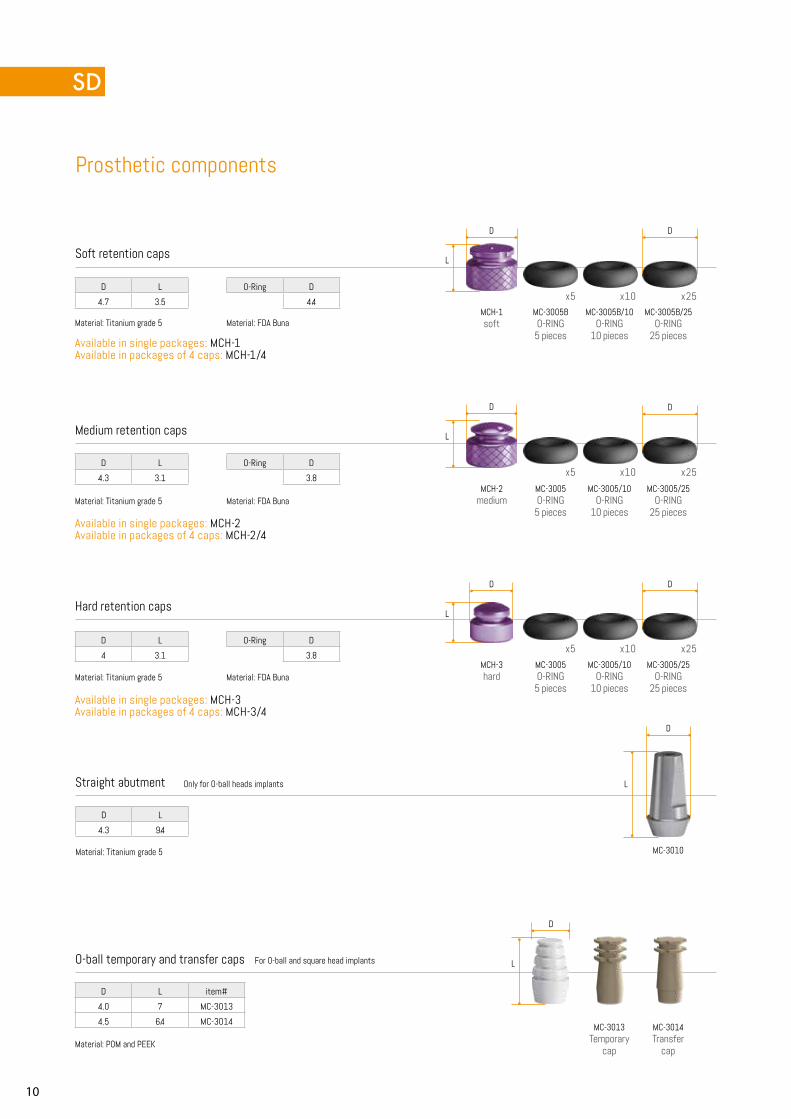
Prosthetic components
Soft retention caps
Medium retention caps
Hard retention caps
MCH-1soft
MC-3005BO-RING
5 pieces
MC-3005B/10O-RING
10 pieces
MC-3005B/25O-RING
25 pieces
MCH-2medium
MC-3005O-RING
5 pieces
MC-3005/10O-RING
10 pieces
MC-3005/25O-RING
25 pieces
MCH-3hard
MC-3005O-RING
5 pieces
MC-3005/10O-RING
10 pieces
MC-3005/25O-RING
25 pieces
Straight abutment Only for O-ball heads implants
D D
D
D
D
D
D L
4.7 3.5
O-Ring D
4.4
O-Ring D
3.8
O-Ring D
3.8
D L
4.3 3.1
D L
4 3.1
Material: Titanium grade 5
Available in single packages: MCH-1 Available in packages of 4 caps: MCH-1/4
Available in single packages: MCH-2 Available in packages of 4 caps: MCH-2/4
Available in single packages: MCH-3 Available in packages of 4 caps: MCH-3/4
Material: Titanium grade 5
Material: Titanium grade 5
Material: FDA Buna
Material: FDA Buna
Material: FDA Buna
Material: Titanium grade 5
D L item#
4.0 7 MC-3013
4.5 6.4 MC-3014
O-ball temporary and transfer caps For O-ball and square head implants
Material: POM and PEEK
MC-3013Temporary
cap
MC-3014Transfer
cap
11
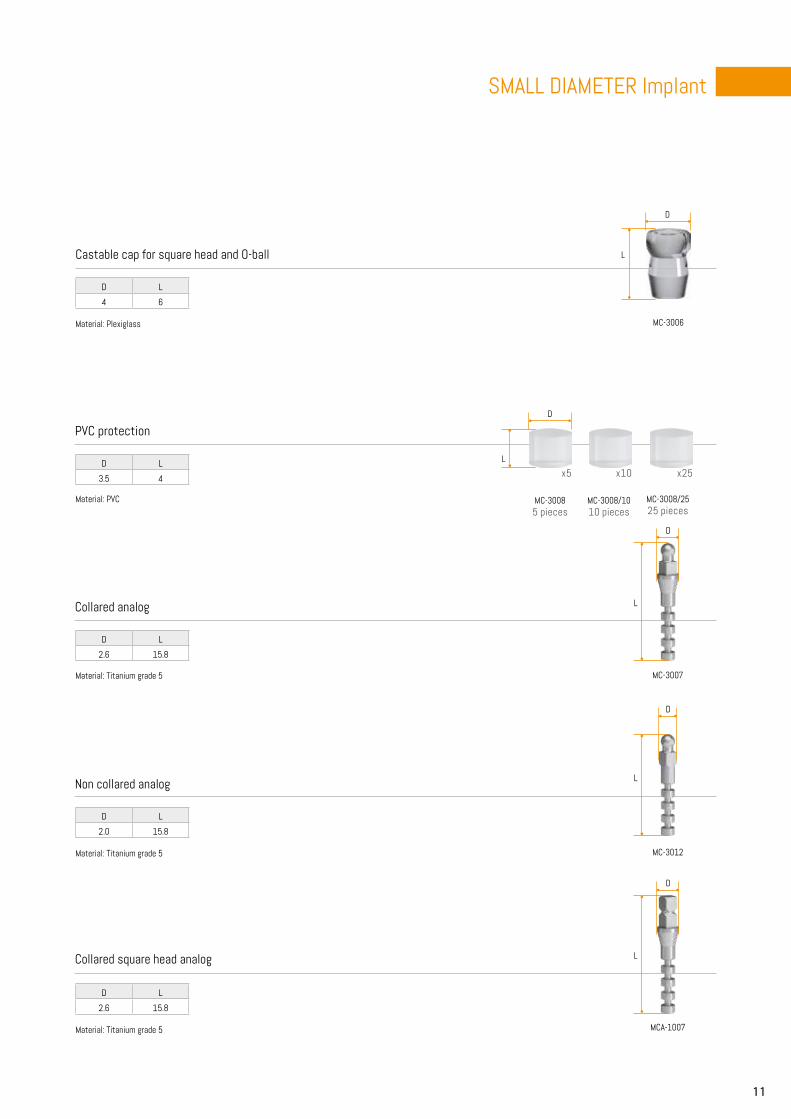
SMALL DIAMETER Implant
MC-3006
MCA-1007
MC-3007
MC-3012
x5 x10 x25
D
D
D
D
D
L
L
L
L
L
D L
2.6 15.8
D L
2.0 15.8
D L
3.5 4
D L
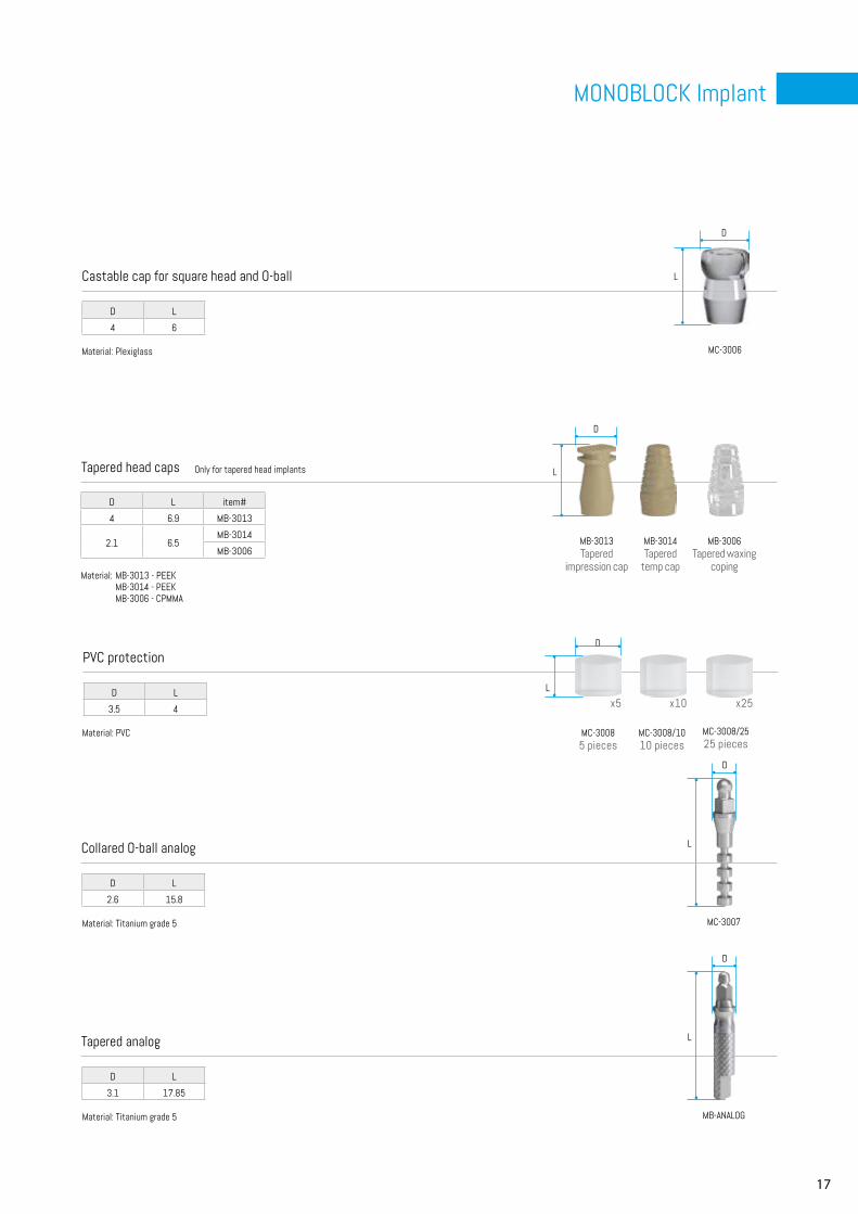
4 6
D L
2.6 15.8
Castable cap for square head and O-ball
Collared square head analog
PVC protection
Collared analog
Non collared analog
MC-30085 pieces
MC-3008/1010 pieces
MC-3008/2525 pieces
Material: Titanium grade 5
Material: Titanium grade 5
Material: Titanium grade 5
Material: PVC
Material: Plexiglass
12
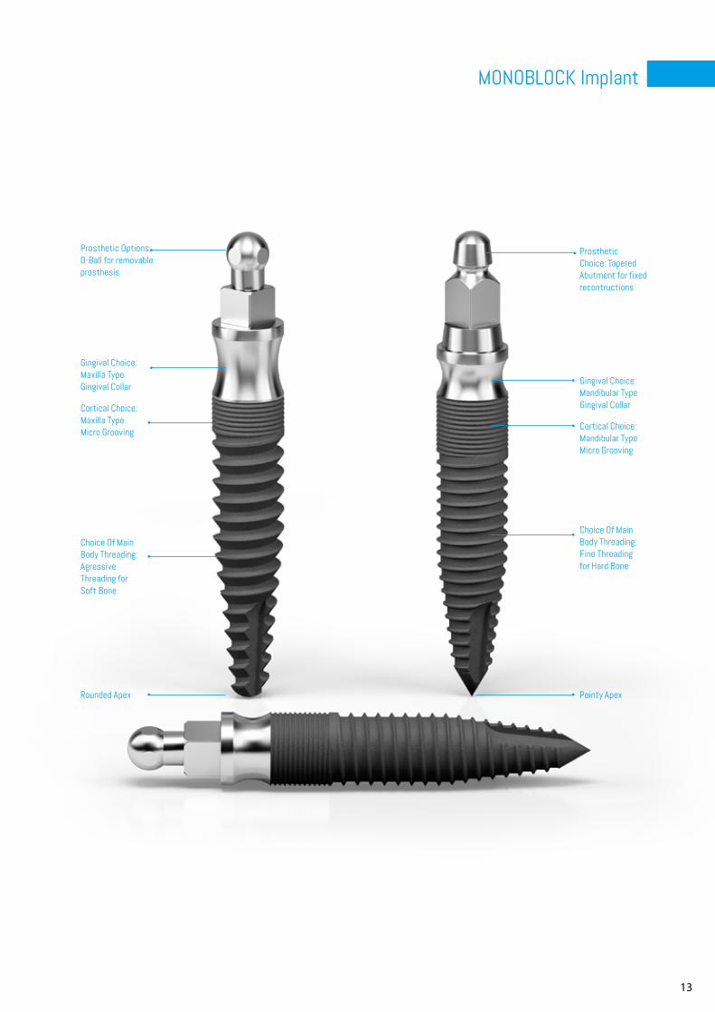
The C-Tech MB, Mono Block Implant, provides 2 different prosthetic options as well as 2 different main body designs to meet the differing requirements of bone and soft tissue encountered in the maxilla and the mandible.
Prosthetic Options Choice between square or O-ball head depending on fixed or removable applications.
Support for Fixed RecontructionsA tapered head with a 4,8mm height above the 3,1mm platform offers and optimal base and structure for the fixed reconstruction.
Gingival Collar MAN-OB/MAN-TAP smooth collar provides the platform switching height to accommodate the average mandibular gingival tissue.
Mandibular Cortical Maintenance Augmented MAN-OB/MAN-TAP micro grooving for the increased cortical height of the mandibular bone.
Low Profile Threading Low profile threading offers surface area yet with the reduced resistance necessary for placement in the D1/D2 bone that can be encountered in the mandible.
Surface TopographyBlasted and acid etched main body surface.
Mandibular Apex Sharp apex to facilitate advancement in D1/D2 bone.
System Compatiblity Choice of tapered and O-ball head prosthetics. O-ball head is compatible with SD, GL, BL and EL O-ball attachments
Augmented Gingival Collar MAX-OB/MAX-TAP smooth collar platform switching fits the thicker maxillary gingival tissue
Maxilla Type Bone Micro Grooving MAX-OB/MAX-TAP micro grooving accommodates the thinner cortical bone that is encountered in the maxilla.
Aggressive Main Body Threading MAX-OB/MAX-TAP main body threading, agressive reverse buttress threads deliver the surface area and stability required by softer maxillary bone
Maxilla Type ApexRounded tip is ideal for the maxilla so as to prevent the possible perforation of the sinus.
MONOBLOCK Implant
13
MONOBLOCK Implant
Prosthetic Choice: Tapered Abutment for fixed recontructions
Prosthetic Options: O-Ball for removable prosthesis
Cortical Choice: Mandibular Type Micro Grooving
Gingival Choice: Mandibular Type Gingival Collar
Gingival Choice: Maxilla Type Gingival Collar
Cortical Choice: Maxilla Type Micro Grooving
Choice Of Main Body Threading: Agressive Threading for Soft Bone
Rounded Apex Pointy Apex
Choice Of Main Body Threading: Fine Threading for Hard Bone
14
MANOB-099 mm
MANOB-1111 mm
MANOB-1313 mm
MANOB-1515 mm
MAXOB-099 mm
MAXOB-1111 mm
MAXOB-1313 mm
MAXOB-1515 mm
MANTAP-099 mm
MANTAP-1111 mm
MANTAP-1313 mm
MANTAP-1515 mm
D
D
D
L
L
L
C
C
C
T
T
T
A
A
A
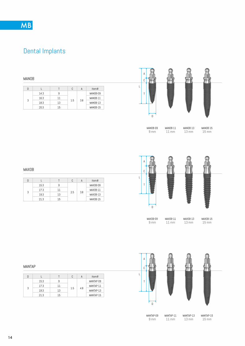
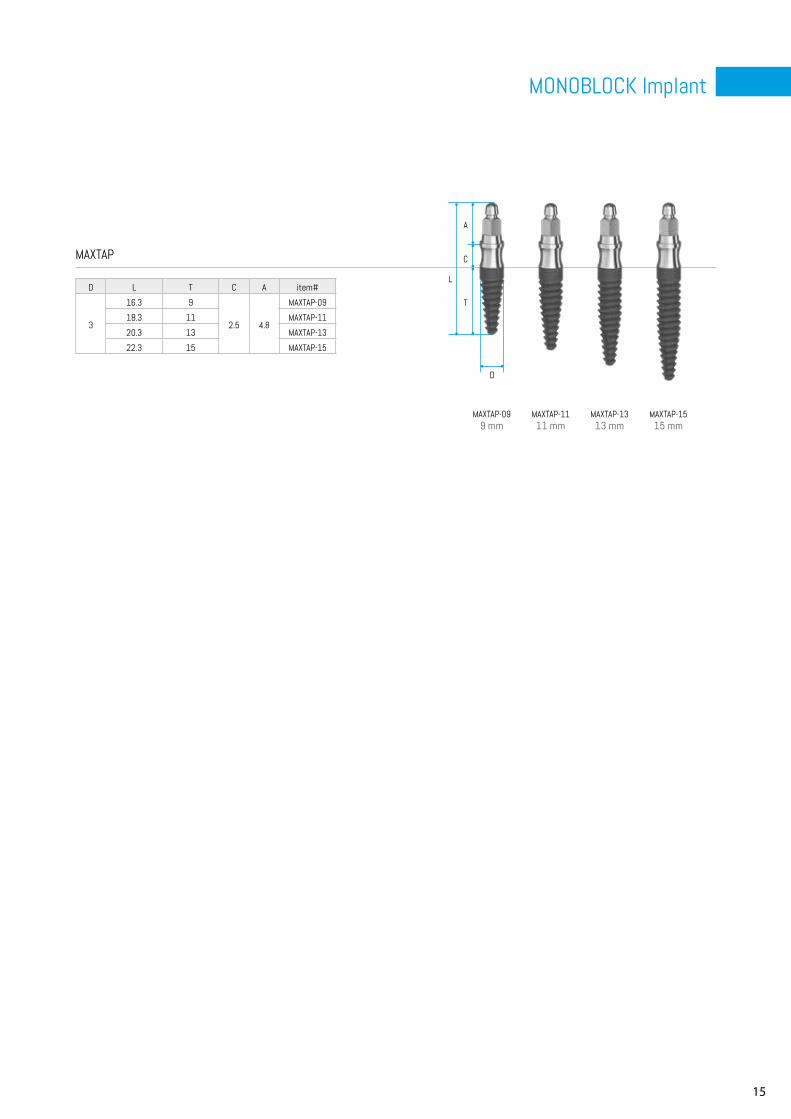
Dental Implants
MANOB
MAXOB
MANTAP
D L T C A item#
3
14.3 9
1.5 3.8
MANOB-09
16.3 11 MANOB-11
18.3 13 MANOB-13
20.3 15 MANOB-15
D L T C A item#
3
15.3 9
2.5 3.8
MAXOB-09
17.3 11 MAXOB-11
19.3 13 MAXOB-13
21.3 15 MAXOB-15
D L T C A item#
3
15.3 9
1.5 4.8
MANTAP-09
17.3 11 MANTAP-11
19.3 13 MANTAP-13
21.3 15 MANTAP-15
15
MONOBLOCK Implant
MAXTAP-099 mm
MAXTAP-1111 mm
MAXTAP-1313 mm
MAXTAP-1515 mm
D
L
C
T
A
MAXTAP
D L T C A item#
3
16.3 9
2.5 4.8
MAXTAP-09
18.3 11 MAXTAP-11
20.3 13 MAXTAP-13
22.3 15 MAXTAP-15
16
D
L
MC-3010
x5
x5
x5
x10
x10
x10
x25
x25
x25
D
L
L
L
L
D L
4.3 9.4
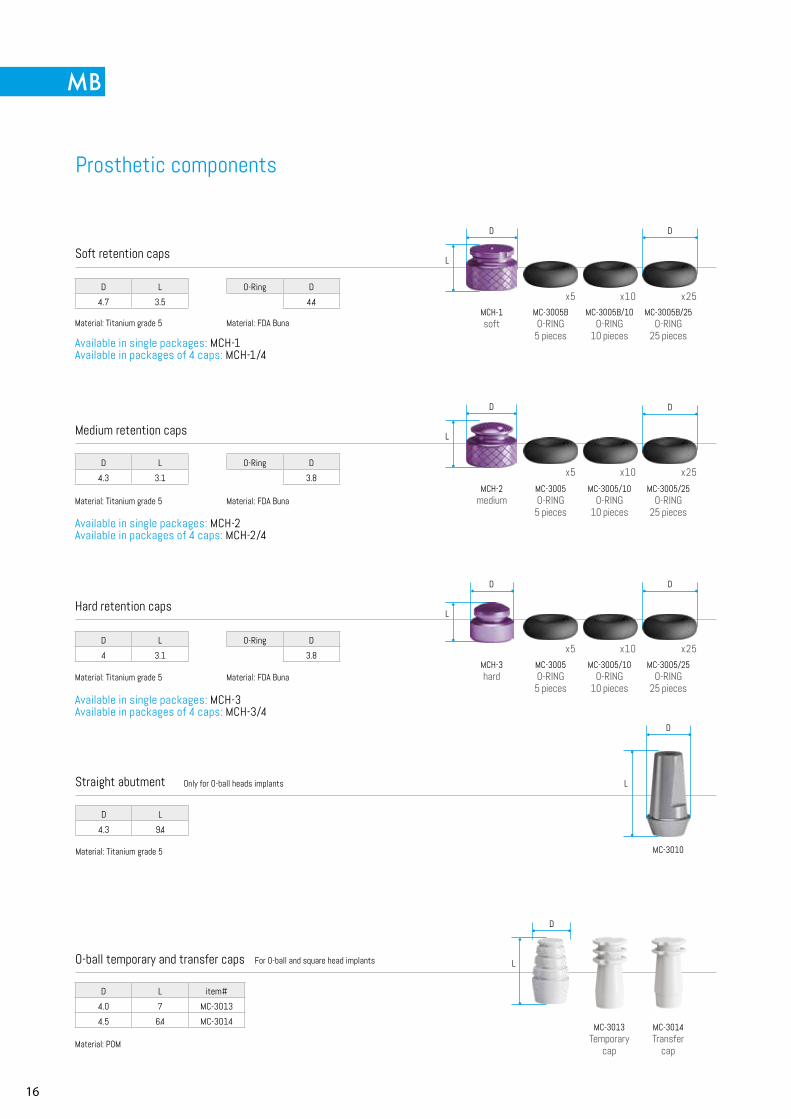
Prosthetic components
O-ball temporary and transfer caps For O-ball and square head implants
Material: POM
D L item#
4.0 7 MC-3013
4.5 6.4 MC-3014 MC-3013Temporary
cap
MC-3014Transfer
cap
MCH-1soft
MC-3005BO-RING
5 pieces
MC-3005B/10O-RING
10 pieces
MC-3005B/25O-RING
25 pieces
MCH-2medium
MC-3005O-RING
5 pieces
MC-3005/10O-RING
10 pieces
MC-3005/25O-RING
25 pieces
MCH-3hard
MC-3005O-RING
5 pieces
MC-3005/10O-RING
10 pieces
MC-3005/25O-RING
25 pieces
Straight abutment Only for O-ball heads implants
D D
D
D
D
D
D L
4.7 3.5
O-Ring D
4.4
O-Ring D
3.8
O-Ring D
3.8
D L
4.3 3.1
D L
4 3.1
Material: Titanium grade 5
Material: Titanium grade 5
Material: Titanium grade 5
Material: FDA Buna
Material: FDA Buna
Material: FDA Buna
Material: Titanium grade 5
Soft retention caps
Medium retention caps
Hard retention caps
Available in single packages: MCH-1 Available in packages of 4 caps: MCH-1/4
Available in single packages: MCH-2 Available in packages of 4 caps: MCH-2/4
Available in single packages: MCH-3 Available in packages of 4 caps: MCH-3/4
17
MONOBLOCK Implant
x5 x10 x25
D
D
D
D
L
L
L
L
D L
2.6 15.8
D L
3.1 17.85
D L
3.5 4
MC-3007
MB-ANALOG
MC-3006
D
L
D L
4 6
Tapered head caps
PVC protection
Collared O-ball analog
Tapered analog
MC-30085 pieces
MC-3008/1010 pieces
MC-3008/2525 pieces
Material: Titanium grade 5
Material: Titanium grade 5
Material: MB-3013 - PEEK MB-3014 - PEEK MB-3006 - CPMMA
Material: PVC
MB-3013Tapered
impression cap
MB-3014Tapered
temp cap
MB-3006Tapered waxing
coping
D L item#
4 6.9 MB-3013
2.1 6.5MB-3014
MB-3006
Castable cap for square head and O-ball
Only for tapered head implants
Material: Plexiglass
18
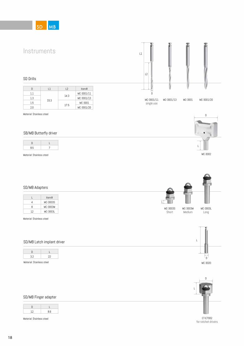
MC-3002
MC-3001/11single use
MC-3001/13 MC-3001 MC-3001/20
D L
12 8.6
D L
3.2 22
D L
8.5 7
D
D
L
L
L
L1
L2
D
MC-3020
L
D
Instruments
SD/MB Finger adapter
SB/MB Butterfly driver
SD/MB Adapters
SD Drills
MC-3003SShort
MC-3003MMedium
MC-3003LLong
Material: Stainless steel
Material: Stainless steel
Material: Stainless steel
Material: Stainless steel
L item#
4 MC-3003S
8 MC-3003M
12 MC-3003L
D L1 L2 item#
1.1
33.3
14.3MC-3001/11
1.3 MC-3001/13
1.517.5
MC-3001
2.0 MC-3001/20
SD/MB Latch implant driver
Material: Stainless steel
CT-E7002for ratchet drivers
19
MINI Implant
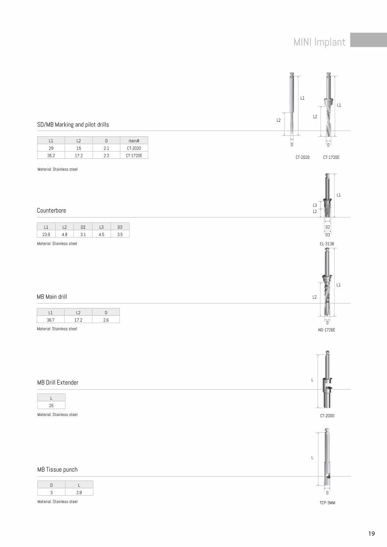
CT-2020 CT-1720E
D D
L2L2
L1L1
L1 L2 D
36.7 17.2 2.6
ND-1726ED
L2
L1
L
25
CT-2000
L
D L
3 2.8
TCP-3MM
L
D
D2
L2L3
L1
L1 L2 D2 L3 D3
23.9 4.8 3.1 4.5 3.5
EL-3138
D3
MB Main drill
Material: Stainless steel
Material: Stainless steel
SD/MB Marking and pilot drills
MB Drill Extender
Material: Stainless steel
MB Tissue punch
Material: Stainless steel
Counterbore
Material: Stainless steel
L1 L2 D item#
29 15 2.1 CT-2020
35.2 17.2 2.3 CT-1720E
20
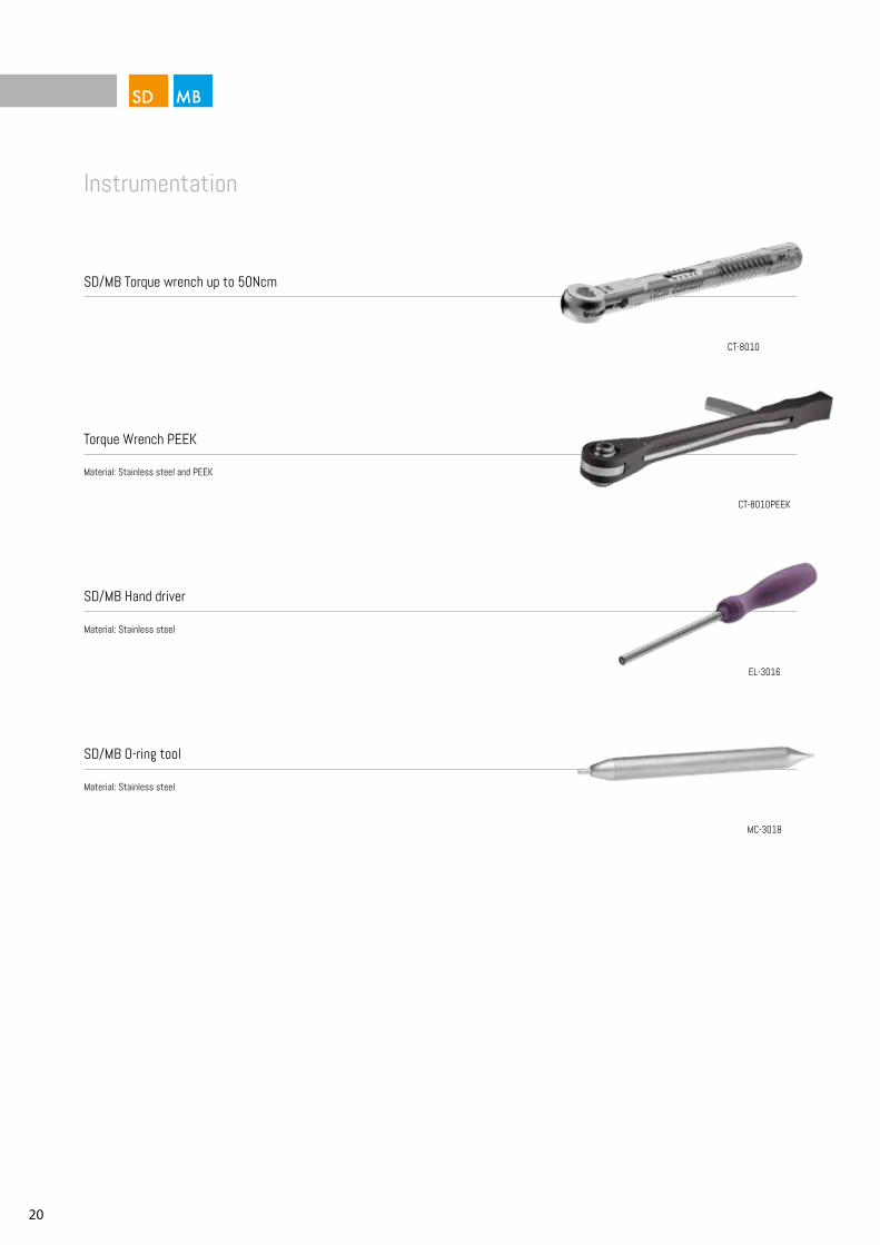
CT-8010
EL-3016
MC-3018
CT-8010PEEK
SD/MB Torque wrench up to 50Ncm
SD/MB Hand driver
Material: Stainless steel
SD/MB O-ring tool
Material: Stainless steel
Instrumentation
Torque Wrench PEEK
Material: Stainless steel and PEEK
21
MINI Implant
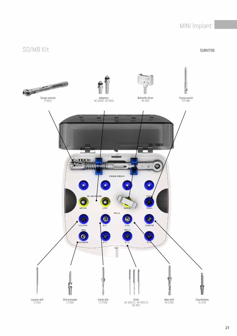
SURKIT05SD/MB Kit
Torque wrenchCT-8010
Butterfly driver MC-3002
Tissue punch TCP-3MM
Adapters MC-3003M - MC-3003L
Locator drillCT-2020
Initial drillCT-1720E
DrillsMC-3001/11 - MC-3001/13
MC-3001
Drill extenderCT-2000
Main drillND-1726E
CounterboreEL-3138
22
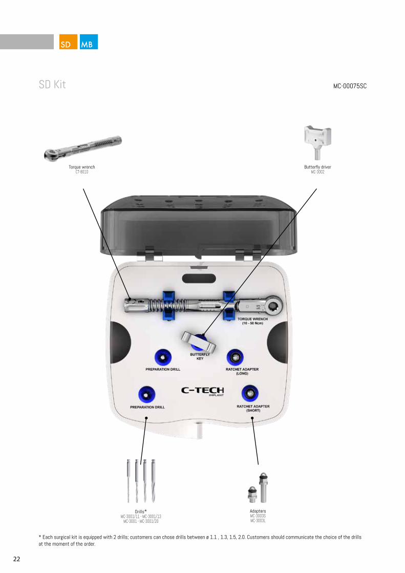
MC-00075SCSD Kit
* Each surgical kit is equipped with 2 drills; customers can chose drills between ø 1.1 , 1.3, 1.5, 2.0. Customers should communicate the choice of the drills at the moment of the order.
Torque wrenchCT-8010
Butterfly driver MC-3002
AdaptersMC-3003SMC-3003L
Drills*MC-3001/11 - MC-3001/13
MC-3001 - MC-3001/20
23
MINI Implant
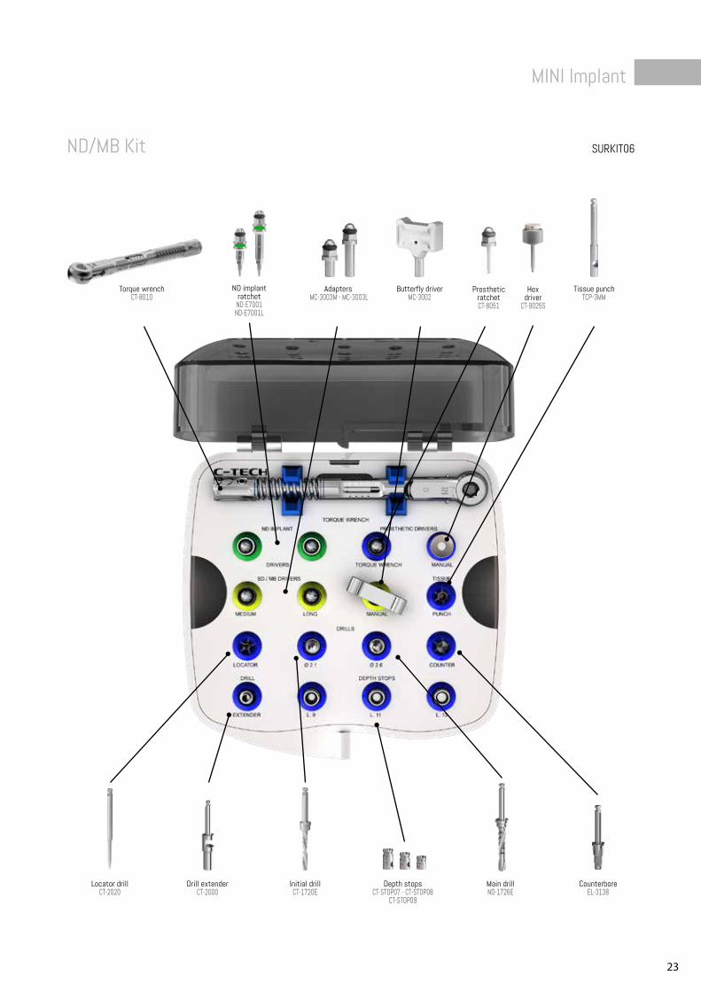
SURKIT06ND/MB Kit
Torque wrenchCT-8010
Butterfly driver MC-3002
Tissue punch TCP-3MM
Adapters MC-3003M - MC-3003L
Locator drillCT-2020
Initial drillCT-1720E
Depth stopsCT-STOP07 - CT-STOP08
CT-STOP09
Drill extenderCT-2000
Main drillND-1726E
ND implant ratchet
ND-E7001 ND-E7001L
Prosthetic ratchetCT-8051
Hex driver
CT-9025S
CounterboreEL-3138
24
1
2
3
4
5
24
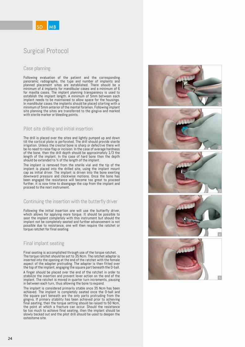
Case planning
Following evaluation of the patient and the corresponding panoramic radiographs, the type and number of implants and planned placement sites are established. There should be a minimum of 4 implants for mandibular cases and a minimum of 6 for maxilla cases. The implant planning transparency is used to establish the implant length. A minimum of 5mm between each implant needs to be maintained to allow space for the housings. In mandibular cases the implants should be placed starting with a minimum of 5mm anterior of the mental foramen. Following implant site planning the sites are transferred to the gingiva and marked with sterile marker or bleeding points.
Pilot site drilling and initial insertion
The drill is placed over the sites and lightly pumped up and down till the cortical plate is perforated. The drill should provide sterile irrigation. Unless the crestal bone is sharp or defective there will be no need to raise flap or incision. In the case of average hardness of the bone, then the drill depth should be approximately 1/3 the length of the implant. In the case of hard bone then the depth should be extended to ¾ of the length of the implant.The implant is removed from the sterile vial and the tip of the implant is placed into the drilled site, using the implant mount cap as initial driver. The implant is driven into the bone exerting downward pressure and clockwise motions. Once the bone has been engaged the resistance will become too great to proceed further, it is now time to disengage the cap from the implant and proceed to the next instrument.
Continuing the insertion with the butterfly driver
Following the initial insertion one will use the butterfly driver, which allows for applying more torque. It should be possible to seat the implant completely with this instrument but should the implant not be completely seated and further advancement is not possible due to resistance, one will then require the ratchet or torque ratchet for final seating.
Final implant seating
Final seating is accomplished through use of the torque ratchet.The torque ratchet should be set to 35 Ncm. The ratchet adapter is inserted into the opening at the end of the ratchet with the female aspect of the adapter protruding. The adapter is then fitted over the top of the implant, engaging the square part beneath the O-ball.A finger should be placed over the end of the ratchet in order to stabilize the insertion and prevent lever action on the end of the implant. The ratchet is moved in quarter turn increments, pausing in between each turn, thus allowing the bone to expand.The implant is considered primarily stable once 35 Ncm has been achieved. The implant is completely seated once the O-ball and the square part beneath are the only parts protruding from the gingiva. If primary stability has been achieved prior to achieving final seating, then the torque setting should be raised to 50 Ncm, the point at which a fracture can occur. Should the resistance be too much to achieve final seating, then the implant should be slowly backed out and the pilot drill should be used to deepen the osteotome site.
Surgical Protocol
25
MINI Implant
1
2
3
4
6 7
98
5
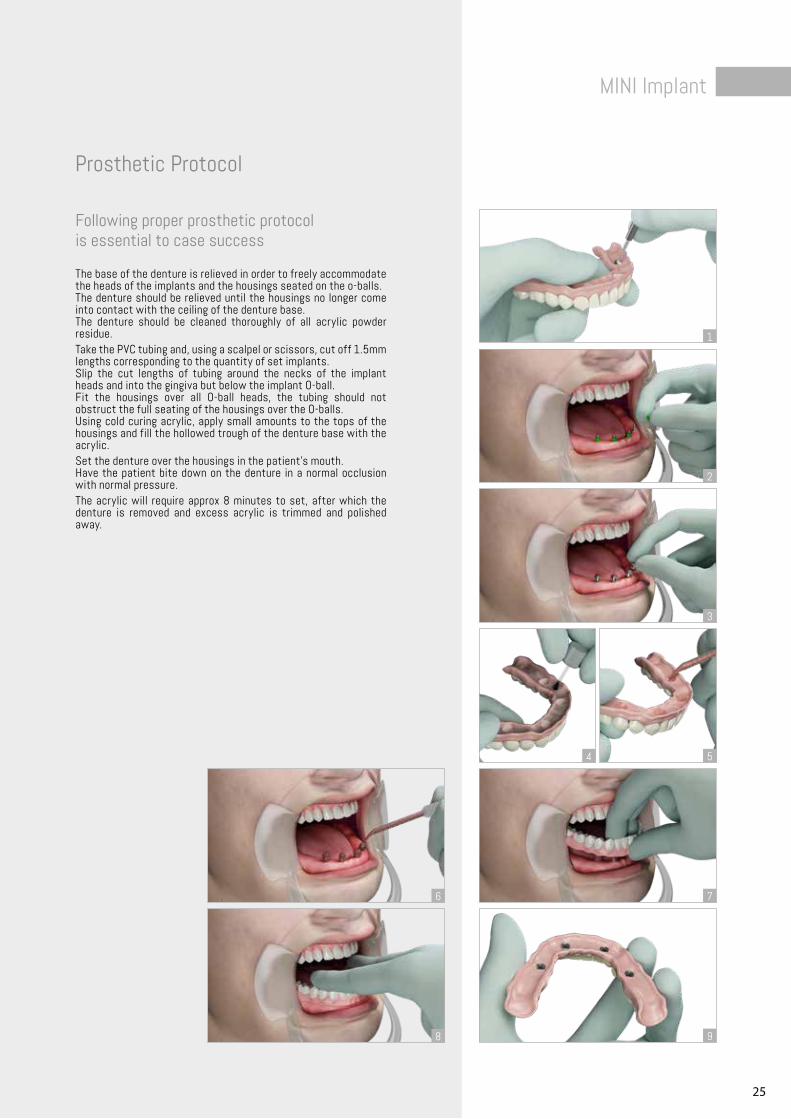
Following proper prosthetic protocolis essential to case success
The base of the denture is relieved in order to freely accommodate the heads of the implants and the housings seated on the o-balls.The denture should be relieved until the housings no longer come into contact with the ceiling of the denture base.The denture should be cleaned thoroughly of all acrylic powder residue.Take the PVC tubing and, using a scalpel or scissors, cut off 1.5mm lengths corresponding to the quantity of set implants.Slip the cut lengths of tubing around the necks of the implant heads and into the gingiva but below the implant O-ball.Fit the housings over all O-ball heads, the tubing should not obstruct the full seating of the housings over the O-balls.Using cold curing acrylic, apply small amounts to the tops of the housings and fill the hollowed trough of the denture base with the acrylic.Set the denture over the housings in the patient’s mouth.Have the patient bite down on the denture in a normal occlusion with normal pressure.The acrylic will require approx 8 minutes to set, after which the denture is removed and excess acrylic is trimmed and polished away.
Prosthetic Protocol
26
ø1.8
L. 10 mmL. 11,5 mmL. 13 mmL. 15 mm
2,5 mm
3,8 mm
ø2.1
L. 10 mmL. 11,5 mmL. 13 mmL. 15 mm
2,5 mm
3,8 mm
ø2.5
L. 10 mmL. 13 mmL. 15 mm
2,5 mm
3,8 mm
ø2.4
L. 10 mmL. 13 mmL. 15 mm
2,5 mm
3,8 mm
100
- 750
rpm
1/3
Leng
th o
f im
plan
t
Inse
rtion
Tor
que:
35
- 45
ncm
Inse
rtion
Tor
que:
35
- 45
ncm
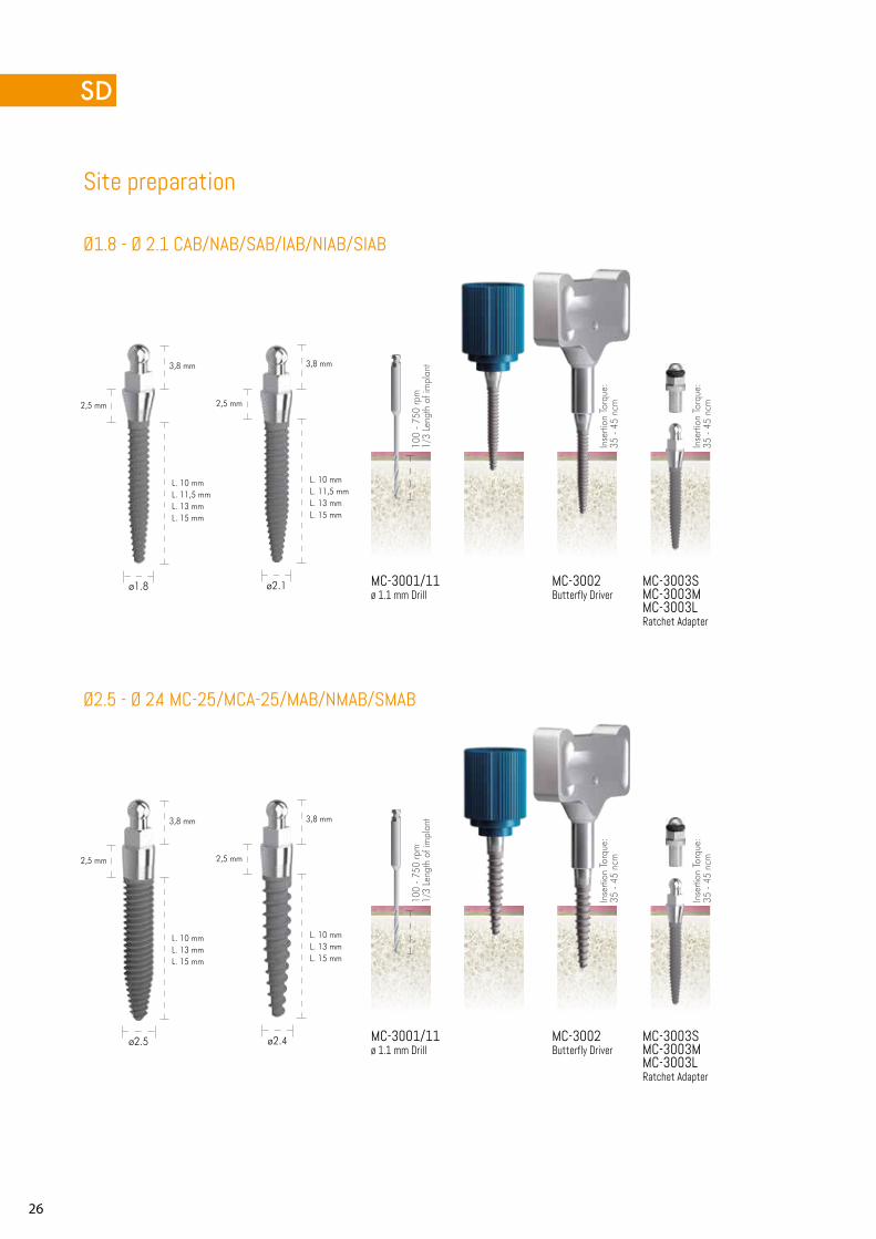
Ø1.8 - Ø 2.1 CAB/NAB/SAB/IAB/NIAB/SIAB
Ø2.5 - Ø 2.4 MC-25/MCA-25/MAB/NMAB/SMAB
MC-3001/11ø 1.1 mm Drill
MC-3002Butterfly Driver
MC-3003SMC-3003MMC-3003LRatchet Adapter
MC-3001/11ø 1.1 mm Drill
MC-3002Butterfly Driver
MC-3003SMC-3003MMC-3003LRatchet Adapter
Site preparation
Inse
rtion
Tor
que:
35
- 45
ncm
Inse
rtion
Tor
que:
35
- 45
ncm
100
- 750
rpm
1/3
Leng
th o
f im
plan
t
27
SMALL DIAMETER Implant
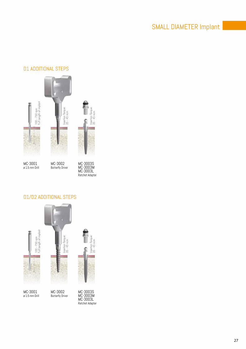
MC-3001ø 1.5 mm Drill
MC-3002Butterfly Driver
MC-3003SMC-3003MMC-3003LRatchet Adapter
MC-3001ø 1.5 mm Drill
MC-3002Butterfly Driver
MC-3003SMC-3003MMC-3003LRatchet Adapter
100
- 750
rpm
Full
Leng
th o
f im
plan
t
Inse
rtion
Tor
que:
35
- 45
ncm
Inse
rtion
Tor
que:
35
- 45
ncm
D1 ADDITIONAL STEPS
D1/D2 ADDITIONAL STEPS
100
- 750
rpm
Full
Leng
th o
f im
plan
t
Inse
rtion
Tor
que:
35
- 45
ncm
Inse
rtion
Tor
que:
35
- 45
ncm
28
4 mm
4 mm
9mm11mm13mm15mm
9mm11mm13mm15mm
3.8mm
1.5mm1.5mmø3.0ø3.0
ø3.0
4.8mm
2.3mm
ø3.2
ø3.0
ø3.0
ø3.0
ø3.0
9mm11mm13mm15mm
9mm11mm13mm15mm
3.8mm
2.5mm2.5mm
ø3.0ø3.0
ø3.0
4.8mm
2.3mm
ø3.2
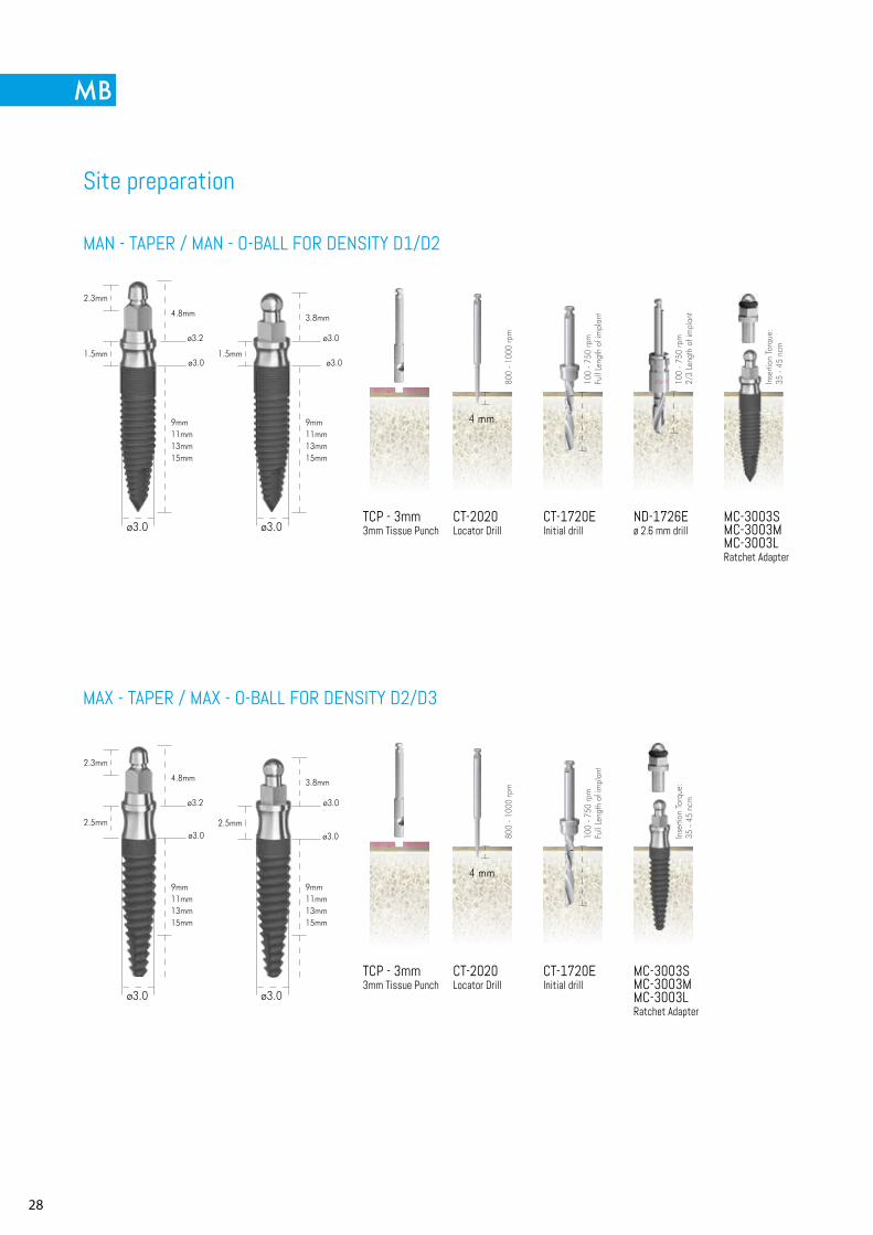
MAN - TAPER / MAN - O-BALL FOR DENSITY D1/D2
MAX - TAPER / MAX - O-BALL FOR DENSITY D2/D3
TCP - 3mm3mm Tissue Punch
CT-2020Locator Drill
CT-1720EInitial drill
ND-1726Eø 2.6 mm drill
MC-3003SMC-3003MMC-3003LRatchet Adapter
TCP - 3mm3mm Tissue Punch
CT-2020Locator Drill
CT-1720EInitial drill
MC-3003SMC-3003MMC-3003LRatchet Adapter
800
- 100
0 rp
m80
0 - 1
000
rpm
100
- 750
rpm
Full
Leng
th o
f im
plan
t10
0 - 7
50 rp
mFu
ll Le
ngth
of i
mpl
ant
100
- 750
rpm
2/3
Leng
th o
f im
plan
t
Inse
rtion
Tor
que:
35
- 45
ncm
Inse
rtion
Tor
que:
35
- 45
ncm
Site preparation
MONOBLOCK Implant
29
7.5 mm
9.5 mm
13.5 mm
11.5 mm
15.5 mm
-0.4 mm
7 mm
9 mm
13 mm
11 mm
15 mm
0 mm
MONOBLOCK Implant
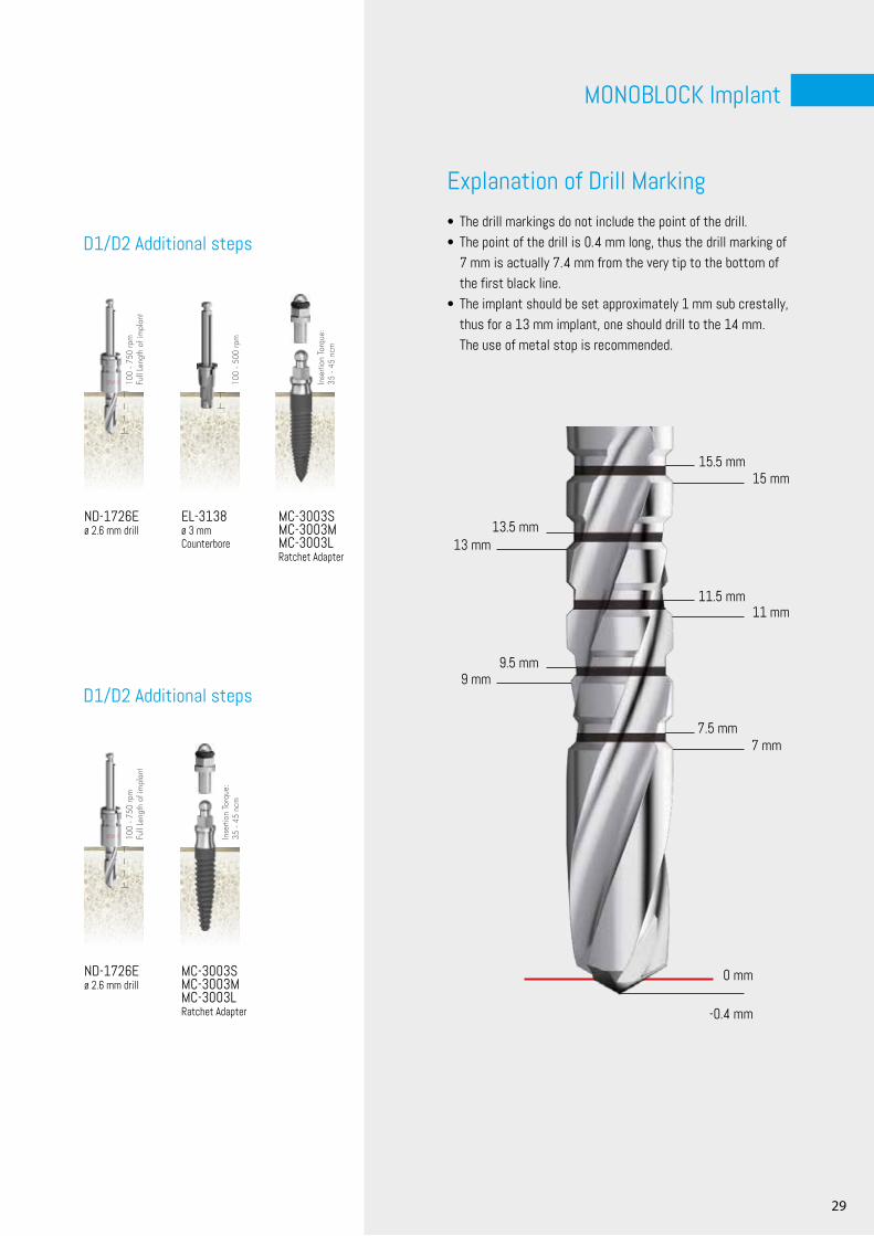
ND-1726Eø 2.6 mm drill
EL-3138ø 3 mm Counterbore
MC-3003SMC-3003MMC-3003LRatchet Adapter
ND-1726Eø 2.6 mm drill
MC-3003SMC-3003MMC-3003LRatchet Adapter
100
- 750
rpm
Full
Leng
th o
f im
plan
t10
0 - 7
50 rp
mFu
ll Le
ngth
of i
mpl
ant
100
- 500
rpm
Inse
rtion
Tor
que:
35
- 45
ncm
Inse
rtion
Tor
que:
35
- 45
ncm
D1/D2 Additional steps
D1/D2 Additional steps
Explanation of Drill Marking• The drill markings do not include the point of the drill.• The point of the drill is 0.4 mm long, thus the drill marking of
7 mm is actually 7.4 mm from the very tip to the bottom of the first black line.
• The implant should be set approximately 1 mm sub crestally, thus for a 13 mm implant, one should drill to the 14 mm. The use of metal stop is recommended.
30

31
MINI Implant
Via Cesare Battisti n. 2 - 40123, Bologna - ITALY Tel. +39 051 6661817 - Fax +39 051 6667071www.c-tech-implant.com - [email protected] Facebook Instagram Linkedinc-tech-implant.com
Go to Follow us
English version
REV.0
2/06
-201
9


