OPERATION AND MAINTENANCE MANUAL WITHILLUSTRATED PARTS LIST
SMALL MODULAR DEICER
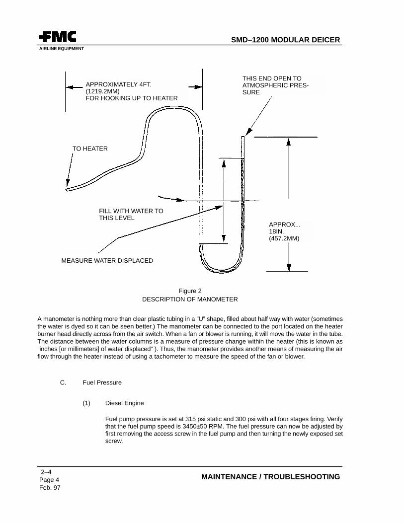
FEB. 1997
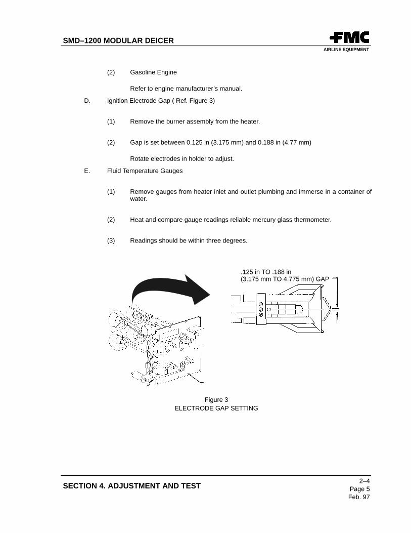
SMD–1200 MODULAR DEICERAIRLINE EQUIPMENT
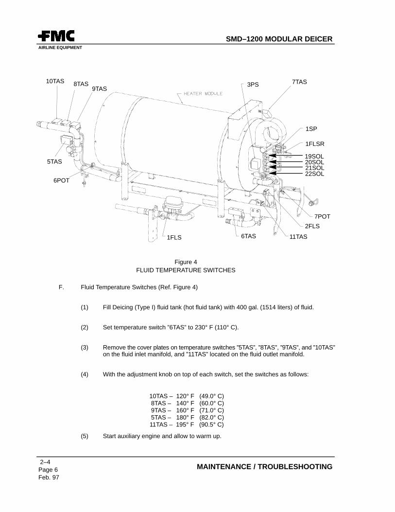
SMD–1200 MODULAR DEICER
OPERATION MAINTENANCE AND ILLUSTRATED PARTS LIST
FOR USE WITH SERIAL NUMBER SM1200OV4DPMONOV. 1998UNIT 047
Model
SMD–1200
MANUFACTURED BY
FMC CORPORATION APSDAIRLINE EQUIPMENT
7300 PRESIDENTS DRIVEORLANDO, FLORIDA 32809
TELEPHONE: (407) 851–3377FAX: (407) 850–4221
SMD–1200 MODULAR DEICERAIRLINE EQUIPMENT
CONFIDENTIAL
THIS MANUAL CONTAINS CONFIDENTIAL AND PROPRIETARY INFORMATION OF THE AIRPORTPRODUCTS AND SYSTEMS DIVISION OF FMC CORPORATION, AND CANNOT BE DUPLICATED, USEDOR DISCLOSED IN WHOLE OR IN PART, EXCEPT WITH THE EXPRESS WRITTEN PERSMISSION OF FMCCORPORATION.
� 1995, 1996, 1997
FMC, all rights reserved as an unpublished work.
FMC CorporationAirport Products & Systems Division7300 Presidents DriveOrlando, Florida 32809USA
FMC CorporationCarretera de Barcelona Km.34.400Alcala de HenaresMadrid, Spain
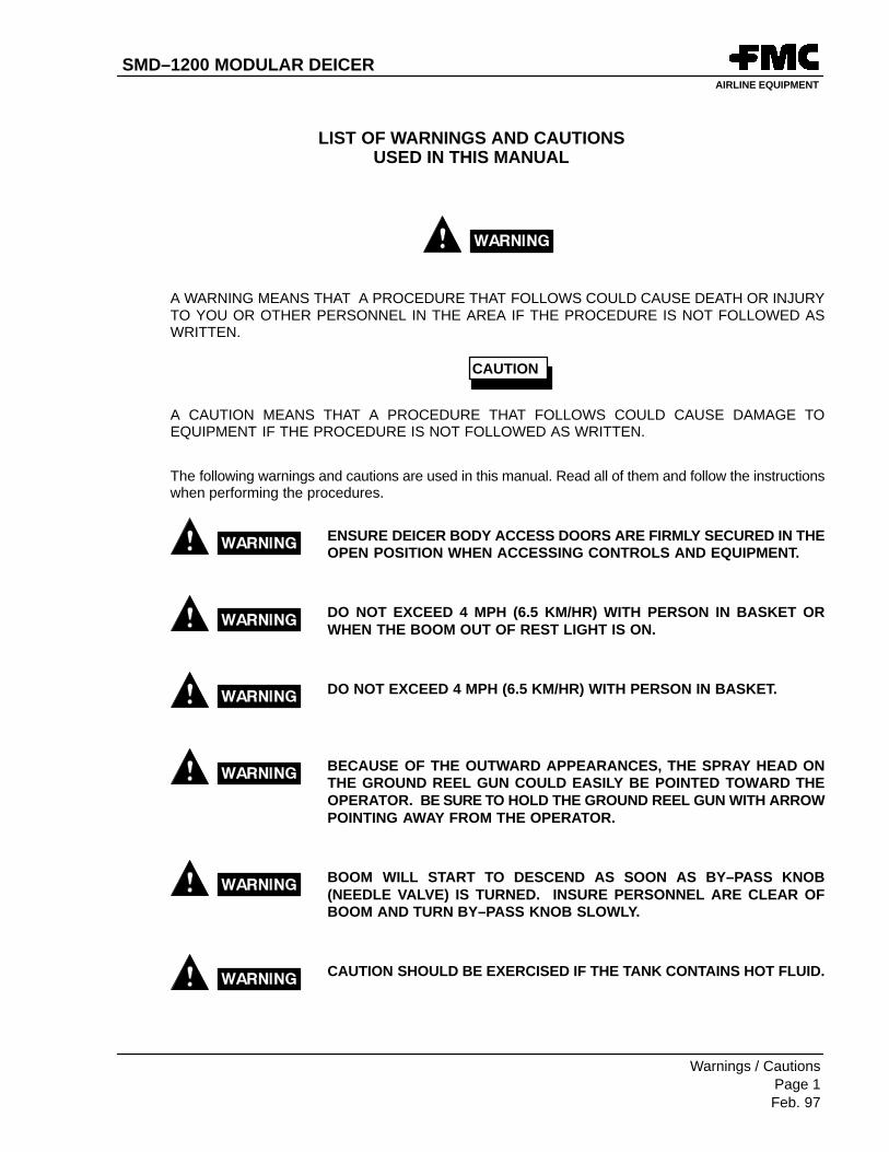
A WARNING MEANS THAT A PROCEDURE THAT FOLLOWS COULD CAUSE DEATH OR INJURYTO YOU OR OTHER PERSONNEL IN THE AREA IF THE PROCEDURE IS NOT FOLLOWED ASWRITTEN.
A CAUTION MEANS THAT A PROCEDURE THAT FOLLOWS COULD CAUSE DAMAGE TOEQUIPMENT IF THE PROCEDURE IS NOT FOLLOWED AS WRITTEN.
The following warnings and cautions are used in this manual. Read all of them and follow the instructionswhen performing the procedures.
ENSURE DEICER BODY ACCESS DOORS ARE FIRMLY SECURED IN THEOPEN POSITION WHEN ACCESSING CONTROLS AND EQUIPMENT.
DO NOT EXCEED 4 MPH (6.5 KM/HR) WITH PERSON IN BASKET ORWHEN THE BOOM OUT OF REST LIGHT IS ON.
DO NOT EXCEED 4 MPH (6.5 KM/HR) WITH PERSON IN BASKET.
BECAUSE OF THE OUTWARD APPEARANCES, THE SPRAY HEAD ONTHE GROUND REEL GUN COULD EASILY BE POINTED TOWARD THEOPERATOR. BE SURE TO HOLD THE GROUND REEL GUN WITH ARROWPOINTING AWAY FROM THE OPERATOR.
BOOM WILL START TO DESCEND AS SOON AS BY–PASS KNOB(NEEDLE VALVE) IS TURNED. INSURE PERSONNEL ARE CLEAR OFBOOM AND TURN BY–PASS KNOB SLOWLY.
CAUTION SHOULD BE EXERCISED IF THE TANK CONTAINS HOT FLUID.
CAUTION
SMD–1200 MODULAR DEICERAIRLINE EQUIPMENT
Warnings / CautionsPage 2Feb. 97
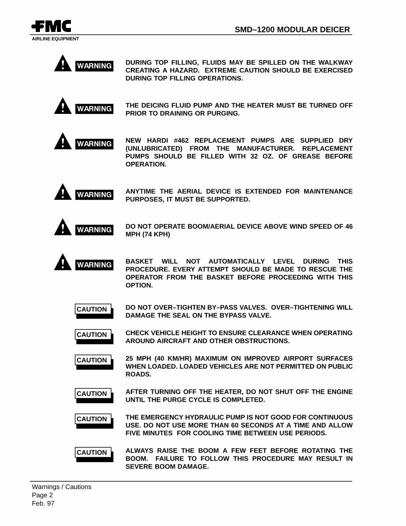
DURING TOP FILLING, FLUIDS MAY BE SPILLED ON THE WALKWAYCREATING A HAZARD. EXTREME CAUTION SHOULD BE EXERCISEDDURING TOP FILLING OPERATIONS.
THE DEICING FLUID PUMP AND THE HEATER MUST BE TURNED OFFPRIOR TO DRAINING OR PURGING.
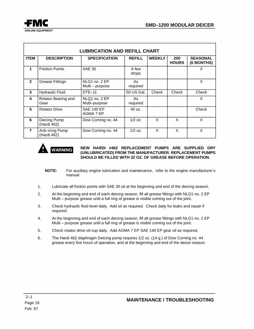
NEW HARDI #462 REPLACEMENT PUMPS ARE SUPPLIED DRY(UNLUBRICATED) FROM THE MANUFACTURER. REPLACEMENTPUMPS SHOULD BE FILLED WITH 32 OZ. OF GREASE BEFOREOPERATION.
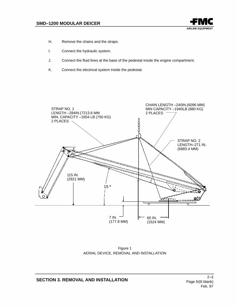
ANYTIME THE AERIAL DEVICE IS EXTENDED FOR MAINTENANCEPURPOSES, IT MUST BE SUPPORTED.
DO NOT OPERATE BOOM/AERIAL DEVICE ABOVE WIND SPEED OF 46MPH (74 KPH)
BASKET WILL NOT AUTOMATICALLY LEVEL DURING THISPROCEDURE. EVERY ATTEMPT SHOULD BE MADE TO RESCUE THEOPERATOR FROM THE BASKET BEFORE PROCEEDING WITH THISOPTION.
DO NOT OVER–TIGHTEN BY–PASS VALVES. OVER–TIGHTENING WILLDAMAGE THE SEAL ON THE BYPASS VALVE.
CHECK VEHICLE HEIGHT TO ENSURE CLEARANCE WHEN OPERATINGAROUND AIRCRAFT AND OTHER OBSTRUCTIONS.
25 MPH (40 KM/HR) MAXIMUM ON IMPROVED AIRPORT SURFACESWHEN LOADED. LOADED VEHICLES ARE NOT PERMITTED ON PUBLICROADS.
AFTER TURNING OFF THE HEATER, DO NOT SHUT OFF THE ENGINEUNTIL THE PURGE CYCLE IS COMPLETED.
THE EMERGENCY HYDRAULIC PUMP IS NOT GOOD FOR CONTINUOUSUSE. DO NOT USE MORE THAN 60 SECONDS AT A TIME AND ALLOWFIVE MINUTES FOR COOLING TIME BETWEEN USE PERIODS.
ALWAYS RAISE THE BOOM A FEW FEET BEFORE ROTATING THEBOOM. FAILURE TO FOLLOW THIS PROCEDURE MAY RESULT INSEVERE BOOM DAMAGE.
CAUTION
CAUTION
CAUTION
CAUTION
CAUTION
CAUTION
SMD–1200 MODULAR DEICERAIRLINE EQUIPMENT
Warnings / CautionsPage 3/(4 blank)
Feb. 97
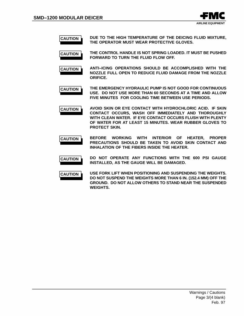
DUE TO THE HIGH TEMPERATURE OF THE DEICING FLUID MIXTURE,THE OPERATOR MUST WEAR PROTECTIVE GLOVES.
THE CONTROL HANDLE IS NOT SPRING LOADED. IT MUST BE PUSHEDFORWARD TO TURN THE FLUID FLOW OFF.
ANTI–ICING OPERATIONS SHOULD BE ACCOMPLISHED WITH THENOZZLE FULL OPEN TO REDUCE FLUID DAMAGE FROM THE NOZZLEORIFICE.
THE EMERGENCY HYDRAULIC PUMP IS NOT GOOD FOR CONTINUOUSUSE. DO NOT USE MORE THAN 60 SECONDS AT A TIME AND ALLOWFIVE MINUTES FOR COOLING TIME BETWEEN USE PERIODS.
AVOID SKIN OR EYE CONTACT WITH HYDROCHLORIC ACID. IF SKINCONTACT OCCURS, WASH OFF IMMEDIATELY AND THOROUGHLYWITH CLEAN WATER. IF EYE CONTACT OCCURS FLUSH WITH PLENTYOF WATER FOR AT LEAST 15 MINUTES. WEAR RUBBER GLOVES TOPROTECT SKIN.
BEFORE WORKING WITH INTERIOR OF HEATER, PROPERPRECAUTIONS SHOULD BE TAKEN TO AVOID SKIN CONTACT ANDINHALATION OF THE FIBERS INSIDE THE HEATER.
DO NOT OPERATE ANY FUNCTIONS WITH THE 600 PSI GAUGEINSTALLED, AS THE GAUGE WILL BE DAMAGED.
USE FORK LIFT WHEN POSITIONING AND SUSPENDING THE WEIGHTS.DO NOT SUSPEND THE WEIGHTS MORE THAN 6 IN. (152.4 MM) OFF THEGROUND. DO NOT ALLOW OTHERS TO STAND NEAR THE SUSPENDEDWEIGHTS.
CAUTION
CAUTION
CAUTION
CAUTION
CAUTION
CAUTION
CAUTION
CAUTION
SMD–1200 MODULAR DEICERAIRLINE EQUIPMENT
1–1Page 1Feb. 97
GENERAL INFORMATION
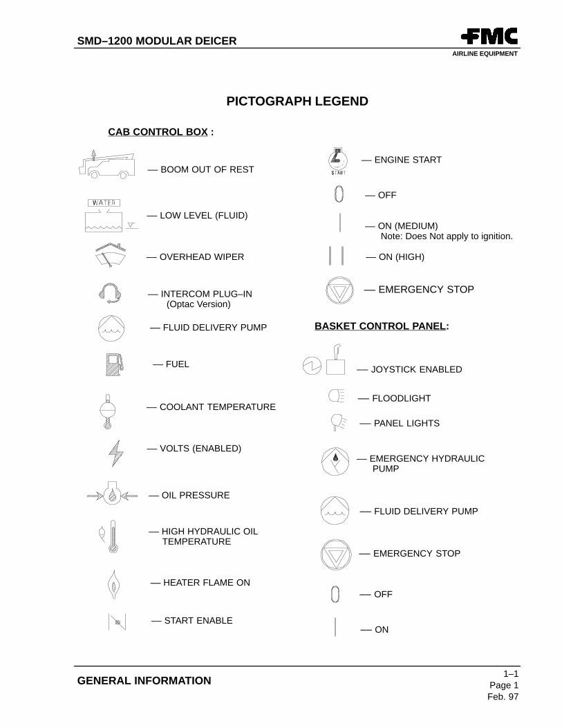
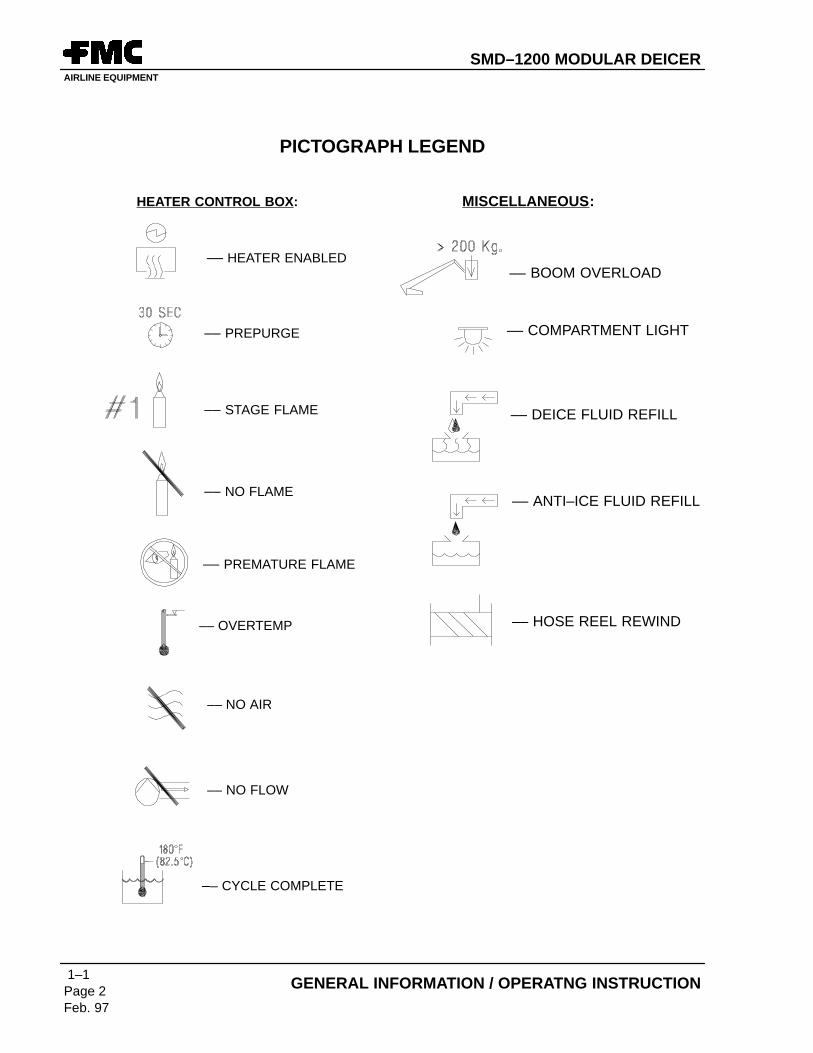
PICTOGRAPH LEGEND
–– BOOM OUT OF REST
–– LOW LEVEL (FLUID)
–– OVERHEAD WIPER
–– INTERCOM PLUG–IN (Optac Version)
–– FLUID DELIVERY PUMP
–– FUEL
–– COOLANT TEMPERATURE
–– VOLTS (ENABLED)
–– OIL PRESSURE
–– HIGH HYDRAULIC OIL TEMPERATURE
–– HEATER FLAME ON
CAB CONTROL BOX :
–– START ENABLE
–– ENGINE START
–– OFF
–– ON (MEDIUM) Note: Does Not apply to ignition.
–– JOYSTICK ENABLED
–– FLOODLIGHT
–– EMERGENCY HYDRAULIC PUMP
–– FLUID DELIVERY PUMP
–– EMERGENCY STOP
–– PANEL LIGHTS
–– OFF
–– ON
BASKET CONTROL PANEL:
–– ON (HIGH)
–– EMERGENCY STOP
SMD–1200 MODULAR DEICERAIRLINE EQUIPMENT
1–1Page 2Feb. 97
GENERAL INFORMATION / OPERATNG INSTRUCTION
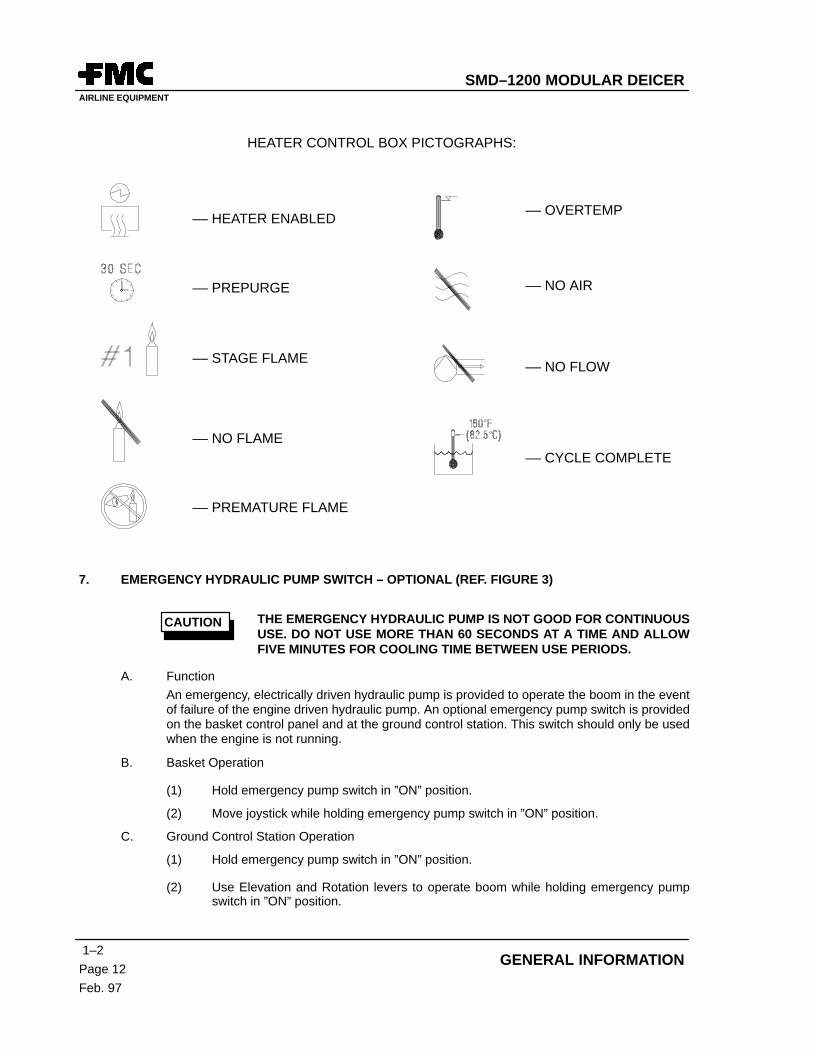
PICTOGRAPH LEGEND
–– NO AIR
–– NO FLOW
–– CYCLE COMPLETE
–– STAGE FLAME
–– HEATER ENABLED
–– PREPURGE
–– NO FLAME
–– PREMATURE FLAME
–– OVERTEMP
MISCELLANEOUS:
–– BOOM OVERLOAD
–– COMPARTMENT LIGHT
–– DEICE FLUID REFILL
–– ANTI–ICE FLUID REFILL
–– HOSE REEL REWIND
HEATER CONTROL BOX:
SMD–1200 MODULAR DEICERAIRLINE EQUIPMENT
ContentsPage 1/(2 blank)
Feb. 97
TABLE OF CONTENTS
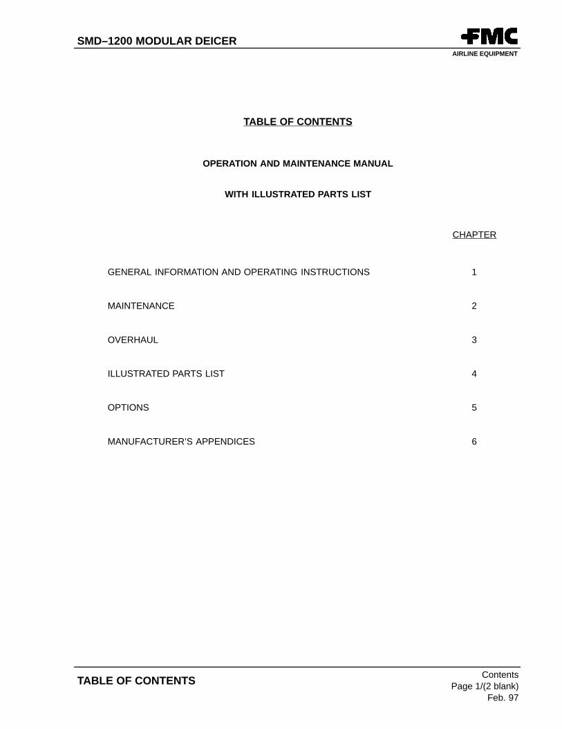
TABLE OF CONTENTS
OPERATION AND MAINTENANCE MANUAL
WITH ILLUSTRATED PARTS LIST
CHAPTER
GENERAL INFORMATION AND OPERATING INSTRUCTIONS 1
MAINTENANCE 2
OVERHAUL 3
ILLUSTRATED PARTS LIST 4
OPTIONS 5
MANUFACTURER’S APPENDICES 6
SMD–1200 MODULAR DEICERAIRLINE EQUIPMENT
1–ContentsPage 1Feb. 97
Chapter 1. GENERAL INFORMATION AND OPERATING INSTRUCTION
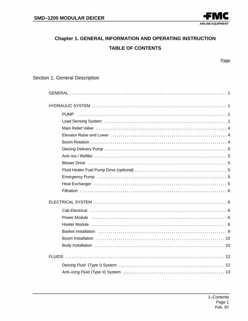
CHAPTER 1. GENERAL INFORMATION AND OPERATING INSTRUCTIONS
Section 1. General Description
1. GENERAL
The Modular Deicer provides mobile deicing and anti–icing for aircraft of all sizes. It is designed to be easilyadaptable to each customer’s specific needs.
The unit can be adapted for use on various chassis used world wide. This adaptability includes a variety of tankcapacities and deice and anti–ice configurations. The various configurations are capable of handling a widevariety of fluids currently in use for deicing and anti–icing. The unit can also be adapted to use many different typesof power modules using various types of fuels.
The controls for operating the Modular Deicer systems, including the power module, are located on a control panelin the truck cab.
An intercom is included in the Modular Deicer for communication between the cab and the basket.
The Modular Deicer has built–in safety features to prevent damage to the unit as well as the operator. All safetyprecautions and warnings should be followed as prescribed in this manual as well as on the truck itself.
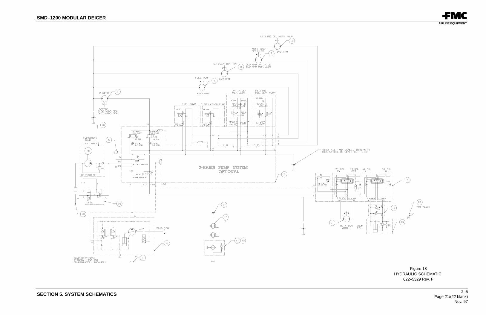
2. HYDRAULIC SYSTEM
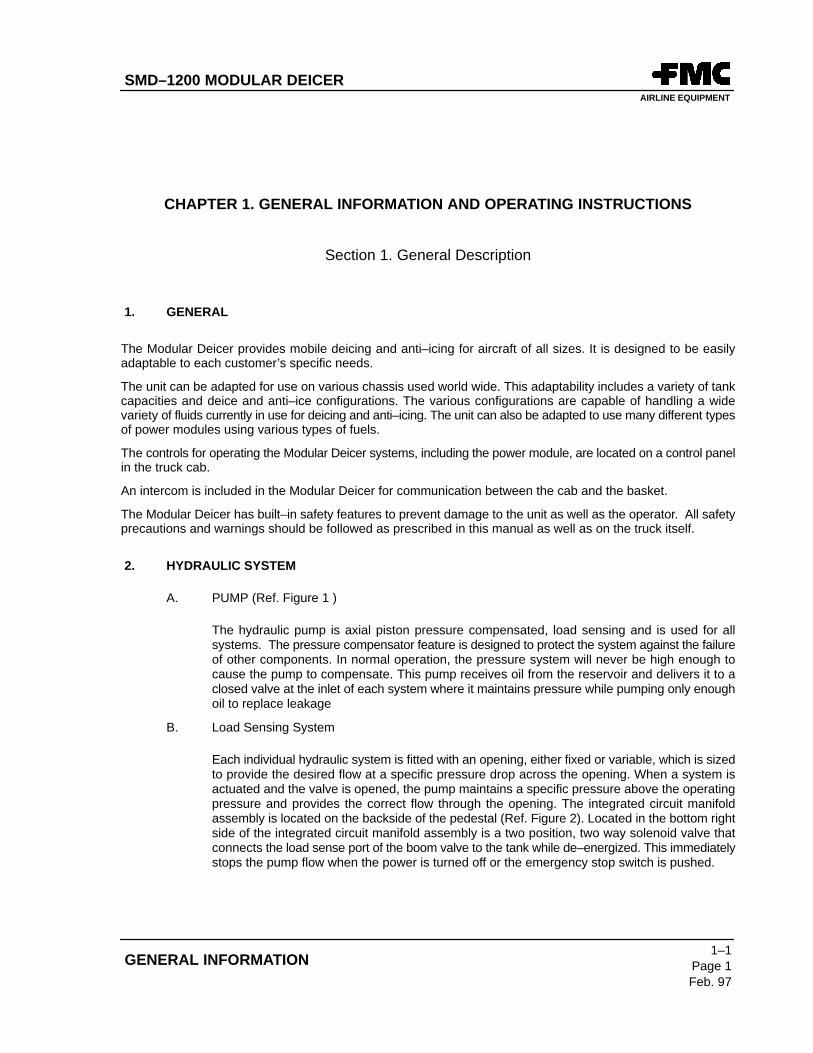
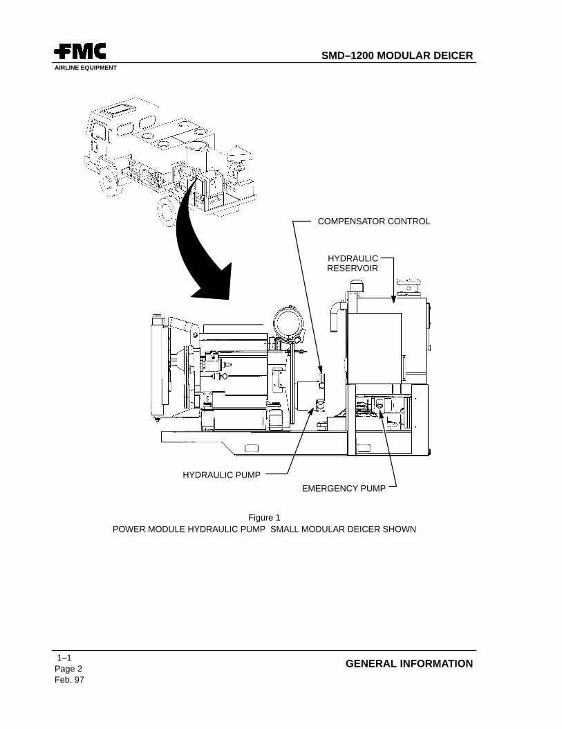
A. PUMP (Ref. Figure 1 )
The hydraulic pump is axial piston pressure compensated, load sensing and is used for allsystems. The pressure compensator feature is designed to protect the system against the failureof other components. In normal operation, the pressure system will never be high enough tocause the pump to compensate. This pump receives oil from the reservoir and delivers it to aclosed valve at the inlet of each system where it maintains pressure while pumping only enoughoil to replace leakage
B. Load Sensing System
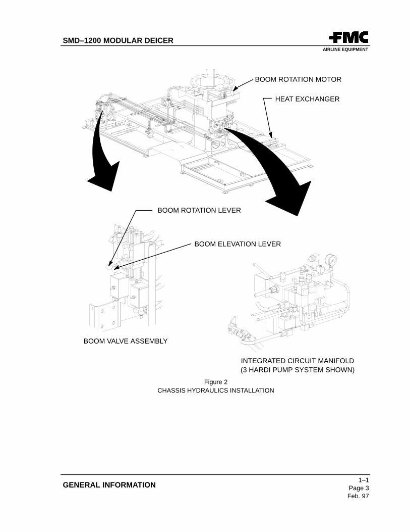
Each individual hydraulic system is fitted with an opening, either fixed or variable, which is sizedto provide the desired flow at a specific pressure drop across the opening. When a system isactuated and the valve is opened, the pump maintains a specific pressure above the operatingpressure and provides the correct flow through the opening. The integrated circuit manifoldassembly is located on the backside of the pedestal (Ref. Figure 2). Located in the bottom rightside of the integrated circuit manifold assembly is a two position, two way solenoid valve thatconnects the load sense port of the boom valve to the tank while de–energized. This immediatelystops the pump flow when the power is turned off or the emergency stop switch is pushed.
SMD–1200 MODULAR DEICERAIRLINE EQUIPMENT
1–1Page 2Feb. 97
GENERAL INFORMATION
COMPENSATOR CONTROL
HYDRAULICRESERVOIR
HYDRAULIC PUMP
EMERGENCY PUMP
Figure 1POWER MODULE HYDRAULIC PUMP SMALL MODULAR DEICER SHOWN
SMD–1200 MODULAR DEICERAIRLINE EQUIPMENT
1–1Page 3Feb. 97
GENERAL INFORMATION
BOOM ROTATION LEVER
BOOM ELEVATION LEVER
BOOM VALVE ASSEMBLY
INTEGRATED CIRCUIT MANIFOLD
HEAT EXCHANGER
BOOM ROTATION MOTOR
(3 HARDI PUMP SYSTEM SHOWN)
Figure 2CHASSIS HYDRAULICS INSTALLATION
SMD–1200 MODULAR DEICERAIRLINE EQUIPMENT
1–1Page 4Feb. 97
GENERAL INFORMATION
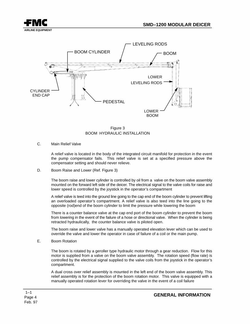
BOOM CYLINDER
LEVELING RODS
BOOM
LOWER
LEVELING RODS
PEDESTAL
CYLINDEREND CAP
LOWERBOOM
Figure 3BOOM HYDRAULIC INSTALLATION
C. Main Relief Valve
A relief valve is located in the body of the integrated circuit manifold for protection in the eventthe pump compensator fails. This relief valve is set at a specified pressure above thecompensator setting and should never relieve.
D. Boom Raise and Lower (Ref. Figure 3)
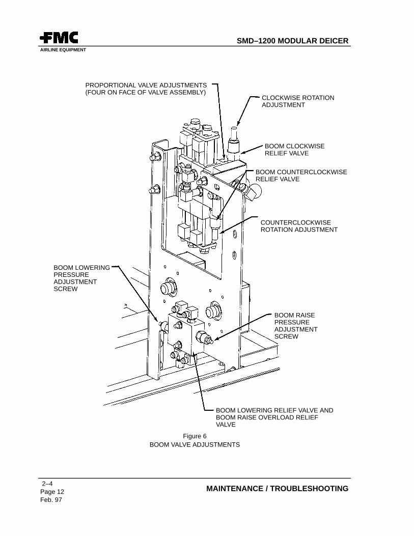
The boom raise and lower cylinder is controlled by oil from a valve on the boom valve assemblymounted on the forward left side of the deicer. The electrical signal to the valve coils for raise andlower speed is controlled by the joystick in the operator’s compartment
A relief valve is teed into the ground line going to the cap end of the boom cylinder to prevent liftingan overloaded operator’s compartment. A relief valve is also teed into the line going to theopposite (rod)end of the boom cylinder to limit the pressure while lowering the boom
There is a counter balance valve at the cap end port of the boom cylinder to prevent the boomfrom lowering in the event of the failure of a hose or directional valve. When the cylinder is beingretracted hydraulically, the counter balance valve is piloted open.
The boom raise and lower valve has a manually operated elevation lever which can be used tooverride the valve and lower the operator in case of failure of a coil or the main pump.
E. Boom Rotation
The boom is rotated by a geroller type hydraulic motor through a gear reduction. Flow for thismotor is supplied from a valve on the boom valve assembly. The rotation speed (flow rate) iscontrolled by the electrical signal supplied to the valve coils from the joystick in the operator’scompartment.
A dual cross over relief assembly is mounted in the left end of the boom valve assembly. Thisrelief assembly is for the protection of the boom rotation motor. This valve is equipped with amanually operated rotation lever for overriding the valve in the event of a coil failure
SMD–1200 MODULAR DEICERAIRLINE EQUIPMENT
1–1Page 5Feb. 97
GENERAL INFORMATION
F. Deicing Delivery Pump
The diaphragm pump that delivers deicing fluid is driven by a fixed displacement motor. Hydraulicfluid for this motor is supplied by a solenoid valve located at the left side of the integrated circuitmanifold assembly (Ref Figure 2). The flow rate to this motor is controlled by a flow control valvecartridge screwed into a sandwich valve directly under the solenoid valve. This flow control valveis adjustable by means of an allen head screw.
G. Anti–ice / Refiller
The diaphragm pump that delivers the optional anti–Ice fluid is driven by a fixed displacementmotor. Hydraulic fluid for this motor is supplied from a solenoid valve on the left end of theintegrated circuit manifold. The flow rate to this motor is controlled by a flow control valvecartridge screwed into a sandwich valve located on top of the manifold. This flow control valveis adjustable by means of an allen head screw. Pressure to the drive motor is regulated by apressure reducing valve cartridge located directly under the solenoid valve. This valve cartridgeprovides constant pressure Anti–Ice fluid to the nozzle independent of the flow rate. When thenozzle is closed, the hydraulic system maintains a constant static pressure at the nozzle
H. Blower Drive
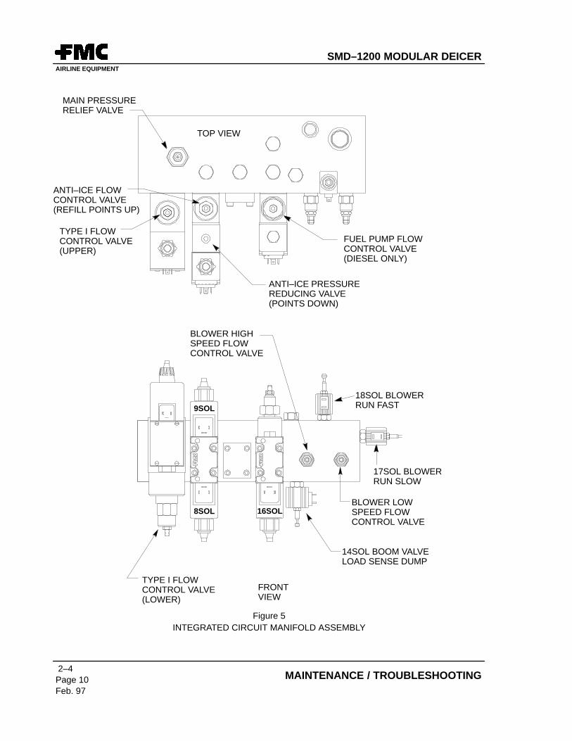
The blower fan for the fluid heater is driven by a fixed displacement motor. Hydraulic fluid for lowspeed start up operation of the blower fan is supplied from a solenoid valve cartridge at theright–hand side of the integrated circuit manifold, near the pressure gauge. The speed of themotor is controlled by the flow control valve cartridge located at the lower right–hand corner ofthe front face of this same manifold. Hydraulic fluid for high speed operation of the blower fan issupplied from a solenoid valve cartridge at the top right–hand side of the integrated circuitmanifold. High speed operation of the motor is controlled by the flow control valve cartridgelocated at the left side of the low speed flow control valve cartridge.
I. Fluid Heater Fuel Pump Drive (optional)
The fuel pump for the diesel fired fluid heater is driven at a constant speed by a hydraulic motor.Hydraulic oil to drive the motor is supplied by a solenoid valve through a pressure compensatedflow control valve. These valves are located at the right side end of the integrated circuit manifold.Constant fuel pressure is maintained by a relief valve between the fuel pump and the burnernozzle.
J. Emergency Pump (Ref. Figure 1)
The Modular Deicer has an optional electrically powered hydraulic pump for use in anemergency, such as the failure of the engine or main pump while the operator is elevated in theoperator’s compartment. This pump can be used to rotate and lower the boom. A check valveprevents the emergency pump flow from flowing through the main pump in the event of a failure.
K. Heat Exchanger
Two oil to air heat exchangers are installed in the return to tank line of the hydraulic system toprevent the hydraulic oil from over heating. One heat exchanger is located under the hydraulicreservoir and the other is located under the heater module. The exchangers have electric motordriven fans to move air through the fins of the oil coolers. A temperature switch located insidethe hydraulic reservoir controls the fan motors.
SMD–1200 MODULAR DEICERAIRLINE EQUIPMENT
1–1Page 6Feb. 97
GENERAL INFORMATION
L. Filtration
Fluid returning to the hydraulic reservoir passes through a 10 micron filter with a built–in bypassrelief valve. Air entering the hydraulic reservoir is filtered through a breather mounted on top ofthe reservoir. Fluid from the case drain port of the main hydraulic pump passes through a 10micron filter with a built–in bypass relief valve. Fluid from the case drain port of the main hydraulicpump passes through a 10 micron filter with a built–in bypass relief valve.
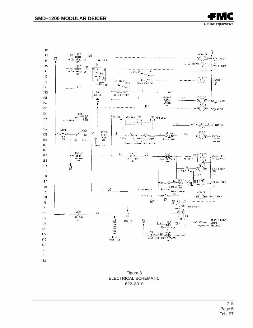
3. ELECTRICAL SYSTEM
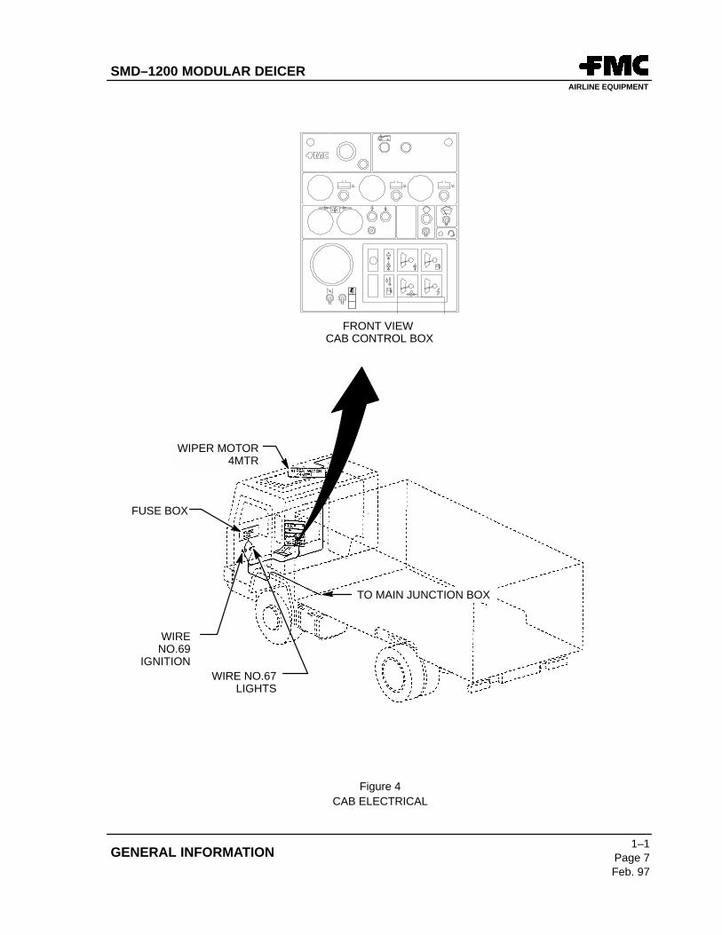
A. Cab Electrical (Ref. Figure 4)
The cab electrical consists of a cab control box in which most of the Modular Deicercontrols/indicators are located. The top window wiper motor harness and chassis powerharnesses branch off from the cab control box harness. The control box is mounted on apedestal, and is connected by a rectangular connector coming from the main junction box in theleft rear of the Modular Deicer.
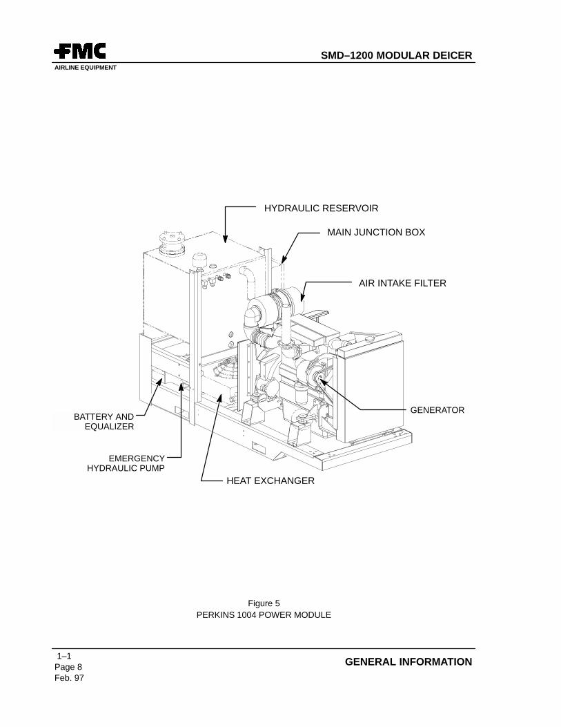
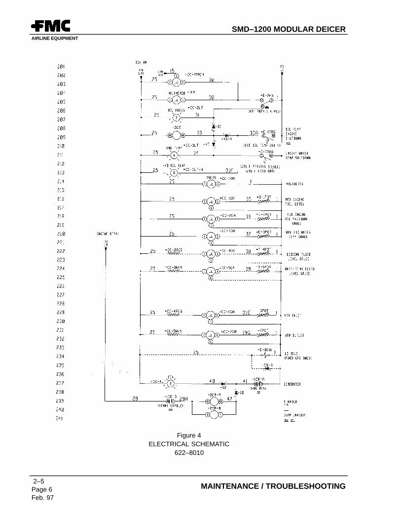
B. Power Module (Ref. Figure 5)
The power module contains the main junction box that ties all other areas together. A batteryequalizer, two 12 volt batteries and an oil cooler fan are also located on the power module. Thebatteries are connected in series for 24 volts and some 12 volt loads are used off the center tap.The battery equalizer maintains an equal charge on each battery.
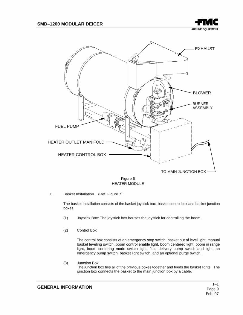
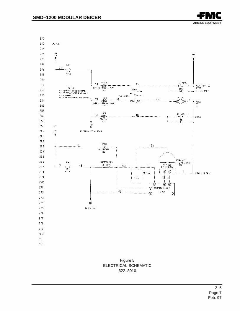
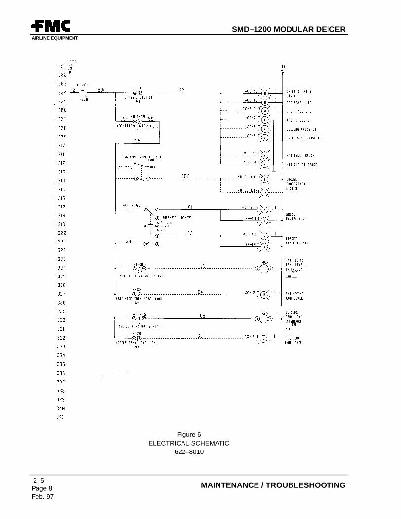
C. Heater Module (Ref Figure 6)
The heater module electrical consists of the controls (timers, relays and maintenance lights) inthe heater control box. A harness from the main junction feeds power to the heater control box.A harness also feeds the heater and associated heater controls in the inlet and outlet plumbing.
SMD–1200 MODULAR DEICERAIRLINE EQUIPMENT
1–1Page 7Feb. 97
GENERAL INFORMATION
FRONT VIEW CAB CONTROL BOX
WIRE NO.67LIGHTS
WIRENO.69
IGNITION
FUSE BOX
TO MAIN JUNCTION BOX
WIPER MOTOR4MTR
Figure 4CAB ELECTRICAL
SMD–1200 MODULAR DEICERAIRLINE EQUIPMENT
1–1Page 8Feb. 97
GENERAL INFORMATION
HYDRAULIC RESERVOIR
BATTERY ANDEQUALIZER
EMERGENCYHYDRAULIC PUMP
MAIN JUNCTION BOX
AIR INTAKE FILTER
GENERATOR
HEAT EXCHANGER
Figure 5PERKINS 1004 POWER MODULE
SMD–1200 MODULAR DEICERAIRLINE EQUIPMENT
1–1Page 9Feb. 97
GENERAL INFORMATION
HEATER CONTROL BOX
BLOWER
BURNERASSEMBLY
FUEL PUMP
EXHAUST
TO MAIN JUNCTION BOX
HEATER OUTLET MANIFOLD
Figure 6HEATER MODULE
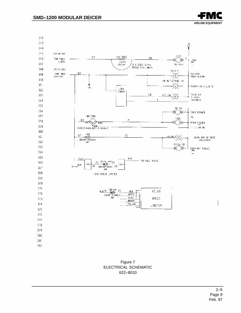
D. Basket Installation (Ref. Figure 7)
The basket installation consists of the basket joystick box, basket control box and basket junctionboxes.
(1) Joystick Box: The joystick box houses the joystick for controlling the boom.
(2) Control Box
The control box consists of an emergency stop switch, basket out of level light, manualbasket leveling switch, boom control enable light, boom centered light, boom in rangelight, boom centering mode switch light, fluid delivery pump switch and light, anemergency pump switch, basket light switch, and an optional purge switch.
(3) Junction BoxThe junction box ties all of the previous boxes together and feeds the basket lights. Thejunction box connects the basket to the main junction box by a cable.
SMD–1200 MODULAR DEICERAIRLINE EQUIPMENT
1–1Page 10Feb. 97
GENERAL INFORMATION
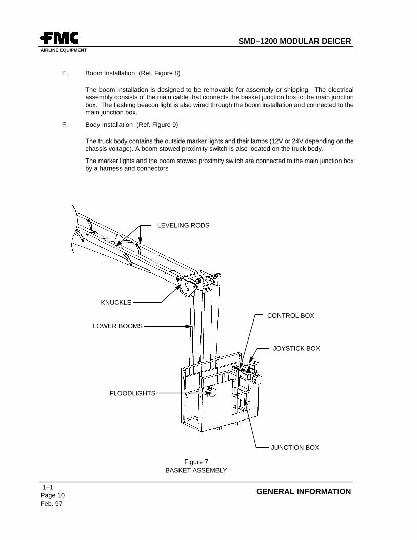
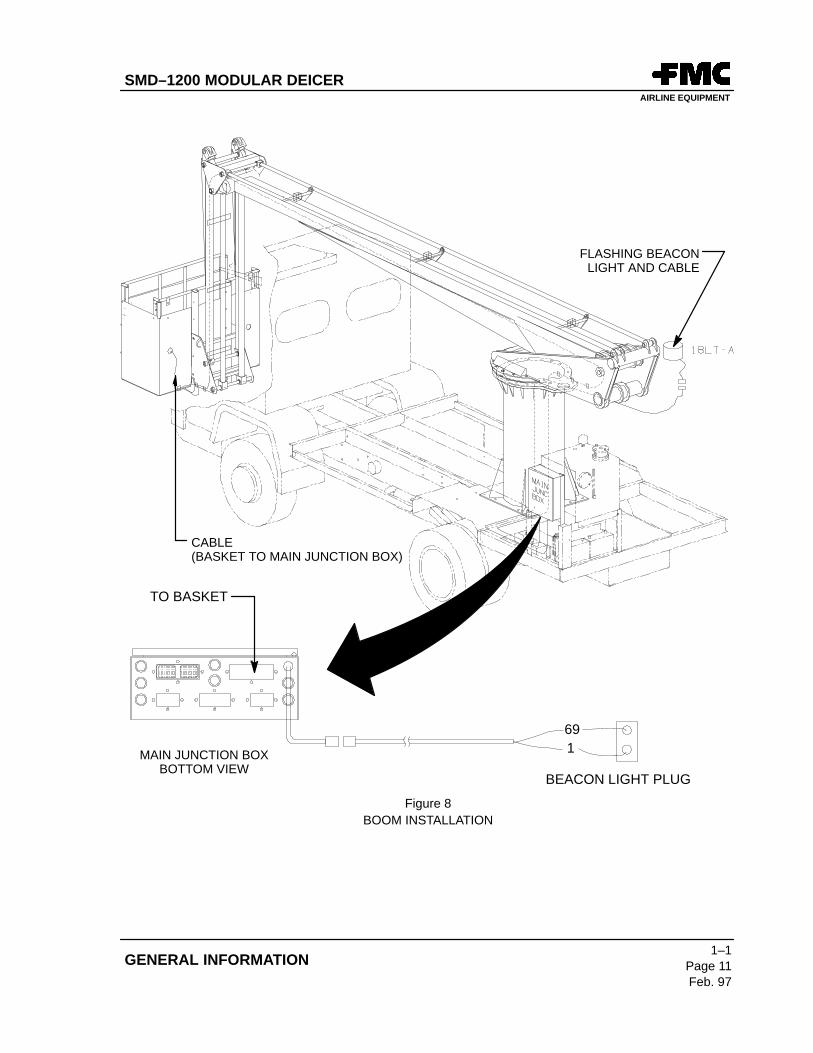
E. Boom Installation (Ref. Figure 8)
The boom installation is designed to be removable for assembly or shipping. The electricalassembly consists of the main cable that connects the basket junction box to the main junctionbox. The flashing beacon light is also wired through the boom installation and connected to themain junction box.
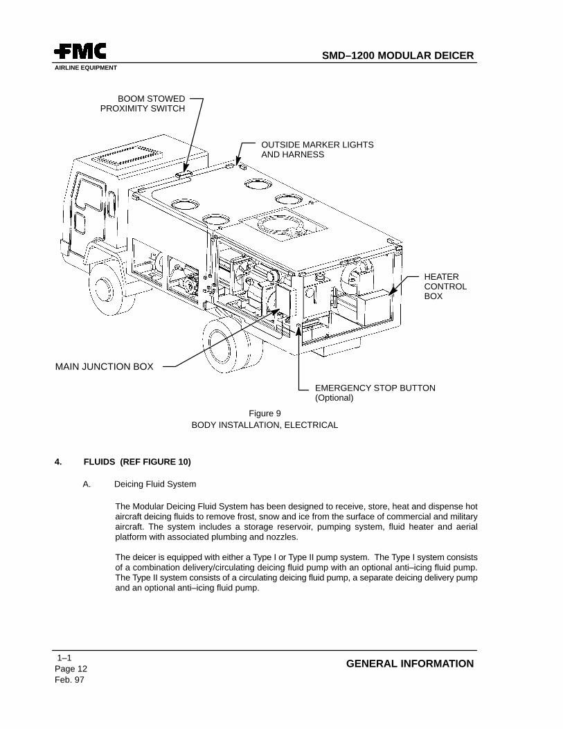
F. Body Installation (Ref. Figure 9)
The truck body contains the outside marker lights and their lamps (12V or 24V depending on thechassis voltage). A boom stowed proximity switch is also located on the truck body.
The marker lights and the boom stowed proximity switch are connected to the main junction boxby a harness and connectors
JUNCTION BOX
JOYSTICK BOX
CONTROL BOX
FLOODLIGHTS
KNUCKLE
LOWER BOOMS
LEVELING RODS
Figure 7BASKET ASSEMBLY
SMD–1200 MODULAR DEICERAIRLINE EQUIPMENT
1–1Page 11Feb. 97
GENERAL INFORMATION
TO BASKET
MAIN JUNCTION BOXBOTTOM VIEW
691
FLASHING BEACONLIGHT AND CABLE
BEACON LIGHT PLUG
CABLE (BASKET TO MAIN JUNCTION BOX)
Figure 8BOOM INSTALLATION
SMD–1200 MODULAR DEICERAIRLINE EQUIPMENT
1–1Page 12Feb. 97
GENERAL INFORMATION
EMERGENCY STOP BUTTON(Optional)
HEATERCONTROLBOX
OUTSIDE MARKER LIGHTSAND HARNESS
BOOM STOWEDPROXIMITY SWITCH
MAIN JUNCTION BOX
Figure 9BODY INSTALLATION, ELECTRICAL
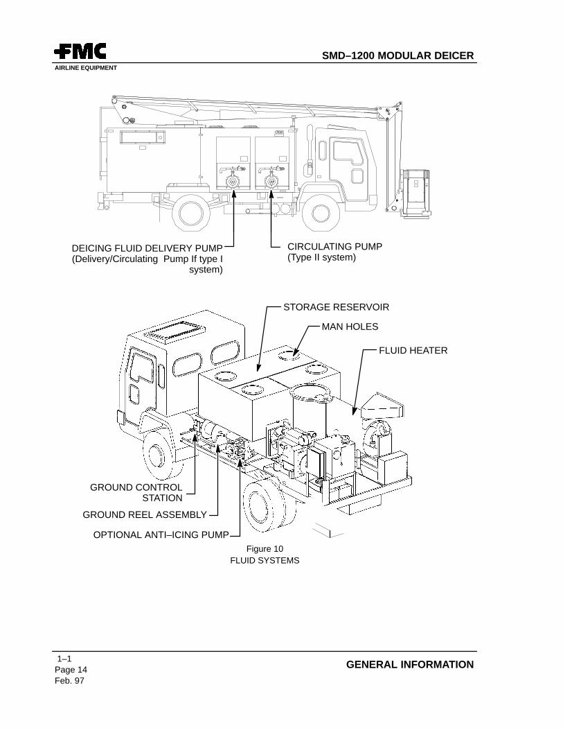
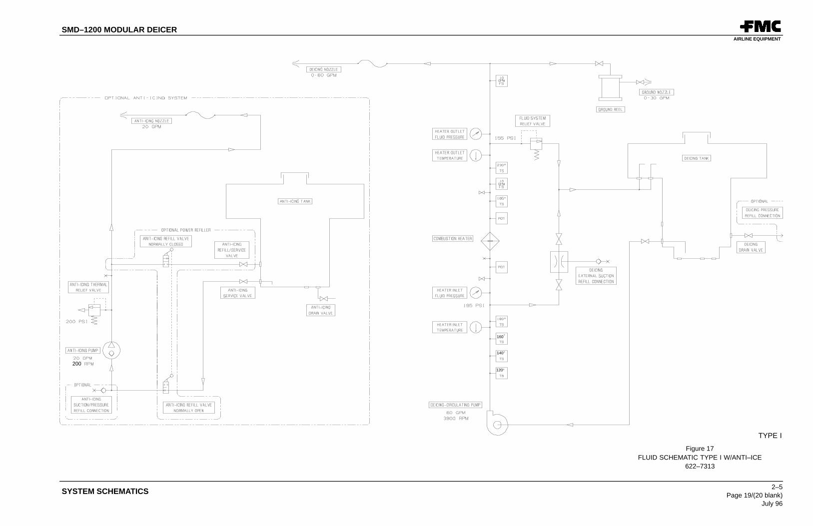
4. FLUIDS (REF FIGURE 10)
A. Deicing Fluid System
The Modular Deicing Fluid System has been designed to receive, store, heat and dispense hotaircraft deicing fluids to remove frost, snow and ice from the surface of commercial and militaryaircraft. The system includes a storage reservoir, pumping system, fluid heater and aerialplatform with associated plumbing and nozzles.
The deicer is equipped with either a Type I or Type II pump system. The Type I system consistsof a combination delivery/circulating deicing fluid pump with an optional anti–icing fluid pump.The Type II system consists of a circulating deicing fluid pump, a separate deicing delivery pumpand an optional anti–icing fluid pump.
SMD–1200 MODULAR DEICERAIRLINE EQUIPMENT
1–1Page 13Feb. 97
GENERAL INFORMATION
(1) Storage Reservoir
The storage reservoir comes in a variety of sizes for deicing fluid only or a combinationof deicing and optional anti–icing fluid. The reservoir is constructed of stainless steel toreduce maintenance and increase the life of the tank as well as protect sensitiveanti–icing fluids. Exterior man holes have been supplied for cleaning and maintenance.
(2) Pumping System
The deicing delivery pump is a two stage centrifugal or diaphragm pump used to circulatedeicing fluid through the heater. A second diaphragm pump then delivers the deicingfluid to the basket and ground reel hose. Plumbing from the reservoir to these pumpsincludes service valves, stainless plumbing, and high temperature hose.
(3) Fluid Heater
The heater is self controlled and regulating during operation and will automatically turnoff when the reservoir has reached deicing temperatures. The internal heating flame isfully enclosed allowing heating operations around aircraft. The heater will raise the fluidtemperature very quickly. The fluid is returned to the reservoir during heater operation,rapidly heating the stored deicing fluid.
(4) Aerial Platform
Boom movement is controlled by the basket joystick, optional cab controls, or the controllevers located at the ground control station (Ref. Figure 10). The optional cab boomcontrols will override the basket joystick and the ground control levers will override thebasket joystick and cab boom controls. Aircraft deicing can be accomplished using thebasket nozzle or the ground level hose reel nozzle.
B. Anti–icing Fluid System (Optional)
An anti–icing system may be installed for coating the aircraft skin immediately after deicingoperations to increase hold–over times.
(1) Storage Reservoir
When this system is installed, the main reservoir is partitioned off to contain theanti–icing fluid.
(2) Pumping System
An additional high volume anti–icing pump, associated plumbing, and special nozzle isused to dispense the anti–icing fluid. This fluid is not heated and can only be dispensedfrom the basket. The anti–icing pump transfers anti–icing fluid from the reservoir,increases the pressure to working levels, and transfers the fluid to the basket.
NOTE: There is no On–Off switch for the anti–icing pump. The anti–icing pump is activewhenever the auxiliary engine is running and sufficient fluid is available.
SMD–1200 MODULAR DEICERAIRLINE EQUIPMENT
1–1Page 14Feb. 97
GENERAL INFORMATION
GROUND CONTROLSTATION
GROUND REEL ASSEMBLY
OPTIONAL ANTI–ICING PUMP
MAN HOLES
STORAGE RESERVOIR
FLUID HEATER
DEICING FLUID DELIVERY PUMP(Delivery/Circulating Pump If type I
system)
CIRCULATING PUMP(Type II system)
Figure 10FLUID SYSTEMS
SMD–1200 MODULAR DEICERAIRLINE EQUIPMENT
1–1Page 15Feb. 97
GENERAL INFORMATION
HYDRAULIC RESERVOIR
MAIN JUNCTION BOX
AIR INTAKE FILTER
HEAT EXCHANGER
BATTERIES ANDEQUALIZER
EMERGENCYHYDRAULIC PUMP
GENERATOR
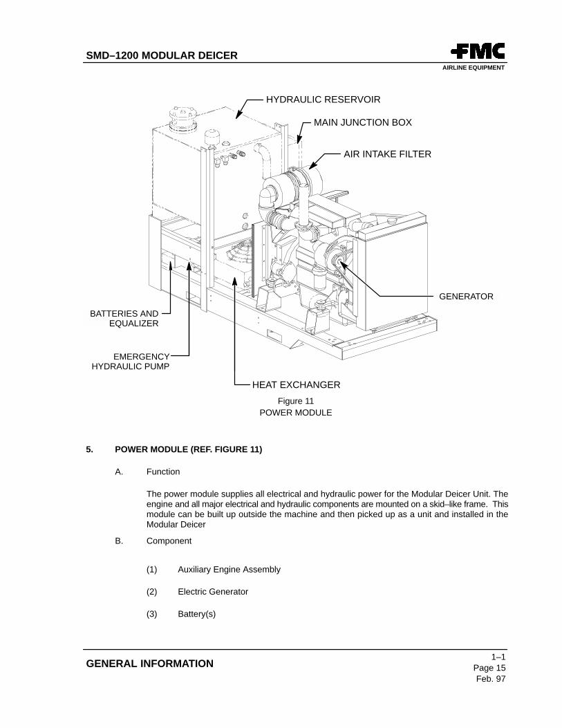
Figure 11POWER MODULE
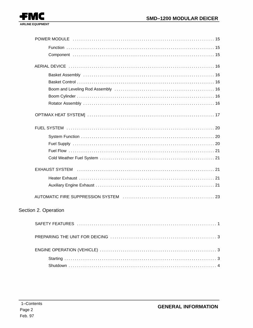
5. POWER MODULE (REF. FIGURE 11)
A. Function
The power module supplies all electrical and hydraulic power for the Modular Deicer Unit. Theengine and all major electrical and hydraulic components are mounted on a skid–like frame. Thismodule can be built up outside the machine and then picked up as a unit and installed in theModular Deicer
B. Component
(1) Auxiliary Engine Assembly
(2) Electric Generator
(3) Battery(s)
SMD–1200 MODULAR DEICERAIRLINE EQUIPMENT
1–1Page 16Feb. 97
GENERAL INFORMATION
(4) Battery Equalizer
(5) Main Electrical Junction Box
(6) Hydraulic Pump (mounted directly on rear of engine)
(7) Hydraulic Reservoir with Return Flow Filter
(8) Heat Exchanger (Hydraulic Oil Cooler and Fan)
(9) Emergency Electric Driven Hydraulic Pump
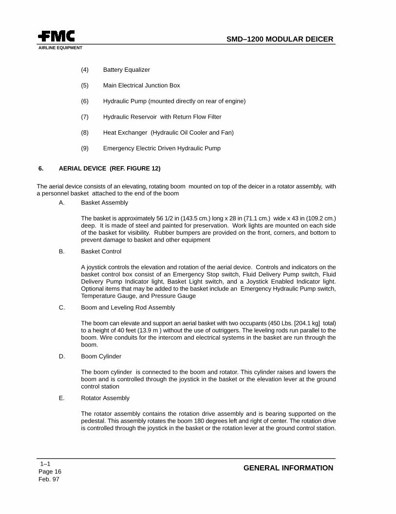
6. AERIAL DEVICE (REF. FIGURE 12)
The aerial device consists of an elevating, rotating boom mounted on top of the deicer in a rotator assembly, witha personnel basket attached to the end of the boom
A. Basket Assembly
The basket is approximately 56 1/2 in (143.5 cm.) long x 28 in (71.1 cm.) wide x 43 in (109.2 cm.)deep. It is made of steel and painted for preservation. Work lights are mounted on each sideof the basket for visibility. Rubber bumpers are provided on the front, corners, and bottom toprevent damage to basket and other equipment
B. Basket Control
A joystick controls the elevation and rotation of the aerial device. Controls and indicators on thebasket control box consist of an Emergency Stop switch, Fluid Delivery Pump switch, FluidDelivery Pump Indicator light, Basket Light switch, and a Joystick Enabled Indicator light.Optional items that may be added to the basket include an Emergency Hydraulic Pump switch,Temperature Gauge, and Pressure Gauge
C. Boom and Leveling Rod Assembly
The boom can elevate and support an aerial basket with two occupants (450 Lbs. [204.1 kg] total)to a height of 40 feet (13.9 m ) without the use of outriggers. The leveling rods run parallel to theboom. Wire conduits for the intercom and electrical systems in the basket are run through theboom.
D. Boom Cylinder
The boom cylinder is connected to the boom and rotator. This cylinder raises and lowers theboom and is controlled through the joystick in the basket or the elevation lever at the groundcontrol station
E. Rotator Assembly
The rotator assembly contains the rotation drive assembly and is bearing supported on thepedestal. This assembly rotates the boom 180 degrees left and right of center. The rotation driveis controlled through the joystick in the basket or the rotation lever at the ground control station.
SMD–1200 MODULAR DEICERAIRLINE EQUIPMENT
1–1Page 17Feb. 97
GENERAL INFORMATION
BOOM CYLINDER
LEVELING RODS
BASKET CONTROL PANEL
BOOM
LOWER LEVELINGRODS
LOWER BOOMPEDESTALROTATOR
ASSEMBLY
Figure 12AERIAL DEVICE
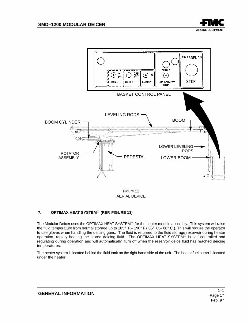
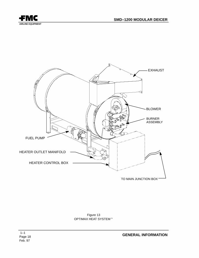
7. OPTIMAX HEAT SYSTEM (REF. FIGURE 13)
The Modular Deicer uses the OPTIMAX HEAT SYSTEM� for the heater module assembly. This system will raisethe fluid temperature from normal storage up to 185° F.– 190° F ( 85° C.– 88° C.). This will require the operatorto use gloves when handling the deicing guns. The fluid is returned to the fluid storage reservoir during heateroperation, rapidly heating the stored deicing fluid. The OPTIMAX HEAT SYSTEM is self controlled andregulating during operation and will automatically turn off when the reservoir deice fluid has reached deicingtemperatures.
The heater system is located behind the fluid tank on the right hand side of the unit. The heater fuel pump is locatedunder the heater
SMD–1200 MODULAR DEICERAIRLINE EQUIPMENT
1–1Page 18Feb. 97
GENERAL INFORMATION
HEATER CONTROL BOX
BLOWER
BURNERASSEMBLY
FUEL PUMP
EXHAUST
TO MAIN JUNCTION BOX
HEATER OUTLET MANIFOLD
Figure 13OPTIMAX HEAT SYSTEM�
SMD–1200 MODULAR DEICERAIRLINE EQUIPMENT
1–1Page 19Feb. 97
GENERAL INFORMATION
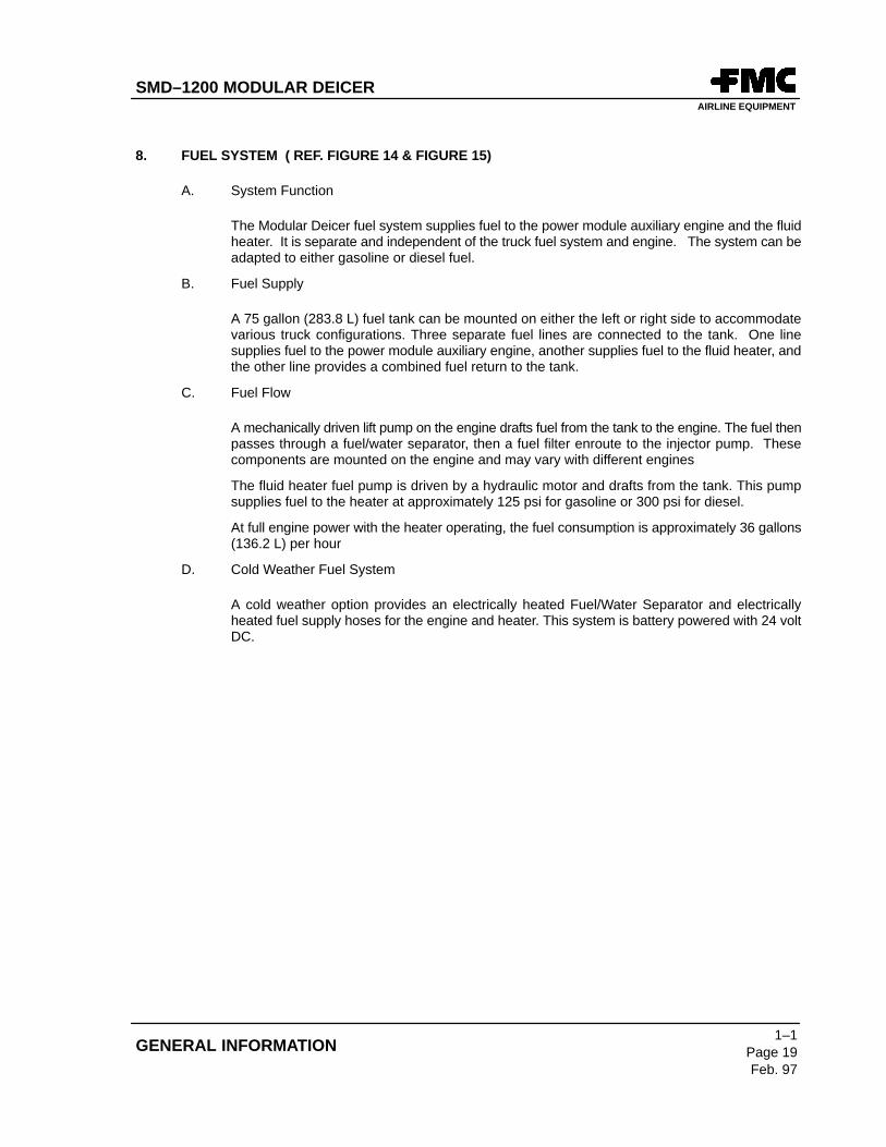
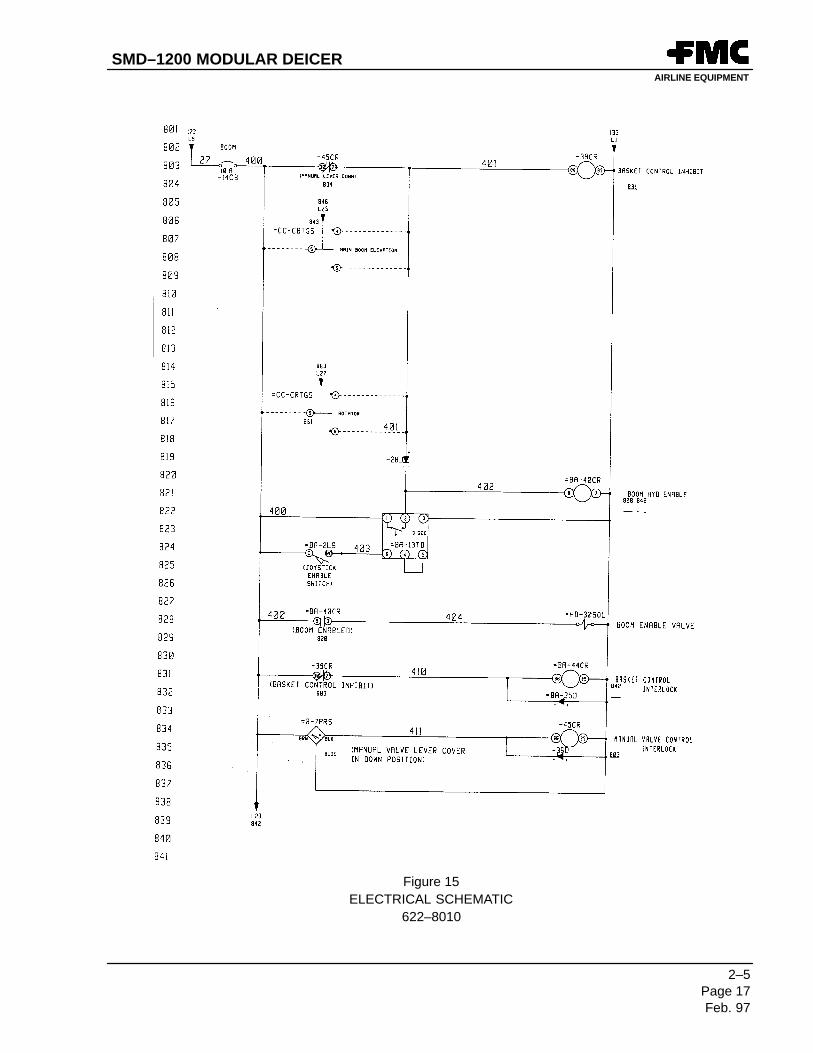
8. FUEL SYSTEM ( REF. FIGURE 14 & FIGURE 15)
A. System Function
The Modular Deicer fuel system supplies fuel to the power module auxiliary engine and the fluidheater. It is separate and independent of the truck fuel system and engine. The system can beadapted to either gasoline or diesel fuel.
B. Fuel Supply
A 75 gallon (283.8 L) fuel tank can be mounted on either the left or right side to accommodatevarious truck configurations. Three separate fuel lines are connected to the tank. One linesupplies fuel to the power module auxiliary engine, another supplies fuel to the fluid heater, andthe other line provides a combined fuel return to the tank.
C. Fuel Flow
A mechanically driven lift pump on the engine drafts fuel from the tank to the engine. The fuel thenpasses through a fuel/water separator, then a fuel filter enroute to the injector pump. Thesecomponents are mounted on the engine and may vary with different engines
The fluid heater fuel pump is driven by a hydraulic motor and drafts from the tank. This pumpsupplies fuel to the heater at approximately 125 psi for gasoline or 300 psi for diesel.
At full engine power with the heater operating, the fuel consumption is approximately 36 gallons(136.2 L) per hour
D. Cold Weather Fuel System
A cold weather option provides an electrically heated Fuel/Water Separator and electricallyheated fuel supply hoses for the engine and heater. This system is battery powered with 24 voltDC.
SMD–1200 MODULAR DEICERAIRLINE EQUIPMENT
1–1Page 20Feb. 97
GENERAL INFORMATION
FUEL WATER SEPARATOR
FUEL FILTER
HEATER FUEL PUMP
Figure 14FUEL SYSTEM
SMD–1200 MODULAR DEICERAIRLINE EQUIPMENT
1–1Page 21Feb. 97
GENERAL INFORMATION
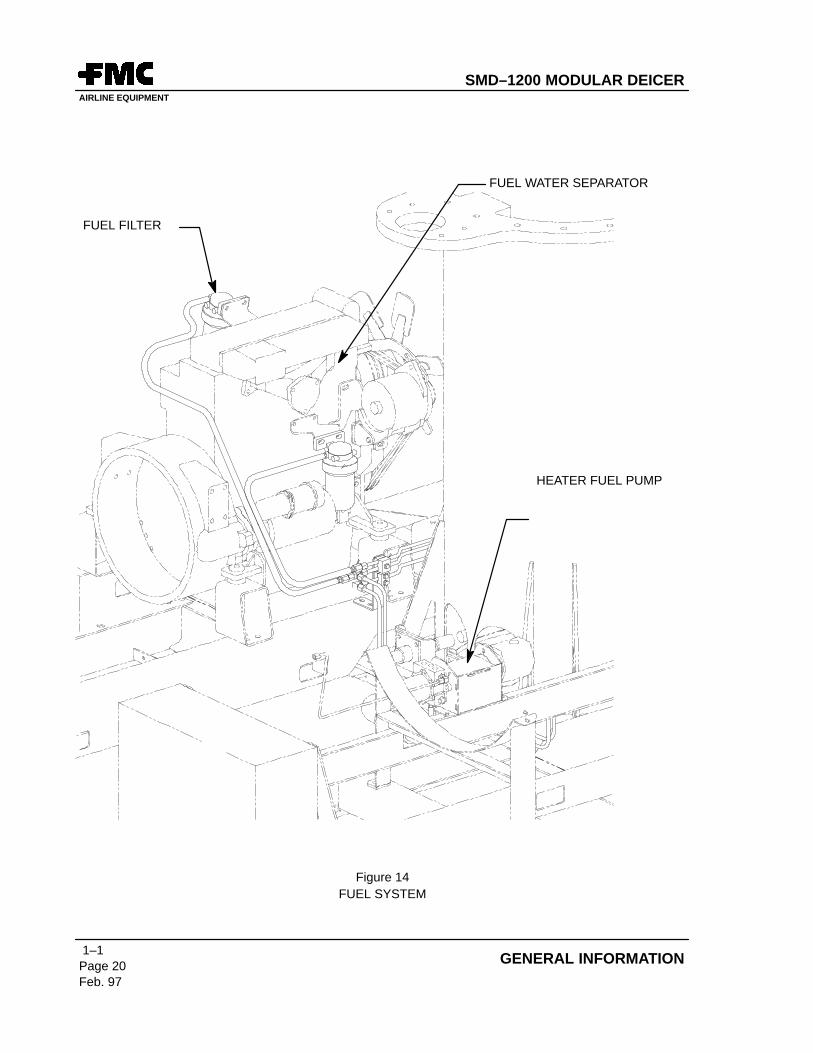
HEATER FUEL SUPPLY
HEATER FUELRETURN
TOP TUBE – AUXILIARY ENGINE SUPPLYMIDDLE TUBE – RETURN (HEATER AND AUX. ENG.)BOTTOM TUBE – HEATER SUPPLY
Figure 15FUEL SYSTEM
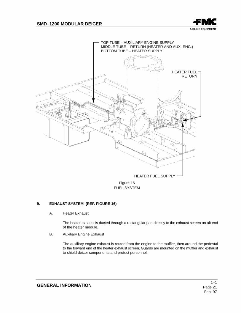
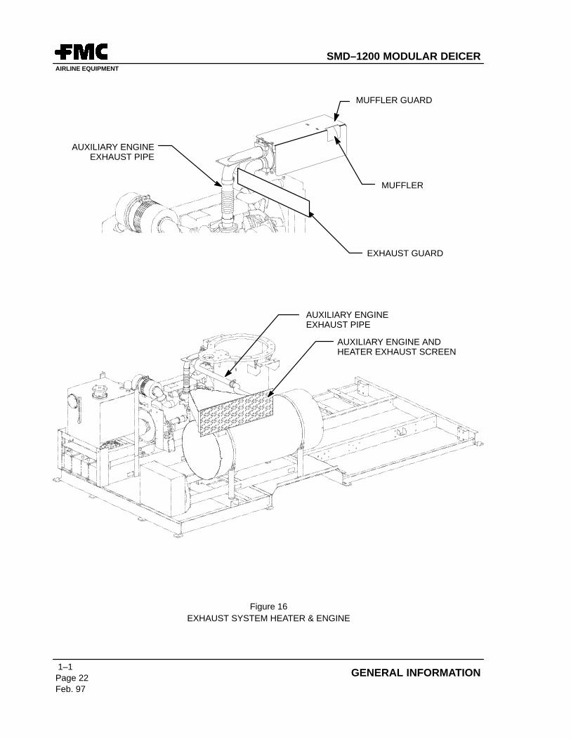
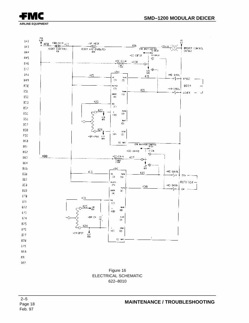
9. EXHAUST SYSTEM (REF. FIGURE 16)
A. Heater Exhaust
The heater exhaust is ducted through a rectangular port directly to the exhaust screen on aft endof the heater module.
B. Auxiliary Engine Exhaust
The auxiliary engine exhaust is routed from the engine to the muffler, then around the pedestalto the forward end of the heater exhaust screen. Guards are mounted on the muffler and exhaustto shield deicer components and protect personnel.
SMD–1200 MODULAR DEICERAIRLINE EQUIPMENT
1–1Page 22Feb. 97
GENERAL INFORMATION
MUFFLER
MUFFLER GUARD
EXHAUST GUARD
AUXILIARY ENGINEEXHAUST PIPE
ÂÂÂÂÂÂÂÂÂÂÂÂÂÂÂÂÂÂÂÂÂÂÂÂÂÂÂÂ
AUXILIARY ENGINE ANDHEATER EXHAUST SCREEN
AUXILIARY ENGINEEXHAUST PIPE
Figure 16EXHAUST SYSTEM HEATER & ENGINE
SMD–1200 MODULAR DEICERAIRLINE EQUIPMENT
1–1Page 23/(24 blank)
Feb. 97
GENERAL INFORMATION
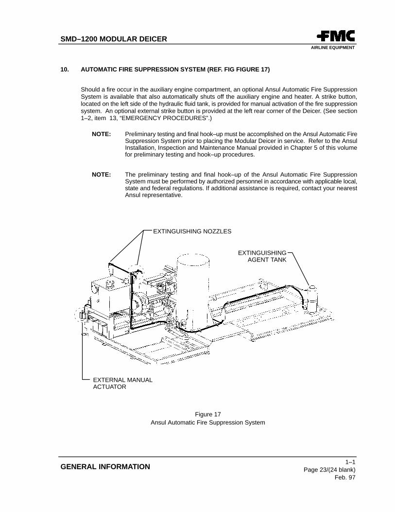
10. AUTOMATIC FIRE SUPPRESSION SYSTEM (REF. FIG FIGURE 17)
Should a fire occur in the auxiliary engine compartment, an optional Ansul Automatic Fire SuppressionSystem is available that also automatically shuts off the auxiliary engine and heater. A strike button,located on the left side of the hydraulic fluid tank, is provided for manual activation of the fire suppressionsystem. An optional external strike button is provided at the left rear corner of the Deicer. (See section1–2, item 13, “EMERGENCY PROCEDURES”.)
NOTE: Preliminary testing and final hook–up must be accomplished on the Ansul Automatic FireSuppression System prior to placing the Modular Deicer in service. Refer to the AnsulInstallation, Inspection and Maintenance Manual provided in Chapter 5 of this volumefor preliminary testing and hook–up procedures.
NOTE: The preliminary testing and final hook–up of the Ansul Automatic Fire SuppressionSystem must be performed by authorized personnel in accordance with applicable local,state and federal regulations. If additional assistance is required, contact your nearestAnsul representative.
EXTINGUISHINGAGENT TANK
EXTERNAL MANUALACTUATOR
EXTINGUISHING NOZZLES
Figure 17Ansul Automatic Fire Suppression System
SMD–1200 MODULAR DEICERAIRLINE EQUIPMENT
1–2Page 1Feb. 97
SECTION 2. OPERATION
Section 2. Operation
ENSURE DEICER BODY ACCESS DOORS ARE FIRMLY SECURED IN THEOPEN POSITION WHEN ACCESSING CONTROLS AND EQUIPMENT.
1. SAFETY FEATURES
A. The Emergency Stop switches will immediately shut down the power module auxiliary engine,heater, fluid pumps, and hydraulics for boom movements. Optional – Some units will also applychassis brakes if the boom is out of rest.
B. The power module auxiliary engine will automatically shut down in the event of low oil pressure,high coolant temperature, or high hydraulic oil temperature.
C. The power module auxiliary engine starter can not be engaged while the engine is running.
D. The heater will shut down if any of the following conditions occur:
(1) Low fluid flow
(2) Auxiliary engine not at high throttle
(3) Low blower speed
(4) Heater outlet temperature exceeds 230º F (110º C)0
(5) Fluid tank exceeds 180º F (82º C)
(6) Exhaust stack sensor switch (7TAS) exceeds 1400º F (760º C)
E. The boom will not lift more than the rated basket load (450 Lbs. [204.1 kg]) from the rest position.
Optional: Some units may be equipped with a warning light in the basket and at the ground controlstation to indicate a boom overload.
SMD–1200 MODULAR DEICERAIRLINE EQUIPMENT
1–2
Page 2
Feb. 97
GENERAL INFORMATION
F. The basket is equipped with safety belts and lanyards.
G. Rubber bumpers are provided on the front corners of the basket.
H. Basket door is spring closed and self latching.
I. Chassis mounted torsion bar provides automatic boom stability.
J. All systems, except for heater ignition and chassis lights,use 24 volt D.C. operating voltage.
K. Boom Enable switch is incorporated on boom joystick control.
L. All cylinders used on the aerial device incorporate a holding valve to prevent rapid lowering ofboom in the event of hydraulic line failure.
Optional: Some units may be equipped with a battery powered hydraulic pump for emergencyboom lowering.
M. Fluid tank is compartmentalized to prevent large fluid movements.
N. Boom Out of Rest light is provided on Cab Control Panel.
O. Manual boom control levers are provided at the ground control station on the forward left sideof the Modular Deicer. They allow ground personnel to operate the boom for servicing or if thebasket operator is disabled.
P. An optional automatic fire extinguishing system is provided which also automatically shuts downthe power module auxiliary engine.
Q. Optional Low Fluid Level warning lights are provided on the cab control panel to help preventrunning the fluid tanks empty.
R. An optional Chassis Speed Limiter limits the Modular Deicer to 3.5 mph (6 km/hr) with the boomout of rest.
S. A Boom Control Lockout provides an interlock that disables the basket controls unless the doorto the manual boom levers is closed.
T. An optional Battery Disconnect Switch provides isolators of both positive and negative from the12 volt chassis batteries. The switch is designed so that a lever must be installed and turned inorder for the machine to operate. Once disabled, the lever may be removed so that no one elsecan turn the system on.
U. Hydraulic boom enable valve.
SMD–1200 MODULAR DEICERAIRLINE EQUIPMENT
1–2Page 3Feb. 97
SECTION 2. OPERATION
2. PREPARING THE UNIT FOR DEICING
A. Always perform daily maintenance checks. Proper maintenance is necessary to ensure the safeand optimum performance of the Modular Deicer.
(1) Pre–Start Checks
(a) Check the oil level and coolant levels on the power module auxiliary engine andvehicle engine.
(b) Check condition of wiring and hoses.
(c) Check battery connections and water level.
(d) Look underneath vehicle and check for leaks. If significant leaks are foundmaintenance must be performed to eliminate problem.
(e) Check tire pressures.
(f) Check fuel gauges located on the cab control station for fuel supply.
B. Fill the tank with proper amounts of deicing fluid using either the “DEICING SUCTION /PRESSURE REFILL CONNECTION” port in the right side compartment or the “DEICINGPRESSURE REFILL” port in the left hand compartment aft of the hose reel. Fill the aft portionof the tank with anti–icing fluid through the “ANTI–ICING SUCTION / PRESSURE REFILLCONNECTION” port on the anti–icing pump in the left side compartment. (See para. 14. 26REFILL PROCEDURES)
C. Walk around vehicle and inspect for missing or damaged equipment.
3. ENGINE OPERATION (VEHICLE)
A. Starting
(1) Enter vehicle, being careful when climbing into cab. Check that automatic transmissionis in neutral and the parking brake is set.
(2) Start engine – warm up before attempting to move unit.
NOTE: Units with engine block heaters do not require warm up time.
DO NOT EXCEED 4 MPH (6.5 KM/HR) WITH PERSON IN BASKET OR WHENTHE BOOM OUT OF REST LIGHT IS ON.
CHECK VEHICLE HEIGHT TO ENSURE CLEARANCE WHEN OPERATINGAROUND AIRCRAFT AND OTHER OBSTRUCTIONS.
CAUTION
SMD–1200 MODULAR DEICERAIRLINE EQUIPMENT
1–2
Page 4
Feb. 97
GENERAL INFORMATION
25 MPH (40 KM/HR) MAXIMUM ON IMPROVED AIRPORT SURFACESWHEN LOADED. LOADED VEHICLES ARE NOT PERMITTED ON PUBLICROADS.
21. BOOM OUT OF LEVEL WARNING LIGHT (RED) (OPTIONAL)
CAUTION
SMD–1200 MODULAR DEICERAIRLINE EQUIPMENT
1–2Page 5Feb. 97
SECTION 2. OPERATION
1
2
3
4
5
6
7
8 9 10 11 12 13 14
15
16
17
18
19
20 21
OUT OF LEVEL
CHECKE–STOPS
WATERANTI–ICEPREMIX
ANTI–ICINGLEVEL
WATERLEVEL
DEICINGLEVEL
HEATER INLETTEMP
HEATER OUTLET
TEMP
TACHOMETER
FUEL
OIL PRESS VOLTS
G
COOLANTTEMP
Figure 1CAB CONTROL BOX
SMD–1200 MODULAR DEICERAIRLINE EQUIPMENT
1–2
Page 6
Feb. 97
GENERAL INFORMATION
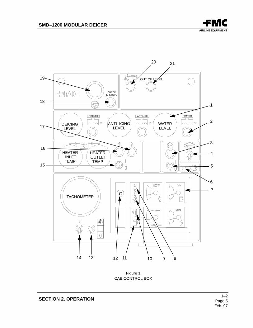
4. POWER MODULE AUXILIARY ENGINE OPERATION (REF. FIGURE 1)
A. Cab Control Box
All controls for starting and stopping the auxiliary engine are located on the cab control box. The cab control boxis mounted on a pedestal to the right of the drivers’ seat.
The cab control box controls/indicators are grouped according to function from bottom to top of the control boxin the order of the start sequence. For example, the auxiliary engine must be started prior to running the heater,therefore, auxiliary engine controls are on the bottom followed by heater controls on top.
B. Auxiliary Engine Controls
Auxiliary Engine controls consist of an “IGNITION SWITCH” and a “START ENABLE SWITCH.”
(1) START ENABLE SWITCH
This switch momentarily bypasses the engine shutdown system to facilitate startingwhile no oil pressure exists. This switch can be held during cold starting to allow theengine to warm up and develop sufficient oil pressure. Some options that are availablemodify this two position switch. “COLD START” is available on diesel engines. Thisoption changes the start enable switch to a three position switch.
(a) Center position is ”OFF.”
(b) Upper position is still the ”START ENABLE” position and is momentary.
(c) New Lower position is also momentary but, when held down, the glow plugheaters on the engine are energizing. This switch is generally held down forabout 30 seconds prior to starting.
For Ford gas engines, this lower position is for priming the carburetor prior tostarting. Selecting this position injects fuel into the carburetor.
Regardless of the version, this “START ENABLE” switch must be held in the “UP”position prior to starting the engine.
(2) IGNITION SWITCH
This switch is always a 3 position switch. The lowest position is ”OFF.”
The center position is the “ON” position. The emergency pump system and the gaugelights can be operated in this position. On a Ford gas engine, the ignition switch shouldremain in this position 3 seconds prior to starting.
The upper position on the ignition switch is the ”START” position and is a momentaryswitch.
NOTE: The ignition switch should always be placed in the ”OFF” position whenever the deiceris not in use to prevent draining the batteries.
SMD–1200 MODULAR DEICERAIRLINE EQUIPMENT
1–2Page 7Feb. 97
SECTION 2. OPERATION
(3) Auxiliary Engine Gauges
(a) Tachometer
The tachometer is located directly above the ignition and start enable switches.Engine speed is automatically controlled, with idle speed set for 1000 RPM andnormal operation set for a ”HI” throttle position of 2000RPM.
(b) Engine Condition Instruments
These instruments are located to the right of the tachometer and consist of 4gauges:
1) Coolant Temperature
2) Fuel Level
3) Oil Pressure
4) Voltmeter
(c) Warning Lights
There are 5 red warning lights on the cab control box associated with theauxiliary engine:
1) High Engine Temperature
2) Low Oil Pressure
3) High Hydraulic Oil Temperature
4) Low Fuel
5) Generator (No Out Put)
C. Auxiliary Engine Start Sequence
(1) Place ignition switch to the “ON” position.
(2) For cold weather start – Hold down ”START ENABLE” switch approximately30 secondsto preheat (diesel engine) or momentarily two or three times to prime (gas engine).
(3) Hold ”START ENABLE” switch ”UP”.
(4) While holding ”START ENABLE” switch ”UP”, push ignition switch to ”START”.
SMD–1200 MODULAR DEICERAIRLINE EQUIPMENT
1–2
Page 8
Feb. 97
GENERAL INFORMATION
(5) The engine is running when the low oil pressure light goes out and the tachometerindicates a steady RPM.
(6) Once the engine is running, release the ignition switch to its ”ON” position.
(7) The ”START ENABLE” switch can remain held in the ”UP” position until indicators showengine is up to speed (engine will idle at 1000 RPM).
The best indicators for a running auxiliary engine are:
1 – Tachometer – Steady RPM (1000 RPM for idle)2 – Generator Light – Out (Not Illuminated)3 – Low Oil Pressure Light – Out (Not Illuminated)
The oil pressure and voltmeter gauges can also be indicators that the engine isrunning. The oil pressure gauge should indicate in the green band and thevoltmeter should indicate in the green band at approximately 24 volts.
NOTE: Once engine is running, the starter will be electrically locked out from re–engaging.
NOTE: The tachometer will have a floating indicator when the ignition is turned off. Once theignition switch is pushed to ”ON”, the needle will go to zero.
D. Auxiliary Engine Shutdown
(1) Turn the heater and deicing fluid delivery pump off if they are operating. The engine willcontinue to run at 2000 RPM until purge cycle is completed (approximately threeminutes).
(2) Allow the engine to idle (1000 RPM) for approximately two minutes to properly cooldown.
(3) Turn the ignition switch off.
NOTE: The ignition switch should always be placed in the ”OFF” position whenever the deiceris not in use to prevent draining the batteries.
5. HEATER OPERATION
A. Control Functions
(1) The heater control consists of a 3 position, center off, momentary switch for starting andstopping the heater.
SMD–1200 MODULAR DEICERAIRLINE EQUIPMENT
1–2Page 9Feb. 97
SECTION 2. OPERATION
(2) Two indicator lights accompany the switch.
(a) The GREEN LIGHT directly above the switch indicates that the heater has beenenabled and the firing sequence has begun.
(b) The WHITE LIGHT above and to the right of the switch indicates that flame hasbeen established and the heater is operating.
(3) The two gauges to the left of the switch indicate fluid temperature at the heater inlet andheater outlet.
B. Heater Start Sequence
(1) After engine is running push HEATER SWITCH to “ON”.
The GREEN LIGHT should immediately illuminate. The switch can now be released andthe light should remain illuminated. This indicates that the firing sequence is under way.
(2) Engine RPM automatically increases to 2000 RPM. After approximately 30 seconds theWHITE LIGHT will illuminate and remain on, indicating that the flame has beenestablished and the heater is operating.
(3) Monitor the temperature gauges to determine fluid temperature.
NOTE: If the GREEN LIGHT does not illuminate, check tank temperature. If temperature isabove 180ºF (82ºC) the heater circuitry is disabled.
NOTE: If WHITE LIGHT does not illuminate, call for service.
C. Heater Cycle
(1) The heater will shut down automatically when the fluid temperature reaches 180º F (82ºC) (normally 20 to 30 minutes) and both the WHITE LIGHT and GREEN LIGHT willextinguish.
(2) After shut down, the heater fluid pump and air blower will continue to run for threeminutes to reduce the heater temperature and purge any fumes and unburned fuel thatmay remain after shut down. After this purge cycle is complete the engine will return toidle speed.
(3) Monitor the temperature gauges on the cab control panel or, if equipped,on the basketcontrol panel to determine fluid temperature. The heater will not restart automatically ifthe fluid temperature falls below acceptable levels. It will be necessary for the operatorto restart the heater if the fluid temperature is too low.
SMD–1200 MODULAR DEICERAIRLINE EQUIPMENT
1–2
Page 10
Feb. 97
GENERAL INFORMATION
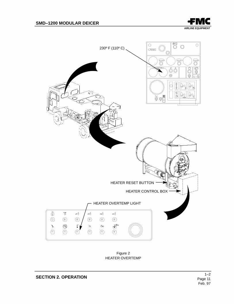
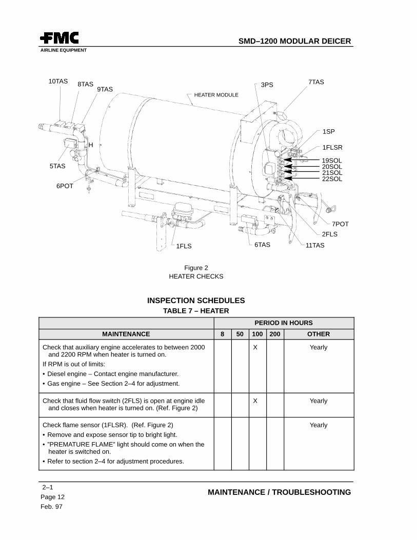
NOTE: If the heater outlet temperature reaches 230º F (110º C) the heater will turn off and theheater ”OVER TEMP” light, located on the front of the heater control box, will illuminate.If this occurs, it will be necessary to manually reset the heater switch by pressing the redbutton located on the heater outlet manifold. If an over temperature condition continuesto shut down the heater, remove the vehicle from service and refer to the maintenancesection for further action.(Ref. Figure 2)
D. Heater Shut Down (manual) (Ref. Figure 1)
To turn off the heater hold the heater switch down until the GREEN LIGHT goes out (white lightwill also go out). The engine will continue to run at 2000 RPM until the purge cycle is complete(approximately 3 minutes).
AFTER TURNING OFF THE HEATER, DO NOT SHUT OFF THE ENGINEUNTIL THE PURGE CYCLE IS COMPLETED.
6. DEICING FLUID DELIVERY PUMP (REF. FIGURE 1)
A. Fluid Pump Controls
The Deicing fluid delivery section of the cab control box consists of a three position toggle switchand a GREEN ”ON” LIGHT. The switch is maintained in its center position and pushedmomentarily up or down for pump operation.
B. Deicing Fluid Pump Operation
(1) To turn on the pump, push the switch up to ”ON” (1) until the green light illuminates, thenrelease the switch. (Engine RPM will increase to 2000 RPM). If fluid is not delivered fromthe basket or ground deicing nozzle for a period of two minutes, the pump willautomatically cycle off and the green light will extinguish.
(2) To turn off the pump during an active cycle, push the switch down and hold until the greenlight goes out.
C. Fluid Level Indication (Optional)
All fluid level indication is done by analog gauges just above the heater section. The unit mayhave a gauge or a combination of gauges depending on the type of unit and options purchased.
D. Low Fluid Warning Lights (Optional)
A red warning light may be installed next to each fluid level gauge to indicate a low fluid levelcondition.
THE EMERGENCY HYDRAULIC PUMP IS NOT GOOD FOR CONTINUOUSUSE. DO NOT USE MORE THAN 60 SECONDS AT A TIME AND ALLOWFIVE MINUTES FOR COOLING TIME BETWEEN USE PERIODS.
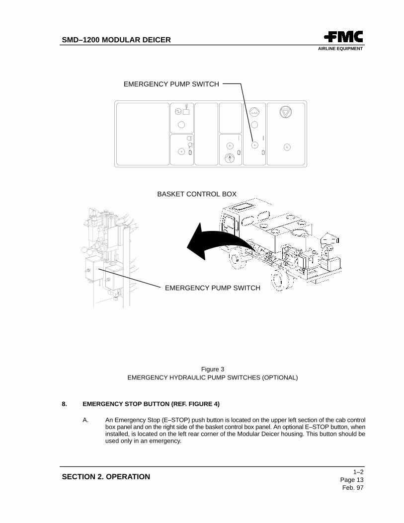
A. Function
An emergency, electrically driven hydraulic pump is provided to operate the boom in the eventof failure of the engine driven hydraulic pump. An optional emergency pump switch is providedon the basket control panel and at the ground control station. This switch should only be usedwhen the engine is not running.
B. Basket Operation
(1) Hold emergency pump switch in ”ON” position.
(2) Move joystick while holding emergency pump switch in ”ON” position.
C. Ground Control Station Operation
(1) Hold emergency pump switch in ”ON” position.
(2) Use Elevation and Rotation levers to operate boom while holding emergency pumpswitch in ”ON” position.
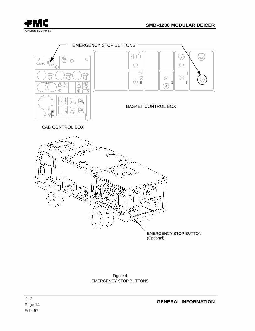
A. An Emergency Stop (E–STOP) push button is located on the upper left section of the cab controlbox panel and on the right side of the basket control box panel. An optional E–STOP button, wheninstalled, is located on the left rear corner of the Modular Deicer housing. This button should beused only in an emergency.
SMD–1200 MODULAR DEICERAIRLINE EQUIPMENT
1–2
Page 14
Feb. 97
GENERAL INFORMATION
CAB CONTROL BOX
BASKET CONTROL BOX
EMERGENCY STOP BUTTONS
EMERGENCY STOP BUTTON(Optional)
Figure 4EMERGENCY STOP BUTTONS
SMD–1200 MODULAR DEICERAIRLINE EQUIPMENT
1–2Page 15Feb. 97
SECTION 2. OPERATION
B. When any of the three E–STOP buttons is pushed, the following occurs:
(1) Control power is turned off for all systems except for lighting.
(2) The auxiliary engine is stopped and the parking brake (European models only) is setif the boom is out of rest.
(3) The red E–STOP light on the cab control box illuminates. This light will illuminate as longas the ignition switch is on.
(4) Engine starting will be prevented until all E–STOP buttons are pulled out.
9. CAB OVERHEAD WIPER CONTROL
A. Wiper Function
The overhead window wiper is a two speed wiper controlled by a three position switch.
B. Wiper Switch Function (Cab Control Panel)
(1) Lower position is ”OFF”
(2) Center position is ”LOW”
(3) Upper position is ”HIGH”
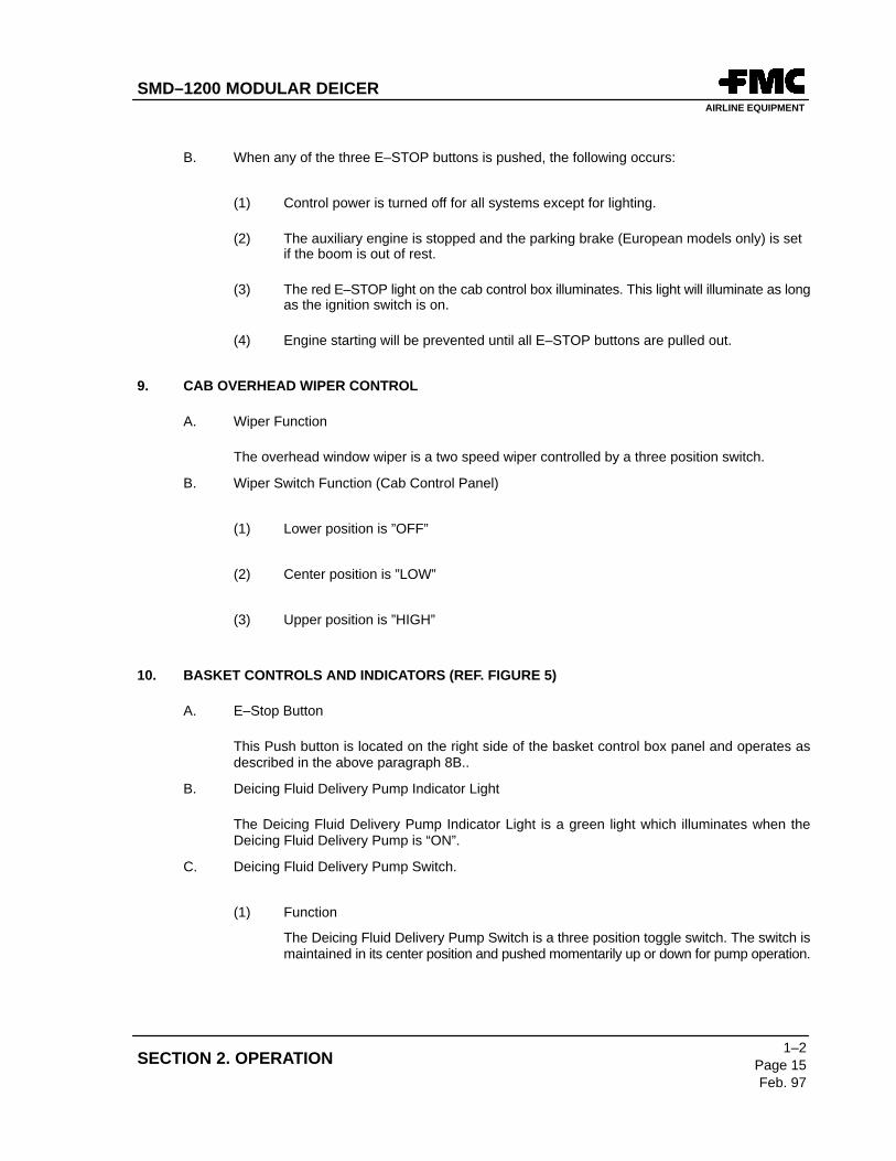
10. BASKET CONTROLS AND INDICATORS (REF. FIGURE 5)
A. E–Stop Button
This Push button is located on the right side of the basket control box panel and operates asdescribed in the above paragraph 8B..
B. Deicing Fluid Delivery Pump Indicator Light
The Deicing Fluid Delivery Pump Indicator Light is a green light which illuminates when theDeicing Fluid Delivery Pump is “ON”.
C. Deicing Fluid Delivery Pump Switch.
(1) Function
The Deicing Fluid Delivery Pump Switch is a three position toggle switch. The switch ismaintained in its center position and pushed momentarily up or down for pump operation.
SMD–1200 MODULAR DEICERAIRLINE EQUIPMENT
1–2
Page 16
Feb. 97
GENERAL INFORMATION
(2) Pump Operation
(a) To turn on the pump, push the switch up to ”ENABLE” until the green lightilluminates, then release the switch. (Engine RPM will increase to 2000 RPM).If fluid is not delivered from the basket or ground deicing nozzle for a period oftwo minutes, the pump will automatically cycle off and the green light willextinguish.
(b) To turn off the pump during an active cycle, push the switch down and hold untilthe green light goes out.
D. Emergency Hydraulic Pump Switch (Optional)
See Item 7. EMERGENCY HYDRAULIC PUMP SWITCH, for description.
E. Light Switch
The basket light switch is a three position switch located on the left side of the basket control boxpanel.
(1) Lower position is ”OFF”
(2) Center position is ”PANEL”
(3) Upper position is ”FLOOD” (Panel lights are also ”ON” in this position.)
F. Joystick Enabled Light
Illuminates when trigger is pulled on joystick to indicate joystick is activated.
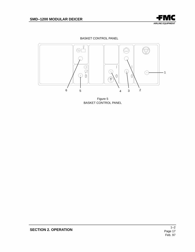
G. Controls and Indicators (REF. FIGURE 5):
(1) E–Stop Button
(2) Deicing Fluid Delivery Pump Indicator Light
(3) Deicing Fluid Delivery Pump Switch
(4) Emergency Hydraulic Pump Switch (Optional)
(5) Light Switch
(6) Joystick Enabled Light
SMD–1200 MODULAR DEICERAIRLINE EQUIPMENT
1–2Page 17Feb. 97
SECTION 2. OPERATION
BASKET CONTROL PANEL
1
26 345
Figure 5BASKET CONTROL PANEL
SMD–1200 MODULAR DEICERAIRLINE EQUIPMENT
1–2
Page 18
Feb. 97
GENERAL INFORMATION
11. AERIAL DEVICE OPERATION
DO NOT OPERATE BOOM/AERIAL DEVICE WHEN WIND SPEED IS ABOVE46 MPH (74 KPH)
A. Boom and Basket Operation
(1) Start Auxiliary engine.
(2) Start Heater if needed.
(3) Start Deicing Fluid Delivery pump.
(4) Enter basket and secure basket latch.
(5) Check intercom operation.
(6) Attach safety harness.
(7) Operate the aerial device using the joystick control. (The red trigger must be depressed).To raise the boom, pull back on the joystick. To lower, push forward. To rotate the aerialdevice, move the joystick right or left.
ALWAYS RAISE THE BOOM A FEW FEET BEFORE ROTATING THE BOOM.FAILURE TO FOLLOW THIS PROCEDURE MAY RESULT IN SEVEREBOOM DAMAGE.
NOTE: A red light located at the top of the cab control box panel illuminates when the boom isout of its rest.
(8) Position the truck and use the joystick control to provide access when deicing. The boomcan be rotated 180º left or right to cover a large area without repositioning the truck.
DO NOT EXCEED 4 MPH (6.5 KM/HR) WITH PERSON IN BASKET.
(9) To stow the aerial device, lower the boom first, then rotate the aerial device to bring thebasket to the front and lower the boom onto the boom rest.
CAUTION
SMD–1200 MODULAR DEICERAIRLINE EQUIPMENT
1–2Page 19Feb. 97
SECTION 2. OPERATION
B. Auxiliary Engine Shutdown (Cab Control Box)
(1) Turn off the heater and deicing fluid delivery pump if they are operating. The engine willcontinue to run at 2000 RPM until purge cycle is completed (approximately threeminutes), then decrease to idle (1000 RPM).
(2) Allow the engine to idle for approximately two minutes to properly cool down.
(3) Turn the ignition switch off.
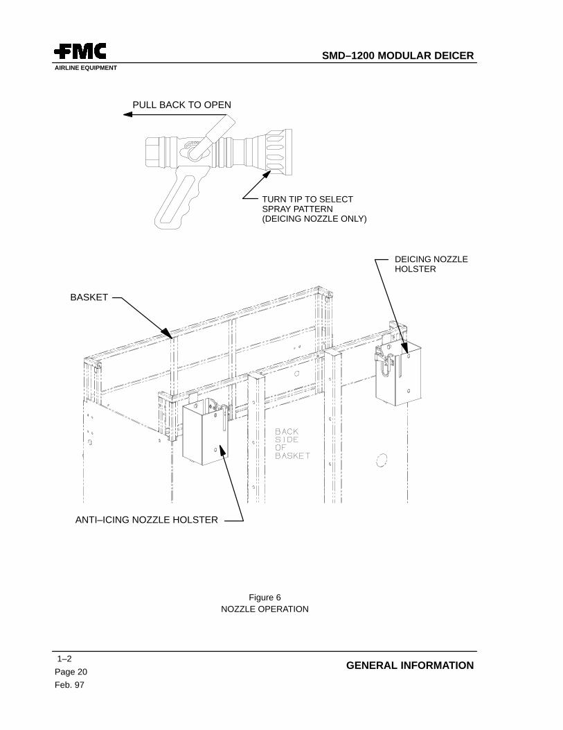
12. DEICING OPERATION (REF. FIGURE 6)
DUE TO THE HIGH TEMPERATURE OF THE DEICING FLUID MIXTURE,THE OPERATOR MUST WEAR PROTECTIVE GLOVES.
A. Deicing Spray Nozzle Operation (Basket)
(1) Remove the nozzle from its holster.
(2) To maintain maximum control of the high pressure nozzle, place the hose under the armand hold the pistol grip with a firm grip.
(3) Adjust the nozzle head for the desired spray pattern.
The spray pattern can be adjusted by turning the black ribbed tip of the nozzle. The spraypattern should be adjusted to maintain adequate deicing depending on the ambientweather conditions.
(4) When in position and nozzle settings are correct, grasp the control handle and pull backto open nozzle.
THE CONTROL HANDLE IS NOT SPRING LOADED. IT MUST BE PUSHEDFORWARD TO TURN THE FLUID FLOW OFF.
NOTE: If control of the nozzle is lost, the nozzle flow can be stopped by pressing the emergencystop button.
CAUTION
CAUTION
SMD–1200 MODULAR DEICERAIRLINE EQUIPMENT
1–2
Page 20
Feb. 97
GENERAL INFORMATION
ANTI–ICING NOZZLE HOLSTER
DEICING NOZZLEHOLSTER
PULL BACK TO OPEN
BASKET
TURN TIP TO SELECTSPRAY PATTERN(DEICING NOZZLE ONLY)
Figure 6NOZZLE OPERATION
SMD–1200 MODULAR DEICERAIRLINE EQUIPMENT
1–2Page 21Feb. 97
SECTION 2. OPERATION
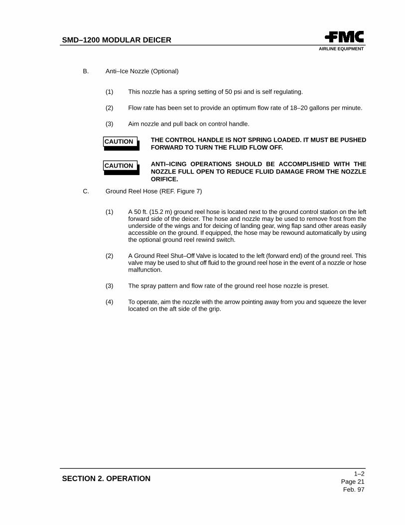
B. Anti–Ice Nozzle (Optional)
(1) This nozzle has a spring setting of 50 psi and is self regulating.
(2) Flow rate has been set to provide an optimum flow rate of 18–20 gallons per minute.
(3) Aim nozzle and pull back on control handle.
THE CONTROL HANDLE IS NOT SPRING LOADED. IT MUST BE PUSHEDFORWARD TO TURN THE FLUID FLOW OFF.
ANTI–ICING OPERATIONS SHOULD BE ACCOMPLISHED WITH THENOZZLE FULL OPEN TO REDUCE FLUID DAMAGE FROM THE NOZZLEORIFICE.
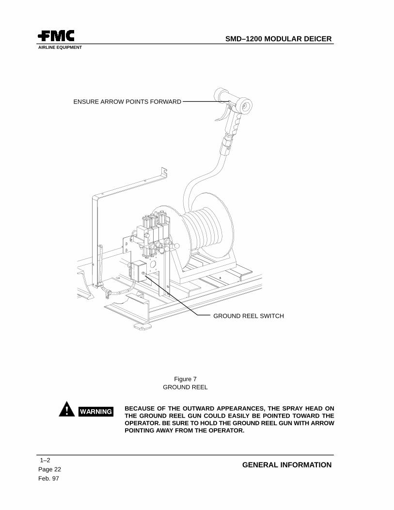
C. Ground Reel Hose (REF. Figure 7)
(1) A 50 ft. (15.2 m) ground reel hose is located next to the ground control station on the leftforward side of the deicer. The hose and nozzle may be used to remove frost from theunderside of the wings and for deicing of landing gear, wing flap sand other areas easilyaccessible on the ground. If equipped, the hose may be rewound automatically by usingthe optional ground reel rewind switch.
(2) A Ground Reel Shut–Off Valve is located to the left (forward end) of the ground reel. Thisvalve may be used to shut off fluid to the ground reel hose in the event of a nozzle or hosemalfunction.
(3) The spray pattern and flow rate of the ground reel hose nozzle is preset.
(4) To operate, aim the nozzle with the arrow pointing away from you and squeeze the leverlocated on the aft side of the grip.
CAUTION
CAUTION
SMD–1200 MODULAR DEICERAIRLINE EQUIPMENT
1–2
Page 22
Feb. 97
GENERAL INFORMATION
ENSURE ARROW POINTS FORWARD
GROUND REEL SWITCH
Figure 7GROUND REEL
BECAUSE OF THE OUTWARD APPEARANCES, THE SPRAY HEAD ONTHE GROUND REEL GUN COULD EASILY BE POINTED TOWARD THEOPERATOR. BE SURE TO HOLD THE GROUND REEL GUN WITH ARROWPOINTING AWAY FROM THE OPERATOR.
SMD–1200 MODULAR DEICERAIRLINE EQUIPMENT
1–2Page 23Feb. 97
SECTION 2. OPERATION
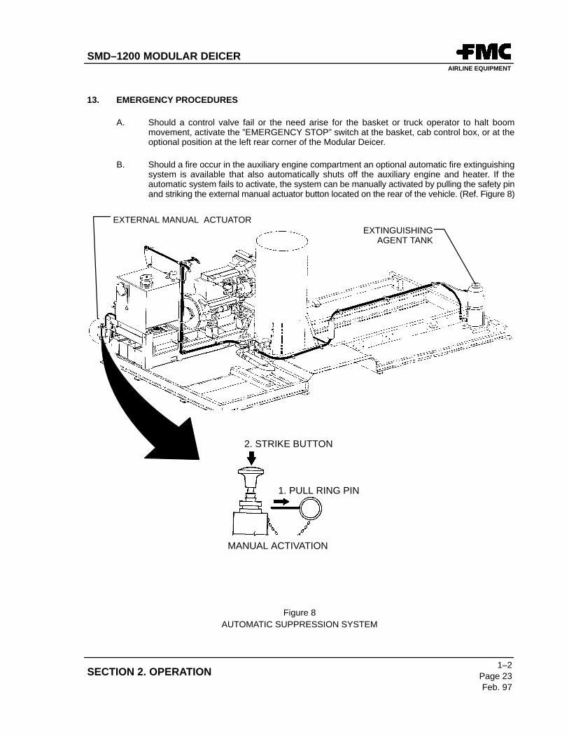
13. EMERGENCY PROCEDURES
A. Should a control valve fail or the need arise for the basket or truck operator to halt boommovement, activate the ”EMERGENCY STOP” switch at the basket, cab control box, or at theoptional position at the left rear corner of the Modular Deicer.
B. Should a fire occur in the auxiliary engine compartment an optional automatic fire extinguishingsystem is available that also automatically shuts off the auxiliary engine and heater. If theautomatic system fails to activate, the system can be manually activated by pulling the safety pinand striking the external manual actuator button located on the rear of the vehicle. (Ref. Figure 8)
2. STRIKE BUTTON
1. PULL RING PIN
MANUAL ACTIVATION
EXTINGUISHINGAGENT TANK
EXTERNAL MANUAL ACTUATOR
Figure 8AUTOMATIC SUPPRESSION SYSTEM
SMD–1200 MODULAR DEICERAIRLINE EQUIPMENT
1–2
Page 24
Feb. 97
GENERAL INFORMATION
C. Emergency Boom Lowering – Hdraulic Pump Failure
An emergency, electrically driven hydraulic pump is provided to operate the boom in the eventof failure of the engine driven hydraulic pump. An optional emergency pump switch is providedon the basket control panel and at the ground control station. This switch should only be usedwhen the engine is not running.
THE EMERGENCY HYDRAULIC PUMP IS NOT GOOD FOR CONTINUOUSUSE. DO NOT USE MORE THAN 60 SECONDS AT A TIME AND ALLOWFIVE MINUTES FOR COOLING TIME BETWEEN USE PERIODS.
(1) Basket Operation
(a) Hold emergency pump switch in ”ON” position.
(b) Move joystick while holding emergency pump switch in ”ON” position.
(2) Ground Control Station Operation
(a) Hold emergency pump switch in ”ON” position.
(b) Use Elevation and Rotation levers to operate boom while holding emergencypump switch in ”ON” position.
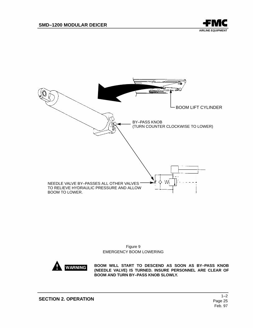
D. Emergency Boom Lowering – No Power (Ref. Figure 9)
(1) Position maintenance stair, if necessary, to provide access to the boom lift cylinder.
(2) Locate by–pass knob (needle valve) on lower left end of boom lift cylinder.
(3) Slowly turn by–pass knob counterclockwise until boom lowers.
(4) Turn by–pass knob clockwise when boom lowering is completed. (Do not over–tighten.)
DO NOT OVER–TIGHTEN. OVER–TIGHTING WILL DAMAGE THE SEALON THE BYPASS VALVE.
CAUTION
CAUTION
SMD–1200 MODULAR DEICERAIRLINE EQUIPMENT
1–2Page 25Feb. 97
SECTION 2. OPERATION
BY–PASS KNOB(TURN COUNTER CLOCKWISE TO LOWER)
NEEDLE VALVE BY–PASSES ALL OTHER VALVES TO RELIEVE HYDRAULIC PRESSURE AND ALLOWBOOM TO LOWER.
BOOM LIFT CYLINDER
Figure 9EMERGENCY BOOM LOWERING
BOOM WILL START TO DESCEND AS SOON AS BY–PASS KNOB(NEEDLE VALVE) IS TURNED. INSURE PERSONNEL ARE CLEAR OFBOOM AND TURN BY–PASS KNOB SLOWLY.
SMD–1200 MODULAR DEICERAIRLINE EQUIPMENT
1–2
Page 26
Feb. 97
GENERAL INFORMATION
14. REFILL PROCEDURES (REF. FIGURE 10)
A. Pressure Refill
(1) Deicing Fluid (Type I)
Deicing fluid is pressure refilled through either the “DEICING SUCTION / PRESSUREREFILL CONNECTION” port forward of the Deicing Delivery Pump in the right sidecompartment, or the “DEICING PRESSURE REFILL CONNECTION” port in the lefthand compartment aft of the hose reel.
NOTE: The “DEICING PRESSURE REFILL CONNECTION” port in the left hand compartmentis also used for draining the Deicing fluid tank. This port does not contain a check valveand fluid remaining in the Deicing tank will drain when the port drain valve is opened.During refilling, fluid in the tank will back flow to the filling source if the supply source isnot pressurized.
CAUTION SHOULD BE EXERCISED IF THE TANK CONTAINS HOT FLUID.
(2) Anti–Icing Fluid (Type II) (Optional)
Anti–icing fluid is pressure refilled through the “ANTI–ICING SUCTION /PRESSUREREFILL CONNECTION” port on the anti–icing pump in the left side compartment.
(3) Pressure Refill Steps
(a) Deicing Fluid – Pressure Refill
1) Remove dust cap (if equipped) on the refill port.
2) With the locking levers fully extended, push the hose coupling onto therefill port and, when seated, force the levers inward to lock in place.
3) Open the valve on the refill port.
If using the “DEICING SUCTION/PRESSURE REFILL CONNECTION”port, open the “DEICING SUCTION REFILL VALVE” located above therefill port. The valve handle points down when in the “open” position.(This valve remains in the “Closed” position for normal operation.)
If using the “DEICING PRESSURE REFILL CONNECTION” port, openthe “DEICING DRAIN VALVE”. (The valve handle points toward theoperator when in the open position.)
4) Open hose valve to begin refilling.
5) Observe sight gauge on the left forward corner of the tank and, whenfull, close hose valve.
SMD–1200 MODULAR DEICERAIRLINE EQUIPMENT
1–2Page 27Feb. 97
SECTION 2. OPERATION
6) Close the “DEICING DRAIN VALVE”. (This valve remains closed fornormal operation.) If using the “DEICING SUCTION REFILL VALVE”,leave the valve handle in the “Closed” position.
7) Open locking handles and remove hose. (Fluid trapped between thevalves will spill when the hose connection is removed.)
8) Reattach refill port dust cap.
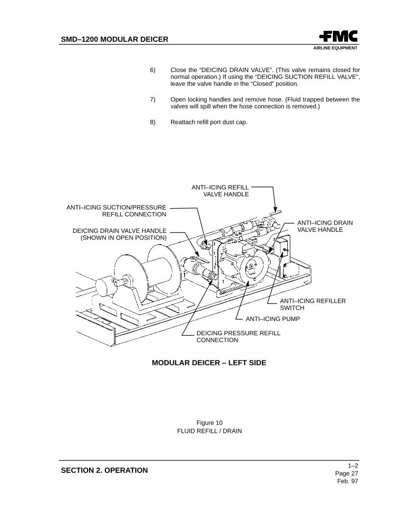
MODULAR DEICER – LEFT SIDE
DEICING DRAIN VALVE HANDLE(SHOWN IN OPEN POSITION)
DEICING PRESSURE REFILLCONNECTION
ANTI–ICING PUMP
ANTI–ICING REFILLERSWITCH
ANTI–ICING DRAINVALVE HANDLE
ANTI–ICING SUCTION/PRESSUREREFILL CONNECTION
ANTI–ICING REFILLVALVE HANDLE
Figure 10FLUID REFILL / DRAIN
SMD–1200 MODULAR DEICERAIRLINE EQUIPMENT
1–2
Page 28
Feb. 97
GENERAL INFORMATION
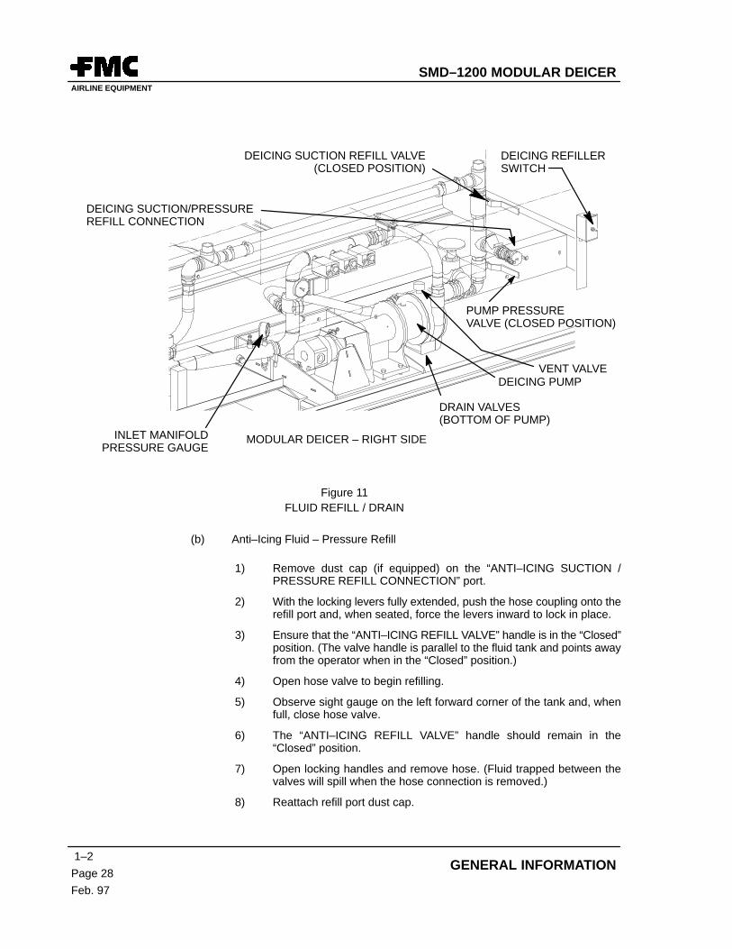
MODULAR DEICER – RIGHT SIDE
DEICING PUMP
DEICING REFILLERSWITCH
DEICING SUCTION/PRESSUREREFILL CONNECTION
DEICING SUCTION REFILL VALVE(CLOSED POSITION)
VENT VALVE
DRAIN VALVES(BOTTOM OF PUMP)
INLET MANIFOLDPRESSURE GAUGE
PUMP PRESSUREVALVE (CLOSED POSITION)
Figure 11FLUID REFILL / DRAIN
(b) Anti–Icing Fluid – Pressure Refill
1) Remove dust cap (if equipped) on the “ANTI–ICING SUCTION /PRESSURE REFILL CONNECTION” port.
2) With the locking levers fully extended, push the hose coupling onto therefill port and, when seated, force the levers inward to lock in place.
3) Ensure that the “ANTI–ICING REFILL VALVE” handle is in the “Closed”position. (The valve handle is parallel to the fluid tank and points awayfrom the operator when in the “Closed” position.)
4) Open hose valve to begin refilling.
5) Observe sight gauge on the left forward corner of the tank and, whenfull, close hose valve.
6) The “ANTI–ICING REFILL VALVE” handle should remain in the“Closed” position.
7) Open locking handles and remove hose. (Fluid trapped between thevalves will spill when the hose connection is removed.)
8) Reattach refill port dust cap.
SMD–1200 MODULAR DEICERAIRLINE EQUIPMENT
1–2Page 29Feb. 97
SECTION 2. OPERATION
B. Suction (Pump)Refill
(1) Deicing Fluid
Deicing fluid is suction refilled through the “DEICING SUCTION/PRESSURE REFILLCONNECTION” port located forward of the Deicing Delivery Pump in the right sidecompartment.
(2) Anti–Icing Fluid
Anti–icing fluid is suction refilled through the “ANTI–ICING SUCTION /PRESSUREREFILL CONNECTION” port on the anti–icing pump in the left side compartment.
(3) Suction Refill Steps
(a) Deicing Fluid –Suction Refill
1) Start auxiliary engine.
2) Remove dust cap (if equipped) on the “DEICING SUCTION /PRESSURE REFILL CONNECTION” port.
3) With the locking levers fully extended, push the hose coupling ontothe“DEICING SUCTION/PRESSURE REFILL CONNECTION” portand, when seated, force the levers inward to lock in place.
4) Open the “DEICING SUCTION REFILL VALVE”. (The valve handlepoints down when in the “Open” position.)
5) Push and hold the “DEICING REFILLER” switch in the “ON” position.(Pump will start and run)
6) Open the “PUMP PRESSURE VALVE” located under the “DEICINGSUCTION / PRESSURE REFILL CONNECTION”. (Valve handle pointsdown when in the “Open” position.)
7) Observe sight gauge on the left forward corner of the tank and, whenfull, release “DEICING REFILLER” switch to the “OFF” position.
8) Close the “PUMP PRESSURE VALVE” (The valve handle is horizontalwhen in the “Closed” position.)
9) Close the “DEICING SUCTION REFILL VALVE”. (The valve handle ishorizontal when in the “Closed” position.)
10) Close hose valve and remove hose.
11) Reattach refill port dust cap.
SMD–1200 MODULAR DEICERAIRLINE EQUIPMENT
1–2
Page 30
Feb. 97
GENERAL INFORMATION
(b) Anti–Icing Fluid – Suction Refill
1) Start auxiliary engine.
2) Remove dust cap (if equipped) on the ”ANTI–ICING SUCTION/PRESSURE REFILL CONNECTION” port.
3) With the locking levers fully extended, push the hose coupling onto therefill port and, when seated, force the levers inward to lock in place.
4) Open the “ANTI–ICING REFILL VALVE” by pulling out on the“ANTI–ICING REFILL VALVE” handle. (Handle points toward theoperator when in the open position.) This will activate the Anti–icingpump and it will pump at 20 gpm.
5) If the Anti–Icing pump does not run or a faster refill rate is desired, anoptional “ANTI–ICING REFILLER” switch is located to the right of thepump. It may be used to operate the pump as follows:
� Push and hold the “ANTI–ICING REFILLER” switch in the “ON”position. (Pump will start or increase in speed up to amaximum of 60 gpm.)
� Release “ANTI–ICING REFILLER” switch to the “OFF” positionwhen refilling is complete.
6) Observe sight gauge on the left forward corner of the tank and, whenfull, close hose valve.
7) Return the “ANTI–ICING REFILL VALVE” handle to the “Closed”position.
8) Ensure that Anti–icing pump has stopped.
9) Open locking handles and remove hose. (Fluid trapped between thevalves will spill when the hose connection is removed.)
10) Reattach refill port dust cap.
C. Top Refill
The fluid tanks can also be filled using an overhead drop pipe or hose. The tanks are fitted withquick opening covers that can be removed for filling.
DURING TOP FILLING, FLUIDS MAY BE SPILLED ON THE WALKWAYCREATING A HAZARD. EXTREME CAUTION SHOULD BE EXERCISEDDURING TOP FILLING OPERATIONS.
(1) Open spring loaded latch on top fill cover and lift cover.
(2) Swing drop pipe or hose into position and fill as required.
(3) After filling is complete close cover and insure spring loaded latch is secure.
SMD–1200 MODULAR DEICERAIRLINE EQUIPMENT
1–2Page 31Feb. 97
SECTION 2. OPERATION
15. DRAIN/PURGE PROCEDURE (REF FIGURE 11)
THE DEICING FLUID PUMP AND THE HEATER MUST BE TURNED OFFPRIOR TO DRAINING OR PURGING.
A. Deicing (Type I) Drain Procedure
(1) Move the unit to a location where glycol can be dispersed.
(2) Open the Deicing nozzle in the basket.
(3) Raise the boom five to ten degrees above the horizontal.
(4) Open the Deicing Drain Valve and drain as much fluid as possible. (Drain Valve handlepoints toward the operator when in the open position.)
(5) Open both drain valves and the vent valve on the Deicing pump (Ref. Figure 11).
(6) Open the drain valve on the heater inlet and outlet manifolds and drain as much fluid aspossible (Ref. Figure 12).
NOTE: The heater, pump and ground reel hose will not drain completely. Some fluid will backdrain from the boom nozzle and plumbing.
(7) Remove the plug or open the valve (if equipped) on the tank sump underneath thedeicing tank.
(8) Close all drains and nozzle when fluid drain is complete.
B. Anti–Icing (Type II) Drain Procedure
(1) Move the unit to a location where glycol can be dispersed.
(2) Open the Anti–icing nozzle in the basket.
(3) Raise the boom five to ten degrees above the horizontal.
(4) Open the Anti–Icing Drain Valve (located to the right of the Anti–icing pump) and drainas much fluid as possible. (Drain Valve handle points toward the operator when in theopen position.)
NOTE: Pump will not drain completely.
(5) Close all drains and nozzle when fluid drain is complete.
SMD–1200 MODULAR DEICERAIRLINE EQUIPMENT
1–2
Page 32
Feb. 97
GENERAL INFORMATION
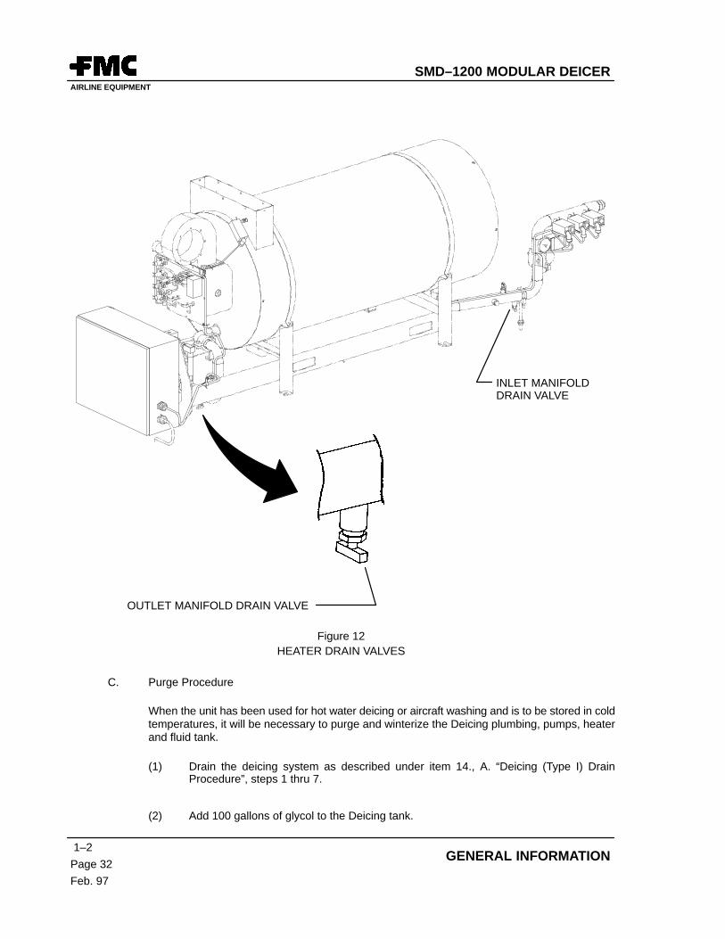
OUTLET MANIFOLD DRAIN VALVE
INLET MANIFOLDDRAIN VALVE
Figure 12HEATER DRAIN VALVES
C. Purge Procedure
When the unit has been used for hot water deicing or aircraft washing and is to be stored in coldtemperatures, it will be necessary to purge and winterize the Deicing plumbing, pumps, heaterand fluid tank.
(1) Drain the deicing system as described under item 14., A. “Deicing (Type I) DrainProcedure”, steps 1 thru 7.
(2) Add 100 gallons of glycol to the Deicing tank.
SMD–1200 MODULAR DEICERAIRLINE EQUIPMENT
1–2Page 33/(34 blank)
Feb. 97
SECTION 2. OPERATION
(3) Start the power module auxiliary engine and run at slow speed.
(4) Open the vent valve on top of the Deicing Pump.
(5) Close vent valve when a steady flow of glycol flows from the vent.
(6) Turn on the Deicing Pump by pressing and holding the “DEICING (Type 1) REFILLER”switch or by using the Deicing Pump switch on the cab control panel.
(a) If the Inlet Manifold Pressure Gauge indicates more than 75 psi, proceed to Step 7.
(b) If the pressure does not rise, turn the pump off and open the vent valve until asteady stream of glycol is visible. Close valve and repeat step (6).
(7) Run the delivery pump five to ten minutes to purge the heater.
(8) Open the heater “INLET MANIFOLD DRAIN VALVE” slightly and take a sample.
(9) Using a Refractometer, check to be sure the freeze point is sufficiently low for theexpected conditions.
(10) Add glycol if necessary and repeat steps 7, 8, 9 and 10 until freeze point is sufficientlylow.
(11) Lower the boom to the rest position.
(12) Turn on the Deicing delivery pump.
(13) Open the ground reel nozzle and spray until fresh fluid is visible.
(14) Check with Refractometer if in doubt.
(15) When satisfied with Deicing fluid freeze point, close the nozzle and store.
(16) At the basket nozzle, open the control handle and hold open until fresh fluid is visible.
(17) Check with Refractometer if in doubt.
(18) When satisfied with Deicing fluid freeze point, close the nozzle and store.
(19) Turn off the Deicing Delivery Pump.
SMD–1200 MODULAR DEICERAIRLINE EQUIPMENT
1–3Page 1Feb. 97
SECTION 3. CHASSIS SPECIFICATIONS
Section 3. Chassis Specifications
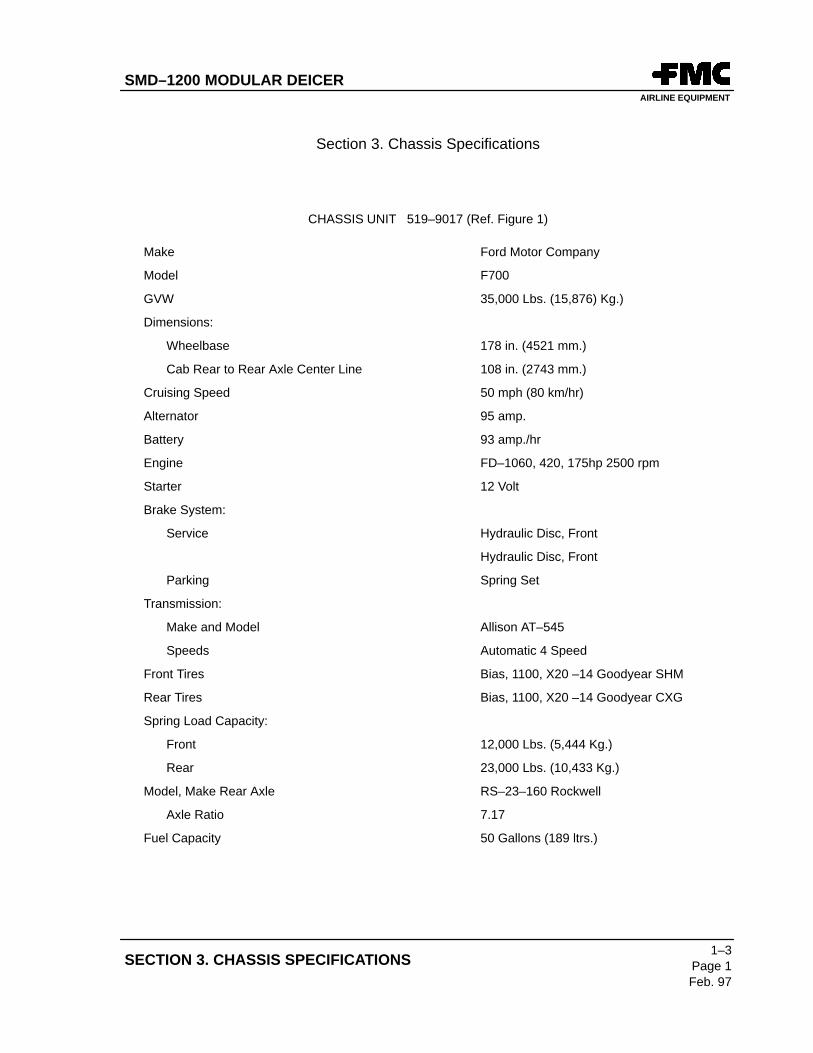
CHASSIS UNIT 519–9017 (Ref. Figure 1)
Make Ford Motor Company
Model F700
GVW 35,000 Lbs. (15,876) Kg.)
Dimensions:
Wheelbase 178 in. (4521 mm.)
Cab Rear to Rear Axle Center Line 108 in. (2743 mm.)
Cruising Speed 50 mph (80 km/hr)
Alternator 95 amp.
Battery 93 amp./hr
Engine FD–1060, 420, 175hp 2500 rpm
Starter 12 Volt
Brake System:
Service Hydraulic Disc, Front
Hydraulic Disc, Front
Parking Spring Set
Transmission:
Make and Model Allison AT–545
Speeds Automatic 4 Speed
Front Tires Bias, 1100, X20 –14 Goodyear SHM
Rear Tires Bias, 1100, X20 –14 Goodyear CXG
Spring Load Capacity:
Front 12,000 Lbs. (5,444 Kg.)
Rear 23,000 Lbs. (10,433 Kg.)
Model, Make Rear Axle RS–23–160 Rockwell
Axle Ratio 7.17
Fuel Capacity 50 Gallons (189 ltrs.)
SMD–1200 MODULAR DEICERAIRLINE EQUIPMENT
1–3
Page 2
Feb. 97
GENERAL INFORMATION
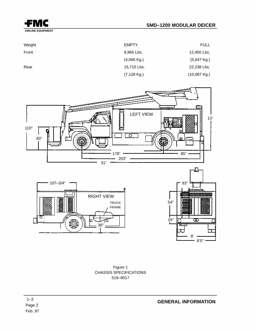
Weight EMPTY FULL
Front 8,965 Lbs. 12,450 Lbs.
(4,066 Kg.) (5,647 Kg.)
Rear 15,715 Lbs. 22,238 Lbs.
(7,128 Kg.) (10,087 Kg.)
LEFT VIEW
RIGHT VIEWTRUCKFRAME
107–3/4”
31”203”
178” 85”
13’
60”
110”
36”
93”
54”
16”
8’8’5”
Figure 1CHASSIS SPECIFICATIONS
519–9017
SMD–1200 MODULAR DEICERAIRLINE EQUIPMENT
1–4Page 1Feb. 97
SECTION 4. MODULAR DEICER UNIT SPECIFICATIONS
Section 4. Modular Deicer Unit Specifications
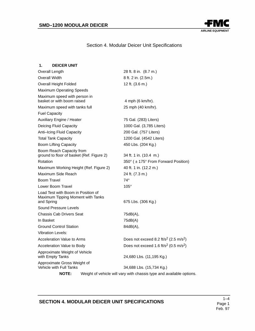
1. DEICER UNIT
Overall Length 28 ft. 8 in. (8.7 m.)
Overall Width 8 ft. 2 in. (2.5m.)
Overall Height Folded 12 ft. (3.6 m.)
Maximum Operating Speeds
Maximum speed with person in basket or with boom raised 4 mph (6 km/hr).
Maximum speed with tanks full 25 mph (40 km/hr).
Fuel Capacity
Auxiliary Engine / Heater 75 Gal. (283) Liters)
Deicing Fluid Capacity 1000 Gal. (3,785 Liters)
Anti–Icing Fluid Capacity 200 Gal. (757 Liters)
Total Tank Capacity 1200 Gal. (4542 Liters)
Boom Lifting Capacity 450 Lbs. (204 Kg.)
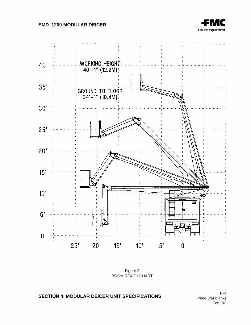
Boom Reach Capacity from ground to floor of basket (Ref. Figure 2) 34 ft. 1 in. (10.4 m.)
Rotation 350° ( ± 175° From Forward Position)
Maximum Working Height (Ref. Figure 2) 40 ft. 1 in. (12.2 m.)
Maximum Side Reach 24 ft. (7.3 m.)
Boom Travel 74°Lower Boom Travel 105°Load Test with Boom in Position ofMaximum Tipping Moment with Tanksand Spring 675 Lbs. (306 Kg.)
Sound Pressure Levels
Chassis Cab Drivers Seat 75dB(A),
In Basket 75dB(A)
Ground Control Station 84dB(A),
Vibration Levels:
Acceleration Value to Arms Does not exceed 8.2 ft/s2 (2.5 m/s2)
Acceleration Value to Body Does not exceed 1.6 ft/s2 (0.5 m/s2)
Approximate Weight of Vehiclewith Empty Tanks 24,680 Lbs. (11,195 Kg.)
Approximate Gross Weight of Vehicle with Full Tanks 34,688 Lbs. (15,734 Kg.)
NOTE: Weight of vehicle will vary with chassis type and available options.
SMD–1200 MODULAR DEICERAIRLINE EQUIPMENT
1–4
Page 2
Feb. 97
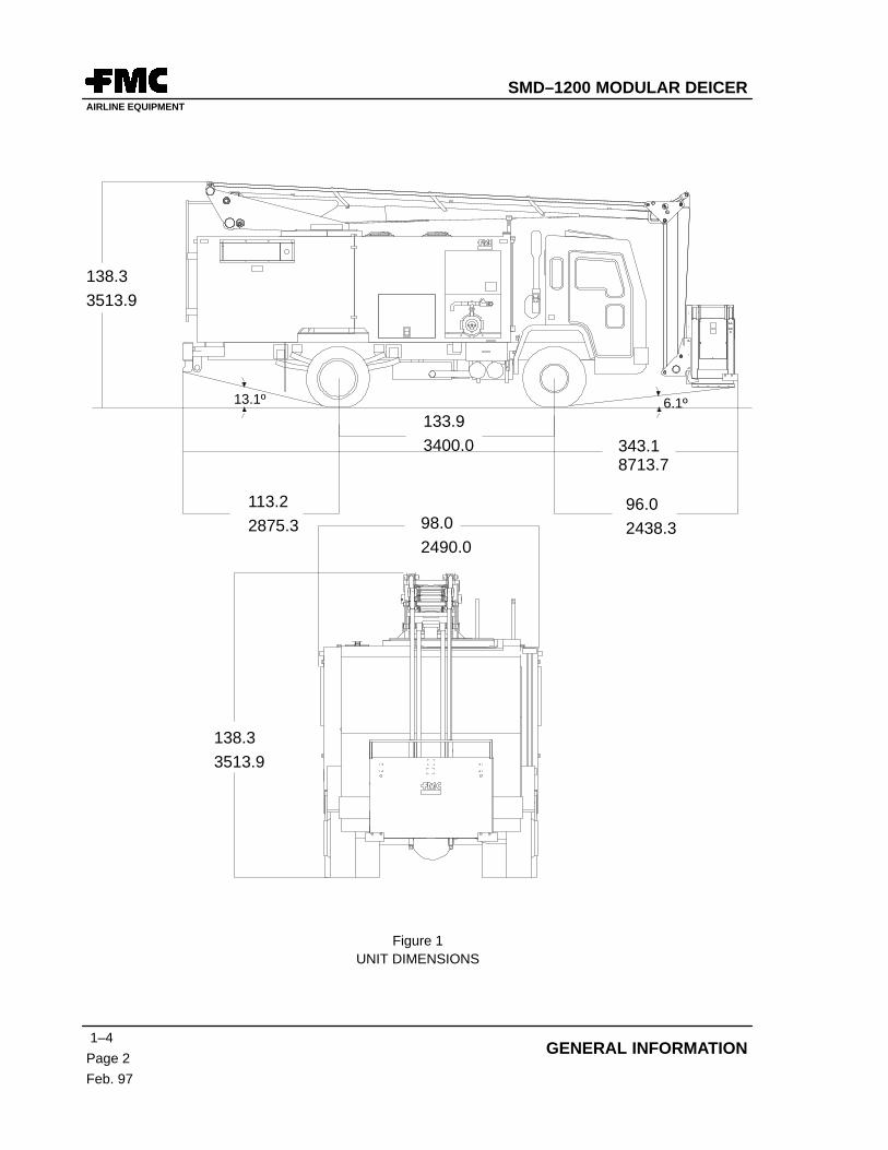
GENERAL INFORMATION
133.9
3400.0
138.3
3513.9
343.1 8713.7
6.1º13.1º
113.2
2875.396.0
2438.398.0
2490.0
138.3
3513.9
Figure 1UNIT DIMENSIONS
SMD–1200 MODULAR DEICERAIRLINE EQUIPMENT
1–4Page 3/(4 blank)
Feb. 97
SECTION 4. MODULAR DEICER UNIT SPECIFICATIONS
Figure 2BOOM REACH CHART
SMD–1200 MODULAR DEICERAIRLINE EQUIPMENT
1–5Page 1Feb. 97
SECTION 5. OPTIONAL CONTROL FEATURES
Section 5. Optional Control Features
1. GROUND REEL
A two position switch located with box and placed on the left side of the deicer by the boom valves. Momentaryswitch that rewinds the ground hose once switch is held. Activate at all times whether auxiliary engine is runningor not.
2. EMERGENCY PUMP SWITCH
This switch is located on the basket control box and by the boom valves. It is used in case of engine failure tosupply hydraulic oil and control power so that boom valves can manually be used to lower the boom back to itsrest. This pump must not be operated for more than 60 seconds at a time. At least five minutes must be allowedfor cooling time between use periods.
3. E–STOP – LEFT REAR
Provides an additional E–stop switch on the rear of the machine.
4. DEICING REFILLER SWITCH
Located on right side toward front of tank, beside pump. A two position switch that, when held to the “ON” position,turns on the deicing pump. (Circulating pump on European models.)
5. ANTI–ICING REFILLER SWITCH
Located on left side of machine by anti–ice pump. A two position switch that turns off the anti–ice pump and turnson the Refiller when held in the “ON” position.
6. BOOM CONTROL LOCKOUT
Provides an interlock that inhibits the basket controls unless a door is closed around the manual boom levers.
7. BATTERY DISCONNECT SWITCH
Provides isolators of both positive and negative from the 24V auxiliary engine batteries. Designed so that levermust be installed and turned in order for machine to work. Once disabled, lever maybe removed so that no oneelse can turn system on.
8. WINTERIZATION KIT, (DIESEL ENGINE)
This kit utilizes external and internal (battery) power sources for the following components:
ENSURE DEICER BODY ACCESS DOORS ARE FIRMLY SECURED IN THEOPEN POSITION WHEN ACCESSING CONTROLS AND EQUIPMENT.
1. INTRODUCTION
Periodic maintenance procedures for the TRUMP Modular Deicer are outlined in tabular form in this section.Frequency requirements for each operation are given in running hours and in calendar time when applicable.A separate Lubrication and Refill Chart is provided for easy reference.
A. Individual Manufacturer’s Instruction Servicing Schedule
(1) Servicing of vehicle engine and running gear should be done in compliance withmanufacturer’s recommended schedule.
(2) Servicing of auxiliary engine and chassis engine components should be done incompliance with manufacturer’s schedule.
(3) Heater Servicing – Refer to paragraph 3 and paragraph 4 of this chapter. Furtherservicing and investigation of specific problems not covered in these paragraphs shouldbe performed by a qualified service technician.
(4) Deicing and Anti–icing pump servicing – The pumps should be serviced asrecommended by Myers and Hardi.
(5) Automatic Fire Extinguishing System (Optional) – The fire extinguishing system is anAnsul, Dry Chemical, A–101 and should be serviced as recommended by Ansul.
B. Fluid System Drain and Purge (See Section1–2, para. 15. DRAIN/PURGE PROCEDURE)
NOTE: In the event of unit major overhaul, servicing, or de–commissioning, any environmentallysensitive materials must be disposed of properly. Proper disposal shall follow localenvironmental regulations and recommendations. Examples of such materials include:rubber tires and belts, batteries, lubricants (motor oils and grease), hydraulic oil, all typesof glycol, insulating material and fuel.
SMD–1200 MODULAR DEICERAIRLINE EQUIPMENT
2–1
Page 2
Feb. 97
MAINTENANCE / TROUBLESHOOTING
2. FLUID SYSTEM DESCRIPTION
A. Deicing Fluid Delivery Pump
Located in the right hand side compartment, this pump circulates fluid through the heater andmaintains a constant system pressure. This pressure is regulated by the pump speed and thesystem relief valve located on the heater outlet manifold. The pump supplies sufficient flow of hotfluid to both the ground reel nozzle and the basket Deicing nozzle.
The Deicing pump is an iron bodied, two stage centrifugal pump incorporating a mechanical shaftfluid seal. The pump is supported by grease lubricated ball bearings and requires littlemaintenance. Power is supplied by an hydraulic motor attached to the pump shaft through a softcoupling. The pump speed is relatively constant and can be changed or adjusted with a flowcontrol valve located on the main hydraulic manifold.
B. Anti–Icing Delivery Pump
Located in the left hand side compartment. This pump will deliver anti–icing fluid to the basketnozzle on demand. This pump is set to a maximum flow rate of 15 (56.5 liters/min) to 30 gpm(113.5 liters/min) to reduce fluid damage during passage through the nozzle. Flow rate is variableup to the maximum setting and is controlled by the nozzle valve. A fully open nozzle isrecommended for anti–icing operations with the pump speed set to control a “NOT TO EXCEED”flow rate. The pump is an iron bodied radial design incorporating six diaphragm chambersoperating in a parallel flow path. Each chamber includes an inlet and outlet check valvecontrolling the flow direction through the pump. The diaphragms are operated by push rodsconnected to a cam on the drive shaft. This arrangement allows the pump to run either directionwithout affecting the direction of the fluid through the pump. Power is supplied by a hydraulicmotor attached to the back of the pump bracket and connected with a 3 – jaw soft coupling. Thepump “NOT TO EXCEED” flow rate of 15–30 gpm is controlled by the motor speed. The motorspeed can be changed by adjusting an hydraulic flow control valve located on the main hydraulicmanifold attached to the pedestal in the rear engine compartment. Optionally, this pump can beused to refill the anti–icing fluid reservoir as a suction refilling station. When used as a refillstation, additional hydraulic valves are supplied to allow a faster pump speed for refilling at upto 60 gpm. Additionally, a speed sensor can be added to this pump to supply a remote signalreadout to indicate the volume of anti–icing fluid delivered.
C. Anti–Icing Fluid Delivery Counters (optional)
The use of high volumetric efficiency fluid pumps allow a simple way of measuring nominal fluiddelivery. When installed, a simple high speed sensor is attached to a delivery pump and countspump revolutions. This data is sent to a counter head located at a remote location, usually thedriver’s compartment. The counter data is converted to US gallons or liters and displayed on adigital readout. The display unit includes a reset button for tracking a single aircraft deicingoperation or can be used for total fluid dispensed over any period required. When used inconjunction with a station refiller, the volume of fluid transferred can be tracked.
SMD–1200 MODULAR DEICERAIRLINE EQUIPMENT
2–1Page 3Feb. 97
SECTION 1. SERVICING
D. Ground Reel & Nozzle
Located in the forward left side compartment, the reel supplies deicing fluid through a standard50 ft. (15.2 m) hose and nozzle. The nozzle is non–adjustable and incorporates a pistol grip withlever to open the internal valve. Delivery flow rate is controlled by the valve lever. When fullydepressed, it will deliver approximately 25 US gpm (113 liters/min) Others nozzles may beinstalled and usually operate in a similar fashion. A hand crank is supplied to assist in rewindingthe hose after use. The reel may include an optional electric motor to speed rewinding. Whenequipped with a motor, a switch is located ahead of the reel for actuation.
E. Deicing Nozzle (Basket)
A nozzle is supplied that allows the operator to dispense deicing fluid in any reasonable directionfrom the basket. It is normally a hand held pistol grip type with an open–close lever on top andequipped with a selector ring for different flow rate settings. The nozzle is connected to a hoseextending from the aerial boom allowing the operator to move freely. The deicing fluid flow rateis variable and controlled by a nozzle valve opening and ring setting, when fully open,approximately 60 US gpm (227 liters/min) is available. Various nozzles may be installed fordifferent situations, or they may be mounted on rigid plumbing (turret). A holster or receptacleis provided for hand held nozzles and includes a rubber hold down latch.
F. Anti–Icing Nozzle (Basket)
When an anti–icing system is installed, a small hand held nozzle is located in the basket. Thismay be an FMC 785 style gun with a pistol grip and a trigger controlled valve. This nozzle isconnected to a hose extending from the aerial boom and allows the operator to move freely. The785 nozzle allows a delivery rate up to 25 US gpm (113 liters/min). Other nozzles may be suppliedfor this operation and operate similarly. A fully open nozzle will generally reduce fluid damageduring anti–icing operations. A holster or receptacle is provided and includes a rubber hold downlatch.
G. Fluid Reservoir
This reservoir will hold a maximum of 1200 US gallons (4540) liters) combined deicing or deicingand anti–icing fluid. The tank is constructed from stainless steel with access covers for cleaning.The forward sections contain deicing fluid and the aft section will contain anti–icing fluid whenincluded. The tank outlet ports include gate valves for service and 1/4 turn ball valves for refilland drains. The forward compartment contains a sump for maximum fluid usability. A sidemounted port and valve is supplied for rapid draining of the deicing fluid and a similar valve issupplied for the aft anti–icing tank when appropriate.
H. Heater Inlet Manifold
Located in the right hand side compartment extending forward of the heater. This manifoldtransfers fluid from the deicing pump to the heater and contains several temperature switchesto monitor incoming fluid for heater operation. A pressure gauge and a temperature gauge isinstalled. An additional port is present for an optional remote temperature sender.
SMD–1200 MODULAR DEICERAIRLINE EQUIPMENT
2–1
Page 4
Feb. 97
MAINTENANCE / TROUBLESHOOTING
I. Heater Outlet Manifold
Located at the rear of the heater under the burner assembly. This manifold contains a flow switch,pressure gauge, temperature gauge, temperature cycle switch and over temperature switch. Theflow switch monitors fluid flow through the heater and will not allow the heater to operate ifinsufficient flow is detected. The cycle switch modulates the burners to keep the outlettemperature as even as possible. The heater over temperature switch will turn the heater off ifthe outlet fluid becomes too hot. A manual reset button is supplied and the heater cannot berestarted until it has been reset. A system relief valve is attached to this manifold and regulatesthe Deicing system pressure.
J. Deicing Fluid Flow Switch & Timer
Located at the base of the pedestal and near the heater, this flow switch will monitor deicing fluiddelivery. If fluid flow is detected, the delivery pump will continue to run. If fluid flow stops, a timeris activated and will count down for two minutes after which the delivery pump will stop. If fluidflow is detected anytime during the two minute period, the timer will reset and wait for anotherno flow condition. If the pump stops, it can be restarted by actuating a switch in the basket.
K. Deicing Refill Stations For Suction Refilling
A deicing fluid refill station is installed just forward of the deicing pump located in the right sidecompartment. This station allows an external pressurized or non–pressurized fluid to be pumpedinto the deicing reservoir. A switch is located near the external hose connection to start the pumpfor suction refilling.
L. Anti–Icing Refill Station For Suction Refilling
An Anti–Icing refill station is installed on the anti–icing pump located in the left side compartment.This station allows an external pressurized or non–pressurized fluid to be pumped into theanti–icing reservoir. A lever is located on top of the pump manifolds to direct the fluid to thereservoir. A switch is located near the external hose connection to start the pump for sectionrefilling.
M. Deicing Pressure Fill Station
Located in the left side compartment, aft of the ground reel, this port normally serves as a rapiddrain for the deicing fluid. When quick connect type hose couplings are installed, the deicingreservoir can be filled from any pressurized source.
N. Fluid Thermal Relief Valve
A small relief valve is attached to the anti–icing pump. This valve relieves the fluid thermalpressure rise when the unit is not in operation.
O. Heater Safety Relief Valve
This valve is located in the heater inlet manifold and is for the explicit purpose of relieving a rapidpressure rise if other heater safety systems fail to operate. This valve is sometimes required bylocal or other safety regulations.
P. Pressure Gauges
A pressure gauge is located on the heater inlet manifold and on the heater outlet manifold. Thesegauges indicate system pressure at that point and are used for adjustment and service.
SMD–1200 MODULAR DEICERAIRLINE EQUIPMENT
2–1Page 5Feb. 97
SECTION 1. SERVICING
Q. Heater Outlet Temperature Gauge
Mechanical temperature gauges are installed in the heater inlet and outlet manifolds. Theyindicate the fluid temperature at that point and are used for adjustment and service.
R. Rotator Fluid Swivels
A rotary swivel is located in the rotator to transfer deicing fluid from the lower chassis plumbingto the rotating aerial boom and basket. A similar swivel is included when an anti–icing systemis present. They can be easily removed for servicing. Grease zerks are installed for periodiclubrication.
S. Test Ports On Pump Outlet Manifolds
Test ports are present on the heater inlet and outlet manifolds as well as the delivery pumpmanifolds for external pressure or temperature sensing. They are plugged for normal operation.
3. INSPECTION SCHEDULES
INSPECTION SCHEDULESTABLE 1 – VEHICLE
PERIOD IN HOURS
MAINTENANCE 8 50 100 200 OTHER
Perform truck chassis and engine checks per manufac-turers instructions.
6 Months
INSPECTION SCHEDULESTABLE 2 – HYDRAULICS
PERIOD IN HOURS
MAINTENANCE 8 50 100 200 OTHER
Check hydraulic reservoir level. With boom stowed,check that fluid is visible in sight tube (aft side of reser-voir).
X 6 Months
Check hydraulic pump for operation. X X X Yearly
Test emergency hydraulic pump for operation. X X X
Check fittings, hoses and oil lines for leaks. X X X Yearly
Test downward creep of the aerial device with 300 Lbs.(136 Kg.) in basket. (0 creep allowed)
X Yearly
Change hydraulic oil. X Yearly
SMD–1200 MODULAR DEICERAIRLINE EQUIPMENT
2–1
Page 6
Feb. 97
MAINTENANCE / TROUBLESHOOTING
INSPECTION SCHEDULESTABLE 2 – HYDRAULICS
PERIOD IN HOURS
OTHER200100508MAINTENANCE
Clean out hydraulic reservoir. Yearly
Replace hydraulic reservoir breather. X Yearly
Replace main pump case drain filter. X Yearly
Verify system pressure 2800 psi at compensator, 3100 psiat main relief valve, and 350 psi standby.
X Yearly
Verify that all hydraulic controls are operational from basket and ground control station.
X X X Yearly
Check boom lower, raise and rotation relief valves perSection 2–4, Adjustment and Test.
6 Months
INSPECTION SCHEDULESTABLE 3 – DEICING FLUID SYSTEM
PERIOD IN HOURS
MAINTENANCE 8 50 100 200 OTHER
Purge fluid system. As Required
Verify Deicing pump fluid pressure 180 –200 psi. X X X Yearly
Clean inside tank screen. X Yearly
Drain Deicing tank and inspect interior. Check for cracksin tank walls, baffles, or exhaust duct. Open drain valveand flush out all sludge or contamination.
6 Months
Check reel hose nozzle for flow rate and spray patternoperation.
X 6 Months
SMD–1200 MODULAR DEICERAIRLINE EQUIPMENT
2–1Page 7Feb. 97
SECTION 1. SERVICING
INSPECTION SCHEDULESTABLE 4 – ANTI–ICING FLUID SYSTEM
PERIOD IN HOURS
MAINTENANCE 8 50 100 200 OTHER
Verify Anti–icing nozzle fluid pressure is approximately 50psi.
X X X Yearly
Clean inside tank strainer X Yearly
Drain Anti–icing tank. X X Yearly
Grease Anti–icing pump. X X Yearly
Check hydraulic motor / Anti–icing pump coupling. X X Yearly
INSPECTION SCHEDULESTABLE 5 – AUXILIARY ENGINE
PERIOD IN HOURS
MAINTENANCE 8 50 100 200 OTHER
Check oil level. X X
Check Coolant level. X X
Check battery fluid level. X X X Yearly
Clean crank case ventilation system. X Yearly
Check oil bath air cleaner X Yearly
Clean and refill oil bath air cleaner X Yearly
Change engine oil. X Yearly
Change crank case oil filter. X Yearly
Check and adjust fan, alternator, and governor belts asspecified in engine manual.
X X Yearly
Clean, test and regap spark plugs. X Yearly
Replace fuel filter element. X Yearly
SMD–1200 MODULAR DEICERAIRLINE EQUIPMENT
2–1
Page 8
Feb. 97
MAINTENANCE / TROUBLESHOOTING
INSPECTION SCHEDULESTABLE 5 – AUXILIARY ENGINE
PERIOD IN HOURS
OTHER200100508MAINTENANCE
Adjust valve tappets as needed. As needed
Check fuel system for leaks. X 6 Months
Check coolant condition. Flush system as required byengine manufacturers specifications.
6 Months
Clean and inspect PCV valve. Insure full movement ofvalve and replace if unserviceable.
6 Months
Check carburetor and choke linkage. 6 Months
Check hoses and lines. 6 Months
Check engine mounting bolts. 6 Months
Check engine RPM for proper idle (1000) and highthrottle settings (1900–2000). Refer to section 2–4, para-graph 4. B. for adjustment procedure.
6 Months
Check engine performance with engine analyzer. 6 Months
Clean battery 6 Months
Clean Auxiliary engine, engine compartment and radiator. 6 Months
SMD–1200 MODULAR DEICERAIRLINE EQUIPMENT
2–1Page 9Feb. 97
SECTION 1. SERVICING
INSPECTION SCHEDULESTABLE 6 – AERIAL DEVICE
PERIOD IN HOURS
MAINTENANCE 8 50 100 200 OTHER
Test stability of complete device. Yearly
ROTATORGrease rotator assembly
X X Yearly
Check for 360° rotation. X X X Yearly
Grease all pins on rotator. X X Yearly
Check for damage and pin wear. X X X Yearly
KNUCKLEGrease all pins in knuckle
X X Yearly
Check for hose wear or damage. X X Yearly
MAIN BOOMGrease boom cylinder pins and basket pin.
X X Yearly
Check for damage and pin wear. X X Yearly
Grease pins. X X Yearly
SMD–1200 MODULAR DEICERAIRLINE EQUIPMENT
2–1
Page 10
Feb. 97
MAINTENANCE / TROUBLESHOOTING
CROSS BRACE BOLTS (12X)48 FT –LBS (6.63 KG–M)
WELDMENT TO BEARINGBOLTS 85 FT–LBS(11.75 KG–M)
BEARING TO PEDESTAL BOLTS (18X)170 FT–LBS (23.5 KG–M)
Check that flow rate and pattern adjustments on basketnozzles function with auxiliary engine at ”High Throttle”.
6 Months
Check for fluid leaks. X X Yearly
Ensure nozzle shutoff valves do not leak. 6 Months
Check intercom for proper function. 6 Months
Operate boom to full limits of travel from both basketand ground control station. Check for sticky or bindingjoystick / valves or sudden boom movement, indicating airin hydraulic system.
6 Months
Check that all valves spring return to center ”OFF” posi-tion after actuation in either direction.
6 Months
Re–torque bolts attaching rotator weldment to bearing to85 Ft.–Lbs. (11.75 kg– m) (Ref. Figure 1)
Yearly
Re–torque bearing to pedestal bolts to 170 Ft.–Lbs. (23.5kg– m) (Ref. Figure 1)
NOTE: Initial check upon delivery.
Yearly
Re–torque pedestal base plate bolts to 320 Ft.–Lbs. (44.2kg– m) (Ref. Figure 1)
Yearly
Check rotator drive (see Section 2–4 for adjustment pro-cedure) and re–torque attachment bolts to 90 Ft.–Lbs.(12.45 kg–m). (Ref Figure 1)
Yearly
SMD–1200 MODULAR DEICERAIRLINE EQUIPMENT
2–1
Page 12
Feb. 97
MAINTENANCE / TROUBLESHOOTING
6POT
1FLS 6TAS 11TAS
2FLS
7POT
1SP
7TAS3PS
1FLSR
22SOL21SOL20SOL19SOL
10TAS 8TAS9TAS
5TAS
H
HEATER MODULE
Figure 2HEATER CHECKS
INSPECTION SCHEDULESTABLE 7 – HEATER
PERIOD IN HOURS
MAINTENANCE 8 50 100 200 OTHER
Check that auxiliary engine accelerates to between 2000and 2200 RPM when heater is turned on.
If RPM is out of limits:
• Diesel engine – Contact engine manufacturer.
• Gas engine – See Section 2–4 for adjustment.
X Yearly
Check that fluid flow switch (2FLS) is open at engine idleand closes when heater is turned on. (Ref. Figure 2)
X Yearly
Check flame sensor (1FLSR). (Ref. Figure 2)
• Remove and expose sensor tip to bright light.
• ”PREMATURE FLAME” light should come on when theheater is switched on.
• Refer to section 2–4 for adjustment procedures.
Yearly
SMD–1200 MODULAR DEICERAIRLINE EQUIPMENT
2–1Page 13Feb. 97
SECTION 1. SERVICING
INSPECTION SCHEDULESTABLE 7 – HEATER
PERIOD IN HOURS
OTHER200100508MAINTENANCE
Check ”MISFIRE” light.
• Disconnect wires form the Stage 1 fuel valve solenoid(19S0L). (Ref. Figure 2)
• The ”MISFIRE” light should come on 35 seconds afterthe heater is switched on.
• Reconnect wires.
Yearly
Check Over Temp. switch (6TAS) (Ref. Figure 2)
• Remove and expose probe to temperature above 230°F (110° C).
• Switch should close.
Yearly
Check fuel valve solenoids as follows:
• Fill fluid tank with a few hundred gallons (liters) of coldfluid.
•Turn on heater. After 30 second pre–purge period, volt-age will be seem at stage one fuel valve solenoid(19SOL) and heater will initiate combustion. At succes-sive five second intervals voltage will be seen at stage 2fuel valve solenoid (20SOL), stage 3 fuel valve solenoid(21SOL), and stage 4 fuel valve solenoid (22SOL). .(Ref. Figure 2)
• Fuel valves should also be checked by viewing in thefour sight glasses to verify the stage is firing when thevoltage is applied to it
Yearly
Check air switch and blower speed.
• Refer to section 2–4 for check and adjustment proce-dures
X Yearly
Check ignition coil with large capacity voltmeter.
(Coil is rated at 20,000 volts.)
Yearly
Replace fuel filter element.
• Fuel filter is connected to the burner head fuel manifold.
• Disconnect fuel tube from filter canister; disassemblecanister and replace filter element.
X Yearly
SMD–1200 MODULAR DEICERAIRLINE EQUIPMENT
2–1
Page 14
Feb. 97
MAINTENANCE / TROUBLESHOOTING
INSPECTION SCHEDULESTABLE 7 – HEATER
PERIOD IN HOURS
OTHER200100508MAINTENANCE
Clean fuel nozzle strainers.
• Remove burner assembly from heater.
• Remove and disassemble nozzles to clean strainers.
Yearly
Check fuel pressure.
• Refer to section 2–4 for check and adjustment proce-dures.
X Yearly
Check ignition electrode gap.
• Refer to section 2–4 for check and adjustment proce-dures.
Yearly
Check fluid temperature gauges.
• Refer to section 2–4 for check and adjustment proce-dures.
Yearly
Check fluid temperature switches.
• Refer to section 2–4 for check and adjustment proce-dures.
X Yearly
Clean exhaust screen.
• Remove heater exhaust screen and clean with hotsoapy water.
X Yearly
Clean condensation drain.
• Remove plug on bottom of heater near burner end.Make sure pipe is clear of any blockage and allow todrain completely.
• Re–install plug.
X Yearly
Clean carbon buildup from burner assembly.
• Remove burner assembly for heater. Use small wirebrush to clean any carbon build up from all parts of theburner. Pay particular attention to the area around theelectrodes on stage 1.
X Yearly
SMD–1200 MODULAR DEICERAIRLINE EQUIPMENT
2–1Page 15Feb. 97
SECTION 1. SERVICING
INSPECTION SCHEDULESTABLE 7 – HEATER
PERIOD IN HOURS
OTHER200100508MAINTENANCE
Clean carbon buildup from coils.
• Remove burner assembly.
• Inspect interior of heater through air inlet tubes.
• Remove any carbon buildup with wire brush andvacuum.
• Check coils for any sign of heat damage or leakage.
• Re–install burner assembly.
Yearly
Check blower assembly.
• Check blower wheel and housing for signs of wear,cracks, or loose fasteners. Be sure inlet is securely at-tached.
Yearly
Check exhaust duct.
• Inspect exhaust duct for cracks and loose fasteners.
Yearly
Clean interior of fluid coil.
• See paragraph 4., Descaling Deicing Unit Heating Coils
Yearly
Check heater for leaks.
• Inspect heater for hydraulic fluid, fuel, or deicing fluidleaks.
X Yearly
Check built–in fire extinguisher system per the mainte-nance section of the Ansul manual.
6 Months
With the auxiliary engine shut down, place the ”EMER-GENCY HYDRAULIC PUMP” switch in the ”ON” posi-tion and ensure the joystick may be used to lower theboom.
6 Months
With the auxiliary engine shut down,Check cab andground control station ”EMERGENCY HYDRAULICPUMP” switches and boom lowering controls for properoperation.
6 Months
SMD–1200 MODULAR DEICERAIRLINE EQUIPMENT
2–1
Page 16
Feb. 97
MAINTENANCE / TROUBLESHOOTING
LUBRICATION AND REFILL CHARTITEM DESCRIPTION SPECIFICATION REFILL WEEKLY 200
HOURSSEASONAL(6 MONTHS)
1 Friction Points SAE 30 A fewdrops
X
2 Grease Fittings NLG1 no. 2 EPMulti – purpose
Asrequired
X
3 Hydraulic Fluid DTE–11 50 US Gal. Check Check Check
4 Rotator Bearing andGear
NLQ1 no. 2 EP Multi–purpose
Asrequired
X
5 Rotator Drive SAE 140 EPAGMA 7 EP
40 oz. Check
6 Deicing Pump(Hardi 462)
Dow Corning no. 44 1/2 oz. X X X
7 Anti–icing Pump(Hardi 462)
Dow Corning no. 44 1/2 oz. X X X
NEW HARDI #462 REPLACEMENT PUMPS ARE SUPPLIED DRY(UNLUBRICATED) FROM THE MANUFACTURER. REPLACEMENT PUMPSSHOULD BE FILLED WITH 32 OZ. OF GREASE BEFORE OPERATION.
NOTE: For auxiliary engine lubrication and maintenance, refer to the engine manufacturer’smanual.
1. Lubricate all friction points with SAE 30 oil at the beginning and end of the deicing season.
2. At the beginning and end of each deicing season, fill all grease fittings with NLG1 no. 2 EPMulti – purpose grease until a full ring of grease is visible coming out of the joint.
3. Check hydraulic fluid level daily. Add oil as required. Check daily for leaks and repair ifrequired.
4. At the beginning and end of each deicing season, fill all grease fittings with NLG1 no. 2 EPMulti – purpose grease until a full ring of grease is visible coming out of the joint.
5. Check rotator drive oil cup daily. Add AGMA 7 EP SAE 140 EP gear oil as required.
6. The Hardi 462 diaphragm Deicing pump requires 1/2 oz. (14 g.) of Dow Corning no. 44grease every five hours of operation, and at the beginning and end of the deicer season.
SMD–1200 MODULAR DEICERAIRLINE EQUIPMENT
2–1Page 17Feb. 97
SECTION 1. SERVICING
4. DESCALING DEICING UNIT HEATING COILS
A. Materials
(1) Hydrochloric Acid – Technical Grade, 20° F (–7° C) Baume at 60° F (15.5° C)
(2) Inhibitor – Turco Acryle or Kelite
(3) Sodium Bicarbonate – Commercial grade
NOTE: Purchase Items 1 and 3 from any local chemical supplier. Contact local representativeof Turco or Kelite companies for item 2.
B. Preparation of Solutions
(Approximately 35 gallons [132.5 liters] are required to fill each heater coil).
AVOID SKIN OR EYE CONTACT WITH HYDROCHLORIC ACID. IF SKINCONTACT OCCURS, WASH OFF IMMEDIATELY AND THOROUGHLY WITHCLEAN WATER. IF EYE CONTACT OCCURS FLUSH WITH PLENTY OFWATER FOR AT LEAST 15 MINUTES. WEAR RUBBER GLOVES TOPROTECT SKIN. . . . . . . . . . . . . .
(1) Inhibited 20% Hydrochloric Acid Solution
(a) For each five gallons (19 liters) of final solution, mix in the following order:
1) Four gallons (15.5 liters) of tap water
2) One gallon (3.9 liters) hydrochloric acid
3) One pint (.47 liters) of inhibitor
4) Stir slowly and maintain the solution at room temperature whencleaning.
(b) Fill each coil with acid solution. The same batch of acid solution may be usedto clean two coils.
CAUTION
SMD–1200 MODULAR DEICERAIRLINE EQUIPMENT
2–1
Page 18
Feb. 97
MAINTENANCE / TROUBLESHOOTING
(2) Sodium Bicarbonate Solution
(a) For approximately five gallons (19 liters) of final solution, mix in the followingorder:
1) Five gallons (19 liters) of tap water
2) Three pounds (1.36 kg) of sodium bicarbonate
3) Stir slowly and thoroughly to dissolve the sodium bicarbonate and usethe solution at room temperature.
(b) Fill each coil with neutralizing solution. The same batch of neutralizing solutionmay be used to neutralize two coils.
SMD–1200 MODULAR DEICERAIRLINE EQUIPMENT
2–2Page 1Feb. 97
SECTION 2. TROUBLESHOOTING
Section 2. Troubleshooting
ANYTIME THE AERIAL DEVICE IS EXTENDED FOR MAINTENANCEPURPOSES, IT MUST BE SUPPORTED.
TROUBLESHOOTING
TROUBLE PROBABLE CAUSE REMEDY
VEHICLE CAB
Windshield wiper inoperative Wiper restricted by ice or otherobstruction.
Circuit breaker
Wiper motor failure
(Optional)Tank level indicatorsinoperative
Sender failure
Broken sender wire
Gauge failure
AUXILIARY ENGINE
Engine does not crank Emergency Stop switch activated
Fire Extinguisher switch acti-vated
Start Enable switch not held in”NORMAL” prior to starting
Engine circuit breaker
Weak battery(s)
Engine cranks, but does notstart.
Out of fuel
Engine not preheated (diesel en-gine)
Engine not primed (gas engine)
SMD–1200 MODULAR DEICERAIRLINE EQUIPMENT
2–2
Page 2
Feb. 97
MAINTENANCE / TROUBLESHOOTING
TROUBLESHOOTING
TROUBLE REMEDYPROBABLE CAUSE
AUXILIARY ENGINE
Engine cranks, but does notstart. (cont.)
Fuel circuit breaker (diesel en-gine)
Ignition circuit breaker (gas en-gine)
Engine starts, but does not run Low oil pressure
Hydraulic oil over temperature
Engine over temperature
Run solenoid fuel circuit breaker(diesel engine)
”CHOKE SET” timer and pull– inmodule malfunction
Low idle solenoid (gas engine)
Engine does not idle at 1000RPM
”CHOKE SET” timer and pull– inmodule malfunction (gas engine)
Low idle solenoid (gas engine)
Governor (diesel engine)
Engine does not come up to2000 RPM when heater starteror pump is on.
Hi throttle relay
Hi throttle solenoid (diesel en-gine)
Pull–in module (gas engine)
HEATER MODULE
Heater enable ”GREEN” lightdoes not illuminate when heateris started.
Defective bulb
Fluid temperature is above 180°F (82° C)
180° F (82° C) Tank temperatureswitch misadjusted or inoperative
Loose wiring between Heaterswitch and light
Heater enable ”GREEN” lightstays on, but flame ”WHITE” lightnever illuminates.
Fluid tank is empty
SMD–1200 MODULAR DEICERAIRLINE EQUIPMENT
2–2Page 3Feb. 97
SECTION 2. TROUBLESHOOTING
TROUBLESHOOTING
TROUBLE REMEDYPROBABLE CAUSE
HEATER MODULE
Heater enable ”GREEN” lightstays on, but flame ”WHITE” lightnever illuminates. (cont,)
Heater ”OVERTEMP” switchtripped (must be reset)
If heater panel ”NO FLOW” lightis ”ON”: Flow switch or Flow By-pass Timer malfunction
If heater panel ”PURGE” light is”ON” : Blower malfunction – In-correct blower speed or blowerinoperative
Air switch improperly adjusted orinoperative
Start Delay Timer and Relay mal-function
Heater Exhaust Stack Tempera-ture switch tripped (must be re-set)
If heater panel ”PREMATUREFLAME” light is ”ON”: FlameSensor or Flame Module mal-function
Flame ”WHITE” light illuminatesfor approximately five secondsthen goes out.
Flame Sensor improperly ad-justed or inoperative
Flame Module malfunction
Partial spark (due to impropergap) or no spark
Blower malfunction – Incorrectblower speed or blower inopera-tive
Low fuel pressure or no fuel flow
Heater runs but is slow to heat If any of the four heater stagesdo not come on: Heater Inletmanifold Temperature switch(s)improperly adjusted
Adjust heater inlet temperatureswitches.
Low fuel pressure
Low fluid flow
SMD–1200 MODULAR DEICERAIRLINE EQUIPMENT
2–2
Page 4
Feb. 97
MAINTENANCE / TROUBLESHOOTING
TROUBLESHOOTING
TROUBLE REMEDYPROBABLE CAUSE
HEATER MODULE
Heater Misfires (heater flame lostprior to reaching 180° F (82° C)tank temperature)
Blower malfunction Incorrectblower speed or blower inopera-tive
Premature flame (if misfire oc-curs prior to running)
Low fuel pressure or no fuel flow
Low fluid flow
HYDRAULIC SYSTEM
Loss of hydraulic power Relief valve mis–adjusted (should be set at 3100 psi)
Compensator mis–adjusted orinoperative
(should be set at 2800 psi)
Main hydraulic pump failure
Blowers not at 4900 +200, –0RPM during stage 2 & 3 burn
Flow control valves mis–adjusted Adjust flow control valve.
Stand–by pressure mis–adjusted
Pump damaged
Motor damaged
Loss of aerial device rotation Motor failure
Relief valve mis–adjusted Adjust relief valve
Unable to lift boom Boom raise relief valve failure
Boom cylinder piston seal failure
Boom creeps down Holding valve leaking
Emergency lowering needlevalve leaking
Internal boom cylinder leaking
Boom will not lower Boom lowering relief valve settoo low
Adust relief valve
Valve spool stuck
Boom moves from manual lev-ers, but not from basket.
Boom circuit breaker (main junc-tion box)
Joystick trigger switch not de-pressed
Boom relief valve malfunction
SMD–1200 MODULAR DEICERAIRLINE EQUIPMENT
2–2Page 5/(6 blank)
Feb. 97
SECTION 2. TROUBLESHOOTING
TROUBLESHOOTING
TROUBLE REMEDYPROBABLE CAUSE
HYDRAULIC SYSTEM
Boom moves from manual lev-ers, but not from basket. (cont.)
Boom valve spool sticking
Manual boom lever door openengaging boom lockout (option)
Loss of all aerial device opera-tion
Dump valve malfunction (Override valve by pushingmanual override button on theend of the valve, turn ccw andrelease)
Boom EnableValve malfunction (Override valve by pushingmanual override button on theend of the valve, turn ccw andrelease))
Failure of any deicing fluid drive Incorrect pressure flow settings(see Adjustment, section 2–4)
Hydraulic motor failure
Valve solenoid coil malfunction
SMD–1200 MODULAR DEICERAIRLINE EQUIPMENT
2–3Page 1Feb. 97
SECTION 3. REMOVAL AND INSTALLATION
Section 3. Removal And Installation
1. HEATER REMOVAL
A. .Remove rear half of Deicer shroud.
B. Disconnect fuel lines to heater.
C. Disconnect hydraulic lines to blower motor.
D. Disconnect hydraulic lines to fuel pump motor.
E. Disconnect all wiring harnesses to heater.
F. Close fluid inlet and outlet valves to heater.
G. Disconnect groove couplings on heater inlet and outlet piping.
H. Disconnect bolts attaching heater to floor.
I. Position forks of lift truck in slots provided in heater frame and remove heater from deicer. Lifttruck minimum capacity should be 2 tons (.9072 t).
2. HEATER INSTALLATION
A. Position forks of lift truck in slots provided in heater frame and lift heater onto deicer. Lift truckminimum capacity should be 2 tons (.9072 t).
B. Install bolts attaching heater to floor.
C. Connect groove couplings on heater inlet and outlet piping.
D. Open fluid inlet and outlet valves to heater.
E. Connect all wiring harnesses to heater.
F. Connect hydraulic lines to fuel pump motor. Motor must spin clockwise as viewed from shaft end.
G. Connect hydraulic lines to blower motor. Motor must spin clockwise as viewed from shaft end.
H. Connect fuel lines to heater.
I. Install rear half of Deicer shroud.
SMD–1200 MODULAR DEICERAIRLINE EQUIPMENT
2–3Page 2Feb. 97
MAINTENANCE / TROUBLESHOOTING
3. HEATER COIL REMOVAL
BEFORE WORKING WITH INTERIOR OF HEATER, PROPERPRECAUTIONS SHOULD BE TAKEN TO AVOID SKIN CONTACT ANDINHALATION OF THE FIBERS INSIDE THE HEATER.
A. Remove heater from unit. Refer to paragraph 1.
B. Remove grooved fittings that are screwed into inlet and outlet pipes of heater.
C. Remove circular clamp at front end of heater (end opposite the burner head).
D. Using handles provided, remove exterior end cap.
E. Remove insulation disks (2).
F. Grind the weld that holds interior end cap and remove cap.
G. Remove insulation disks (3).
H. Cut out outer sheet metal in front of the fluid inlet pipe (vertical pipe in bottom of heater) to allowpipe to slide out the end of the heater.
I. Remove heat deflector caps (2).
J. Slide coil weldment out of heater.
4. HEATER COIL INSTALLATION
BEFORE WORKING WITH INTERIOR OF HEATER, PROPERPRECAUTIONS SHOULD BE TAKEN TO AVOID SKIN CONTACT ANDINHALATION OF THE FIBERS INSIDE THE HEATER.
A. Slide coil weldment into heater. Align fluid outlet pipe with hole in aft end (burner head end) ofheater.
B. Weld filler plate in outer sheet metal around fluid inlet pipe (vertical pipe).
C. Fill ceramic moldable compound in spaces between coils in the end of the outer coil.
D. Install flame deflector caps. Fill any gaps with ceramic moldable compound.
E. Install insulation disks (2).
F. Install interior end cap and weld in place.
G. Install insulation disks (2).
CAUTION
CAUTION
SMD–1200 MODULAR DEICERAIRLINE EQUIPMENT
2–3Page 3Feb. 97
SECTION 3. REMOVAL AND INSTALLATION
H. Install exterior end cap.
I. Install circular clamp to hold in end cap.
J. Install grooved fitting into inlet and outlet piping.
K. Install heater into Deicer unit. Refer to paragraph 2.
5. BLOWER HOUSING REMOVAL
A. Remove bolts holding circular motor adapter plate to blower housing.
B. Slide motor / blower wheel assembly out of housing and set aside.
C. Remove bolt holding housing to burner head. Remove housing.
6. BLOWER HOUSING INSTALLATION
A. Position housing over rectangular hole in burner head and install bolts (6).
B. Insert motor blower wheel assembly into housing and install fasteners (8).
7. BLOWER MOTOR REMOVAL
A. Turn hydraulic valve off (located at hydraulic tank)
B. Remove hoses from blower motor and drain.
C. Remove blower guard from housing. Air inlet cone will also come off.
D. Loosen set screws in hub of blower wheel.
E. Slide blower wheel off motor shaft.
F. Remove mount bolts for blower motor and remove motor.
8. BLOWER MOTOR INSTALLATION
A. Install motor onto adapter plate of blower housing and secure fasteners. (Port ”B” should betoward rear.)
B. Slide blower wheel onto motor shaft. Be sure key is positioned under set screw in blower hub.
SMD–1200 MODULAR DEICERAIRLINE EQUIPMENT
2–3Page 4Feb. 97
MAINTENANCE / TROUBLESHOOTING
C. Tighten set screws (2) in hub of blower wheel.
D. Install air inlet cone and blower guard onto housing. Air inlet cone points inward with cone edgeeven with edge of blower wheel. If not, reposition blower wheel on motor shaft. Tighten guardmount bolts (4).
E. Install hoses onto blower motor. Pressure hose is to be mounted to port ”B” of motor.
F. Turn hydraulic valve on. (located at hydraulic reservoir)
9. AERIAL DEVICE REMOVAL (REF. FIGURE 1)
A. Attach a chain around both sides of the tube that is supporting the upper ear – pivot on the rotator.Make adjustments of these chains to keep rotator base in horizontal position.
B. Put strap through the two 2 in. (50.8 mm) holes in the base plate of the rotator.
C. Wrap strap around both sides of the square tube that is on the end of the boom.
D. Connect the chain to an overhead lifting device with a minimum capacity of 2 tons (.9072 t).Position the lifting hook approximately at the location shown on Figure 1.
E. Disconnect the fluid lines at the base of the pedestal inside the engine compartment.
F. Disconnect the electrical connections at the rotator.
G. Remove 18 screws (bolts) from the bearing and base plate of the rotator.
10. AERIAL DEVICE INSTALLATION (REF. FIGURE 1)
A. Attach a chain around both sides of the tube that is supporting the upper ear – pivot on the rotator.Make adjustments of these chains to keep rotator base in horizontal position.
B. Put strap through the two 2 in. (50.8 mm) holes in the base plate of the rotator.
C. Wrap strap around both sides of the square tube that is on the end of the boom.
D. Connect the chain to an overhead lifting device with a minimum capacity of 2 tons (.9072 t).Position the lifting hook approximately at the location shown on Figure 1.
E. Lift the aerial device to the top of the vehicle. Align the rotator base over the pedestal.
F. Lower the boom onto the pedestal.
G. Torque the 18 screws (bolts) into the bearing in a criss–cross procedure to 85 Ft.– Lb.(11.75 kg–m)
SMD–1200 MODULAR DEICERAIRLINE EQUIPMENT
2–3Page 5/(6 blank)
Feb. 97
SECTION 3. REMOVAL AND INSTALLATION
H. Remove the chains and the straps.
I. Connect the hydraulic system.
J. Connect the fluid lines at the base of the pedestal inside the engine compartment.
K. Connect the electrical system inside the pedestal.
(1) Unplug relays 23CR and 24CR inside Heater Control Box.
(2) Start engine.
(3) Turn on heater. Green LED on flame detector module should come on. If not, checkwiring to flame detector (17CR, 8CR, 4TD etc.)
NOTE: During these tests it is important to remember that the module will only have power for50 seconds after heater is started. You may need to turn heater off / on again to getanother 50 seconds, if required.
(4) If 12V is present at wire #211 but green LED is not on, check module wiring hookup forcorrect polarity. Wire #211 must be on “+” and wire #1 must be on “–”.
(5) When green LED is on, connect voltmeter to flame detector module as follows: Red lead to TP–1 on module and black lead to ground (wire #1).
(6) Voltage at TP–1 should be 3.5V to 4.0VDC. If not, adjust with trimpot. Turn clockwise toincrease and counterclockwise to decrease.
(7) Turn heater off and move voltmeter red lead to TP–2 on module.
(8) Unscrew flame sensor from heater and point to a bright light source such as the sun orthe end of a bright flashlight.
(9) Turn heater back on again to get a full 50 seconds test. The voltage seen at TP–2 nowshould be greater than 4.5 volts and the red LED should be on. You will also see themisfire and premature–flame light come on at the heater box.
(10) If voltage is less than 4.5V,. check to make sure the sensor is seeing bright light. If voltageis still less than 4.5V, check sensor wiring.
(11) If voltage at TP–2 is at least 4.5V, the red LED is not on, and the voltage on TP–1 is 3.5Vto 4V, then change modules.
SMD–1200 MODULAR DEICERAIRLINE EQUIPMENT
2–4Page 2Feb. 97
MAINTENANCE / TROUBLESHOOTING
Figure 1FLAME DETECTOR ADJUSTMENT
B. Air Switch and Blower Speed
(1) Use a photo–tachometer to measure blower speed. If a photo–tachometer is notavailable, connect a manometer (Ref. Figure 2) or air pressure gauge capable of readingbetween zero and two inches of water to the burner head. A port is located on the burnerhead directly across from the air switch.
(2) Disconnect wire on “NO” and “C” contacts of 3PS and connect a continuity testerbetween terminals “C” and “NO” on air switch “3PS”. Without blower running, continuityshould not be detected between these terminals.
SMD–1200 MODULAR DEICERAIRLINE EQUIPMENT
2–4Page 3Feb. 97
SECTION 4. ADJUSTMENT AND TEST
(3) At 18 SOL, disconnect wire no. 292 from the terminal . This disables high blower speed.
(4) Start auxiliary engine and allow it to warm up.
(5) Switch heater on, then immediately off. Blower will run for three minutes. Adjust blowerspeed during this period. Repeat this step if more time is needed.
(6) Adjust blower speed for 2500 RPM (0.5in. or 25.4mm on manometer) (Ref. Figure 2)Adjust by turning the adjustment screw on the Blower Low Speed flow control valvelocated on the pedestal mounted valve assembly (REF. Figure 5).
(7) Adjust screw in bottom of air switch “3PS” to point where continuity is first detectedbetween terminals “C” and “NO”. Switch activation can be verified by turning the blowerdown to 2400 RPM to break continuity between the terminals.
(8) Reconnect wire on “NO” contact on air switch “3PS”.
(9) With wire no. 292 disconnected at valve, set low blower speed using flow control valveFC4) adjustment screw. Set in accordance with Blower Speeds Table on page five of thissection.
(10) Reconnect wire no. 292 to activate high blower speed.
(11) Adjust high blower speed by turning the adjustment screw on the Blower High Speed flowcontrol valve (Ref. Fig. 4). Set in accordance with the Blower Speed Settings Table listedbelow.
BLOWER SPEED SETTINGS TABLE
If Oil Temp. is : Low Blower Speed High Blower Speed
°F °C RPM (in., mm of water RPM (in., mm of water)
90 32.2 3100 0.70 in, 17.8 mm 4900 1.70 in, 43.2 mm
100 37.7 3050 0.68 in, 17.2 mm 4850 1.67 in, 42.4 mm
110 43.3 3000 0.6 6 in, 16.7 mm 4800 1.64 in, 41.6 mm
120 48.8 2950 0.64 in, 16.2 mm 4750 1.61 in, 40.9 mm
130 54.4 2900 0.62 in, 15.7 mm 4700 1.58 in, 40.1 mm
140 60.0 2850 0.60 in, 15.2 mm 4650 1.55 in, 49.4 mm
(12) Disconnect manometer (if used) and plug port.
SMD–1200 MODULAR DEICERAIRLINE EQUIPMENT
2–4Page 4Feb. 97
MAINTENANCE / TROUBLESHOOTING
MEASURE WATER DISPLACED
FILL WITH WATER TOTHIS LEVEL
APPROX...18IN.(457.2MM)
THIS END OPEN TOATMOSPHERIC PRES-SURE
APPROXIMATELY 4FT.(1219.2MM)FOR HOOKING UP TO HEATER
TO HEATER
Figure 2DESCRIPTION OF MANOMETER
A manometer is nothing more than clear plastic tubing in a ”U” shape, filled about half way with water (sometimesthe water is dyed so it can be seen better.) The manometer can be connected to the port located on the heaterburner head directly across from the air switch. When a fan or blower is running, it will move the water in the tube.The distance between the water columns is a measure of pressure change within the heater (this is known as”inches [or millimeters] of water displaced” ). Thus, the manometer provides another means of measuring the airflow through the heater instead of using a tachometer to measure the speed of the fan or blower.
C. Fuel Pressure
(1) Diesel Engine
Fuel pump pressure is set at 315 psi static and 300 psi with all four stages firing. Verifythat the fuel pump speed is 3450±50 RPM. The fuel pressure can now be adjusted byfirst removing the access screw in the fuel pump and then turning the newly exposed setscrew.
SMD–1200 MODULAR DEICERAIRLINE EQUIPMENT
2–4Page 5Feb. 97
SECTION 4. ADJUSTMENT AND TEST
(2) Gasoline Engine
Refer to engine manufacturer’s manual.
D. Ignition Electrode Gap ( Ref. Figure 3)
(1) Remove the burner assembly from the heater.
(2) Gap is set between 0.125 in (3.175 mm) and 0.188 in (4.77 mm)
Rotate electrodes in holder to adjust.
E. Fluid Temperature Gauges
(1) Remove gauges from heater inlet and outlet plumbing and immerse in a container ofwater.
(2) Heat and compare gauge readings reliable mercury glass thermometer.
(3) Readings should be within three degrees.
.125 in TO .188 in(3.175 mm TO 4.775 mm) GAP
Figure 3ELECTRODE GAP SETTING
SMD–1200 MODULAR DEICERAIRLINE EQUIPMENT
2–4Page 6Feb. 97
MAINTENANCE / TROUBLESHOOTING
6POT
1FLS 6TAS 11TAS
2FLS
7POT
1SP
7TAS3PS
1FLSR
22SOL21SOL20SOL19SOL
10TAS 8TAS9TAS
5TAS
Figure 4FLUID TEMPERATURE SWITCHES
F. Fluid Temperature Switches (Ref. Figure 4)
(1) Fill Deicing (Type I) fluid tank (hot fluid tank) with 400 gal. (1514 liters) of fluid.
(2) Set temperature switch ”6TAS” to 230° F (110° C).
(3) Remove the cover plates on temperature switches ”5TAS”, ”8TAS”, ”9TAS”, and ”10TAS”on the fluid inlet manifold, and ”11TAS” located on the fluid outlet manifold.
(4) With the adjustment knob on top of each switch, set the switches as follows:
10TAS – 120° F (49.0° C) 8TAS – 140° F (60.0° C) 9TAS – 160° F (71.0° C) 5TAS – 180° F (82.0° C) 11TAS – 195° F (90.5° C)
(5) Start auxiliary engine and allow to warm up.
SMD–1200 MODULAR DEICERAIRLINE EQUIPMENT
2–4Page 7Feb. 97
SECTION 4. ADJUSTMENT AND TEST
(6) Start heater.
(7) Temporarily set temperature switch ”11TAS” on fluid outlet manifold to 210° F (99.0° C).
(8) Allow heater to run through a complete heat cycle.
(9) Using the temperature gauge located on the fluid inlet manifold, note the inlettemperatures when burner stages four through one turn off during the heat cycle. Watchthe indicator lights to determine when the various burner stages turn off.
(10) If at any time the outlet temperature rises above 210° F (99.0° C), turn off the heater, resetthe temperature switches five degrees lower, and rerun the heat cycle.
(11) If the temperatures recorded during the heat cycle do not match the inlet switch settings,adjust the switch settings to match. For example, if stage 3 turned off with a fluid inlettemperature of 57° C instead of 60 ° C (switch setting), adjust the knob on ”8TAS” 3° Chigher.
(12) If switches had to be changed more than three degrees Centigrade, rerun heat cycle toverify new switch points.
(13) Reset temperature switch ”11TAS” to 195° F (90.5° C).
(14) Verify ”11TAS” is switching at 195° F (90.5° C) by watching the temperature gauge onthe heater outlet manifold. Adjust if required.
2. HYDRAULIC SYSTEM ADJUSTMENTS (REF. FIGURE 5)
A. Main Hydraulic Pressure Adjustments
NOTE: The main pressure relief valve is located at the left corner of the top face of the integratedcircuit manifold.
The pressure compensator adjustment screw is the larger of two adjustment screws on the sideof the hydraulic pump. Hydraulic oil should be at normal operating temperature
(1) Locate the pressure gauge that is at the right end of the manifold.
(2) Turn the compensator adjusting screw of the main pump counterclockwise to itsminimum pressure setting stop.
(3) Turn the adjusting screw of the main relief valve clockwise to its maximum pressuresetting.
SMD–1200 MODULAR DEICERAIRLINE EQUIPMENT
2–4Page 8Feb. 97
MAINTENANCE / TROUBLESHOOTING
(4) Remove the tube from port number #1 of the integrated circuit manifold. Cap the fittingand plug the tube. Energize solenoid valve (16 SOL).
(5) Start the engine.
(6) Turn the pump compensator adjusting screw clockwise to 3000 psi.
(7) Turn the adjusting screw of the main relief valve counterclockwise to lower the pressureto 2500 psi.
(8) Very quickly, turn the pump compensator screw counterclockwise to reduce its settingto 2200 psi. Speed is essential for this step because the engine horsepower is beingconverted to heat in the hydraulic oil while the main relief is blowing.
(9) Stop the engine and reconnect the tube to port number #1.
B. Load Sensing Pressure Adjustment
NOTE: The load sensing adjustment screw is the smaller of two adjustment screws on the sideof the pump.
(1) With the auxiliary engine turned off, replace the 5000 psi pressure gauge on the front ofthe valve assembly with a 600 psi gauge.
(2) Remove the wire from the spade terminal of (9 SOL) Anti–Ice delivery solenoid valve.(Ref. Figure 5)
(3) Start the auxiliary engine.
DO NOT OPERATE ANY FUNCTIONS WITH THE 600 PSI GAUGEINSTALLED, AS THE GAUGE WILL BE DAMAGED.
(4) Remove the acorn nut from the adjusting screw and loosen the jam nut.
(5) Turn the adjusting screw clockwise to increase or counterclockwise to decrease the loadsense pressure until the gauge shows 300 psi, then tighten the jam nut and install theacorn nut.
(6) Stop the engine and reinstall the 5000 psi gauge.
CAUTION
SMD–1200 MODULAR DEICERAIRLINE EQUIPMENT
2–4Page 9Feb. 97
SECTION 4. ADJUSTMENT AND TEST
C. Proportional (Boom) Valve Maximum Flow Adjustments (Ref. Figure 6)
NOTE: These adjustments are to be made with the auxiliary engine shut off.
(1) Loosen the jam nuts from the two adjusting screws on the face of each of the twoproportional valve bodies.
(2) Turn each screw clockwise to its full in position, then turn each screw counter–clockwise(out) for the appropriate function as follows:
Function Flow Control Number Of Turns Out
Boom Up FB 3/4
Boom Down FA 3/4
Boom Rotate CW FB 3/4
Boom Rotate CCW FA 3/4
(3) Tighten the jam nuts.
D. Boom Lowering Relief Valve (Ref. Figure 6)
NOTE: The boom lowering relief valve is located under the boom valve assembly. The loweringrelief valve cartridge points to the rear of the truck. Before adjusting this relief valve,check to see that the load sense pressure is correctly set at 350 psi.
NOTE: An assistant is required for this adjustment.
(1) Lower the upper boom completely into the rest position.
(2) Loosen the jam nut.
(3) Have an assistant push and hold the boom lowering electrical joystick lever to power theupper boom down into its rest, while watching the pressure gauge for a correct readingof 1350 psi.
(4) Turn the adjustment screw clockwise to increase or counterclockwise to decrease thepressure to a gauge reading of 1350 psi. The relief will be correctly set at 1000 psi andthe 350 psi load sense pressure will cause the gauge to show 1350 psi.
(5) Tighten the jam nut.
SMD–1200 MODULAR DEICERAIRLINE EQUIPMENT
2–4Page 10Feb. 97
MAINTENANCE / TROUBLESHOOTING
ANTI–ICE PRESSUREREDUCING VALVE(POINTS DOWN)
TOP VIEW
MAIN PRESSURERELIEF VALVE
ANTI–ICE FLOWCONTROL VALVE(REFILL POINTS UP)
FUEL PUMP FLOWCONTROL VALVE(DIESEL ONLY)
8SOL 16SOL
BLOWER HIGHSPEED FLOWCONTROL VALVE
18SOL BLOWERRUN FAST
17SOL BLOWERRUN SLOW
BLOWER LOWSPEED FLOWCONTROL VALVE
14SOL BOOM VALVELOAD SENSE DUMP
FRONTVIEW
TYPE I FLOWCONTROL VALVE(UPPER)
TYPE I FLOWCONTROL VALVE(LOWER)
9SOL
Figure 5INTEGRATED CIRCUIT MANIFOLD ASSEMBLY
SMD–1200 MODULAR DEICERAIRLINE EQUIPMENT
2–4Page 11Feb. 97
SECTION 4. ADJUSTMENT AND TEST
E. Boom Raise Overload Relief Valve (Ref. Figure 6)
NOTE: This relief valve is located in the same body as the boom lowering relief valve under theboom valve assembly. The adjusting screw points to the front of the truck. Beforeadjusting this relief valve, check to see that the load sense pressure is correctly set at350 psi.
NOTE: An assistant is required for this adjustment.
(1) Place a 500 pound weight in the basket with the boom in the rest position.
(2) Loosen the jam nut on the relief valve adjusting screw.
(3) Have assistant pull and hold the boom raise electrical joystick in the “raise” position.
(4) Turn the adjusting screw clockwise until the boom starts to raise, then turn the adjustingscrew counterclockwise 1/8 turn and lock the adjusting screw with the jamnut.
F. Upper Boom Counterbalance Valve
This counterbalance valve is built into the cap end of the boom cylinder. It is factory preset to thecorrect setting and is non adjustable.
G. Boom Rotation Clockwise Relief Valve (Ref. Figure 6)
NOTE: This relief valve is located in the valve body at the front end of the valve bank assembly.It is located on the back of this body away from the valve levers. Before adjusting thisrelief valve, check to see that the load sense pressure is correctly set at 350 psi.
(1) Loosen the jam nut on the relief valve adjustment screw.
(2) Start the auxiliary engine.
(3) Push in the first valve lever from the left to rotate the boom clockwise (to the right) to itsextreme limit.
(4) While holding the valve lever pushed in, turn the adjusting screw of the relief valveclockwise to increase or counterclockwise to decrease the pressure for a correct readingof 2450 psi on the pressure gauge. The relief valve will then be set at 2100 psi, but the350 psi load sensing pressure will cause the gauge to show 2450 max. psi.
(5) Tighten the jam nut.
SMD–1200 MODULAR DEICERAIRLINE EQUIPMENT
2–4Page 12Feb. 97
MAINTENANCE / TROUBLESHOOTING
PROPORTIONAL VALVE ADJUSTMENTS(FOUR ON FACE OF VALVE ASSEMBLY)
H. Boom Rotation Counterclockwise Relief Valve (Ref. Figure 6)
NOTE: This relief valve is located in the valve body at the front end of the valve bank assembly.It is located on the front or lever end of this body.
Before adjusting this relief valve, check to see that the load sense pressure is correctly set at 300psi.
(1) Loosen the jam nut.
(2) Start the auxiliary engine.
(3) Pull the first valve lever from the left end of the proportional valve to rotate the boomcounterclockwise (to the left) to its extreme limit.
(4) While holding the valve lever turn the adjusting screw clockwise to increase orcounterclockwise to decrease the pressure for a reading of 2450 psi on the gauge. Therelief valve will then be set at 2100 psi, but the 350 psi load sensing pressure will causethe gauge to show 2450 psi.
(5) Tighten the jam nut.
(6) Return the main relief valve setting to 2500 psi and the pump compensator setting to2200 psi.
I. Deicing (Type I) Delivery Pump (Ref. Figure 5)
NOTE: The flow control valve cartridges control the speed of the hydraulic motor that drives theDeicing (Type I) fluid delivery pump. These valve cartridges are screwed into a sandwichvalve body directly under 15sol.
NOTE: A tachometer must be used to sense the speed of the drive coupling between thehydraulic motor and delivery pump.
(1) Install a tachometer on the drive coupling of the delivery pump.
(2) Loosen the jam nut on the flow control valve adjusting screw.
(3) Turn on the delivery system (15 SOL), with the nozzle completely open.
(4) Turn one Flow Control valve adjusting screw completely clockwise and tighten the jamnut.
SMD–1200 MODULAR DEICERAIRLINE EQUIPMENT
2–4Page 14Feb. 97
MAINTENANCE / TROUBLESHOOTING
(5) Turn the other flow control valve adjusting screw clockwise to increase orcounterclockwise to decrease the pump speed until it is set at 3900 rpm and tighten thejam nut.
(6) Turn off the Delivery System.
(7) Remove the tachometer.
J. Anti–Icing Delivery Pressure
NOTE: Anti–Ice delivery pressure is regulated by a pressure reducing valve cartridge that isscrewed into a sandwich valve located between the solenoid valve and the flow controlvalve. The adjustment screw is pointed down.
NOTE: An assistant is required for this adjustment.
(1) Loosen the jam nut on the adjusting screw of the pressure reducing valve.
(2) Turn on the Anti–Ice delivery system with the nozzle completely closed.
(3) Have an assistant read the fluid delivery gauge in the engine compartment.
(4) Turn the adjusting screw clockwise to increase or counterclockwise to decrease thepressure until the Anti–Ice fluid delivery gauge reads 80 psi and tighten the jam nut.
(5) Turn off the Anti–Icing (Type II) delivery system.
K. Anti–Ice / Refiller (Ref. Figure 5)
NOTE: The flow control valve cartridge that controls the speed of the hydraulic motor that drivesthe Anti–Ice fluid delivery pump is screwed into a sandwich valve mounted on thehydraulic manifold (Behind Anti–Ice pressure reducing valve).
NOTE: A tachometer must be used to sense the speed of the drive coupling between thehydraulic motor and the Anti–Ice pump.
(1) Install a tachometer on the drive coupling of the Anti–Ice delivery pump.
(2) Loosen the jam nut on the Anti–ice flow control valve adjusting screw.(valve points down)
(3) Turn on the Anti–Ice delivery system (9 SOL), with the nozzle completely open.
SMD–1200 MODULAR DEICERAIRLINE EQUIPMENT
2–4Page 15Feb. 97
SECTION 4. ADJUSTMENT AND TEST
(4) Turn the flow control valve adjusting screw clockwise to increase or counterclockwiseto decrease the pump speed until it is set at 200 rpm and tighten the jam nut.
(5) Turn off the Anti–Ice delivery.
(6) Remove the tachometer.
L. Anti–Ice Tank Refill Flow Rate
NOTE: The needle valve cartridge that controls the speed of the hydraulic motor that drives theAnti–Ice fluid reservoir refill pump is screwed into a sandwich valve located on thesurface of the hydraulic manifold assembly.
NOTE: A tachometer must be used to sense the speed of the drive coupling between thehydraulic motor and the Anti–Ice pump.
(1) Install a tachometer on the drive coupling of the Anti–Ice delivery pump.
(2) Loosen the jam nut on the refiller needle valve adjusting screw.(valve points up)
(3) Turn on the Anti–Ice tank refill system (8 SOL).
(4) Turn the refiller needle valve adjusting screw clockwise to decrease or counterclockwiseto increase the pump speed until it is set at 600 rpm and tighten the jam nut.
(5) Turn off the refill system.
(6) Remove the tachometer.
M. Blower Low Speed Adjustment
NOTE: The flow control valve cartridge that controls the low speed operation of the blower fanis located on the right side of the face of the integrated circuit manifold assembly (Ref. Fig. 4).
NOTE: A tachometer must be used to sense the speed of the blower fan.
(1) Install a tachometer to sense the speed of the blower fan.
(2) Loosen the jam nut on the Blower Low Speed flow control valve adjusting screw.
SMD–1200 MODULAR DEICERAIRLINE EQUIPMENT
2–4Page 16Feb. 97
MAINTENANCE / TROUBLESHOOTING
(3) Turn on the blower low speed drive (17 SOL).
(4) Turn the flow control valve adjusting screw clockwise to decrease or counterclockwiseto increase the blower fan speed until it is set at 3100 rpm. (See Blower Speed SettingsTable under paragraph “ B “ of this section).
(5) Tighten the jam nut.
(6) Turn off the blower.
(7) Remove the tachometer.
N. Blower High Speed Adjustment
NOTE: The flow control valve cartridge that controls the blower high speed is located on the faceof the hydraulic manifold assembly, just to the left of the Blower Low Speed flow controlcartridge (Ref. Fig. 4).
NOTE: A tachometer must be used to sense the speed of the blower fan.
NOTE: The blower low speed must be properly adjusted before the high speed is adjusted.
(1) Install a tachometer to sense the speed of the blower fan.
(2) Loosen the jam nut on the adjustment screw of the Blower High Speed flow control valve.
(3) Turn on the blower high speed drive. (17 SOL and 18 SOL)
(4) Turn the flow control valve adjusting screw clockwise to increase or counterclockwiseto decrease the blower fan speed until it is set at 4900 rpm and tighten the jam nut.(See Blower Speed Settings Table under paragraph “ B “ of this section).
(5) Turn off the blower.
(6) Remove the tachometer.
SMD–1200 MODULAR DEICERAIRLINE EQUIPMENT
2–4Page 17Feb. 97
SECTION 4. ADJUSTMENT AND TEST
O. Emergency Pump Relief Valve
NOTE: The emergency pump is located on the rear right corner of the power module assembly.The relief valve is integral to the emergency pump body.
(1) Loosen the jam nut from the relief valve adjusting screw.
NOTE: Make sure all valves are DE–energized.
(2) Turn on the emergency pump and very quickly adjust the relief valve until the pressuregauge shows 2500 psi, and immediately turn off the pump. While blowing the relief valve,the oil is generating heat inside the pump.
P. Fuel Pump Drive For Fluid Heater
NOTE: The flow control valve cartridge that controls the speed of the hydraulic motor that drivesthe fuel pump is screwed into a sandwich valve located at the surface of the hydraulicvalve manifold. (Above16 SOL)
NOTE: A tachometer must be used to determine the speed of the drive coupling between thehydraulic motor and the fuel pump.
(1) Install the tachometer on the drive coupling of the fuel delivery pump.
(2) Loosen the jam nut on the adjustment screw of the flow control valve.
(3) Turn on the fuel pump drive. (16 SOL)
(4) Turn the flow control valve adjusting screw clockwise to increase or counter–clockwiseto decrease the fuel pump speed, until it is set at 3400 rpm.
(5) Tighten jam nut
(6) Turn off the fuel pump drive.
(7) Remove the tachometer
SMD–1200 MODULAR DEICERAIRLINE EQUIPMENT
2–4Page 18Feb. 97
MAINTENANCE / TROUBLESHOOTING
3. AERIAL DEVICE – BOOM ADJUSTMENTS
A. General
A plug–in electronic programming device called a “Teach Pendant” is required to adjust the boom.The following information in item 3. B. describes the operation of the “Teach Pendant”. Refer toitem 3. C. for specific adjustment settings for your unit.
B. “Teach Pendant” Operation
(1) Start auxiliary engine.
(2) Ensure that the manual valve lever cover is in the down position.
(3) Open the basket panel to expose the valve drive modules.
(4) Plug the four pin “Teach Pendant” into the valve drive module.
(5) The following display should appear on the “Teach Pendant”:.
PQ CONTROLS INC.MODEL 508BPUSH ON TO START
(6) Press the “ON” button.After the “Teach Pendant” has made connection, it will run a self check and show the nextdisplay:
PQ CONTROLS INC.SELECT MENU NEXTUP/DWN FOR VALUEENTER TO PROGRAM
(7) Press the “MENU” up or down buttons to scroll through the 18 menu selections available.The menu contains two modes; an “OPERATING FREQUENCY” selection mode with17 separate menu selections and a “DIAGNOSTICS” mode. The “MENU” selections are:
OPERATING FREQUENCY – (Range is 100 to 3000 HZ. Set to 200 HZ.)
SATURATION (The percent of command input for full output.)
DEADBAND (The percent of command input to achieve threshold currentoutput.
SMD–1200 MODULAR DEICERAIRLINE EQUIPMENT
2–4Page 19Feb. 97
SECTION 4. ADJUSTMENT AND TEST
AUXILIARY ON % (The percent of command input to turn on the ’COMMAND
AUXILIARY OUTPUT.
(A) RAMP UP (The rate of change in output in percent per second. As valueincreases so will the rate.)
(A) RAMP DOWN Same as (A) RAMP UP except ramp direction is from highoutput current to low.
(B) RAMP UP ( Same as (A) RAMP UP except in (B) output.).
(B) RAMP DOWN ( Same as (A) RAMP DOWN except in (B) output.)
RAMP TO OFF (Similar to ramp down but only works when command inputtransition to Neutral. It overrides ramp off. Same for (A) or (B).
(A) MIN. CURRENT (Minimum or threshold current for valve being used.)
(B) MIN. CURRENT (Minimum or threshold current for valve being used.)
(A) MID. CURRENT (Maximum current for full command input, when operating inthe MID mode [no CREEP or HIGH enabled.] for (A) output.)
(B) MID. CURRENT (Maximum current for full command input, when operating inthe MID mode [no CREEP or HIGH enabled.] for (B) output.)
(A) CREEP CURRENT (Maximum current for full command input, when operating inthe CREEP mode [CREEP ENABLE tied to 24v] for (A) output.)
(B) CREEP CURRENT (Maximum current for full command input, when operating inthe CREEP mode [CREEP ENABLE tied to 24v] for (B) output.)
(A) HIGH CURRENT (Maximum current for full command input, when operating inthe HIGH mode [HIGH ENABLE tied to 24v] for (A) output.)
(B) HIGH CURRENT (Maximum current for full command input, when operatin in theHIGH mode [HIGH ENABLE tied to 24v] for (B) output.)
DIAGNOSTICS
(8) The diagnostic mode allows the user to see the input and output state in real time. Touse the diagnostic mode, scroll through the menu until “DIAGNOSTICS” appears withthe following display:
PARAMETERDO DIAGNOSTICSENTER TO START
(9) Press the “ENTER” button for approximately one second to enter the “DIAGNOSTICS”mode. Should the M508 not respond, the “Teach Pendant” will present the frequencymenu again, at which point the user must reselect the “DIAGNOSTICS” mode byscrolling through the menu buttons“ When the “DIAGNOSTICS” mode has beenenabled, the following screen will be displayed:
SMD–1200 MODULAR DEICERAIRLINE EQUIPMENT
2–4Page 20Feb. 97
MAINTENANCE / TROUBLESHOOTING
OUTPUT MAMP XXXXINPUT POS YYY%ZSTATUS
Where: XXX is the approximate output current in milliamps.YYY is the command input in percent.Z is the command input direction (A,B,N)
STATUS can be:MID ENABLEDHIGH ENABLEDCREEP ENABLEDAUX FAULTHI CURRENT FAULTOPEN CIRCUIT
(10) To exit “DIAGNOSTICS”mode, press and hold the “ENTER” button until the frequencymenu is displayed.
NOTE: The diagnostic mode is to be used as an and is not intended to replace calibrated testequipment.
C. Boom Adjustment Settings
(1) Rotation [1VC] (A = CW, B = CCW)
(a) Deadband = 10%
(b) Saturation = 99%
(c) Min A = 300 ma
(d) Min B = 300 ma
(e) Mid A = 500 ma (not used, check setting )
(f) Mid B = 500 ma (not used, check setting )
(g) Hi A = 540 ma
(h) Hi B = 540 ma
(i) Creep A = 500 ma (not used, ensure setting is higher than “Min A”)
(j) Creep B = 500 ma (not used, ensure setting is higher than “Min B”)
(k) Ramp Up (A & B) = 20 %
(l) Ramp Down (A & B) = 20 %
(m) Ramp Off = 70 %
(n) Aux On = 90 % (not used, check setting ))
SMD–1200 MODULAR DEICERAIRLINE EQUIPMENT
2–4Page 21Feb. 97
SECTION 4. ADJUSTMENT AND TEST
(o) Frequency = 45 Hz
(2) Elevation [2VC] (A = Lower, B = Raise)
(a) Deadband = 10%
(b) Saturation = 99%
(c) Min A = 340 ma
(d) Min B = 300 ma
(e) Mid A = 500 ma
(f) Mid B = 500 ma
(g) Hi A = 600 ma
(h) Hi B = 620 ma
(i) Creep A = 500 ma (not used, ensure setting is higher than “Min A”)
(j) Creep B = 500 ma (not used, ensure setting is higher than “Min B”)
(k) Ramp Up (A & B) = 20 %
(l) Ramp Down (A & B) = 70 %
(m) Ramp Off = 100 %
(n) Aux On = 90 %
(o) Frequency = 45 Hz
D. Rotator Drive Adjustment
(1) Rotate the bearing gear so that the point of minimum clearance (marked by paint on thegear) is facing the pinion gear of the rotator drive.
(2) Adjust the drive by rotating the eccentric ring to set a backlash of .002 / .004 in (.05 0 /.1016 mm) (a .003 in, .0762 mm feeler gauge may be used)
(3) Torque attachment bolts to 90 Ft.–Lbs.(12.45 kg–m) and leave bearing gear in thisposition for rotator installation.
E. Stability and Load Test
Perform this test yearly to help find any sign of work hardening cracks, which could otherwise gounnoticed.
(1) Drive truck onto level surface and raise main boom approximately 16° to 24° so that thebottom of the basket is between 10 ft. (3.05 m) and 14 ft. (4.26 m) above the ground.
SMD–1200 MODULAR DEICERAIRLINE EQUIPMENT
2–4Page 22Feb. 97
MAINTENANCE / TROUBLESHOOTING
USE FORK LIFT WHEN POSITIONING AND SUSPENDING THE WEIGHTS.DO NOT SUSPEND THE WEIGHTS MORE THAN 6 IN. (152.4 MM) OFF THEGROUND. DO NOT ALLOW OTHERS TO STAND NEAR THE SUSPENDEDWEIGHTS.
(2) Suspend a 675 lb. (306 kg) weight from the chain.
(3) With the weight suspended, rotate the aerial device through its entire range. The truckand aerial device must remain stable.
(4) After weight testing, visually inspect all welds on the aerial device, pedestal, and frametiedown studs for defects. If any defects are found, contact FMC/TRUMP before usingaerial device.
4. AUXILIARY ENGINE RPM ADJUSTMENT
A. Gasoline Engine (Ref. Figure 7)
(1) Remove locking screw from governor ”Adjusting Bushing”.
(2) Hold adjusting screw stationary and turn ”Adjusting Bushing” clockwise to increaseengine RPM and counterclockwise to decrease engine RPM.
(3) Replace locking screw and recheck RPM.
(4) Place a load on the engine to check for engine surge (fluctuation).
(5) If engine does not surge , install lockwire.
(6) If engine surges, turn ”Adjusting Screw” 1/4 turn clockwise and hold.
(7) While holding adjusting screw, turn adjusting bushing counterclockwise to adjust no loadgoverned RPM. Repeat until RPM is stable.
NOTE: If governor control is not responsive enough, it can cause too great a variation in enginerpm between load and no load. If this occurs, turn ”Adjusting Bushing” 1/4 turn clockwiseand hold; then turn ”Adjusting Screw” counterclockwise to adjust no load RPM. Repeatuntil performance is satisfactory. If surging develops, return to previous settings untilgovernor stabilizes. Recheck and then install lockwire.
B. Perkins Diesel Engine (Ref. Figure 8)
(1) With engine off, remove cotter pin from clevis in the throttle arm rod.
(2) Loosen Jamnut and turn clevis to increase or decrease rod length. Increase rod lengthto decrease RPM and decrease rod length to increase RPM.
(3) Tighten Jamnut and insert cotter pin.
CAUTION
SMD–1200 MODULAR DEICERAIRLINE EQUIPMENT
2–4Page 23Feb. 97
SECTION 4. ADJUSTMENT AND TEST
(4) Start engine and check auxiliary engine RPM for a low idle of 1000 RPM and a high idle(no load) of 2200 RPM.
(5) If engine RPM is unsatisfactory, turn off engine and repeat steps 1 thru 4. Continue thisprocedure until RPM is properly adjusted.
BB BASKETBO BOOME .ENGINECC CAB CONTROL BOXF FLUID PLUMBINGH HEATEREC ENGINE/HTR COMPARTMENTB BODY SHROUDING
T TANKHD HYDRAULICS* ALL COMPONENTS WITHOUT =SIGN ASSUMED TO BE IN ... MP MAIN PANEL
Figure 1HOW TO READ ELECTRIC SCHEMATIC
622–4420622–8010
SMD–1200 MODULAR DEICERAIRLINE EQUIPMENT
2–5Page 3Nov. 97
SECTION 5. SYSTEM SCHEMATICS
A SIGNAL CROSS REFERENCE THIS TELLS WHERE THE SIGNAL ISCOMING FROM OR GOING TO.THE L1 ISTHE COMPUTERS WAY OF KEEPINGTRACK AND THE NUMBER ABOVE ITTELLS WHAT LINE NUMBER IT CAMEFROM OR IS GOING TO FOR QUICKREFERENCING.
B LINE NUMBER REFERENCE IN THIS PARTICULAR CASE LINE 148 ISINTERPRETED AS SHEET 1 LINE 48.
C LINE CROSS REFERENCE TELLS WHERE TO FIND THE CONTACTSFOR THE RELAY COIL IT IS LOCATEDBESIDE. THE NUMBER REFERS TO LINENUMBER. IF THE NUMBER ISUNDERLINED IT MEANS THE CONTACT ISNORMALLY CLOSED, OTHERWISE ITWILL BE NORMALLY OPEN.
D THE LINE WITH NO NUMBER ABOVE IT MEANS THE N.C. CONTACT HAS NOTBEEN USED. THE LINE IS A REFERENCETHAT IT STILL HAS A N.C. CONTACTAVAILABLE. IF THIS HAD BEEN A 2 POLEOR 4 POLE RELAY, THERE WOULD BE 2OR 4 LINES IN A ROW.
E DOTTED LINES REPRESENT OPTIONS OR OTHERWISENON–STANDARD FEATURES.
F DEVICE I.D. THIS SET OF NUMBERS IDENTIFIES THESPECIFIC COMPONENT. THE = SIGNTELLS WHERE THE COMPONENT ISINSTALLED. (I.E. =BP MEANS IT ISLOCATED IN THE BRIDGE PANEL). IF THE= SIGN IS NOT PRESENT IT IS ASSUMEDTO BE IN THE MAIN PANEL. THE –X2CR ISTHE ACTUAL DEVICE I.D. (SEE LEGENDFOR LOCATION EXPLANATIONS)
G WIRE NUMBER LOCATES AND IDENTIFIES WIRENUMBERS.
H COIL LINE REFERENCE TELLS WHERE THE COIL IS LOCATED.
I FUNCTION THIS DESCRIPTION TELLS WHEN THECONTACTS CHANGE STATE OR WHENTHE COIL IS ENERGIZED. ALL CONTACTSSHOWN IN UNEXECUTED STATE.
SMD–1200 MODULAR DEICERAIRLINE EQUIPMENT
2–5Page 4Feb. 97
MAINTENANCE / TROUBLESHOOTING
Figure 2ELECTRICAL SCHEMATIC
622–8010
SMD–1200 MODULAR DEICERAIRLINE EQUIPMENT
2–5Page 5Feb. 97
Figure 3ELECTRICAL SCHEMATIC
622–8010
SMD–1200 MODULAR DEICERAIRLINE EQUIPMENT
2–5Page 6Feb. 97
MAINTENANCE / TROUBLESHOOTING
Figure 4ELECTRICAL SCHEMATIC
622–8010
SMD–1200 MODULAR DEICERAIRLINE EQUIPMENT
2–5Page 7Feb. 97
Figure 5ELECTRICAL SCHEMATIC
622–8010
SMD–1200 MODULAR DEICERAIRLINE EQUIPMENT
2–5Page 8Feb. 97
MAINTENANCE / TROUBLESHOOTING
Figure 6ELECTRICAL SCHEMATIC
622–8010
SMD–1200 MODULAR DEICERAIRLINE EQUIPMENT
2–5Page 9Feb. 97
Figure 7ELECTRICAL SCHEMATIC
622–8010
SMD–1200 MODULAR DEICERAIRLINE EQUIPMENT
2–5Page 10Feb. 97
MAINTENANCE / TROUBLESHOOTING
Figure 8ELECTRICAL SCHEMATIC
622–8010
SMD–1200 MODULAR DEICERAIRLINE EQUIPMENT
2–5Page 11Feb. 97
Figure 9ELECTRICAL SCHEMATIC
622–8010
SMD–1200 MODULAR DEICERAIRLINE EQUIPMENT
2–5Page 12Feb. 97
MAINTENANCE / TROUBLESHOOTING
Figure 10ELECTRICAL SCHEMATIC
622–8010
SMD–1200 MODULAR DEICERAIRLINE EQUIPMENT
2–5Page 13Feb. 97
Figure 11ELECTRICAL SCHEMATIC
622–8010
SMD–1200 MODULAR DEICERAIRLINE EQUIPMENT
2–5Page 14Feb. 97
MAINTENANCE / TROUBLESHOOTING
Figure 12ELECTRICAL SCHEMATIC
622–8010
SMD–1200 MODULAR DEICERAIRLINE EQUIPMENT
2–5Page 15Feb. 97
Figure 13ELECTRICAL SCHEMATIC
622–8010
SMD–1200 MODULAR DEICERAIRLINE EQUIPMENT
2–5Page 16Feb. 97
MAINTENANCE / TROUBLESHOOTING
Figure 14ELECTRICAL SCHEMATIC
622–8010
SMD–1200 MODULAR DEICERAIRLINE EQUIPMENT
2–5Page 17Feb. 97
Figure 15ELECTRICAL SCHEMATIC
622–8010
SMD–1200 MODULAR DEICERAIRLINE EQUIPMENT
2–5Page 18Feb. 97
MAINTENANCE / TROUBLESHOOTING
Figure 16ELECTRICAL SCHEMATIC
622–8010
SMD–1200 MODULAR DEICERAIRLINE EQUIPMENT
2–5Page 19/(20 blank)
July 96
SYSTEM SCHEMATICS
TYPE I
200
160
140
120
Figure 17FLUID SCHEMATIC TYPE I W/ANTI–ICE
622–7313
SMD–1200 MODULAR DEICERAIRLINE EQUIPMENT
2–5Page 21/(22 blank)
Nov. 97
SECTION 5. SYSTEM SCHEMATICS
Figure 18HYDRAULIC SCHEMATIC
622–5329 Rev. F
SMD–1200 MODULAR DEICERAIRLINE EQUIPMENT
2–5Page 23/(24 blank)
Nov. 97
SECTION 5. SYSTEM SCHEMATICS
Figure 19HYDRAULIC SCHEMATIC
622–5329 Rev. F
SMD–1200 MODULAR DEICERAIRLINE EQUIPMENT
3–1Page 1/(2 blank)
Feb. 97
CHAPTER 3. OVERHAUL
CHAPTER 3. OVERHAUL
Overhaul of any equipment should be referred to qualified personnel.
NOTE: In the event of unit major overhaul, servicing, or de–commissioning, any environmentallysensitive materials need to be disposed of properly. Proper disposal shall follow localenvironmental regulations and recommendations. Examples of such materials include:rubber tires and belts, batteries, lubricants (motor oils and grease), hydraulic oil, all typesof glycol, insulating material and fuel.