51


Small, Powerful, 10 Hz GPS Data Logger and Telemetry Sensor Flight path / km/h / Altitude / TEK-Vario / Position / Distance /
Direction / Acceleration / Engine sensor (ENL)
Description and operating instructions
1. Introduction ................................................................................................................................................ 3
Contents 1. Difference between GPS-Logger 2 or GPS-Logger 3 and GPS-Logger 1. ..................................................... 6 2. What the GPS-Logger 3 can do ...................................................................................................................... 7 4. Measured values ............................................................................................................................................... 9 5.1. Installation ................................................................................................................................................ 10 5.2. Memory cards ........................................................................................................................................... 10 5.3. Meaning of the LEDs ............................................................................................................................... 10 5.4. Basic settings ........................................................................................................................................... 11 5.5. Telemetry alarms ...................................................................................................................................... 11 5.6. Starting and stopping the recording ....................................................................................................... 12 5.7. Vario ............................................................................................................................................................ 13
5.7.1. TEK connection ................................................................................................................... 13
5.7.2. Vario output via telemetry ................................................................................................... 14 6. Connection examples ...................................................................................................................................... 15 6.1. GPS logger without telemetry ................................................................................................................. 15 6.2. Using the receiver channel ..................................................................................................................... 15
6.2.1. Switching min and max values via the receiver channel .................................................. 15
6.2.2. Set start point per receiver channel .................................................................................. 15
6.2.3. Starting and stoppage of recording ................................................................................... 16 6.3. Connection as telemetry sensor ............................................................................................................ 16 6.4. Connection of GPS-Logger 3 and UniLog 1 / 2 or UniSens-E ............................................................ 16 6.5. Forwarding data from UniLog 1 / 2 or UniSens-E to Jeti (EX) .......................................................... 17 7. Use of the UniDisplay ...................................................................................................................................... 18 8. Use in the Online Contest (OLC) .................................................................................................................... 23 http://rc.onlinecontest.org ........................................................................................................................ 23 8.1. IGC mode "extended .................................................................................................................................... 24 9. Telemetry operation ........................................................................................................................................ 25 9.1. Jeti Duplex ................................................................................................................................................. 25
9.1.1. EX Telemetry with Jeti Transmitters and JetiBox Profi....................................................... 25
9.1.2. Operating the GPS-Logger 3 with the JetiBox. ................................................................ 26
9.1.3. Display of the measured values on the JetiBox ............................................................... 27
9.1.4. Alarm .................................................................................................................................... 28 9.2. Multiplex M-Link ....................................................................................................................................... 29
9.2.1. Off-landing mode with M-Link ............................................................................................ 29
9.2.2. Alarms .................................................................................................................................. 29 9.3. Graupner HoTT ......................................................................................................................................... 31
9.3.1. Alarms .................................................................................................................................. 31
9.3.2. Vario ..................................................................................................................................... 31
9.3.3. Text mode ........................................................................................................................... 31
9.3.4. Digital mode ........................................................................................................................ 32

9.4. Futaba S.BUS2 ......................................................................................................................................... 33 9.4.1. Registration at the transmitter ........................................................................................... 33
9.4.2. Robbe Telemetry Box .......................................................................................................... 33
9.4.3. Alarms .................................................................................................................................. 35 9.5. JR Propo DMSS ........................................................................................................................................ 36
9.5.1. Display on the transmitter .................................................................................................. 36
9.5.2. Alarms .................................................................................................................................. 36 9.6. FrSky .......................................................................................................................................................... 37
9.6.1. Display at the transmitter ................................................................................................... 37
9.6.2. Alarms .................................................................................................................................. 37 9.7. Spektrum .................................................................................................................................................... 38
9.7.1. Spektrum-Adapter ............................................................................................................... 38
9.7.2. Display on the transmitter .................................................................................................. 39
9.7.3. Alarms .................................................................................................................................. 39 9.8. PowerBox Core P2Bus ............................................................................................................................ 40
9.8.1. Display on the transmitter .................................................................................................. 40
9.8.2. Alarms .................................................................................................................................. 41 10. Operation with UniLog 1 / 2 or UniSens-E .................................................................................................... 42 11. the SM GPS converter software ................................................................................................................... 43 11.1. Convert files .............................................................................................................................................. 43 11.2. Minimum and maximum values .............................................................................................................. 44 11.3. GPS settings ............................................................................................................................................. 45 11.4. IGC Settings .............................................................................................................................................. 46 11.5. Live access to the GPS-Logger 3 .......................................................................................................... 46 11.6. Info / Settings of the SM GPS-Converter .............................................................................................. 47 12. Firmware update of the GPS-Logger 3 ......................................................................................................... 48 13. Version history ............................................................................................................................................... 49
© 11.12.20 SM Anleitung GPS-Logger 3 v1.25

1. Introduction
The is a full-featured GPS system that can be used standalone where GPS telemetry data is recorded and stored in internal SD card or with a supported real-time telemetry radio system.
It is extremely small and lightweight with exceptional features and capabilities.
It has up to 10 Hz recording rate and the included micro-SD memory card allows almost any length of recording with high detail resolution.
Real-Time telemetry with compatible 2.4 GHz radio systems are fully integrated with the .
According to our philosophy of supporting as many systems as possible, the is compatible with the following telemetry radio systems:
Jeti Duplex EX
Multiplex M-Link
Graupner/SJ HoTT
Robbe/Futaba FASSTest S.BUS2
JR DMSS
FrSky
Spektrum (über den Spektrum-Adapter)
PowerBox P2Bus
The telemetry protocol used must only be specified once in the settings. This is done either via our PC program “SM MicroVario Tool”, radio system or with the UniDisplay. Graupner HoTT is selected by default.
Page 3

The also has a high quality built-in Vario high resolution pressure sensor providing real-time telemetry and allows the use of compensation nozzles with the integrated TEK connector. This gives you a Vario function that very accurately displays true climb and sink regardless of "stick thermals".
For an exact altitude measurement, even when operating with TEK nozzle, a second pressure sensor provides correct altitude data independent of the speed.
Information about the loads during flight is provided by the built-in 3-axis accelerometer. The acceleration of all three axes can be displayed at each waypoint in the recording, as well as via telemetry.
Also, the new competition format, OLC (Online Contest), is supported by the . The built-in noise sensor (ENL = engine noise level) provides engine running time information during flight which is automatically recognized. The IGC file required for OLC is created and digitally signed on the memory card, no conversion software is required.
When operating with Multiplex M-Link, all data on the sensor bus is automatically logged by the and written to the memory card MSB data logger.
In addition to its own measured values, the can also accept data from our UniLog 1 / 2 and UniSens-E live via a direct connection cable and write them to the memory card.
Via our UniDisplay all measured values can be directly viewed live. All settings and alarms can of course also be comfortably programmed via display.
The data is displayed and evaluated in 3D in Google Earth™. For converting to the Google Earth™ format our free software "SM GPS Converter" and the free Google Earth™ standard version are needed.
The is also supported by the third-pary software LogView www.logview.info. Here the GPS data can also be converted into the Google Earth™ format. In addition, the values can also be displayed in normal curve form / table form and much more.
The GNU DataExplorer is based on Java and is therefore also suitable for Mac or Linux in addition to Windows for evaluating the data. www.nongnu.org/dataexplorer
Regardless of whether you fly sailplanes, pattern planes, IMAAC, scale palnes, helicopters, drones or any flying or moving model, the can be used in almost every field due to its light weight and compact size. Of course, the is not only suitable for model flying. It can also be installed in RC boats, RC cars, etc.
Page 4

1. Difference between GPS-Logger 2 or GPS-Logger 3 and GPS-Logger 1.
replaces the with identical functionality. Both are successors of our proven
.
The new GPS-Logger 3 includes all the functions of its predecessor, but has been technically further developed in the following points: ■ Finer resolution Vario with improved sensor ■ New GPS Module ■ Horizontal TEK connection in the direction of the
connection cables.
In the future, all three GPS-Logger versions will be provided with firmware updates in parallel and will have the same functions except for the additional sensors of GPS-Logger 2 and GPS-Logger 3.
From firmware version v1.20, with the introduction of the GPS-Logger 3; this manual is only available in the new GPS-Logger 3 version, though the manual is also valid for the GPS-Logger 2 without any restrictions. All areas which are valid for the GPS-Logger 1 are of course also valid for these (GPS-Logger 2 & GPS-Logger 3).
Page 5

2. What the GPS-Logger 3 can do ■ 10 Hz GPS, i.e., 10 measured values per second particularly good for recording high resolution data.
■ Micro-SD memory card Almost unlimited recording and easy readout of the data. Allows standalone operation.
■ Data is stored as plain text on the memory card (NMEA file) Further processing is possible with many programs.
■ High resolution Vario with TEK connection ■ Altitude measurement with second pressure sensor and an automatic zero setting after power-on ■ Integrated 3 axis acceleration sensor up to +- 16 g ■ Automatic generation of IGC file for online contest (OLC) with integrated engine noise sensor for ENL
measurement ■ Full telemetry support for Jeti Duplex (EX), Multiplex M-Link, Graupner HoTT, Futaba FASSTest
S.BUS2, JR DMSS, FrSky and Spektrum ■ Direct connection of UniLog 1 /2 and UniSens-E possible for data recording (only for
HoTT, Jeti and M-Link operation).
■ Recording data on the Multiplex sensor bus when operating with M-Link ■ Optional connection for receiver signal enabling remote operation of functions ■ Recording of receiver battery voltage ■ Power supply by receiver battery ■ Internal backup battery for GPS quick start ■ Adjustable recording start based on different conditions ■ Current GPS status is indicated by three LEDs ■ Live view of measured data with our UniDisplay module (only with HoTT, Jeti and M-Link operation) ■ Parameter settings possible via PC, UniDisplay and telemetry ■ Fast conversion of data to 3D display with Google Earth™ by our free "SM GPS Converter" software.
The program is available free of charge on our homepage www.sm-modellbau.de in the menu item Software & Updates.
■ Support of LogView software www.logview.info LogView is a very comprehensive yet easy-to-use data analysis program for the PC that supports a wide variety of different measurement and loading devices.
■ Support by the GNU DataExplorer software www.nongnu.org/dataexplorer GNU DataExplorer is just as comprehensive as LogView and, in addition to Windows, is also suitable for the Mac and Linux.
■ Free firmware updates are possible via memory card (the firmware file is available on the Internet at www.sm- modellbau.de under the menu item Software & Updates).
■ Can be used almost anywhere due to its compact size and low weight.
Page 6

3. Technical data
GPS data rate: 1 Hz, 2 Hz, 5 Hz, 10 Hz (adjustable). Memory type: Micro-SD or micro SDHC card (card with 4 GB included). Recording duration: at 10 Hz data rate and full capacity approximately 200 Kbyte / minute Memory
requirement. 14 days recording with 4 GB card
Power supply: from receiver supply (from 3.6 V to maximum 8.5 V) Power consumption: approx. 60 mA in full operation
Connections: 1 x connector for telemetry and power supply ("Link") 1 x servo pulse input from receiver
COM port for UniDisplay, UniLog 1 / 2 and firmware update slot for Micro-SD card Connector for TEK nozzle
Dimensions: 35 x 21 x 12 mm Mass: 11 g without cable GPS module: Sensitivity up to -165 dBm
maximum acceleration 4g (refers only to the acquisition of the position, the module is in SMD construction and tolerates much higher accelerations)
Page 7

4. Measured values
The following measured values can be acquired by the GPS-Logger 3. Most of the data are written to the memory card and are also transmitted via telemetry. Depending on the telemetry used, only parts of the data may be available on the transmitter.
Designation Unit Content Time hh:mm:ss.sss • Time from the GPS system, corrected by the UTC time zone setting; if the time
zone is correct, the local time is displayed Width xx° xx.xxx' N/S • Latitude of GPS position
• Normal display in degrees° minutes, decimal minutes' N (North) or S (South) Length yyy° yy.yyy' E/W • Longitude of GPS position
• Normal display in degrees° minutes, decimal minutes' E (East) or W (West) Speed km/h • true 3D velocity, i.e., velocity relative to ground plus vertical velocity
Height m • Altitude above the starting point; the altitude is measured by the barometric altitude sensor, since the GPS altitude is too imprecise
• Before take-off, the altitude is kept at approx. 0 m to compensate for drift due to changes in air pressure
Height above sea level
m oder mNN • altitude compared to sea level (NN = normal zero) • When switching on, the GPS altitude is stored as reference and calculated using
the barometric altitude Vario m/s • Vario value from barometric vario sensor Acceleration X / Y / Z g • acceleration in 3 axes each max. +- 16 g Motor noise ENL • Volume of the drive for IGC mode in Online Contest (OLC) HDOP - • Horizontal accuracy
• the smaller the better; the value should be below 1.5 Flight direction ° • Direction of movement of the model
• 0° = to the north, 90° = to the east, 180° = to the south, 270° = to the west Distance m • Distance from starting point to model
• "Distance Mode" can switch between 2D and 3D calculation: 2D: horizontal distance only; 3D: air distance to the model
Direction (position) ° • Direction from starting point to model • 0° = model is in the north, 90° = model is in the east, 180° = model is in the south,
270° = model is in the west Route km • covered (flight) distance Glide ratio 1:xx • In gliding flight, the ratio of altitude and distance is calculated here
• A new value is calculated after every 100 m distance • if no value could be calculated, "1:--" appears
Speed at glide ratio km/h • Average speed on the 100 m distance of the glide measurement Receiver voltage V oder VRx • voltage at the GPS logger’s supply connector Servo pulse on us • measured servo pulse at input "Rx"; can optionally be used to switch between
min- / live- / and max-values Air pressure hPa • air pressure measurement of the barometric altitude sensor Relative direction ° • Flight direction based on the starting point
• 0° = away from pilot, 90° = to the right, 180° = back, 270° = to the left Altitude gain m • Altitude change of the last 10 seconds, is recalculated every second; this allows
a tendency to be recognized during thermal circling Satellite - • Number of currently received satellites Fix - • 0 = no Fix no position determination
• 1 = GPS Fix complete position determination possible FixMode - • 1 = no Fix no position determination
• 2 = 2D-Fix only horizontal positioning • 3 = 3D-Fix complete positioning possible
Page 8

5. Operation of the GPS-Logger 3
5.1. Installation
Due to the low weight and the compact design, the installation is unproblematic. Attaching it with velcro tape on a board is completely sufficient and allows quick access to the memory card.
5.2. Memory cards
Practically all commercially available Micro-SD cards with FAT16 or FAT32 file system can be used as memory cards. SDHC cards with memory sizes above 4 GB (up to a maximum of 32 GB) are also supported. However, not all cards are equally suitable, as some cards have an unfavorable behavior when continuously saving data. If an unsuitable card is used, the recording runs haltingly or even aborts.
We recommend operation only with the card supplied by us or available as an accessory.
The card is inserted into the cut-out on the back until it is flush with the circuit board. The has no ejector for the memory card, it is simply pulled out with your finger. If necessary, a small strip of adhesive tape can help.
5.3. Meaning of the LEDs
The has three colored LEDs.
After switching on the power supply, a running light of the LEDs indicates the internal initialization.
During operation, there are the following signals:
■ orange LED is continuously on GPS ready, but no 3D fix yet, i.e., GPS position determination is not yet possible.
■ green LED lights continuously on GPS ready and 3D-fix, i.e., GPS position determination is available.
■ orange LED flashes according to the set storage rate. GPS is recording data, but no 3D fix yet
■ green LED flashes according to the set storage rate GPS records data, 3D-fix
■ red LED flashes No memory card inserted
Page 9
You only need to ensure that the GPS antenna points upwards and that there are no shielding materials like metal or CfK above the antenna. In connection with 2.4 GHz telemetry systems, it has been shown that the GPS-Logger 3 should not be installed directly next to the receiver antennas.
The position of the three axes of the accelerometer is printed on the label. The Z-axis always points downwards when the antenna points upwards. The assignment of X and Y depends on the installation direction.

5.4. Basic settings
The settings of the can be made with our software "SM GPS-Converter" on the PC or laptop, either with our UniDisplay or via the Jeti and HoTT telemetry.
This way it is possible to use different memory cards for different models and automatically get the correct settings.
The following settings are important for the to measure correctly:
■ "Telemetry selection" defines the telemetry used.
■ "fixed serial number" so that Jeti and Futaba sensors can be exchanged with one another.
■ "Data rate" selects the recording speed. The higher the value, the larger the recorded files, but the more accurate the detail resolution will be. In model building, 10 Hz makes perfect sense to capture all details.
■ "Start mode" defines the start of the recording, See chapter 5.6. ■ “UTC time zone" defines the time zone in relation to UTC time (= Coordinated Universal Time). ■ In Germany, UTC+2 is to be set here during summer, and UTC+1 during winter. ■ "Vario threshold" specifies the response thresholds for the Vario signal via telemetry.
Only if the rise/fall is greater than the threshold, will a vario tone be generated by telemetry. ■ “Vario tone" specifies whether the vario is active during rise/fall or both.
Here, the Vario tone can also be switched off completely. ■ “Vario Factor" defines with which factor the values from the vario are multiplied for the telemetry. Normally,
1.0 is set here, so that the real m/s are also displayed on the telemetry. In special cases, however, a factor greater than 1 can be used to make the sound output of the telemetry more sensitive if the transmitter itself does not allow such a setting.
■ "Vario Filter" allows for an adjustment of the Vario response speed. "slow" corresponds approximately to the previous evaluation, "medium" and "fast" are correspondingly faster. Faster, however, also always means a more unsteady signal of the Vario.
■ "IGC Mode" defines whether the should record an IGC file. This activates a special operating mode for Online Contest (OLC) competitions, in which a digitally signed IGC file is also written to the memory card. This file can be used directly for reporting contest flights. More about this also available in chapter 8.
■ "Auto-stop" sets the termination of the recording See Chapter 5.6.
■ "Fixed point" sets the coordinates of a fixed reference point for the “Maximum distance" alarm. This can be, for example, the airfield center from which the flight level has a fixed radius. With Set fixed point the current GPS position is adopted as fixed point, with Use fixed point the option is switched on. The fixed point can be set via the UniDisplay or entered in the form of GPS coordinates in the "SM GPS Converter".
5.5. Telemetry alarms
These alarms are output via the connected telemetry at the transmitter. Depending on the system a beep sound is emitted and/or a warning is given by voice output.
As soon as the model has landed, the acoustic output stops automatically so that no more disturbing messages are output until the model is switched off.
Page 10
The settings are always saved in parallel in the and on the memory card. If new settings have been written to the card with the PC software, "SM GPS-Converter", they will be transferred to the device at the next start.

■ "Altitude" The alarm is activated as soon as the set altitude is exceeded. The alarm is automatically cleared after 20 seconds and shall not be reactivated until the altitude is exceeded again. Well suited for approaching a certain altitude with the towing machine or for monitoring an altitude limit....
■ "Speed min and max". The alarm is activated whenever the set speed is exceeded or not attained.
■ "Distance min and max" The alarm is activated whenever the set distance (as the crow flies from the starting point from the GPS) is exceeded or not attained.
■ "Distance" The alarm is activated when the set flight distance traveled is exceeded.
■ "Rx voltage" For monitoring the receiver supply. The alarm is activated whenever the voltage falls below the set threshold.
5.6. Starting and stopping the recording
The has several options to start the recording of the data. The corresponding options can be set via our software "SM GPS Converter", via UniDisplay or via Jeti Duplex or HoTT telemetry.
The recording of the data can be started/stopped in the following ways:
■ manual start via telemetry. The recording can be started and stopped again by pressing a button from the transmitter when Jeti Duplex or Graupner HoTT telemetry (text mode) is active. This start also works in principle with all other selectable start options.
■ Automatic start with 3D-fix Recording starts automatically as soon as sufficient GPS satellites are received and an initial 3D position determination has been made (3D-fix).
■ Automatic start at > 20 km/h speed. Recording starts automatically as soon as the measured speed exceeds 20 km/h for the first time. The prerequisite for this is that the GPS will already have a 3D fix.
■ Automatic start at > 20 m distance. Recording starts automatically as soon as the distance to the first measured point exceeds 20 m after switching on. The prerequisite for this is that the GPS will already have a 3D fix.
■ Start by reinserting the memory card. Regardless of the start option selected, a recording can also be immediately started by pulling out and reinserting the memory card when the is active.
■ Automatic stop after landing. With the Autostop "Landing" option, recording ends automatically 10 s after landing, i.e., when the speed is less than 10 km/h for 10 seconds.
■ Start/stop with remote control signal (servo pulse). If the "Start mode = Rx signal" option is activated, recording starts as soon as the pulse from the receiver exceeds a threshold of 1.5 milliseconds (ms). If the pulse is below this threshold again, the recording stops again.
With each start, the commences a new file. The file names are numbered consecutively and have the following format: "2019-01-01 SM GPS 2 log file 0001.nmea".
Page 11
Normally, you should activate one of the possible Autostart- and Autostop options. This ensures that each flight is automatically recorded individually.

To distinguish between different firmware versions, the files are always stored in a folder with the following format: "SM GPS Logger 2 vX.XX".
5.7. Vario
The has a high resolution Vario sensor with TEK connection.
TEK = Total Energy Compensation
TEK nozzle = nozzle on the airplane with hose connection to the Vario, usually mounted in front of the vertical stabilizer.
5.7.1. TEK connection
TEK in simplified terms means, the suppression of the "control stick thermals" by taking into accounts the movement of the model. This is achieved by connecting a TEK nozzle to the Vario sensor.
For slow models flying at constant speed, the simple Vario without TEK is often sufficient. Here the errors caused by controlled altitude changes are not so great and you can already clearly see the thermals through the Vario. The cleaner you fly and the lower the speed changes, the better the vario works without a TEK nozzle.
However, with dynamic models or even with less than perfect flying style, there are always Vario outputs that do not show the true ascent and descent of the model, but only a controlled speed or altitude change, the "control stick thermals". In fact, the only thing of interest in the thermal search is whether you are flying in ascending, descending or neutral air mass. As independently as possible of how the aircraft is currently moving.
This exact behavior can be achieved by using a TEK nozzle on the variometer. This nozzle generates a negative pressure dependent on the airspeed and thus simulates a climb with increasing airspeed which compensates for the loss of altitude. The altitude is reduced and the vario without TEK would indicate sinking. The TEK nozzle compensates for this by displaying a climb for the increasing airspeed when pressure is applied. The conversion of altitude (potential energy) into speed (kinetic energy) is therefore no longer incorrectly interpreted as sinking or climbing with the TEK nozzle.
Ideally, with full compensation, the vario will always show the current intrinsic sink rate of the aircraft in completely still air. Of course, this is not a constant value, but depends on speed, lift and other factors.
Order No. 2780 angled version
Order No. 2781 straight version
Page 12
Recording start and stop is signaled by the Vario via telemetry: the Vario value changes from -2 m/s to +2 m/s for 5 s when starting and for 10 s when stopping.
The recording can also be stopped simply by interrupting the power supply. This is designed as such and is OK.

The has a TEK connector at the front. The hose of the TEK nozzle is simply attached to this. In principle, all types of TEK nozzles can be used here, including the well-known Nicks nozzle or the Brunswick nozzle. The nozzles differ in their sensitivity to shift and angle of inflow and in the possible compensation factor. We have a TEK nozzle based on the Braunschweig nozzle design in our range. This is very insensitive to the angle of inflow and allows full compensation. In addition, the compensation can be easily adjusted. You can find more details about our nozzle on our homepage.
5.7.2. Vario output via telemetry
Except for the "old" Jeti telemetry without EX, the sound generation of the vario is always done in the telemetry transmitter or the telemetry box. For this, the vario value in m/s transmitted by the is used. However, not all transmitters allow an adjustment of the audio output to blank out certain ranges or to adjust the sensitivity of the acoustic output.
Therefore, the has the following setting options which influence the transmission of the vario value for all telemetries:
■ "Vario Threshold" specifies the response thresholds for the vario signal via telemetry. Only if the rise/fall is greater than the threshold will a vario tone be generated by telemetry.
■ “Vario tone" specifies whether the vario is active during rise/fall or both. Here, the vario tone can also be switched off completely.
■ “Vario Factor" defines with which factor the values from the vario are multiplied for the telemetry. Normally 1.0 is set here, so that the real m/s are also displayed on the telemetry. In special cases, however, a factor greater than 1 can be used to make the telemetry sound output more sensitive if the transmitter itself does not allow such a setting. For this, however, one must accept that the vario value displayed and recorded in the transmitter does not correspond to reality.
■ "Vario Filter" allows an adjustment of the vario’s response speed. "slow" corresponds approximately to the previous evaluation, "medium" and "fast" are correspondingly faster. Faster, however, always also means a more unsteady Vario signal
Example: ■ "Vario Threshold Rise" is set at 0.5 m/s, "Vario Threshold Fall" is set at -1.0 m/s. ■ "Vario tone" is set to "up". if the model climbs faster than 0.5 m/s, the value is transmitted if the model rises or falls more slowly, 0 is transmitted at the Vario
If the vario value is always to be transmitted, the "Vario thresholds" must be set to 0.0 m/s and "Vario tone" to "up/down".
Page 13

6. Connection examples
6.1. GPS logger without telemetry
The "LINK" cable with the three wires and the blue plug is plugged directly into a free servo port and supplies the with power.
6.2. Using the receiver channel
Optionally, the GPS-Logger 3 can be remotely controlled with a free receiver channel depending on the selected option at "Rx control" or "Start mode". For this purpose, a second connection between the desired free receiver channel and the single connector at the telemetry cable of the is necessary.
If none of these options are used, the single receiver connector of the can simply be left free.
6.2.1. Switching min and max values via the receiver channel
The option "Rx control = Min/Live/Max" is used to switch between the transmission of live, min and max values by telemetry. This allows you to read e.g., the maximum altitude after the flight even with telemetries which do not record max values in the transmitter.
At the transmitter, a 3-step switch is programmed for this free channel, which must switch the channel between the following values:
- 100 % for the minimum values (switch point < 1.3 ms servo pulse width)
0 % for the live values
+ 100 % f for the maximum values (switch point > 1.7 ms servo pulse width)
6.2.2. Set start point per receiver channel
With the "Rx control = start point" option, the start point and thus the reference point for the distance and the direction to the model can be reset in flight. This option is primarily used when operating in OnlineContest (OLC) to set the start point to the position of the engine shutdown. For this reason, this function also reacts to switching from +100% to -100% of the receiver signal. Thus, the motor channel can be used directly (possibly via a Y-cable) to set the starting point.
Page 14
Since the logger sends telemetry data on the signal line, the pulse line on the receiver should be removed in this case. To do this, simply unpin the contact of the orange wire and insulate it with heat shrink tubing.

6.2.3. Starting and stoppage of recording
With the "Start mode = Rx signal" option, the recording of the can be controlled by the transmitter with a two-step switch via a free channel. The switch only needs to be defined in a way that it switches the free channel from -100% path (recording stop) to +100% path (recording start).
The switching threshold of 1.5 milliseconds (ms) corresponds to the middle position of most current remote controls.
6.3. Connection as telemetry sensor
The is directly connected to the telemetry port.
With HoTT, M-Link, Robbe/Futaba S.BUS2, JR DMSS, FrSky and Spektrum, additional sensors are also connected directly via Y-cables.
With Jeti Duplex, additional sensors are operated via ex- pander E4 or plugged into separate telemetry inputs of the receiver.
6.4. Connection of GPS-Logger 3 and UniLog 1 / 2 or UniSens-E
With the connection cables, order no. 2720 or 2721, the can be connected directly with the UniLog 1 / 2 or the UniSens-E.
In this way the also records the data of the UniLog 1 / UniSens-E parallel to its own data on the memory card. Everything can then be viewed synchronously in Google EarthTM or GNU DataExplorer.
The UniLog 1 / UniSens-E must be powered by its current sensor or directly from the receiver. The is powered directly from the receiver via the telemetry connection.
Page 15
Attention: Only the three-wire connection cables, order no. 2720 and 2721 may be used! With the 4-wire cable, order no. 2401, the two internal voltages will otherwise be connected, which can lead to a defect.
The connection to UniLog 1 / 2 or UniSens-E only works with HoTT, Jeti and M-Link operation. The COM interface cannot be used with the other telemetries.

6.5. Forwarding data from UniLog 1 / 2 or UniSens-E to Jeti (EX)
Normally with Jeti, several sensors must always be connected via a Jeti Expander E2 or E4. In the display on the telemetry box the has always forwarded the data of a UniLog 1 / 2 or UniSens-E via the connection at the COM port (see above).
Starting with firmware v1.16, the can also transmit the most important EX data to the JetiBox Profi or, in this case, a Jeti transmitter. An expander is no longer necessary.
As soon as a UniLog 1 / 2 or UniSens-E has been detected on the , it additionally registers the following sensors at the Jeti system:
■ Voltage ■ Current ■ Capacity ■ Speed ■ Energy ■ Power
Page 16
The UniSens-E must be supplied with current (power) from the receiver. The "Link" cable is simply plugged into a free servo output, with the orange pulse line removed beforehand.

UniDisplay and are connected via the cable supplied with the display. The slot is marked with "COM". The connection cable can be connected in any way, it does not
matter which end is at the display. The display is supplied with power from the GPS-Logger 3 and switches on automatically as soon as the is on. The must be powered either by a connected receiver or directly from a receiver battery.
Menu:
After switching on, the Menu is activated first. With the "Plus" and "Minus" keys the menu items can be selected, with "Enter" the corresponding item can be selected.
Live data display screen 1:
■ "Plus" starts and stops the recording. ■ "Minus" switches between live / MIN / MAX values. ■ “Enter” switches between live screens 1, 2 and 3. ■ “Esc” switches back to the menu.. The current file number is displayed at the top right. Below this, the elapsed time, the date, and the time alternate. “Speed” shows the real 3D speed, i.e., speed compared to the ground, plus vertical speed! "Altitude" is the barometric altitude relative to the starting point. "Distance" is the (flight) distance traveled..
Live data display screen 2: Pressing "Enter" changes to the next screen with more measurement data. “Pos" shows the current position of the GPS in relation to the starting point. The distance as the crow flies and the angle to north can be read here. "GPS" shows the GPS altitude in relation to normal zero (sea level). Below this the latitude and longitude of the current GPS location. "GZ" represents the measured glide ratio of the last 100 m flight distance. Behind it the average speed on these 100 m is calculated. If no value for the glide ratio can be given (model is rising), "--" appears here. Finally, in the last line, will be the current air pressure measured by the barometric pressure sensor.
Page 17
7. Use of the UniDisplay
In FASSTest, JR DMSS, FrSky and Spektrum operation, the UniDisplay will only work if it is already plugged in when switched on. Telemetry will not be activated until the UniDisplay is unplugged again.


Page 18
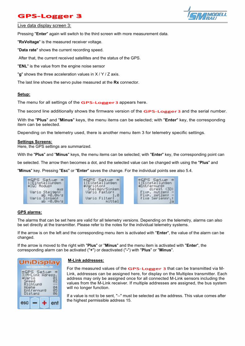
Live data display screen 3:
Pressing "Enter" again will switch to the third screen with more measurement data.
"RxVoltage" is the measured receiver voltage.
"Data rate" shows the current recording speed.
After that, the current received satellites and the status of the GPS.
"ENL" is the value from the engine noise sensor
"g" shows the three acceleration values in X / Y / Z axis.
The last line shows the servo pulse measured at the Rx connector.
Setup:
The menu for all settings of the appears here.
The second line additionally shows the firmware version of the and the serial number.
With the "Plus" and "Minus" keys, the menu items can be selected; with "Enter" key, the corresponding item can be selected.
Depending on the telemetry used, there is another menu item 3 for telemetry specific settings.
Settings Screens: Here, the GPS settings are summarized.
With the "Plus" and "Minus" keys, the menu items can be selected; with "Enter" key, the corresponding point can
be selected. The arrow then becomes a dot, and the selected value can be changed with using the "Plus" and
"Minus" key. Pressing "Esc" or "Enter" saves the change. For the individual points see also 5.4.
GPS alarms:
The alarms that can be set here are valid for all telemetry versions. Depending on the telemetry, alarms can also be set directly at the transmitter. Please refer to the notes for the individual telemetry systems.
If the arrow is on the left and the corresponding menu item is activated with "Enter", the value of the alarm can be changed.
If the arrow is moved to the right with "Plus" or "Minus" and the menu item is activated with "Enter", the corresponding alarm can be activated ("+") or deactivated ("-") with "Plus" or "Minus".
M-Link addresses:
For the measured values of the that can be transmitted via M-Link, addresses can be assigned here, for display on the Multiplex transmitter. Each address may only be assigned once for all connected M-Link sensors including the values from the M-Link receiver. If multiple addresses are assigned, the bus system will no longer function.
If a value is not to be sent, "--" must be selected as the address. This value comes after the highest permissible address 15.

Jeti EX values:
Here, all measured values for transmission to the Jeti transmitter or the JetiBox Profi can be selected individually. Fewer measured values mean faster transmission. Thus, you can hide the values you do not need here.
Spektrum Init:
The Address defines the assignment in the spectrum adapter. Here, it is only important that with several SM telemetry sensors at the spectrum adapter no address be given twice. Normally the default setting is OK.
Thereunder, all Spektrum sensors supported and operated by the can be individually selected or deselected. Each sensor type may
only occur once.
Futaba Init:
Here, the compatibility mode for the Robbe Telemetry Box can be activated.
UniLog Alarms:
The alarms which can be set here concern the operation with Jeti Duplex and directly on the connected UniLog 1 / 2 or UniSens-E. If the arrow is on the left and the corresponding menu item is activated, the value of the alarm can be changed with "Enter". If the arrow is moved to the right with “Plus” or “Minus” and the menu item is activated with “Enter”, the corresponding alarm can be activated (“+”) or deactivated (“-”) with “Plus” or “Minus”.
Page 19

The Online Contest, or OLC for short, is a decentralized contest form which has, for many years, been so popular among man-carrying gliders and paraglider pilots. Here, the flights of the participants are recorded with GPS and then transferred to the OLC system via the Internet. There, each flight is automatically evaluated according to the rules of the online contest and the participant receives points for the flight.
This system has also been accessible to model glider pilots since 2011, so that they can compare their flights in a separate area. Participation is completely free of charge.
The flight task is basically to fly as fast as possible around a triangle that is only predetermined in size (of course in pure gliding flight). More details can be found on the OLC page:
http://rc.onlinecontest.org The special thing about it is the fact that it is flown in a decentralized manner. So, every pilot can do his flights at any place he likes, i.e., when he has time and desire, when the conditions seem to be optimal, etc. All flights can be viewed online, there are daily evaluations and detailed lists of the placements, as well as an annual evaluation at the end of the year.
The can directly generate the IGC file, which is needed for the flight evaluation in the online contest. No conversion of the files is necessary anymore, just transfer the .igc file from the memory card directly into the OLC system and the flight is evaluated.
This file is also signed internally by the , so that the OLC server can check the file for manipulations (this is the highest quality level for a documentation).
The integrated engine noise sensor provides an ENL Value corresponding to the noise level emanating from the drive engine. With motor gliders or models with a retractable engine, climb flights can be very precisely differentiated from pure gliding flights. This is important for the correct evaluation of the flights.
The entries for the pilot name, model type, model name and contest class can also be specified via the GPS converter. These designations are stored on the memory card and transferred to each IGC file. If you use a separate memory card for each model, the correct data can thus always be automatically transferred to the IGC file.
Special features in IGC mode: ■ The IGC file is written to the memory card in addition to the normal NMEA file. ■ The IGC file has a special file name in IGC format. ■ The recording ends automatically as soon as the has detected standstill for 10 seconds.
During these 10 seconds, the green and orange LEDs flash alternately. Auto-stop is therefore always active in IGC mode, even if it has not been switched on separately.
■ As before, the recording start is also possible via various conditions.
Page 20
8. Use in the Online Contest (OLC)
The IGC mode must be activated via the settings.
To obtain optimum readings from the ENL sensor, the should be installed close to the noise source. At the same time, the distance to disturbing noises, e.g., from servos, should be as large as possible. Ideally, the sensor should show a constant maximum value of 999 during climb and fluctuating, low values during glide.
The file shall only be signed and valid for the OLC message if the recording was finished correctly.

8.1. IGC mode "extended
Starting with firmware v1.17, "normal" or "extended" can be selected in IGC mode. "Normal" corresponds to the previous setting and generates the IGC file as described above.
In the "extended" mode, there are the following additional features: ■ The altitude gain value shows the relative altitude compared to the altitude in the starting circle. ■ For the "distance min" alarm for the start circle:
■ the Altitude gain value is set to 0. ■ Altitude and speed are frozen on telemetry for 5 seconds.
■ HoTT Telemetry ■ After the first entry into the start-finish circle (SZK), the relative altitude is carried over instead of the
altitude above the start point. ■ For each entry into the SZK, the relative entry altitude and speed are frozen for 5 seconds. ■ Then the altitude above ground is displayed for 5 seconds.
Page 21

In addition to its functions as a data logger, the is also a full-fledged telemetry sensor for various 2.4 GHz remote control systems. The supports the telemetry of Jeti Duplex (EX), Multiplex M-Link, Graupner HoTT, Robbe/Futaba FASSTest S.BUS2, JR Propo DMSS, FrSky and Spek- trum. Telemetry operation is similar for all usable remote-control systems: live data is displayed on the transmitter or an external display, and with Jeti Duplex and HoTT, can also be operated from the transmitter. If the system has a voice output, then this is also supported by the . The alarm output depends on the telemetry. In some systems the generates the alarm, in others the thresholds are set directly at the transmitter. Please pay attention to the following information.
9.1. Jeti Duplex
The is a full-fledged telemetry sensor for Jeti Duplex 2.4 GHz systems. All measured values can be transmitted live to the ground and displayed on the JetiBox. The Jeti Expander E4, which can connect as much as 4 sensors is also supported.
The connection to the Jeti Duplex receiver is made directly with the supplied patch cable between the "link" connector on the and the "ext." connector on the Jeti Duplex receiver. For the new REX receivers, it must be ensured that the telemetry slot is configured to "JETIBOX/Sensor" or for the central boxes to "Telemetry Input". This setting can be made from the transmitter in the device overview.
9.1.1. EX Telemetry with Jeti Transmitters and JetiBox Profi
The also transmits the data via EX telemetry from Jeti to the transmitters DC/DS- 14/16/24 and to the JetiBox Profi. On the transmitter, the display contents, voice outputs and alarms can be arbitrarily defined from these values. Via the built-in emulation of the JetiBox display, the
can also be operated and set from the transmitter as described below.
The following measured values are displayed in Jeti EX mode. The values can be selected individually via the PC program or the UniDisplay. The Jeti transmitters can receive a maximum of 32 values at the same time. When operating with an expander or to increase the transmission rate, unimportant values can be hidden here.
■ Time Height above sea
level Distance Altitude gain
■ Date Vario Satellite internal temperatures ■ Latitude Flight direction A3 Acceleration X, Y and
Z
■ Longitude ■ Speed ■ Altitude
■ Position ■ Relative
direction ■ Height
■ Rx voltage ■ Air pressure ■ Glide ratio
■ ENL (Noise sensor) ■ Servo pulse
Page 22
9. Telemetry operation
If a GPS-Logger 3 is exchanged for another one, the telemetry values in the DC/DS- 14/16/24 or the Profi Box must be read in again. Each GPS-Logger 3 has its own serial number and the Jeti EX system distinguishes the individual devices with it.
Starting from firmware v1.17, however, the "fixed serial number" option can be switched on. Each GPS-Logger 3 then sends the serial number 12567 and the devices can be interchanged.

9.1.2. Operating the GPS-Logger 3 with the JetiBox.
At the JetiBox, after startup, Tx changes to Rx to Mx for the connected sensors.
Pressing the key switches to the . During initialization, the start screen appears, then the measurement data are displayed.
If a connected UniLog 1 / 2 or UniSens-E was detected during startup, this shall also be reported accordingly in the start screen.
As soon as the first screen with measurement data appears, the and keys can be used to switch through the various data pages. Pressing the key starts recording the data in the
, which is also indicated by an acoustic signal. Pressing the key again stops the recording.
An abbreviation for the currently active data page or the status of the appears alternately at the first position:
first data page, the others follow with B, C, etc..
Recording in progress
Maximum values are displayed
Minimum values are displayed
Pressing the key switches to the settings. Here again, the and keys are used to scroll through the various pages and select the desired item.
The selected value can then be changed by pressing the key again ( and ).
Pressing and at the same time switches the alarm ON or OFF.
Page 23
A simultaneous long press on the and keys switches between the display of the live/ MAX/ MIN values.
Changed settings are saved only when returning to the selection level with .

9.1.3. Display of the measured values on the JetiBox
up: true 3D speed, relative flight direction (0° = away from pilot, 90° = to the right, 180° = back, 270° = to the left)
down: barometric altitude relative to starting point, current rate of climb
up: covered (flight) distance
down: current position of the GPS with respect to the starting point
up: GPS altitude relative to sea level (NN)
down: Measured glide ratio of the last 100m of flight distance.
Behind it, the average speed on these 100m is shown
up: Receiver battery voltage
down: current air pressure
up: elapsed time since the start of recording
down: current date / time
up: latitude of current position
down: Longitude of current position, current direction of movement
up: number of received satellites, GPS status
down: current recording rate, current file number
If a UniLog 1 / 2 or UniSens-E is also connected to the and it is ready, its measured values will also appear here. Values which the UniLog 1 or UniSens-E does not supply, remain simply free or on 0:
up: Drive voltage, barometric altitude with respect to starting point
down: drive current, consumed capacity
up: consumed energy
down: speed, drive power
Page 24

up: receiver battery voltage, barometric altitude relative to starting point
down: Vario, as a numerical value
up: single cells 1 - 3
down: Single cells 4 - 6
up: sensor value at connection A1
down: sensor value at connection A2
up: sensor value at connection A3
down: servo pulse from receiver at Rx connector, servo pulse for controller at ESC connector
up: actual air pressure
down: UniLog 1 / 2 internal temperature
9.1.4. Alarm
When using the Jeti transmitter modules and displaying the data via the simple JetiBox, all alarms, as well as the vario tones are generated directly by the . All settings need to be made on the
.
The JetiBox Profi and the Jeti transmitters can generate alarms and vario tones themselves in the Jeti EX mode. These are then preset in the box or transmitter. Alarms that are set in the are additionally produced.
Page 25

9.2. Multiplex M-Link
The is also a full-fledged telemetry sensor for Multiplex M-Link 2.4 GHz systems. The GPS readings can be transmitted live to the ground and displayed directly on the Multiplex RoyalPro or COCKPIT SX transmitter.
The connection to the M-Link receiver is made directly via the supplied patch cable as described in point 6.3.
On the ground, the data is displayed directly on the Multiplex RoyalPro or COCKPIT SX transmitter.
The settings for the telemetry are made either with the UniDisplay (see also chapter 7) or with our "SM GPS converter" software on the PC. The addresses for the display on the Multiplex remote control (line in which the respective value is displayed), can be freely selected here.
9.2.1. Off-landing mode with M-Link With M-Link, after 2 minutes without movement of the , latitude and longitude are displayed on the addresses of the Vario values and Speed in 5-second intervals. The display alternates between the value before the decimal point with the unit “mAh” and the value after the decimal point with the unit “ml”. More meaningful units - like degrees and minutes - are unfortunately not allowed by M-Link. The values must be completed with leading zeros to 4 digits, so "4912 mAh" "268 ml" becomes "4912" "0268" and in the correct notation 49° 12.0268'.
9.2.2. Alarms All alarms are generated directly in the M-Link by the . All settings need to be done on the .
Page 26

Later, the values can be evaluated directly at each individual waypoint of the 3D display in Google EarthTM. Furthermore, the curve in Google EarthTM can be colored according to a selected M-Link value.
Figure 1: Aerial circuit with looping. Full M-Link configuration with GPS, UniLog and temperature sensor.
Page 27
As an additional function, the constantly writes all data on the Multiplex M-Link bus system and stores them on the memory card parallel to its own data. This allows you to expand your M-Link sensor system with a practically unlimited data logger!

9.3. Graupner HoTT The is also a full-fledge telemetry sensor for the Graupner HoTT 2.4 GHz system. The measured values can be transmitted live to the ground and displayed directly either on the Smart-Box at the HoTT transmitter or on the display of the HoTT transmitter. The connection to the HoTT receiver is made via the supplied patch cable between the slot on the
and "T" on the HoTT receiver.
9.3.1. Alarms
The supports the text mode of the HoTT system as well as the digital mode. In both modes all adjustable alarms of the are indicated via the transmitter through beeping or the voice output.
9.3.2. Vario The HoTT transmitters fade out the range from -0.5 m/s to 0 m/s in the sound output. To still get a continuous Vario tone, the skips this range. For a more sensitive response of the acoustic output, a "Vario factor" of 2 to 4 should be set in the
at HoTT. The result is a good resolving acoustic output without a hole around the zero point. Though you need to accept that the Vario value displayed and recorded in the transmitter does not correspond to reality.
9.3.3. Text mode
You get to the text mode via the telemetry menu and "Set, Display". With the left transmitter’s keypad, you can now call up the "GPS" for the using the keys "up" and "down". Clicking to the right now takes you from the receiver data to the text display of the .
The operation is done with the transmitter’s right touchpad. Structure and content are completely identical to the screens of the UniDisplay, see also chapter 7.
All alarms can also be set here, which are then indicated by the transmitter through beeping or the voice output.
The operation seems to be a bit sluggish in the text mode because the data cannot be updated so often via the telemetry.
Page 28

9.3.4. Digital mode The sends the data in the "GPS" module format, so that the transmitter can display the values on the corresponding screens. From the transmitter’s standard display, the "left" and "right" keys of the left touchpad call up the digital mode. With the keys "up" and "down", the "GPS" can now be called up to display the data of the . With the "left" and "right" keys of the left touchpad you can switch between the individual screens of the .
Some values are assigned differently by the
:
■ Vario in m/3s: shows the "Altitude gain" value; the difference in altitude in the last 10 seconds.
■ Longitude and latitude: Are displayed inversely when the
is recording on the memory card.
Page 29

9.4. Futaba S.BUS2
Also, with the Robbe/Futaba telemetry, FASSTest, the can be used as S.BUS2 sensor. The is connected to the S.BUS2 slot of the receiver like any other sensor.
Currently the GPS-Logger 3 is not yet registered in the transmitters, therefore it uses already existing sensor protocols. The integration was tested with the T14SG firmware v1.4 and the T18MZ firmware v2.3.1 on the receivers R7008SB and R7003SB. Older firmware versions may not fully support the integration.
9.4.1. Registration at the transmitter
In order to use the with the S.BUS2, it must first be registered at the transmitter, like all S.BUS2 sensors. To do this, connect the "Link" connector of the to the "S.I/F" connector on the transmitter. Some transmitters like the T14SG do not provide a power supply at this socket, then the must be supplied with a separate battery via a Y-cable. The
behaves like a Robbe/Futaba sensor and is integrated into the system in the exact same way. Please also refer to the transmitter's instructions.
However, the currently occupies six Robbe/Futaba sensor values to be able to display all measured values. Some measured values cannot be displayed with the correct unit, here you must remember the assignment with the T14SG. With the T18MZ you can rename the sensors to make the assignment more understandable.
9.4.2. Robbe Telemetry Box
The Robbe Telemetry Box as another possibility of displaying the telemetry data at Futaba, unfortunately does not know the temperature sensor, SBS-01T, used by the . Therefore, there is the "Telemetry Box" option in the settings, which replaces all Futaba SBS-01T sensors with the TEMP125 sensor, when logging in. This allows the to be used with the Telemetry Box without any major restrictions.
Page 30
With S.BUS2, servo data and sensor values can be connected on the same data line. However, since the servo data are much more important than the sensor values, we strongly recommend a strict separation. All servos are connected to the S.BUS1 port of the receiver, all sensors to the S.- BUS2. This way, a sensor can never interfere with the data for the servos, even in the event of a fault. If the GPS-Logger 3 should nevertheless be operated together with the servos at the S.BUS2, a connection cable, order no. 9110, between GPS-Logger 3 and S.BUS2 is mandatory! This also decouples the sensor from the bus to such an extent that an influence on the servo data is impossible.
From firmware v1.17 onward, the sends the reception quality output by the receiver on the S.BUS2 back to the transmitter as an additional temperature sensor TEMP125. Thus, this value can also be used for corresponding alarms in the transmitter. Output are %-values in the steps 25/50/75/100.
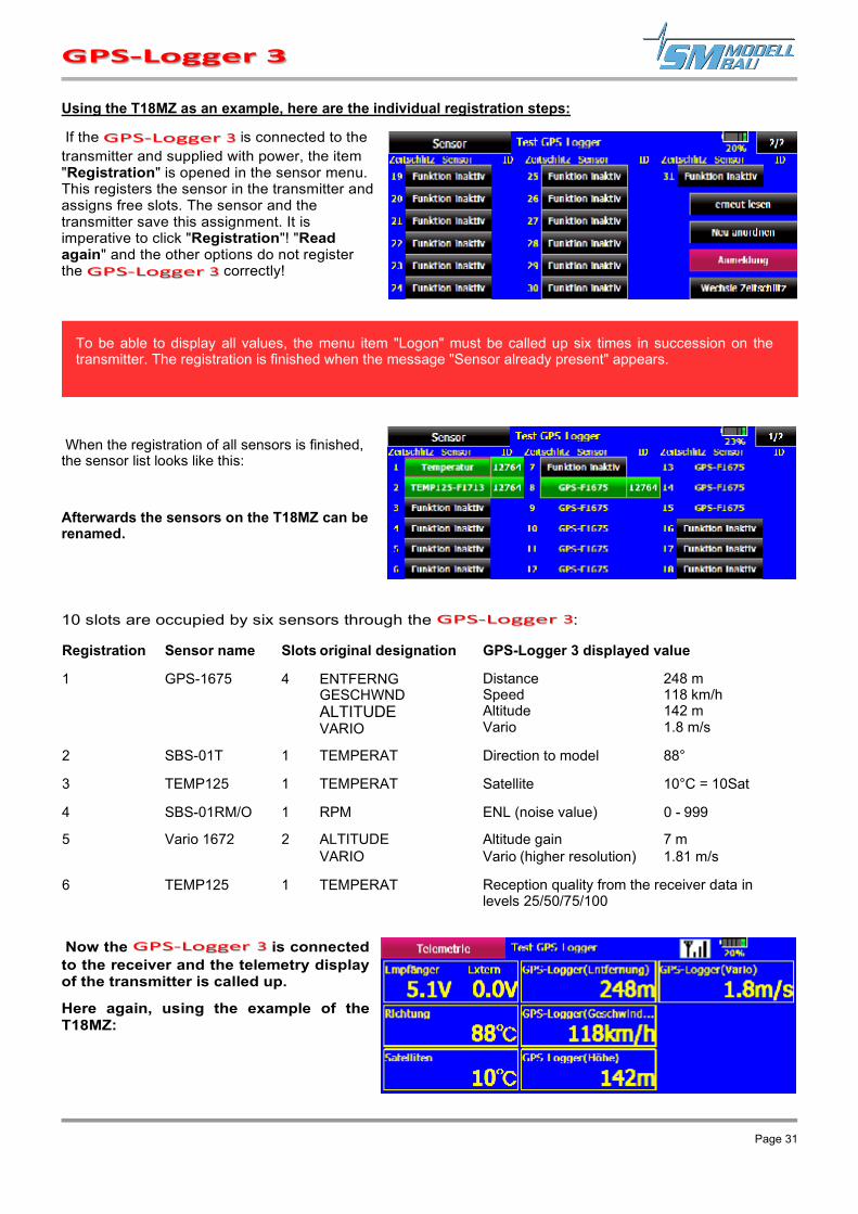
Using the T18MZ as an example, here are the individual registration steps:
If the is connected to the transmitter and supplied with power, the item "Registration" is opened in the sensor menu. This registers the sensor in the transmitter and assigns free slots. The sensor and the transmitter save this assignment. It is imperative to click "Registration"! "Read again" and the other options do not register the correctly!
When the registration of all sensors is finished, the sensor list looks like this:
Afterwards the sensors on the T18MZ can be renamed.
10 slots are occupied by six sensors through the :
Registration Sensor name Slots original designation GPS-Logger 3 displayed value
1 GPS-1675 4 ENTFERNG GESCHWND ALTITUDE VARIO
Distance 248 m Speed 118 km/h Altitude 142 m Vario 1.8 m/s
2 SBS-01T 1 TEMPERAT Direction to model 88°
3 TEMP125 1 TEMPERAT Satellite 10°C = 10Sat
4 SBS-01RM/O 1 RPM ENL (noise value) 0 - 999
5 Vario 1672 2 ALTITUDE Altitude gain 7 m VARIO Vario (higher resolution) 1.81 m/s
6 TEMP125 1 TEMPERAT Reception quality from the receiver data in levels 25/50/75/100
Now the is connected to the receiver and the telemetry display of the transmitter is called up.
Here again, using the example of the T18MZ:
Page 31
To be able to display all values, the menu item "Logon" must be called up six times in succession on the transmitter. The registration is finished when the message "Sensor already present" appears.

The same values look like this for the T14SG (the designations cannot be changed here):
9.4.3. Alarms
In principle, with the S.BUS2 the alarms are defined in the transmitter. The has no possibility to trigger an alarm directly at the transmitter.
Page 32

9.5. JR Propo DMSS
The can also be used with the JR Propo DMSS telemetry. Currently, the JR telemetry does not know GPS yet, therefore only the transmission of altitude, Vario and speed is currently possible. GPS coordinates will be added later.
The is connected to the receiver’s sensor slot like any other sensor and transmits the following data:
■ Air pressure, altitude, vario (sensor address 0x03 "Pressure / Altitude")
■ Speed (sensor address 0x05 "Air Velocity")
No other sensors occupying the same addresses can be connected. For the free addresses, additional sensors can simply be plugged into the receiver with a V-cable parallel to the .
The connection with the XG8 transmitter, firmware version 0001-0012 and the RG831B receiver was tested.
9.5.1. Display on the transmitter
All values can be displayed directly, the sequence on the display is freely selectable.
9.5.2. Alarms
In principle, with JR DMSS, the alarms are defined in the transmitter. The has no possibility to trigger an alarm directly at the transmitter. All alarm thresholds, as well as Vario tone generation are therefore defined in the transmitter.
Page 33

9.6. FrSky
For FrSky telemetry, all receivers with the new "S.Port" connector are supported. The receiver must be bound for telemetry operation in D16 mode!
The is connected to the sensor slot of the receiver like any other sensor and transmits the following data:
Altitude
GPS Altitude (NN)
„Alt“
„GAlt“
Vario „VSpd“
Acceleration „AccX“ „AccY“ „AccZ“
GPS Coordinates „GPS“
Speed „GSpd“
Direction to model „Hdg“
GPS Time „Date“
Distance Address 0x0860 in meters
Satellites Address 0x0870
Altitude gain Address 0x0880 in Meter
Flight direction Address 0x0890 in Degree
Relative direction Address 0x08A0 in Degree
The sensor address (ID) of the in the FrSky system can be freely selected in the settings. No other sensors occupying the same addresses can be connected. For the free addresses additional sensors are simply plugged in with a V-cable parallel to the at the receiver.
9.6.1. Display at the transmitter
All values can be displayed directly, the sequence on the display is freely selectable.
Here the sensors with free address have already been given meaningful names, e.g., the sensor 0x0860 as Del.
9.6.2. Alarms
In principle the alarms of the Taranis are defined in the transmitter. The has no possibility to trigger an alarm directly at the transmitter. All alarm thresholds, as well as Vario tone generation are therefore defined in the transmitter.
Page 34
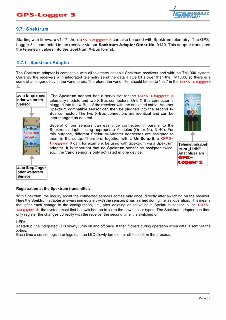
9.7. Spektrum
Starting with firmware v1.17, the can also be used with Spektrum telemetry. The GPS-Logger 3 is connected to the receiver via our Spektrum-Adapter Order-No. 9120. This adapter translates the telemetry values into the Spektrum X-Bus format.
9.7.1. Spektrum-Adapter
The Spektrum adapter is compatible with all telemetry capable Spektrum receivers and with the TM1000 system. Currently the receivers with integrated telemetry send the data a little bit slower than the TM1000, so there is a somewhat longer delay in the vario tones. Therefore, the vario filter should be set to "fast" in the
.
The Spektrum adapter has a servo slot for the telemetry module and two X-Bus connectors. One X-Bus connector is plugged into the X-Bus of the receiver with the enclosed cable. Another Spektrum compatible sensor can then be plugged into the second X-Bus connector. The two X-Bus connectors are identical and can be interchanged as desired.
Several of our sensors can easily be connected in parallel to the Spektrum adapter using appropriate Y-cables (Order No. 3140). For this purpose, different Spektrum-Adapter addresses are assigned to them in the setup. Therefore, together with a UniSens-E, a
can, for example, be used with Spektrum via a Spektrum adapter. It is important that no Spektrum sensor be assigned twice, e.g., the Vario sensor is only activated in one device.
Registration at the Spektrum transmitter:
With Spektrum, the inquiry about the connected sensors comes only once, directly after switching on the receiver. Here the Spektrum adapter answers immediately with the sensors it has learned during the last operation. This means that after each change in the configuration, i.e., after deleting or activating a Spektrum sensor in the
, the system must first be switched on to learn the new sensor types. The Spektrum adapter can then only register the changes correctly with the receiver the second time it is switched on.
LED: At startup, the integrated LED slowly turns on and off once. It then flickers during operation when data is sent via the X-bus. Each time a sensor logs in or logs out, the LED slowly turns on or off to confirm the process.
Page 35

9.7.2. Display on the transmitter
The can display a total of four different spectrum sensor types. All of them can be individually deactivated to avoid double assignments on the X-Bus. The data can be processed in the transmitter in the exact same way as with the original Spektrum sensors, i.e., voice output, display, alarms, and saving are possible.
GPS Sensor („GPS“)
● Speed ● Altitude ● Model Flight direction (heading) ● Distance and direction to the model (the
transmitter calculates these values from the difference to the first coordinates).
● Longitude and latitude ● GPS time ● Number of satellites
Vario Sensor („Vario“) ● Altitude ● Vario
Acceleration sensor ("GForce") ● Acceleration X, Y, Z ● Minimum and maximum values
USER16 Sensor („USER 16SU“)
A sensor with free fields that are assigned as follows:
● sField1: Distance to the model in meters. ● sField2: Direction to the model in degrees ● sField3: altitude gain in meters ● uField1: Flight distance in meters ● uField2: Glide ratio ● uField3: Speed at glide ratio in km/h ● uField4: ENL value (noise sensor)
9.7.3. Alarms
In principle, with Spektrum, the alarms are defined in the transmitter. The GPS-Logger 3 has no possibility of triggering an alarm directly at the transmitter. All alarm thresholds, as well as Vario tone generations are therefore defined in the transmitter.
Page 36

9.8. PowerBox Core P2Bus
From firmware v1.24, the GPS-Logger 3 can also be used with PowerBox Core telemetry. Currently the GPS-Logger 3 supports the full transmission of all telemetry values and the switching between German/English and meters/feet for the units. A setting menu of the GPS-Logger 3 is not yet built in.
9.8.1. Display on the transmitter
Blank start screen A long press on the free area brings up the window selection.
After clicking on the desired window, "Telemetry" ... ... can be used to create a widget. The + opens the sensor list.
Now, the desired value can be selected. In this widget, several values can also be alternately
displayed, simply insert with +.
Page 37

A fully occupied telemetry page … ...................................... ... it continues on page 2.
Alarms are defined directly in this widget in the transmitter.
English designations and units after the changeover in the system. The sensors must be re-scanned in a sensor widget to switch.
9.8.2. Alarms
A long click on the sensor in the widget also shows the sensor’s address. This can also be changed with X→Y to be able to connect several identical sensors.
In principle, with PowerBox, the alarms are defined in the transmitter. The GPS-Logger 3 has no possibility of triggering an alarm directly at the transmitter. All alarm thresholds, as well as Vario tone generations are therefore defined in the transmitter.
Page 38

10. Operation with UniLog 1 / 2 or UniSens-E
With the connection cables order no. 2720 or 2721 the can be connected directly with the UniLog 1 / 2 or the UniSens-E.
This results in the following possibilities:
■ Recording of all measured values from the UniLog 1 / 2 or UniSens-E on the memory card of the GPS-Logger 3 in synchrony with the other data.
■ Display of the measured values from the UniLog 1 / 2 or UniSens-E via Jeti Duplex telemetry on the ground.
■ Monitoring of adjustable limit values via the Jeti Duplex telemetry
■ Practically unlimited memory expansion for the UniLog 1
■ Evaluation of UniLog 1 / 2 or UniSens-E data in Google EarthTM at any waypoint.
Figure 2: Kuban Eight with UniLog data
Page 39
To display the taken battery capacity from UniLog 1, the connection A2 must be set to "capacity mAh" in the setup!
The connection to UniLog 1 / 2 or UniSens-E works only with HoTT, Jeti and M-Link operation. The COM interface cannot be used with the other telemetries.

On our homepage, in the Software & Updates section, you will find the free software "SM GPS Converter". With this software the measurement data can be read in and converted directly into the .kmz format for Google EarthTM. During the conversion there are different possibilities of highlighting or colorizing certain values in the later 3D view.
11.1. Convert files
The software opens with the "Convert" tab. Here a file from the GPS-Logger 3 can be selected and converted with adjustable options into the Google EarthTM format ".kmz" or into a table file ".csv" for Excel or OpenOffice. If desired, the generated file can also be displayed directly in Google EarthTM.
Page 40
11. the SM GPS converter software
If you move the mouse pointer over the buttons, you will see short help texts for operation.

11.2. Minimum and maximum values
After a file has been converted, all extreme values of this file can be viewed clearly in the Maxima window.
Page 41
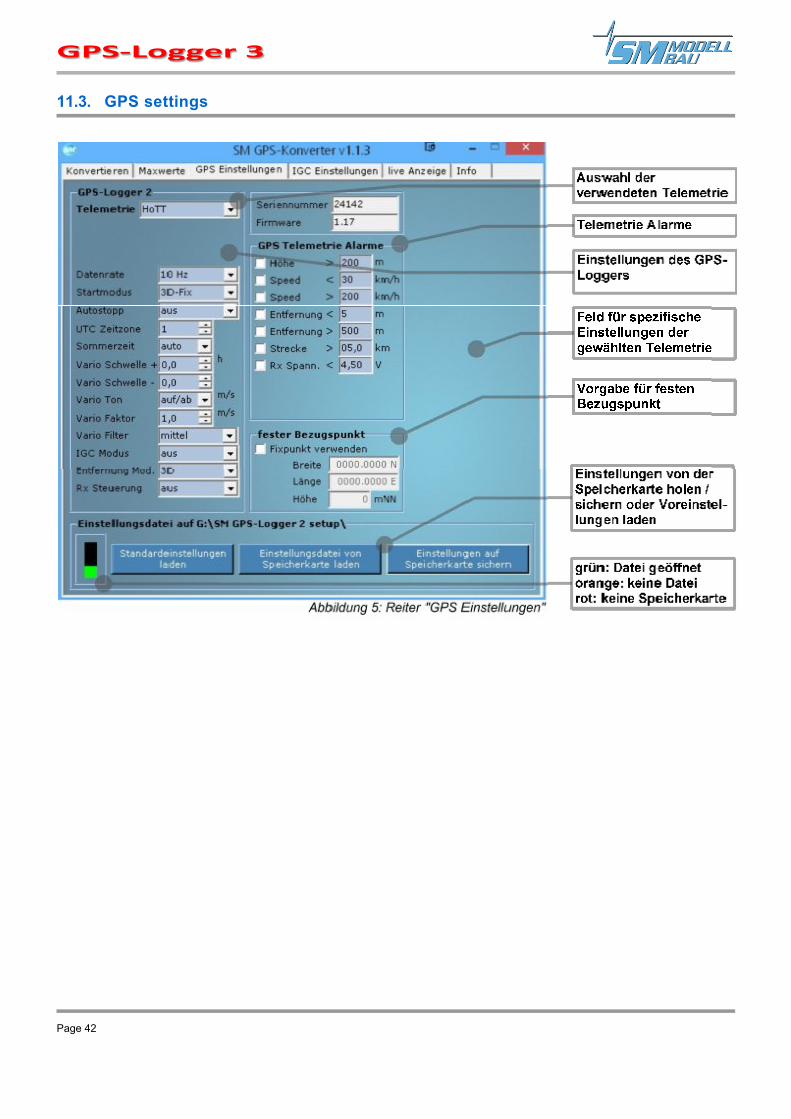
11.3. GPS settings
Page 42

11.4. IGC Settings
Here you can define default settings for the IGC mode. These texts are taken over by the GPS-Logger 3 into the IGC file.
When evaluating the data in the OnlineContest, suitable fields can be automatically filled.
11.5. Live access to the GPS-Logger 3
If the GPS-Logger 3 is connected to the PC with the USB-Interface, it is possible to access the GPS-Logger 3 directly via the terminal function of our software. The display is identical with the live operation of the UniDisplay. See also point Error: Reference not found.
Page 43
The must be supplied with external power for connection to the PC! For example, directly with a 4-cell receiver battery.

11.6. Info / Settings of the SM GPS-Converter
The "Info" tab contains program information and settings for Google EarthTM and for the automatic online update. The SM GPS-Converter searches on our homepage for new versions of the program and the firmware of the GPS-Logger 3 and can install them immediately.
Page 44

12. Firmware update of the GPS-Logger 3
A new firmware for the is simply installed via the micro-SD memory card. A corresponding file with the update can be downloaded for free on our home page at www.sm-modellbau.de in the menu item, Software & Updates.
For example, the file has the following file name for v1.00: GL2v100.UPD.
Procedure: ■ The file is copied to the folder "SM GPS-Logger 2 update" on the memory card. If the folder does not exist, it must
be created with exactly this name.
■ At the next start of the , the red LED flashes during the update process.
■ The then starts with the new firmware.
■ The file may remain on the memory card; it will only be loaded once.
Page 45
When the PC software "SM GPS Converter" is started, the program automatically searches for a newer firmware on our server. If a newer file is found, it can be automatically downloaded to the memory card if desired. This keeps the always up to date.
The file name of the firmware update and the name of the folder for the update must not be changed!

13. Version history
Here you can find all firmware versions and the changes to the previous version. You can read out the version of your firmware with our software "SM GPS Converter" or the UniDisplay.
Version Date
Comment
1.17 02.2017 1. Spektrum telemetry built-in via Spektrum adapter: - up to 4 sensors: GPS Sensor, Vario Sensor, G Sensor, USER16
2. M-Link: Rx voltage on own address 3. Futaba:
- compatibility mode for Robbe telemetry box - the signal quality output by the receiver (25/50/75/100) is read in and transmitted on an
additional sensor slot as TEMP125 4. FrSky: neue Werte werden mit eigenen IDs übertragen
- Distance 0x0860 in meters - Satellites 0x0870 - Altitude gain 0x0880 in meters - Flight direction 0x0890 in degrees - Relative direction 0x08A0 in degrees
5. Optimized and accelerated calculation of vario data: - Vario values are now less smoothed, but are more updated - Faster transfer of vario values, especially with Jeti and HoTT - New option "Vario Filter": "slow" being somewhat like the previous evaluation, "medium"
and "fast" are correspondingly faster - Altitude display is faster
6. Soft zeroing of altitude added when model is on the ground 7. new option "fixed serial number" sends serial number 12567 via telemetry at Jeti and
Futaba 8. set start point via "Rx control" is now done when changing from +100% to -100% servo
travel, previously the other way round 9. fixed point (home) can be stored via the GPS converter or the UniDisplay: the alarm for maximum distance and the value distance are then calculated to this fix point (either 2D or 3D) the alarm for minimum distance and the direction continue to refer to the start point
10. new start mode: "Rx Signal 11. new alarm for minimum speed 12. new IGC mode "extended”
1.18 03.2017 1. unwanted restarts eliminated 1.19 06.2017 1. abortions especially at GPS logger 1 eliminated
2. HoTT: Alarm 'E' no longer generates "pling-pling" on the mc-28 but "weak telemetry channel". Alarms without corresponding voice output are omitted without replacement: COM connected and disconnected; start and stop saving, track
3. Futaba: at the display of the signal quality the values 50% and 75% were interchanged 4. IGC mode extended: Zero the altitude difference when setting the start point via the Rx
channel 1.20 02.2019 1. introduction of the GPS-Logger 3
2. Futaba: with the Vario 1672 sensor, the altitude gain is now transmitted instead of just the altitude.
3. FrSky: coordinates and vario are transmitted with high priority 1.21 03.2019 1. Jeti: assignment of the single values did not fit to the GPS converter
Page 46

Version Date Remark
2. Vario would no longer be updated if a UniSens-E/UniLog 2 was connected 1.22 03.2019 1. GPS-logger 3: speeds over 185 km/h caused an error
2. Calculation of glide ratio no longer worked 3. OLC: Filter for manual setting of the starting point via the receiver channel, so that short
disturbances do not shift the start point 4. OLC: barometric altitude was missing in the igc file
1.23 04.2019 1. GPS-logger 1: fix for wrong dates due to "week roll over" in the GPS signal on 04/06/2019
1.24 08.2019 1. PowerBox Core (P2BUS) support built in: - Only possible with GPS-logger 2/3, GPS-Logger 1 has too little memory. - Currently only display of measured values, assignment of address and switching between
German/English, and Metric/Feet, no menu - default address: 188
2. GPS-Logger 1: Another fix for wrong dates due to "week roll over" in GPS signal 3. Alarm for maximum distance will be cleared automatically after 5 seconds until next
exceedance
1.25 06.2020 1. jeti: altitude and altitude gain are displayed from 10 m on without decimal point 2. PowerBox: Accelerometers added to the values 3. FrSky: Variovalue is additionally transmitted with ID 0x08b0 with high resolution at GPS-
Logger 2/3 4. soft zeroing of altitude can now be switched off
Page 47


