Paper ID: 59, Page 1 3 rd International Seminar on ORC Power Systems, October 12-14, 2015, Brussels, Belgium SMALL SCALE SOLID BIOMASS FUELLED ORC PLANTS FOR COMBINED HEAT AND POWER Stefano Ganassin, Jos P. van Buijtenen* Tri-O-Gen B.V., PO Box 25, 7470 AA Goor, The Netherlands E-mail: [email protected]* Corresponding Author ABSTRACT A high efficiency Organic Rankine Cycle (ORC) power unit of 170 kWe has been developed in The Netherlands. The ORC system is based on a thermally stable hydro-carbon as a working fluid, hence suitable for direct use of intermediate temperature heat sources. The unit is capable of transforming heat flows at temperatures between 350 and 530 ºC into electricity. Typical applications involve the exhaust gasses of gas- or diesel engines and small gas turbines. Further applications include solid biomass combustion, incinerators, industrial residual heat and industrial flares. This paper describes the application of biomass fuelled cogeneration (CHP) units, as in operation and on order now. Wood or biomass is gaining interest as energy source for small district heating networks, while it is already widely used when available as a by-product, e.g. in sawmills. During combustion, temperatures reached are way above the level needed for the heating purpose. Hence, there is a considerable amount of exergy available, which can be used to generate electricity. By applying an Organic Rankine Cycle (ORC) system, flue gasses from the wood combustor deliver their high temperature heat to be converted into electricity, leaving lower temperature heat to be supplied to the district heating grid, or to be used for local heating and drying. This can be materialized in various ratios between power and heat, thus following the varying heat demand while maintaining total system efficiency. An innovative system was developed, where the ORC is directly connected to the flue gas flow, without the need of an intermediate system. The system set-up, flue gas cleaning and evaporator cleaning methods are described in this paper, together with operational experience gained so far in several units. 1. INTRODUCTION In recent years, the urge for utilizing all forms of available energy has increased significantly. One of these sources is heat, as can be generated by the combustion of wood and other residuals. The best way to utilize this energy is to convert it into electricity using a so-called Organic Rankine Cycle (ORC), while low temperature heat remains available for heating and drying purposes. The development started in the early nineties at the Lappeenranta University of Technology in Finland, and was industrialized and commercialized by a Dutch company since 2002. Deployment took place since 2006, resulting in 30 units build so far, and 6 units on order or being commissioned. Most units so far utilize the residual heat from Internal Combustion Engines (ICE) exhausts, but already five units employ the heat generated by the combustion of biomass. This paper will highlight the ORC system as well as the specific technology used for the application of high temperature dust loaded flue gas as a heat source.
Transcript
Paper ID: 59, Page 1
3rd International Seminar on ORC Power Systems, October 12-14, 2015, Brussels, Belgium
A high efficiency Organic Rankine Cycle (ORC) power unit of 170 kWe has been developed in The
Netherlands. The ORC system is based on a thermally stable hydro-carbon as a working fluid, hence
suitable for direct use of intermediate temperature heat sources. The unit is capable of transforming heat
flows at temperatures between 350 and 530 ºC into electricity. Typical applications involve the exhaust
gasses of gas- or diesel engines and small gas turbines. Further applications include solid biomass
combustion, incinerators, industrial residual heat and industrial flares.
This paper describes the application of biomass fuelled cogeneration (CHP) units, as in operation and
on order now.
Wood or biomass is gaining interest as energy source for small district heating networks, while it is
already widely used when available as a by-product, e.g. in sawmills. During combustion, temperatures
reached are way above the level needed for the heating purpose. Hence, there is a considerable amount
of exergy available, which can be used to generate electricity.
By applying an Organic Rankine Cycle (ORC) system, flue gasses from the wood combustor deliver
their high temperature heat to be converted into electricity, leaving lower temperature heat to be
supplied to the district heating grid, or to be used for local heating and drying.
This can be materialized in various ratios between power and heat, thus following the varying heat
demand while maintaining total system efficiency.
An innovative system was developed, where the ORC is directly connected to the flue gas flow, without
the need of an intermediate system. The system set-up, flue gas cleaning and evaporator cleaning
methods are described in this paper, together with operational experience gained so far in several units.
1. INTRODUCTION
In recent years, the urge for utilizing all forms of available energy has increased significantly. One of
these sources is heat, as can be generated by the combustion of wood and other residuals. The best way
to utilize this energy is to convert it into electricity using a so-called Organic Rankine Cycle (ORC),
while low temperature heat remains available for heating and drying purposes.
The development started in the early nineties at the Lappeenranta University of Technology in Finland,
and was industrialized and commercialized by a Dutch company since 2002. Deployment took place
since 2006, resulting in 30 units build so far, and 6 units on order or being commissioned. Most units
so far utilize the residual heat from Internal Combustion Engines (ICE) exhausts, but already five units
employ the heat generated by the combustion of biomass. This paper will highlight the ORC system as
well as the specific technology used for the application of high temperature dust loaded flue gas as a
heat source.
Paper ID: 59, Page 2
3rd International Seminar on ORC Power Systems, October 12-14, 2015, Brussels, Belgium
2. DESIGN OF THE ORC
Figure 1 shows the cycle scheme and the process of the Organic Rankine Cycle in the T-s diagram.
Liquid working fluid is pumped from the storage vessel to the main pump, which is mounted on the
same shaft as the turbine and the high-speed generator. The working fluid is compressed to its maximum
working pressure and then enters the recuperator and subsequently the evaporator. Residual or waste
heat is led through the evaporator, where the working fluid is heated up to the boiling point, evaporated
and superheated. Then expansion takes place in the turbine, which drives the high speed generator and
the main pump. After expansion, the sensible heat in the fluid is re-used in the recuperator, to preheat
the liquid before it enters the evaporator. Below the recuperator the condenser is situated, where the
vapor is condensed using a liquid coolant, before it flows back into the storage vessel.
Figure 1: Cycle scheme and T-s diagram
This cycle uses toluene as working fluid. This allows a high value (320 °C) of the turbine inlet
temperature thanks to its thermal stability. Moreover, the working fluid is used for lubrication and
cooling of the turbo-generator which also embodies the main feed pump (van Buijtenen et al, 2003).
This combination of turbine, generator and pump is running at high speed (25.000 rpm) without the
need for a gearbox. This allows for a completely hermetic design, without the necessity of shaft seals.
The turbine is a single stage radial inflow machine, driving an a-synchronous solid rotor induction type
generator and the main radial pump. Speed is optimized for high turbine and pump efficiency.
The recuperator and the condenser are plate and shell type heat exchangers.
The evaporator is of simple smooth pipe design, constructed out of horizontal U-shaped piping fixed at
one side for free expansion. The small diameter pipes are made of stainless steel, and there is adequate
access for cleaning. Allowable material temperature is well above the heat source temperature, so the
evaporator is sufficiently safeguarded against no-flow conditions. The standard design can be sized to
the specific conditions of the applications, as heat source temperature and flow.
Flue gasses are guided in a vertical direction from top to bottom through the evaporator. The lowest
temperature is reached at the lowest point, where provisions are made to collect possible condensate
during start and stop. The working fluid passes the series of pipes in a vertical direction from bottom to
top, in once-through mode. There is no need for a drum, and the outflow conditions are controlled such
that no liquid can be present while entering the turbine.
Paper ID: 59, Page 3
3rd International Seminar on ORC Power Systems, October 12-14, 2015, Brussels, Belgium
3. BIOMASS COMBUSTION AND ORC
3.1 Biomass combustion
There are several techniques to combust different kinds of biomass. Techniques are divided into grate
firing and fluidized bed. To abate NOx emission, there can be a certain amount of flue gas recirculation,
affecting the resulting flue gas temperature, which typically ranges from 900 to 1100 °C. The term solid
biomass refers to a large variety of organic substances, which ranges from clean, new wood from the
wood production industry like sawmills, to demolition wood, and residues from wood harvesting and
other agricultural processes like rice harvesting, sugar cane, olive plants et cetera.
These latter materials generally have no other application, and are considered as waste to get rid of
through combustion. The resulting CO2 emission would have been created anyway, but is using short
cyclic carbon which is absorbed again in new crops. With this CO2 neutral process useable electrical
and thermal energy is produced in CHP mode replacing fossil energy. Although the burner has to be
adapted to the kind of biomass, the ORC will remain similar in all cases, as the flue gas has to be cooled
to 530 °C anyway. In order to reach the nominal power output, the amount of biomass to be burned
might have to be adapted depending on calorific value and moist content.
3.2 Application to ORC
The heat energy generated from the combustion of biomass is generally used for heating and drying
purposes. The required temperatures (50 to 100 °C) for heating and drying are well below the
temperature generated by the biomass combustion. This means that a considerable amount of the
available exergy (the measure for recoverable work from a flow of heat at a certain temperature) can be
converted into electricity, generally considered as the higher valued form of useable energy, leaving the
majority of the heat available for heating and drying. The available temperature trajectory is roughly
from 1000 °C (flue gas) to the temperature needed for heating: typically 100 °C and below. However,
due to the character of the flue gas that carries the energy (pressure and dust loading), this flue gas
cannot directly be used for the generation of power as in a gas turbine. Another process has to take care
of this, either in an open air cycle (indirectly fired gas turbine) or in a closed cycle using water (steam
turbine) or using an appropriate organic fluid (Organic Rankine Cycle).
While normally ORC technology is considered to be suitable for low temperature heat sources, here the
temperature is high, but the scale of the plant calls for something else then steam. One must realize, that
even in large steam plants, live steam temperature will not exceed 540 - 600 °C, so the source
temperature is reduced anyway. Moreover, this temperature will demand for a very high steam pressure
and subsequently very low steam volume flow, not favorable for small plants. Organic fluids however,
have a critical pressure at a much lower pressure than steam, so evaporation can still take place close to
this critical point, hence reducing the heat exchange area for evaporation. Moreover, due to the positive
slope of the right hand side boundary of the co-existence area, only a limited amount of superheating is
necessary for completely dry expansion down to condenser pressure. Apart from these thermodynamic
considerations, there are a number of arguments for applying ORC technology for small plants:
• During expansion, organic fluids will show a high volume flow at low enthalpy drop. This leads to
the possibility of designing single stage turbines. Using water/steam, at a pressure over 60 bar
(necessary to get sufficient thermodynamic cycle efficiency) one should at least use 3 to 4 stages.
This would require axial turbine stages and eliminates the possibility to use radial turbine designs,
which are known for being very suitable for small sizes (compare e.g. turbo-chargers for
reciprocating engines).
• For small power plant (<500 kWe) steam cycles are often operated at even lower pressures (<20bar)
and screw expanders are used instead of turbines. This solution however only achieves low
efficiencies.
• Most organic fluids have good lubrication properties, so it can be used to lubricate bearings,
eliminating the need for separating a conventional lubricant from the working fluid.
Paper ID: 59, Page 4
3rd International Seminar on ORC Power Systems, October 12-14, 2015, Brussels, Belgium
• Most organic fluids show a very low electric conductivity (practically 0), so electrical components
might be subjected to it. This means that the generator can be cooled by operating in an environment
of working fluid vapour.
• The use of organic fluids necessitates designing the system completely hermetic. As this can be
done successfully based on the above elements, this leads to the advantage that units can be operated
un-manned and/or remotely controlled and supervised automatically.
• In several countries, steam plants are required to be supervised by a qualified operator, adding to
the operational costs of the plant.
Another characteristic of the biomass under consideration is its local availability, next to the local
demand for heating and drying. This calls for relatively small plants, where gas turbine and steam cycle
technology can perform only at rather low efficiencies. The logical choice then will be the Organic
Rankine Cycle. Several solid biomass fueled ORC power plants in the range between 1 and 5 MWe
have been installed in the last 10 years. These plants demand a heat input between 5 and 25 MWth,
meaning that the feedstock must be collected in a large radius and transported to the power plant. The
same counts for the heat distribution network, which must be extensive in order to allow complete
absorption of the available heat. To avoid the heat losses of an extensive heat network and to avoid the
cost and CO2 production of feedstock transportation, the general tendency is to reduce the size of plants
even further, to the range of 100 to 300 kWe. Moreover, the general tendency to more decentralized
power generation is facilitated by the development of smart grid technology.
3.3 Direct Evaporation with flue gas from biomass combustion Several ORC power plants are operated since several years powered by a solid biomass burner. When
using flue gas from the combustion of biomass in an ORC evaporator, one has to take care of two facts,
one being the high temperature of 900 to 1100 °C, and the other being the dust loading of such gases.
As many working fluids of ORC systems are selected for the use of low temperature heat, chemical
stability is not one of the criteria. So if such systems are to be used for high temperature flue gas, an
intermediate circuit is used to transfer the heat to the ORC, using either thermal oil or pressurized water.
Such an intermediate system requires extra equipment, leading to a loss in useable energy and requiring
power for pumping.
The advantage of this ORC however, is that it is designed for higher temperatures: it uses a working
fluid characterized by high temperature stability and requires a heat source temperature between 350
°C and 530 °C for continuous operation.
This ORC is therefore coupled with a hot gas generator biomass combustor (meaning a biomass
combustor which is not equipped with an integrated heat exchanger). This direct evaporation requires
of course special emphasis on safety. A safety system has been developed and deployed incorporating
control of the burner in any abnormal situation that might jeopardize safe operation.
During normal operation the temperature of the gases coming from the combustion chamber is limited
to 530 °C. This can be achieved in different ways:
1. mixing the hot flue gases with ambient air
2. mixing the flue gases with recirculated flue gas from the evaporator exit. This gas has a higher
temperature and enthalpy than fresh air. Using recirculated flue gas instead of ambient air
makes it possible to reduce the biomass consumption by 10 to 15%.
3. installing a heat exchanger (e.g. to produce hot water) before the ORC evaporator to extract
heat and reduce temperature. This solution will require a bigger biomass combustor and it is
only suitable when there is use for the extra heat.
3.4 Evaporator fouling and cleaning
Apart from the temperature, the high dust loading of the flue gases generated from biomass combustion
must also be addressed.
Dust content of the flue gasses leaving the biomass burner may range from 1.000 to 10.000 mg/Nm3.
By cooling the flue gas before cleaning, the temperature will drop below the so-called ash melting point,
hence safeguarding downstream equipment from eutectic depositions.
After cooling the flue gas will be cleaned from dust down to a level of 200 mg/Nm3, using (multi)
cyclones or other standard equipment depending on the burner technology and biomass characteristics,
Paper ID: 59, Page 5
3rd International Seminar on ORC Power Systems, October 12-14, 2015, Brussels, Belgium
before entering the evaporator. This cleaning is done at a temperature of 530 °C. Figure 2 shows the
plant set-up as described.
Figure 2: Schematic of a Biomass fired ORC plant.
Figure 3: Example of a biomass fired ORC plant
Paper ID: 59, Page 6
3rd International Seminar on ORC Power Systems, October 12-14, 2015, Brussels, Belgium
The value for dust content of the flue gas entering the evaporator is set as an attainable figure of 200
mg/Nm3 by this method. However, dust will still deposit on the pipes of the evaporator, and cleaning
will be necessary. Fouling causes a reduced heat transfer to the pipes and rises the pressure drop of the
flue gas on its flow path through the evaporator. Automatic on-line cleaning is applied at intervals set
to certain values of these phenomena on the basis of first occurrences. As the dust will be dry as
described above, several cleaning methods are being considered and tested.
Experience shows that the method to be applied depends on the type of biomass used, giving certain
ash characteristics.
• Acoustic cleaning using a pneumatic horn proved to be effective in most cases, however care
has to be taken for the noise emission.
• Mechanical brushes were abandoned because of the associated mechanical problems in the
drives that had to move the brushes.
• Vibrational cleaning by exciting the pipes by so called shakers proved to be successful in some
cases.
• Pneumatic cleaning, allowing a “shot” of air at high pressure to the pipes at distinct locations,
looks promising at this moment, and is being tested.
• Shot cleaning using steel balls added to the flue gas flow and recovered from the bottom ash is
under consideration.
In order to minimize the effect of fouling and facilitate cleaning, the evaporator as developed for clean
flue gasses is adapted. Firstly, some extra heat transfer area is installed in order to maintain performance
under mild fouling conditions. Secondly, the pitch at which the pipes are arranged can be varied, in
order to tune the flue gas velocity to the flue gas density for keeping this more constant along the flow
path. If particles with an abrasive character are expected, pipe wall thickness can be increased to ensure
service life. External access to the heating surfaces is enabled through hatches in the evaporator covers,
so manual cleaning can be done at regular intervals. Experience with actual operating plants is
summarized in Table 1.
Table 1: Biomass combustion plants using ORC for electricity production
Plant Fuel / Burner
type
Operational since Evaporator cleaning
method
Heat use
A Woodchips /
Moving Grid
2012 Acoustic horn; once in
15 minutes. Manual
cleaning every 2-3
months
Heat supply to offices
(floor heating) and
industrial equipment
(55°C)
B Woodchips /
Fluidized Bed
2013 Acoustic horn Heat supply to chicken
stables and offices (floor
heating 55°C)
C Woodchips /
Fluidized Bed
2014 Pneumatic cleaning Heat supply to small
swimming pool, houses
and offices (55°C)
D Residual wood
from sawmill
process / Moving
grid
2013 Acoustic horn.
Successful, constant
good performance,
manual cleaning as
preventive maintenance
every 6 months
Heat from coolant used in
wood dryer (80°C)
E Woodchips /
Moving grid
Under
commissioning
Pneumatic
F Rice hull /
Fluidized Bed
Under
commissioning
Shot cleaning Heat from coolant to be
used in the rice treatment
process (80°C)
Paper ID: 59, Page 7
3rd International Seminar on ORC Power Systems, October 12-14, 2015, Brussels, Belgium
Pending local regulations, the system can be equipped with filters downstream of the evaporator, where
values below 20 mg/nm3 are achievable. Temperature after the evaporator will be around 200 °C, hence
well above the dew point. Conclusion here is that this ORC can utilize flue gas from biomass
combustion in the ideal temperature range between ash melting point and dew point.
4. SYSTEM PERFORMANCE
The combination of an ORC with biomass combustion plants offers the opportunity to generate both
electricity and heat from this renewable source. Like in typical combined heat and power plants (CHP),
the high temperature available from the combustion process is used for power, while the essential
residual heat is used for heating purposes. Biomass combustion plants have been built in many cases
for heating only, and to get rid of organic remains of agricultural processes as well as in the wood
industry.
Heat applications so far are the heating of local facilities like stables, swimming pools and offices, small
district heating grids, pre-heating of water for industrial equipment for leather processing and rice
treatment processes, the drying of production wood and of the remains of digestion processes.
Biomass/ORC plant can deliver heat from two sources: cooling water as used to cool the ORC
condenser, as well as through further cooling of the flue gas to an acceptable level, as it leaves the ORC
evaporator at approximately 200 °C.
An important parameter is the temperature at which the heat has to be used. For maximal power
production, the ORC condenser should operate at the lowest possible temperature, which is 55 °C in
this case. Cooling water is then available at 55 °C and has to be cooled to 35 °C. This temperature
range can already be applied if the heating system is laid out for this low temperature (like a low
temperature floor heating system, swimming pool or drying system). However, if there is a heat demand
at higher temperature, the ORC condenser can deliver that at only a minor penalty on the electrical
power. Maximum achievable temperature is 80 °C. In that case the ORC will be laid out such that the
condenser temperature might vary depending on the heat demand temperature, so that always the
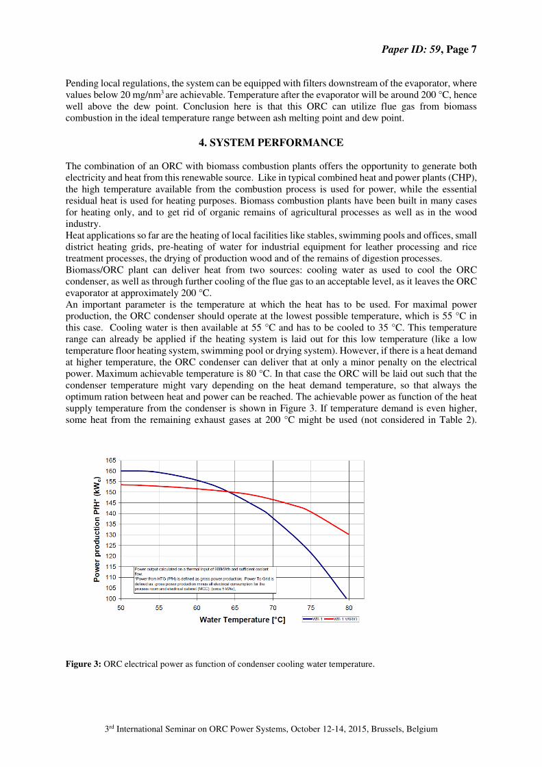
optimum ration between heat and power can be reached. The achievable power as function of the heat
supply temperature from the condenser is shown in Figure 3. If temperature demand is even higher,
some heat from the remaining exhaust gases at 200 °C might be used (not considered in Table 2).
Figure 3: ORC electrical power as function of condenser cooling water temperature.
Paper ID: 59, Page 8
3rd International Seminar on ORC Power Systems, October 12-14, 2015, Brussels, Belgium
Of course, apart from delivery temperature, the amount of required heat can vary over time. Lower heat
load might be accommodated by part load operation of the ORC by reducing heat input or by rejection
of the excess heat. Some examples of typical performance specifications are given in table 2 blow.
Table 2: Biomass combustion plants using ORC for electricity production (indicative values)
CHP mode POWER optimized
Burner power kWth ~ 1100 ~ 1100
ORC heat input kWth ~ 900 ~ 900
Stack losses (if unused) kWth ~ 200 ~ 200
Power output ORC kWe 130 170
Heat rejected in coolant kWth ~ 650 ~ 650
Coolant outlet temperature ˚C 80 55
General losses
(mechanical and electrical)
kWth ~ 100 ~ 100
ORC electrical Efficiency % ~14,5 ~18,9
CHP electrical efficiency % ~11,8 ~15,5
CHP system efficiency % ~70,9 ~74,6
5. CONCLUSIONS AND OUTLOOK
Because of the urge for renewable power and optimal use of all sources of energy, the application of
combined heat and power should be realized in as much as possible instances. Thanks to the availability
of ORC technology, this is now possible in cases where biomass is being used for heating and drying
purposes. A different, counter intuitive, view on CHP is needed. The market asks for a system that first
and foremost produces the demanded amount of heat energy, the electricity production should follow.
This makes the electricity the byproduct and not the heat, as customary when a power station delivers
also heat.
Local availability of solid biomass combined with local heat demand urges for tuning plant size to their
volumes, avoiding large distances for biomass transportation and extensive heat networks. Moreover,
the general tendency to more decentralized power generation is facilitated by the development of smart
grid technology.
The whole system should be flexible for the ratio between heat and power. Varying heat demand, for
example from seasonal effects or the needed temperature for drying (pending e.g. moisture content),
can in this case be accommodated while ensuring maximum system efficiency through the VARIO®
concept.
Evaporator cleaning is still a challenge, as the character of the dust deposit may vary largely with the
kind of biomass and combustion technology used. So far, different cleaning methods have been applied
successfully, on the basis of experience gained. A more sophisticated engineering approach should be
developed.
References
J.P. van Buijtenen et al: DESIGN AND VALIDATION OF A NEW HIGH EXPANSION RATIO
RADIAL TURBINE FOR ORC APPLICATION, 5th European Conference on Turbo-machinery,
Praha, March 2003
Paper ID: 59, Page 9
3rd International Seminar on ORC Power Systems, October 12-14, 2015, Brussels, Belgium
J.P. van Buijtenen: THE TRI-O-GEN ORGANIC RANKINE CYCLE: DEVELOPMENT AND
PERSPECTIVES, Power Engineer, Journal of the IDGTE, March 2009, Volume 13 Issue 1.
J. Heinimo, J.P. van Buijtenen, J. Larjola, J. Backman: SMALL ELECTRICITY PRODUCTION WITH
HIGH SPEED ORC TECHNOLOGY. International Nordic Bioenergy 2003 conference, Jyvaskyla, 2/5
September 2003
S. van Loo, J. Koppejan: THE HANDBOOK OF BIOMASS COMBUSTION & CO-FIRING.
Published by Earthscan Ltd, Dunstan House, 14a St Cross Street, London ECIN 8XA, UK. ISBN: 978-
84407-249-1. (2008)
ACKNOWLEDGEMENT
The authors wish to thank the management of Triogen B.V. for their permission to publish this paper.