AFWAL-TR-81 -20087A 1'A SMALL TURBINE ENGINE AUGMENTOR Phase I - Preliminary Design Studies of Afterburner and Duct-Burner Configurations. T. E. Kuhn, T. W. Bruce, and H. C. Mongia Garrett Turbine Engine Company 111 South 34th Stieet, PO. Box 5217 Phoenix, Arizona 85010 March 1981 Technical Report A-V %-TR-81-2008 Interim Report for Period 1 August 1980 - 29 October 1980 Approved for public release; distribution unlimited LAJ Prepared for k I Aero Propulsion Laboratory AIR FORCE WRIGHT AERONAUTICAL LABORATORIES AIR FORCE SYSTEMS COMMAND A Wright-Patterson AFB, Ohio 45433 ,o~I A < -
Transcript
AFWAL-TR-81 -20087A
1'A
SMALL TURBINE ENGINE AUGMENTORPhase I - Preliminary Design Studies of Afterburner and Duct-Burner Configurations.
T. E. Kuhn, T. W. Bruce, and H. C. MongiaGarrett Turbine Engine Company111 South 34th Stieet, PO. Box 5217Phoenix, Arizona 85010
March 1981
Technical Report A-V %-TR-81-2008Interim Report for Period 1 August 1980 - 29 October 1980
Approved for public release; distribution unlimited
LAJ
Prepared for k
I Aero Propulsion LaboratoryAIR FORCE WRIGHT AERONAUTICAL LABORATORIES
AIR FORCE SYSTEMS COMMAND AWright-Patterson AFB, Ohio 45433
,o~I A < -
r!
NOTICE
When Government drawings, specifications, or other data are used for any purposeother than in connection with a definitely related Government procurement operation,the unu ed States Government thereby incurs no responsibility nor any obligation [whatsoever; and the fact chat the gcvernment may have formulated, furnished, or :n
any way supplied the said drawings, specifications, or other data, _,s not to be re-garded by implication or otherwise as in any manner licensing the holder or anyother person or corporation, or conveying any rights or permission to rdnufrlctureuse, or sell any patented invention that may -;n any way be related thereto.
This reoort :as been reviwed by the Office of Public Affairs (ASD/?A) and Zsreleasable to the National rechnical Information Service (NTIS). At NT:S, i: wil&be available to the genera- public, including fore,.gn nations.
This technical report has been reviewed and is approved For publication.
ELMER E. BUCHANAN ERIK. W. LINDNER, Technical Area ManagerProject Engineer Special Engine TechnologyPerformance Branch Performance BranchTurbine Engine Division Turbine Engine Division
FOR T'A COMMAKDER
DAVID H. QUICK, Lt Col, USAFActing Di rectorTurbine Engine Division
Z_ your address as changed, if you wish 1o be removed from our TUaiing is:, orLf the addressee is no longer employed by your organization please not;f.YAFWAL/POTAW-PAFB, OH 45433 to help us maintain a current maiing list".
Coies of this ,eport should not be returned unless return is requlzed by secur'ty P=orsldezations, contractual obligations, or notice on a specific document.
/qlum 21R DOCUMENTATION PAGE RZAPAGE S Oins 5
5GOVT AC 3.IC IDEOO 'iC0M~Zo~NG FR
~, FWLTR-81-2Q8 A5
(& $MALL TURB NE ENGINE AUGMENTOR, iInterim n,11echnica. Ypth fP~hase Z.w Prelimin'ry Design StudiesAllo ?qOcAfterburner and nuct-Burner aev4&~'
Aero Propulsion Laboratories Pl// ~ark-81(AFWAL/POTA) i---*rsI. m~kati OP 0#ags
Wriaht-attesnAPOi 4543114. OMSOEIN AGNCY AMES AOAE 1iffW E Im men( Canu"Iiw4d O1lS..) 4. 9ICRSTY CLAI (0. 1 A#& pope"
UNCLASS IFIlED.0. OECCLA1IPEICA TION DOWOOGRADING
Approved for public release; distribution unlimited.
20. SUPPI.ENINV~qY 600 WO-
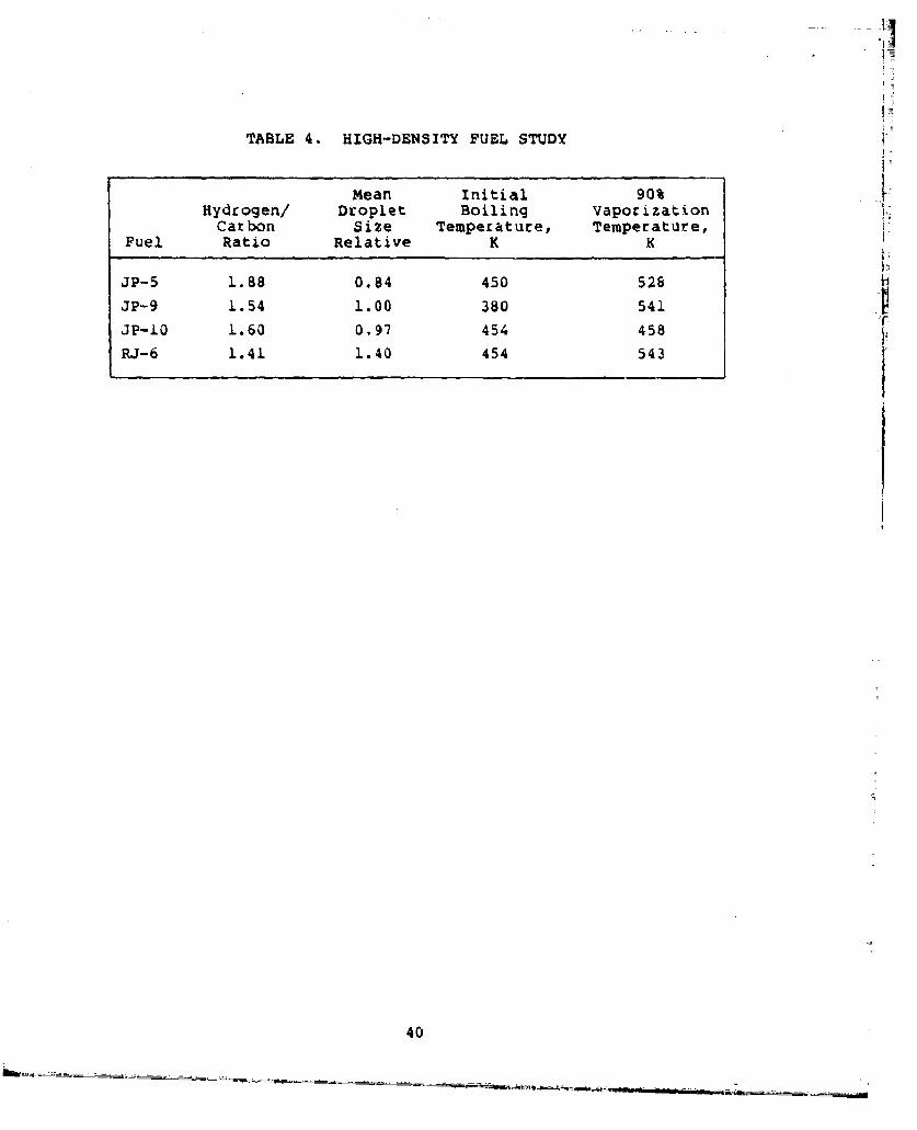
AFTER3tJRNER, DUCT-BURNER, AUGMENTOR, CRUISE MISSI LE, TURBOFAN,HIGH.-DENSITY FUEL
St. A ST AACT rComfh. m~ - .w. e@ 41 Of .e08eV'" Iddegfif Or 6104h is06.)
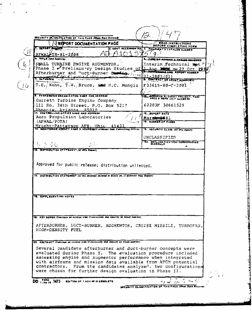
Several zandidate afterburner and duct-burner concepts wereevaluated during Phase I. The evaluation procedure includedassessing engine and augmentor performance when integratedwith airfrarre and mission data available from ATC.M potentialcontractors. Frum the candidates analyze', two confiaurationwere chosen for further design evaluation in Phase II.
DO, 1473 am-room or I o a III LET o5501 ISZCUj~uTV CLASSFICATION Of THII PAGEL (WN..w Pi. age., / Ior
SUMMARY
Several candidate afterburner and duct-burner concepts were
evaluated. The evaluation procedure included assessing engine
and augmentor performance when integrated with airframe and
mission data available from ATCM potential contractors. From the
candidates analyzed, two configurations were chosen for further
design evaluation.
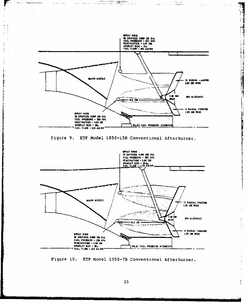
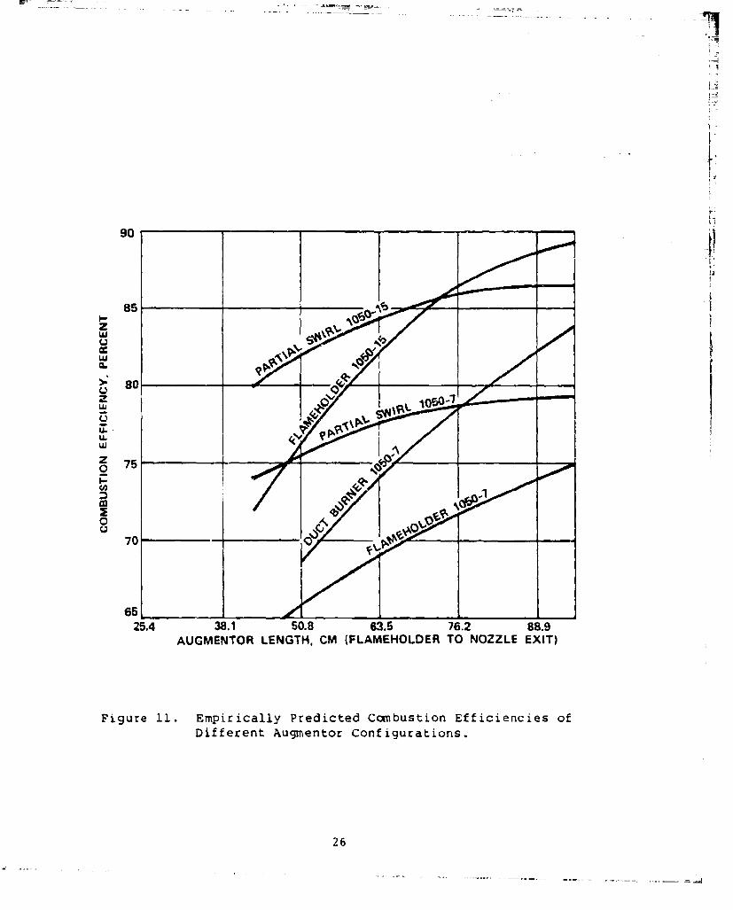
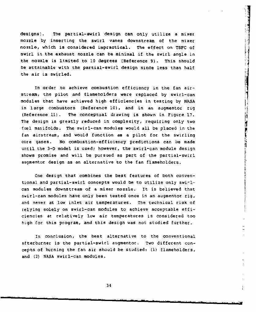
Of the several augmentor concepts screened, the conventional
flameholder with mixer-nozzle and the partial-swirl augmentor
were determined to produce the highest combustion efficiency with
the least impact on the size or performance of the core engine.
These two designs were therefore selected for detail analysis.
Two engines were evaluated for use in augmented cruise
missiles. The lower-bypass-ratio engine was selected because of
its smaller diameter, similarity to the Boeing ALCM-L engine, and
greater suitability for augmentation.
The effect of using JP-10 and RJ-6 fuels was predicted to be
small, but carbon-slurry fuel will require extensive modifica-
tions to the fuel manifold.'
/ /
1/
PREFACE
The Small Turbine Engine Augmentor Program is being con-ducted by the Garrett Turbine Engine Company, a division of The
Garrett Corporation, for the Air Force Wright Aeronautical
Laboratories, under Contract F33615-80-C-2001.
The program is being conducted under the direction of
Mr. Elmer Buchanan, Project Engineer, AFWAL. The Garrett Program
Manager and Principal Investigator are Mr. T. W. Bruce and
Dr. H. C. Mongia, respevtively. Key contributors to the program
are Mr. T. E. Kuhn, who is responsible for the augmentor detailed
Aero/Thermo analysis, design, and development testing; and
Mr. J. V. Davis, who conducts the airframe integration and engine
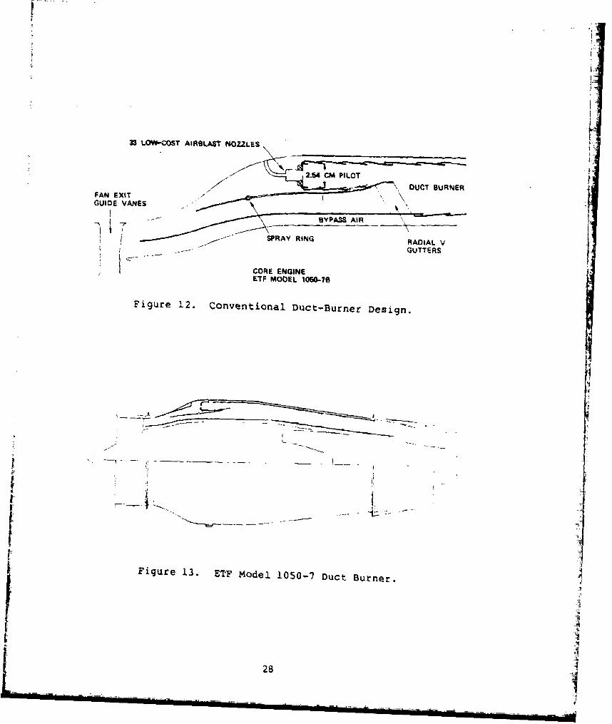
Common to all engine concepts under consideration that
employ augmentation are the requirements that the concepts mini-
mize fuel consumption at cruise power settings and minimize
engine diameter. Vehicle gross weight and range are extremely
sensitive to these requirements. The minimum-diameter require-
ment tends to drive the engine towards a lower bypass ratio than
would be selected on an independent basis.
Based upon mission analyses conducted with the Boeing
Company, the cruise-missile engine will be subsonically operated
at a specified percentage of military thrust for 80-percent of
the mission duration in order to provide sufficient dry thrust
for terrain following. This mission, which is supported by the
McDonnell Douglas Astronautics Company (MDAC) and the Corvair
Division of General Dynamics (GDC), influences the engine fan
pressure ratio selection, and hence bypass ratio. Additionally,
the engine should be optimized for low fuel consumption at the
predominant specified percentage of military thrust.
The maneuvering mission was selected as the basis for aug-
mentor selection considerations. The augmentor requirements for
this mission are considered to be consistent with the technology
of the proposed advanced engines (1983 to 1985 technology level).
The supersonic dash mission was considered to have augmentor and
system requirements that would be consistent with a 1990 to 1995
7
technology level. The manuevering mission consists of a long
range s _ sonic cruise with jinking maneuvers, as necessary for
threat avoidance. The augmentor is in the dry mode for cruiseand in the augmented mode for jinking. An augmentation ratio of
2.0 is required for the maneuvering mission for jinking. The
augmentor temperature rise during the augmented mode is 1144K.
The baseline Garrett engine that was initially evaluated at
GDC is the ETF Model 1050-12. This engine is a low (1.1) bypass
ratio, two-spool turbofan, and is well suited for an afterburner.
A duct burner would not provide enough augmentation ratio due to
the low-bypass-ratio level of this engine. Subsequent discus-
sions with GDC resulted in the selection of higher bypass ratios
than that of the ETF Model 1050-i2. An engine bypass ratio
between 1.5 and 2.5 provides acceptable range characteristics,
and also offers lower IR signatures than the ETF Model 1050-12.
Consequently, two engines were used for engine/airframe integra-
tion efforts in order to select the optimum engine-augmentor
configuration, the ETF Models 1050-15B and the i050-7B. Unin- V
stalled, dry engine performance characteristics for these two
engines are given in Table L. Selection of the optimum engine-augmentor required additional engine/airframe integration
efforts, and will be discussed in Paragraph 2.7.
2.2 Empirical Augmentor Model Description
An empirical model was adapted to calculate combustion
efficiency and pressure loss for an afterburner with flame-
holders.
For an initial design, only the desired temperature rise,
inlet airflow, temperature, and pressure are known. The aug-
mentor fuel/air ratio required for a given temperature rise is a
function of the combustion efficiency, which in turn, is influ-
enced by the fuel/air ratio. The solution is an iterative
8
process, with the value of fuel/air ratio being assumed and then
corrected until the calculated temperature rise matches the
desired value. The calculation of combustion efficiency from the
selected inlet conditions, afterburner length, and fuel/air ratio
follows the work by Petrien et.al. (Reference 1), as described
in the following paragraphs.
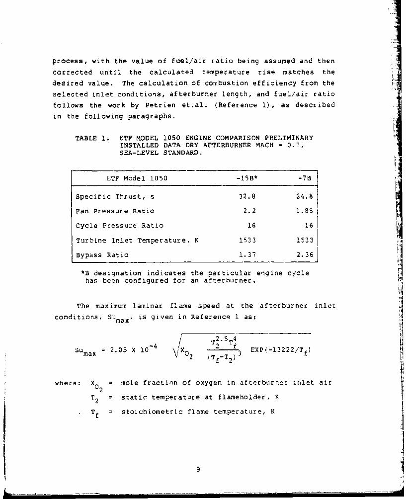
TABLE 1. ETF MODEL 1050 ENGINE COMPARISON PRELIMINARYINSTALLED DATA DRY AFTERBURNER MACH = 0.7,SEA-LEVEL STANDARD.
ETF Model 1050 -15B* -7B
Specific Thrust, s 32.8 24.8
Fan Pressure Ratio 2.2 1.85
Cycle Pressure Ratio 16 16
Turbine Inlet Temperature, K 1533 1533
Bypass Ratio 1.37 2.36
*B designation indicates the particular engine cycle
has been configured for an afterburner.
The maximum laminar flame speed at the afterburner inlet
conditions, Sumax , is given in Reference 1 as:
- r TSumax = 2.05 X 10 02 (TfT2)3 EXP(-1 3222 /Tf)
14
where: Xo mole fraction of oxygen in afterburner inlet air
T static temperature at flameholder, K
T f =stoichiometric flame temperature, K]
9IMI
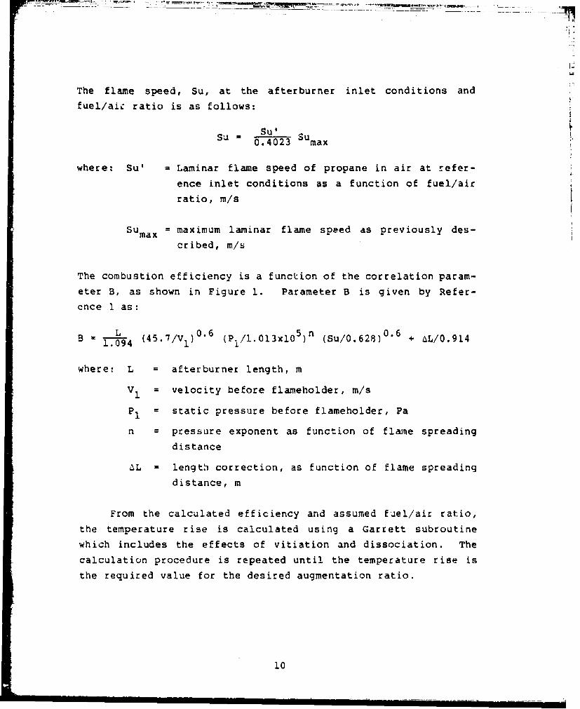
The flame speed, Su, at the afterburner inlet conditions and
fuel/aic ratio is as follows:
Su'
0.4023 max
where: Su' a Laminar flame speed of propane in air at refer-
ence inlet conditions as a function of fuel/air
ratio, m/s
SUmax = maximum laminar flame speed as previously des-
cribed, m/s
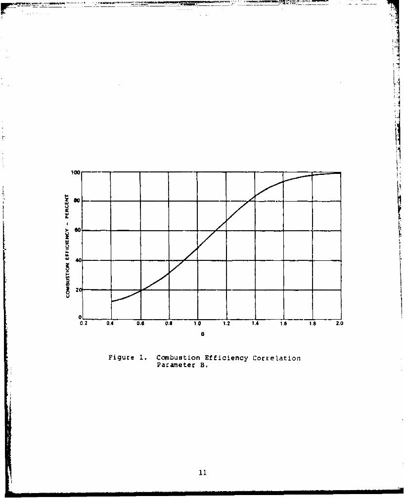
The combustion efficiency is a function of the correlation param-
eter B, as shown in Figure 1. Parameter B is given by Refer-
ence 1 as:
L 4. 0.6 5 n 0.6+6/.1B = Y.094 (45.7/V . ) (PI/1.013x105) (Su/0.628) + AL/0.914
where: L = afterburner length, m
V 1 velocity before flameholder, m/s
P1 = static pressure before flameholder, Pa
n = pressure exponent as function of flame spreading
distance
aL = length correction, as function of flame spreading
distance, m
From the calculated efficiency and assumed fuel/air ratio,
the temperature rise is calculated using a Garrett subroutine
which includes the effects of vitiation and dissociation. The
calculation procedure is repeated until the temperature rise is
the required value for the desired augmentation ratio.
10
100.
[ _ _
IA.
" 40
20
02 0.4 0.6 0.8 1,0 1.2 1.4 1.6 I. 2.0
Figure 1. Combustion Efficiency CorrelationParameter B.
=1
The program also computes the dry and momentum pressure
losses by assuming each loss occurs separately and adding the two
losses together. The error involved in not treating the losses Vtogether is considered to be small. Standard expressions for
friction, diffusion, and momentum losses are used. Flameholder
blockage losses are taken from Kumar (Reference 2), and the
equation is as follows:
CD 4 B2 (2-B) /Ysin /2/(I-B)2
where: CD = loss co-efficient
B = flameholder geometric blockage
e = included angle of V-gutter
2.3 Fuel-Injection Model Description
A fuel-injection computer program was written to calculate
the penetration, spread, and droplet size of liquid jets for
cross-stream injections into high-velocity airflows. The expres-
sion for droplet size, termed the Sauter mean diameter (SMD), is
taken from Ingebo (Reference 3):
0.25SMD = 3.9 do (We/R e )
where: do = orifice diameter, same units as SMD
Rd aOV2 Weber number, dimensionlessWe a 7/ a a
Re = doVa/v Reynolds number, dimensionless
0- a fuel surface tension
Pa = air density
Va = air velocity
V - fuel kinematic viscosity
12
Ingebo varied the liquid velocity from 24 to 61 m/s and found no
significant change in SMD.
The expression for jet penetration (perpendicular to airflow
direction) was taken from work done at AFAPL (Reference 4), and
is as follows:
Y/do = 2.1 - (x/d0 )0 .2 7
where: Y = penetration distance
q = pV2 /pa V2aa
P = fuel density
V = fuel velocity
X = axial distance downstream
This expression yields penetration close to the predictions
of Schitz and Padhye (Reference 5), but only for large values of
x/d0 (>100). The range of interest of x/d0 is from 75 to 150 for
this design study, so the discrepancy between the two expressions
is typically small. The following expression for the spread or
fanning out of the jet as it moves downstream is also extracted
from Reference 4.
Z/do = 6.95 (x/d0 )0 .33
where Z = spread of jet
2.4 Conventional Afterburner Evaluation
The following parameters are evaluated for their effect on
augmentor performance in both the high- and low-bypass-ratio
engines: (1) fuel staging zone size, (2) flameholder geometry,
(3) fuel injection system, and (4) inlet Mach number.
13
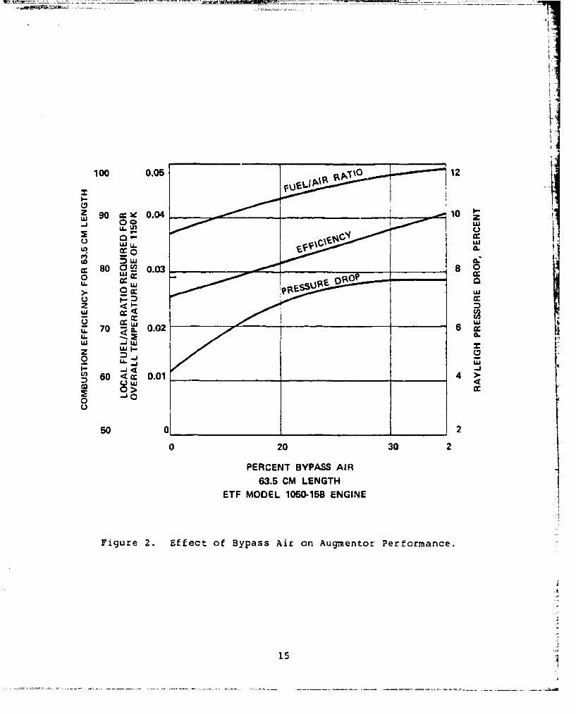
The desired temperature rise of the augmentor of the ETF
Model l050-15B engine at an augmentation ratio of 2.0 is 1150K.
Assuming ideal conditions, the overall fuel/air ratio is only
0.028, which is below or near the blowout fuel/air ratio of most
conventional afterburners. Therefore, the combustion process for
a conventional-flameholder afterburner for small turbine engines
must be confined to only a portion of the airstream. Increasingthe local fuel/air ratio provides margin over the lean-blowoutlimits and improves combustion efficiency. In addition, aug-
mentor liner life can be significantly improved by providing a
cooler air film in contact with the liner surfaces. However,
high temperature rises in the burning portion of the airstream
produce high Rayleigh (heat addition) losses. Also, if there is
not sufficient mixing between the combustion gases and the bypass
air, the exhaust-nozzle thrust coefficient may decrease as much
as 2 percent (assuming no mixing). Therefore, theLe is an opti-
mum amount of air which should be allowed to bypass the com-
bustion process.
The effect of the amount of bypass air on combustion
efficiency, local fuel/air ratio, and pressure drop is shown in
Figure 2 for the ETF Model 1050-15B. A value of 20-percent
bypass air was chosen because the efficiency and lean-blowout
margin are adequate, and higher bypass percentages would decrease
the mixedness of the exhaust gases and lower the nozzle thrust.
A value of 20 percent was also found to be optimum for the ETF
Model 1050-7B afterburner.
From experience and theoretical considerations it is
known that little improvement in combustion efficiency is
achieved beyond 35-percent flameholder blockage. A number of
f lameholder configurations were evaluated including single
annular gutter, double annular gutter, and a single annular
gutter with finger-gutter arrangement. Experience on large
afterburners has shown that V-gutter width and approach Mach
t 14
Ilk.
U. L.
0 L 0.03 8120
C.) LU
X 0lU. -
z MI
.0 <. 0.02
2
00
0 20 30 2
PERCENT BYPASS AIR63.5 CM LENGTH
ETF MODEL 1050-158 ENGINE
Figure 2. Effect of Bypass Air an Augmentor Performance.
15
number are closely related in regard to lean blowout and com-
bustor efficiency. For given inlet conditions, it directly
related to the time the fresh unburned fuel-air mixture stays in
contact with the hot ignition gases from the flameholder wake.
With everything else remaining the same, the minimum allowable
width is directly proportional to the approach Mach number. The
majority of the V-gutters used on large afterburners have widths
of approximately 3.8 cm, with a few as low as 3.2 cm for the
lower end of the approach Mach number. With still lower Mach
numbers, such as in a duct burner designed by G.E. under NASA
sponsorship (Reference 6), V-gutters with 1.9 cm width have
been successfully used.
For the preliminary study phase of the present program, a
minimum allowable width of 3.2 cm was considered acceptable.
Detailed analysis and element testing (if undertaken) during
Phase I will establish criteria for a minimum acceptable gutter
width in regard to lean blowout, combustion efficiency, and dry
pressure loss.
A single annular gutter with 35-percent blockage,
located midway between the center and wall of the afterburner,
was predicted to have a low combustion efficiency and a high lean
blowout fuel/air ratio. A two-annular-gutter configuration with
3.2 cm gutter width gave blockage more than 35 percent, and
therefore was dropped from further considerations.
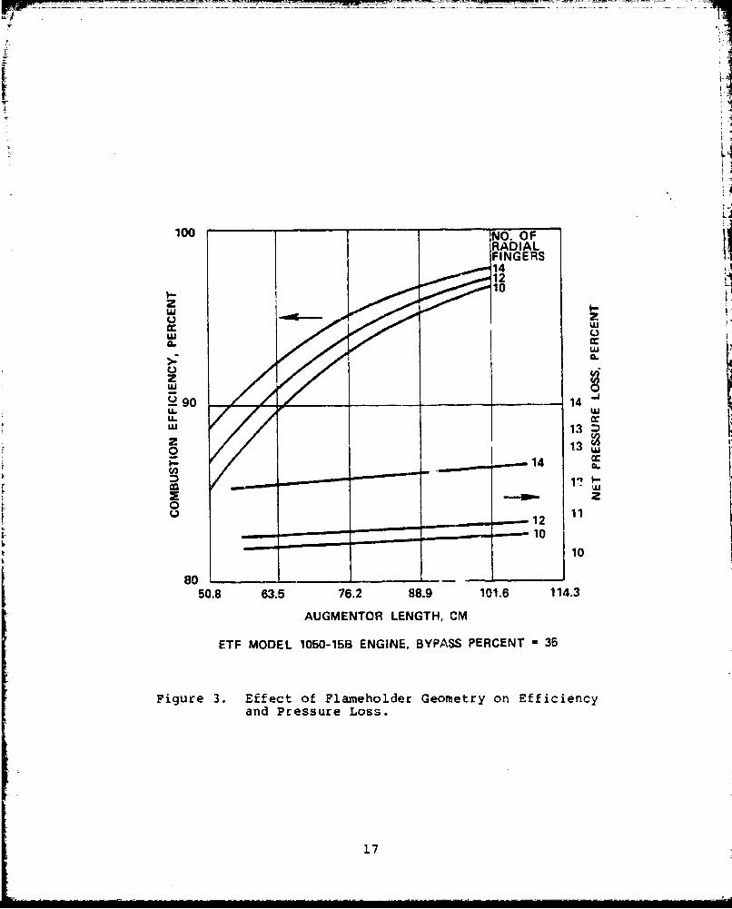
A majority of initial design iterations were therefore
done on the flameholder configuration incorporating a single
annular gutter with radial fingers. The effect of the radia3.-
finger design features, such as the number and the split between
the inner and outer flow streams, height, width and swept back
angles in the afterburner performance were evaluated qualita-
tively and quantitatively, where possible. Figure 3 presents an
16
t4
:i:i~T:T~: :I... I : f f ... l ...i ii~~l I
RAIAFINGER
44z I
wj 0
>: CL
0
29 go__ 14
U.-
z 1201
01
50.8 63.5 76.2 88.9 101.6 114.3
AUGMENTOR LENGTH, CM
ETF MODEL 1050-15B ENGINE, BYPASS PERCENT - 35
Figure 3. Effect of Flameholder Geometry on Efficiencyand Pressure Loss.
17
example of this phase of the activities. The combustion effi-
ciency and pressure losses were calculated empirically as influ-
enced by the number of radial fingers. Although the combustion
efficiency is shown to improve monotonically with the increasing
number of radial fingers, a trade-off needs to be made to keep
the pressure drop within an acceptable limit. For the ETF
Model 1050-15B augmentor, Vigure 3 indicates that optimum per-
formance can be achieved by using a single annular gutter with
12 radial fingers.
A typical preliminary design iteration for the fuel-
delivery system consists of the design of spray rings/bars
including the number and sizes of the orifices, the attendent
fuel-pressure drop, and penetration and spreading of the spray
plumes. Vpny considerations including installation, structural
durabilitl, and blockage must be taken into account in order to
select any of the three types of fuel-delivery arrangements:
spray rings, spray bars, and a combination of rings and bars. A
limited number of layout sketches for the small turbine engine
augmentor indicated that for a large number of orifices, spray
rings are preferable; whereas, for less than 20 orifices, spray
bars are more desirable. As explained in the following para-
graphs, the ETF Models 1050-7 and -15 afterburner require 108 and V83 orifices, respectively. Therefore, spray rings were selected bfor application in the small turbine engine augmentor.
The size and the number of orifices is decided by a
number of design requirements including fuel distribution and
minimum and maximum fuel-pressure drops. The number and size of
the orifices should be a maximum to increase the spread of the
fuel jets and decrease the circumferential variations in local
fuel/air ratio. The number and size of the orifices should be
minimized for fuel pressure, fuel droplet size, and penetration
considerations. The calculated effect of the orifice diameter on
fuel-pressure drop, droplet size, and spray penetration and speed
is shown in Figure 4. A series of such curves was generated for
1.8I|
FUEL PRiSSURE
12 PENETRATION ______ 3.
00
cc 40 w
N <
3 0
o z4ct I 168.9W
z 0wj20~
DROPLET
0t 00.05 1 0.064 0.076
ORIFICE DIAMETER, CM58 ORIFICES
ETF MODEL 1050-15B ENGINE INNER SPRAY RING
Figure 4. Spray-Ring Design Parameters as Function ofOrifice Diameter.
19LI
different numbers of orifices. These calculations showed that
the smallest orifice size was not necessarily the best for
achieving a uniform fuel-air distribution. An orifice diameter
of 0.53 mm was found to be optimum, and is recommended for fur-
ther evaluation.
The axial location of the spray rings is decided by many
considerations, including spray penetration and spread, degree of
prevaporization required, and rumble. A preliminary study of the
axial position of the fuel spray rings was therefore conducted by
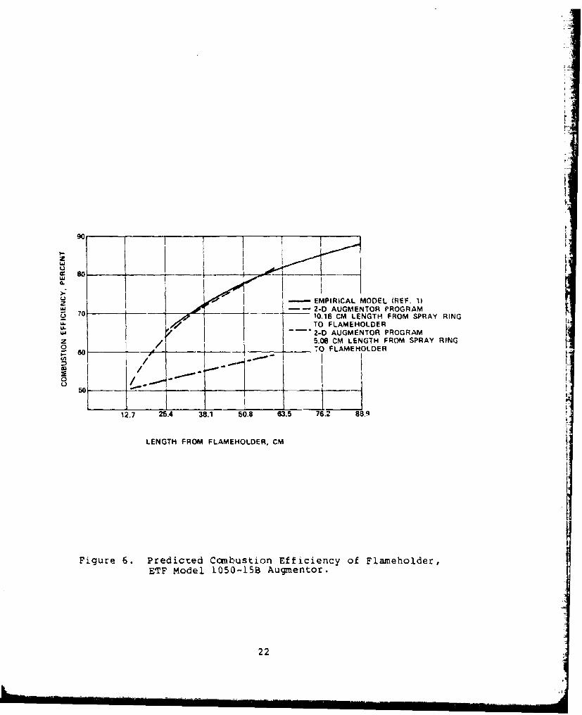
using the 2-D augmentor model. The ETF Model 1050-15B augmentor
was modeled as shown in Figure 5 for the plane in between the
radial fingers. The axial direction (X-nodes) continue out to
61 cm from the flameholder. Two cases were run with the 2-D
model: (1) the 10.2 cm injection length with pilot burner at the
core as shown in Figure 5, and (2) with the flameholder moved to
within 5.1 cm of the spray rings and the pilot burner removed.
The predictions of combustion efficiency for the two different
lengths from the spray ring to the flameholder are given in Fig-
ure 6 and shows that the combustion efficiency was considerably
reduced with the 5.1 cm injection length. More analytical study
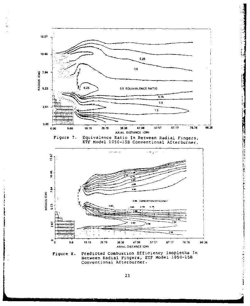
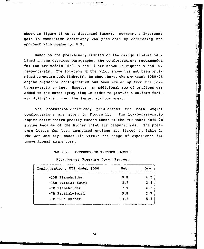
is planned. A computer plot of the fuel/air ratio profiles of
the ETF Model 1050-15B augmentor with a 10.2 cm injection
length is shown in Figure 7. The fuel/air ratios near the
core are nearly three times the values on the outside of the
V-gutter, resulting in low combustion efficiencies near t.he core
(as shown in Figure 8). The fuel flow to each spray ring should
therefore be adjusted, and optimum split can be obtained by using
the 2-D model.
The approach Mach number of the initial high-bypass-ratio
engine afterburner (ETF Model 1050-7 configuration) was main-
tained at 0.23 in order to stay within the engine envelope.
Since this is higher than the Mach number used in larger after-
burners, the predicted combustor efficiency of the ETF
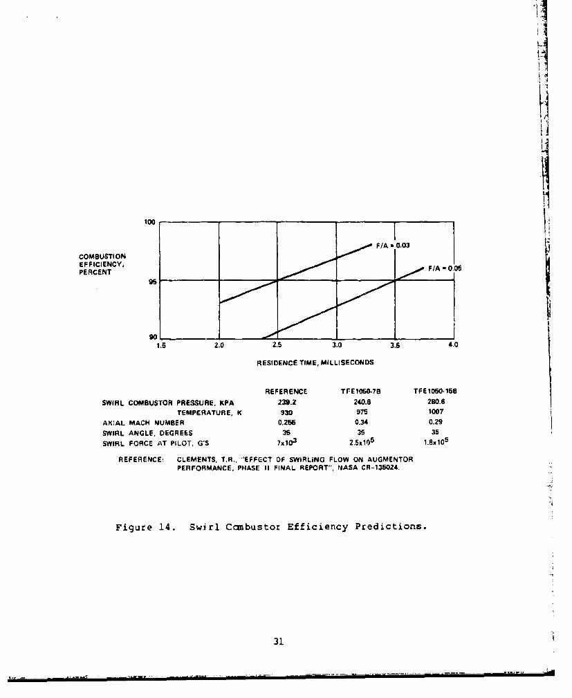
Model 1050-7 afterburner was lower than the -15 configuration (as