Deck-Framing Strategies Ledger brackets, flexible flashing, and a joist-hanger jig are a few field-tested tricks for overcoming construction challenges I love building decks. If I had to pick one part of the house that I enjoy building the most, it’s the deck. There’s no rush to dry it in so that other subs can work, it’s a straightforward outdoor project, and we’re heroes when the job is finished. Lately, my decks have been getting better as I find better ways to use new products and techniques that extend the life of the deck and its host structure. Design a layout that’s strong and relatively simple There are numerous ways to design and frame a deck structure, which typi- cally consists of the footings, the posts, the beams, the ledger, and the joists. I like to use framing layouts that suit the deck design and simplify the framing as much as possible. This project consisted of a 900-sq.-ft. wraparound deck that began 8 ft. above the walkout portion of a finished basement and patio, and ended at grade level at the back door. Instead of building a deck frame cantilevered over a carrying beam, I incor- porated the load-bearing characteristics into a rim beam made of a doubled 2x12 to maximize the headroom and to reduce the need for a forest of support posts. The wider rim also would later help to conceal a deck drainage system that I would install before the decking went down. Mike Guertin lives in East Greenwich, R.I. His Web site is www.mike guertin.com. Photos by Charles Bickford, except where noted. BY MIKE GUERTIN Smart FINE HOMEBUILDING 80 Photos top right, center, facing page: Mike Guertin. Photo left facing page: Krysta S. Doerfler. COPYRIGHT 2008 by The Taunton Press, Inc. Copying and distribution of this article is not permitted.
Transcript
Deck-Framing StrategiesLedger brackets, flexible flashing, and a joist-hanger jig are a few field-tested tricks for overcoming construction challenges
I love building decks. If I had to pick one part of the house that I enjoy building the most, it’s the deck. There’s no rush to dry it in so that other subs can work, it’s a straightforward outdoor project, and we’re heroes when the job is finished. Lately, my decks have been getting better as
I find better ways to use new products and techniques that extend the life of the deck and its host structure.
Design a layout that’s strong and relatively simpleThere are numerous ways to design and frame a deck structure, which typi-cally consists of the footings, the posts, the beams, the ledger, and the joists. I like to use framing layouts that suit the deck design and simplify the framing as much as possible. This project consisted of a 900-sq.-ft. wraparound deck that began 8 ft. above the walkout portion of a finished basement and patio, and ended at grade level at the back door.
Instead of building a deck frame cantilevered over a carrying beam, I incor-porated the load-bearing characteristics into a rim beam made of a doubled 2x12 to maximize the headroom and to reduce the need for a forest of support posts. The wider rim also would later help to conceal a deck drainage system that I would install before the decking went down.
Mike Guertin lives in East Greenwich, R.I. His Web site is www.mikeguertin.com. Photos by Charles Bickford, except where noted.
BY MIKE GUERTIN
Deck-Framing Deck-Framing Smart
FINE HOMEBUILDING80 Photos top right, center, facing page: Mike Guertin. Photo left facing page: Krysta S. Doerfler.
COPYRIGHT 2008 by The Taunton Press, Inc. Copying and distribution of this article is not permitted.
CHALLENGE The first challenge in any deck project is mounting and flashing the ledger to the building. Ledgers conven-tionally bolted to the wall framing usually demand a flashed break in the siding, a time-consuming method that’s often not weathertight or rot-resistant.
STRATEGY On this deck, I used heavy-duty aluminum brackets from Maine Deck Brackets; I find them ideal for shingle sid-ing. The beam-shaped sections are bolted directly to the house’s rim joist. In turn, the deck ledger is bolted to the bracket’s outer flange. To make the bracket’s point of attachment as solid and as waterproof as possible, I first strip back five courses of shingles to create a space about a foot wide. I then lift up a flap of building paper and cut a rectangle in the sheathing. I line the back of the sheathing cutout with a self-sealing flashing tape like Grace’s Deck Protector (www.na.graceconstruction.com). After the flange is mounted, I sur-round and lap onto the sides of the web with flashing tape for an effective seal. The tape directs water to the top lap of the shingle course beneath. Once the head flap of builder’s felt is back in place, the seal is water-resistant. An additional bead of caulk can be applied between the siding and the bracket’s web.
My associate, Mac, and I spaced the deck brackets on approximate 40-in. centers so that we could use a single 2x8 to span between them. To keep the bolt holes away from the ledger butt joints, we positioned joints between brackets and used Ledger Lock screws (www.fastenmaster.com) to connect a 3-ft.-long splice board on the back side of the primary ledger.
Beefy brackets separate the ledger from the wall
Create a space for the bracket flange. After stripping back the shingles and a flap of builder’s felt, I mark and cut out a section of sheath-ing directly over the rim joist.
Brackets demand through-bolts, not lags. After drilling the pilot holes, I flash the cutout and bolt the bracket, which requires access to the other side of the rim joist.
Redundant overlaps are the best waterproofing. Con-sidering the consequences, it’s best to flash and to coun-terflash behind, around, and over the brackets.
Labeling simplifies reassembly. I num-ber each shingle with its course and position as I remove it, which makes reinstallation easier.
Use a spare bracket for bolt layout. Once the brackets are in place, we can trans-fer their locations to the ledger, drill pilot holes, and bolt the 2x into place. Any gaps around the exposed bracket web can be caulked (inset photo).
Maine Deck Brackets (www.deckbracket.com)
www.finehomebuilding.com JUNE/JULY 2008 81
COPYRIGHT 2008 by The Taunton Press, Inc. Copying and distribution of this article is not permitted.
CHALLENGE Manufacturers of pressure-treating chemicals have modified ACQ treatments or come up with new formulas that are less corrosive, and hard-ware manufacturers have improved their protective coatings. However, the potential for accelerated corro-sion still exists.
STRATEGY Choosing stainless-steel hardware or applying isolation membranes where hardware contacts wood can help a deck to last longer. Peel-and-stick flashing, staple-on plastic ribbon like York Wrap (www.yorkmfg.com), or even strips of #30 builder’s felt can be used as isolation membranes. We isolated each led-ger bracket by wrapping its outer flange. We also positioned 4-in.-wide strips on the rim joist and ledger at each hanger location, then wrapped the joist ends.
Flashing isolates galvanized joist hangers from possible corrosion
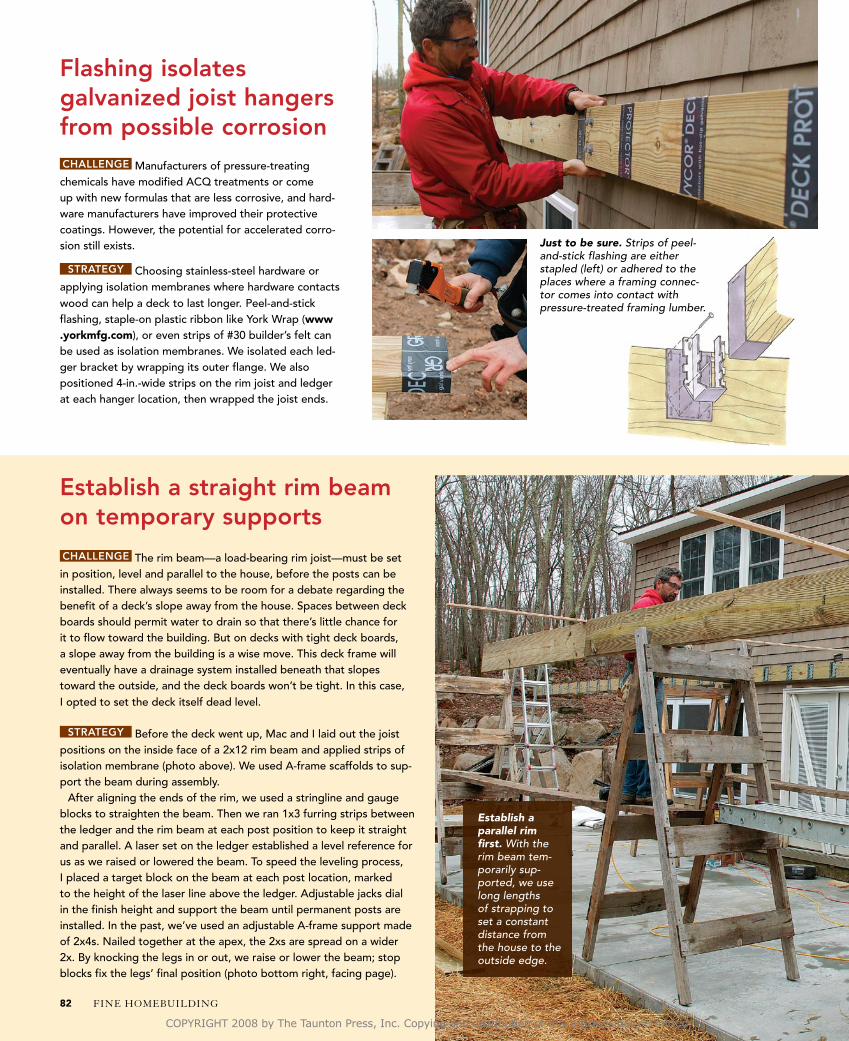
CHALLENGE The rim beam—a load-bearing rim joist—must be set in position, level and parallel to the house, before the posts can be installed. There always seems to be room for a debate regarding the benefit of a deck’s slope away from the house. Spaces between deck boards should permit water to drain so that there’s little chance for it to flow toward the building. But on decks with tight deck boards, a slope away from the building is a wise move. This deck frame will eventually have a drainage system installed beneath that slopes toward the outside, and the deck boards won’t be tight. In this case, I opted to set the deck itself dead level.
STRATEGY Before the deck went up, Mac and I laid out the joist positions on the inside face of a 2x12 rim beam and applied strips of isolation membrane (photo above). We used A-frame scaffolds to sup-port the beam during assembly.
After aligning the ends of the rim, we used a stringline and gauge blocks to straighten the beam. Then we ran 1x3 furring strips between the ledger and the rim beam at each post position to keep it straight and parallel. A laser set on the ledger established a level reference for us as we raised or lowered the beam. To speed the leveling process, I placed a target block on the beam at each post location, marked to the height of the laser line above the ledger. Adjustable jacks dial in the finish height and support the beam until permanent posts are installed. In the past, we’ve used an adjustable A-frame support made of 2x4s. Nailed together at the apex, the 2xs are spread on a wider 2x. By knocking the legs in or out, we raise or lower the beam; stop blocks fix the legs’ final position (photo bottom right, facing page).
Establish a straight rim beam on temporary supports
Just to be sure. Strips of peel-and-stick flashing are either stapled (left) or adhered to the places where a framing connec-tor comes into contact with pressure-treated framing lumber.
Establish a parallel rim first. With the rim beam tem-porarily sup-ported, we use long lengths of strapping to set a constant distance from the house to the outside edge.
FINE HOMEBUILDING82
COPYRIGHT 2008 by The Taunton Press, Inc. Copying and distribution of this article is not permitted.
Go by the string. To establish a straight rim, we put guide blocks on each end, run a string between, and adjust the distance by renailing the strapping.
Laser perfect. To gauge the height of the rim relative to the house, I set a laser level on the ledger and read the results on a marked target block.
I found some tall screw jacks (Post Shores; www.gostepup.com) to set the height of the rim beam on decks. In the past, we’ve also used a simple 2x A-frame (above) whose legs can be adjusted to raise or lower the beam.
CHALLENGE We had about 120 joist hangers on this project, so installing them as quickly and accurately as possible was crucial. Joist hangers can be attached to joist ends first, to the ledger and the rim joist first, or after the joists are tacked in position. I prefer to fasten the hangers to the ledger and the rim joist so that the joists can be dropped in quickly. There’s less struggling to hold joists flush before nailing, an important consideration when working off scaffolding.
STRATEGY Commercial versions are available, but I find that a simple T-jig takes 10 minutes to make and works best. Because we wrapped the joist ends with membrane, we needed a slightly wider-than-standard space between the sides of the hangers, so we ripped the leg of the T from 3⁄4-in. stock 111⁄16 in. wide. The 2x4 top registers against the top of the ledger. The leg’s bottom has eased corners to match the hanger profile; the hanger is seated tight and flat to the bottom of the leg.
We used a new metal-connector pneumatic nailer from Bostitch (www.bostitch.com) to drive the more than 750 11⁄2-in. or 21⁄2-in. nails and 500 3-in. nails needed to mount the hangers. These nailers pinpoint the holes stamped in the hardware and sink the nails pre-cisely. They saved us more than eight hours of tedious hammer work
Joist-hanger setup saves time
and paid for themselves twice on this job alone. To keep the joist tops flush, we checked the width of all the joists and pulled any that were 1⁄8 in. more or less than the average. (If we’d just pulled stock off the pile, narrower joists would be lower and wider ones higher because the hangers are all at the same level.)
When there are a lot of out-of-tolerance joists, we group them in like-size order and set their associated hanger heights so that the tops are flush. We lucked out on this job. The unit of 2x8s delivered had only two out-of-tolerance joists.
Keep the drudgery to a minimum. A jig to locate hangers and a dedicated nail gun save a day’s worth of labor.
TEMPORARY BUT ADJUSTABLE POSTS
Photo bottom right: Tom O’Brien JUNE/JULY 2008 83
COPYRIGHT 2008 by The Taunton Press, Inc. Copying and distribution of this article is not permitted.
CHALLENGE You can’t install the posts until the height and position of the rim beam are established.
STRATEGY With the rim beam straightened and braced, we squared up the frame and installed the end rim boards. We used adjustable wall braces to lock the frame in position, then plumbed down from the beam to the slab at each post position (about 8 ft. on center, spaced equally along the perimeter). After marking for the post bases, we drilled into the slab and used 5-in. by 1⁄2-in. wedge-type anchors to bolt down the bases. Post ends were wrapped with isolation membrane, then attached to the beam with galvanized connectors.
Install the posts in the right place
According to my engineer, 12-in.-dia. footings would
have sufficed for this soil type and deck load, but I chose plastic footing forms from Square Foot (www.sqfoot.com) to give the deck broader support. These forms provide more than four times the foot-ing area of 12-in.-dia. foot-ings. Also, because I knew it would be several weeks between the time I set the forms and the time we poured, I used 8-in.-dia. galvanized-steel ducts salvaged from a
Locate post bases. Plumbing down from the rim, I mark and drill holes for the post-base anchor bolts, then install the bases. With the post ends wrapped in isolation membrane, I set the posts in place.
Footing forms stay sturdy until you’re ready to pour
Double 2x12 rim beam takes the place of a support beam below.
2x8 ledger House
Compacted soil or gravel
22-in.-sq. footing form
8-in.-dia. galvanized-steel form
6-in. concrete slab
Local code specifies that footings must be 40 in. below grade (depths vary according to region and code).
1⁄2-in. reinforcing rod
Posts approximately 8 ft. on center
Ledger brackets on approximately 40-in. centers
FINE HOMEBUILDING84 Drawings: Martha Garstang Hill
COPYRIGHT 2008 by The Taunton Press, Inc. Copying and distribution of this article is not permitted.
CHALLENGE Deck framing is easier when the deck is close to the ground. When the deck is 8 ft. high and you have nearly 60 joists to install, it’s a big job to get this framing done efficiently without compromising safety.
STRATEGY We trimmed the joists 1⁄8 in. to 1⁄4 in. shorter than the span, which helped us to drop them in place without ripping the isolation membrane. There is a limit, however; joist ends can have no more than a 1⁄8-in. gap, according to the joist-hanger manufacturer. We set up planks between A-frame scaffolds to walk on and stacked enough joists to fill a plank-size section. With one crew member at each end, we dropped in the joists and drove in the diagonal nails through the hangers before moving the scaffold down for the next section. Once the joists were all nailed off, we cleaned up and got ready to run decking.
Work safer in the air
Framing approximately 16 in. on center 2x8 joists
Around the corner, where the deck was close to grade level, the old but sound concrete back steps interfered with several joists. We scribe-fit the joist ends to rest on the landing and added full-width support with a 2x4 sleeper. Fastened to the lower step with wedge-type anchors, the sleeper also acts as a base for toenailing joists.
INTEGRATE THE OLD WITH THE NEW
renovation project. I knew the steel wouldn’t soften or crush in the interim as cardboard tubes might. We poured a 6-in.-deep concrete slab beneath the deck area (see FHB #194, and FineHomebuilding.com) and tied the perimeter reinforcing rod and wire mesh to the vertical rods in each footing. Where the deck turned the corner, the footings were closer together, so I used only the salvaged ducts as tube forms without the larger footings.
Work a section at a time. After setting up stag-ing, we laid out and dropped the joists into the hangers, nailing them off as we went.
Visit the Magazine Extras section on our home page to learn more about protective isolation membranes.
FineHomebuilding.com
Because the deck is level, not sloped, the ledger can continue out to the rim beam. If the deck were sloped, a diagonal brace would be installed to handle the transition around the corner.
JUNE/JULY 2008 85www.finehomebuilding.com
COPYRIGHT 2008 by The Taunton Press, Inc. Copying and distribution of this article is not permitted.