TI DesignsSmart Electrical Meter Development Platform (SMB 3.0)Test Results
TI Designs Design Features• Modular and Scalable Smart MeterTI Designs provides the foundation that you need
Development Platform Helps Developersincluding methodology, testing, and design files toDesign Low-End to Advanced Smart Metersquickly evaluate and customize and system. TIfor AMR and AMI Systems.Designs helps you accelerate your time to market.
• Open Platform Lets Developers CustomizeDesign Resources their Designs for Further Development or
Differentiation.www.ti.com/tool/TIDM- Tools Folder with Design Files • ARM® Cortex™-M ApplicationSMARTMETERBOARD3
Connect to an IP Network so Customers canwww.ti.com/tool/cc2530emk CC2530Communicate with the Smart Meter througha Wi-Fi-Connected Computer, Smartphoneor Tablet, without the Additional Cost and
ASK Our E2E Experts Complexity of a Gateway.WebBench Calculator Tools
• Support for Low-Power RF (Sub-1GHz and2.4-GHz ZigBee) Implementations Connectsa Meter to a Home Area Network (HAN) forKit Contents and Requirements Short-Range Communication.
• Smart Meter Board + AC Power Coord • Easy Software Integration with Support for• SimpleLink™ CC3000 Wi-Fi Evaluation TI Smart Grid Software Libraries, including
Module ZigBee SEP 1.x and 2.0, WMBUS,802.15.4g, One-Phase/Two-phase• TRF7970A RFID Target Boardmetrology, THD, DLMS, Pre-Payment,• PLC Daughter Boards and Module MIFARE™ and Encryption.
• 2 CC2530 RF Transceiver Daughter Boards • Supports PLC for PRIME/G1/G3/P1901.2 for• IHD430, Low-Cost Segment Based In-Home Low-Frequency Narrowband
(MSP430AFE253) Payment of Energy.• Application Microcontroller Module
(Stellaris® LM3S1B21)• Data Concentrator Board (Not Included)• Wi-Fi GUI SW is Provided in the Zip File
Accompanying this Document.
An IMPORTANT NOTICE at the end of this TI reference design addresses authorized use, intellectual property matters and otherimportant disclaimers and information.
All trademarks are the property of their respective owners.
1TIDU273–April 2014 Smart Electrical Meter Development Platform (SMB 3.0) Test ResultsSubmit Documentation Feedback
1 OverviewThe Smart Meter Board (SMB) from Texas Instruments is a comprehensive modular and scalable toolto demonstrate the capabilities of a Smart Meter along with the smart grid’s most prolificcommunications protocols. The SMB is a unique modular and scalable environment that letsdevelopers include multiple wired and wireless communication protocols including power linecommunication ( PLC), near field communication (NFC), Wi-Fi, sub-1GHz and 2.4GHz ZigBee ® SmartEnergy Profile (SEP) on e-metering applications. The SMB performs energy or electricity metering andhas the capability of transferring key meter data via wired and wireless sensors to showcase AutomaticMeter Reading (AMR) and Automatic Metering Infrastructure (AMI) systems.To test the Smart meter board capabilities a desk lamp with a 40 watt bulb is connected to the poweroutlets on the side of the SMB. The steps in the SMB user manual are followed to power up the board.The communication and proper operation of each of the modules are being tested. This test documentwill illustrate the results of the wi-fi, zigBee, NFC, and metering modules. For more informationregarding each of the modules, please refer to their own TI design webpages or user manuals onti.com
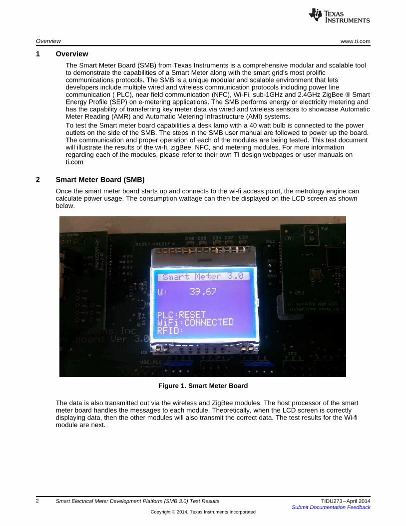
2 Smart Meter Board (SMB)Once the smart meter board starts up and connects to the wi-fi access point, the metrology engine cancalculate power usage. The consumption wattage can then be displayed on the LCD screen as shownbelow.
Figure 1. Smart Meter Board
The data is also transmitted out via the wireless and ZigBee modules. The host processor of the smartmeter board handles the messages to each module. Theoretically, when the LCD screen is correctlydisplaying data, then the other modules will also transmit the correct data. The test results for the Wi-fimodule are next.
2 Smart Electrical Meter Development Platform (SMB 3.0) Test Results TIDU273–April 2014Submit Documentation Feedback
3 Wi-fi Graphical Results AppletA graphical user interface was designed to take the information from each packet of informationtransmitted via the wi-fi module and create a graph of past metering data including a read out of thecurrent wattage. As seen below, the current reading is about 40 watts, which is correct because a 40 wattbulb is being measured by SMB.
Figure 2. Wi-Fi GUI
4 ZigBee In-Home DisplayBefore the in-home display starts receiving data from the SMB, the LCD screen will read “lhd430”. Oncethe IHD is receiving data the screen will show an antenna symbol with signal strength. The center of thedisplay will present the current metering data.
Figure 3. In-Home Display
3TIDU273–April 2014 Smart Electrical Meter Development Platform (SMB 3.0) Test ResultsSubmit Documentation Feedback
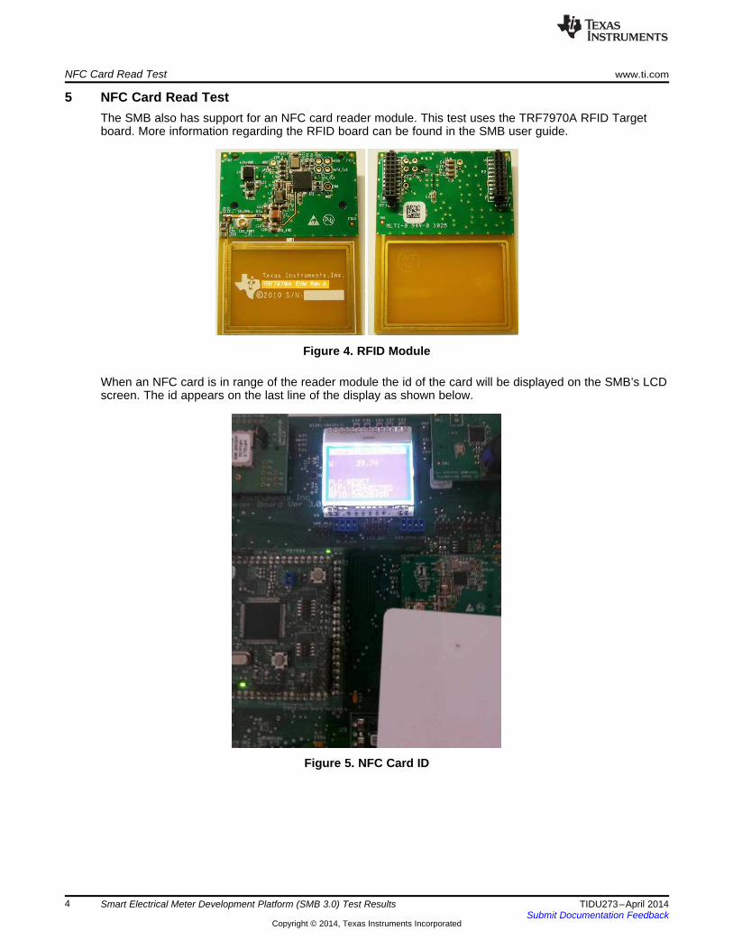
5 NFC Card Read TestThe SMB also has support for an NFC card reader module. This test uses the TRF7970A RFID Targetboard. More information regarding the RFID board can be found in the SMB user guide.
Figure 4. RFID Module
When an NFC card is in range of the reader module the id of the card will be displayed on the SMB’s LCDscreen. The id appears on the last line of the display as shown below.
Figure 5. NFC Card ID
4 Smart Electrical Meter Development Platform (SMB 3.0) Test Results TIDU273–April 2014Submit Documentation Feedback
6 Test ResultsThe test is successful. Both the SMB, wi-fi GUI and the in-home display present similar data. The IHD lagsone second behind the Smart meter board’s LCD because the IHD screen updates every second. Inconclusion, the SMB 3.0 and the in-home display both show about 40 watts when a 40 watt load isconnected to the power outlets of the SMB 3.0.
Figure 6. Test Results
5TIDU273–April 2014 Smart Electrical Meter Development Platform (SMB 3.0) Test ResultsSubmit Documentation Feedback
IMPORTANT NOTICE AND DISCLAIMERTI PROVIDES TECHNICAL AND RELIABILITY DATA (INCLUDING DATA SHEETS), DESIGN RESOURCES (INCLUDING REFERENCE DESIGNS), APPLICATION OR OTHER DESIGN ADVICE, WEB TOOLS, SAFETY INFORMATION, AND OTHER RESOURCES “AS IS” AND WITH ALL FAULTS, AND DISCLAIMS ALL WARRANTIES, EXPRESS AND IMPLIED, INCLUDING WITHOUT LIMITATION ANY IMPLIED WARRANTIES OF MERCHANTABILITY, FITNESS FOR A PARTICULAR PURPOSE OR NON-INFRINGEMENT OF THIRD PARTY INTELLECTUAL PROPERTY RIGHTS.These resources are intended for skilled developers designing with TI products. You are solely responsible for (1) selecting the appropriate TI products for your application, (2) designing, validating and testing your application, and (3) ensuring your application meets applicable standards, and any other safety, security, regulatory or other requirements.These resources are subject to change without notice. TI grants you permission to use these resources only for development of an application that uses the TI products described in the resource. Other reproduction and display of these resources is prohibited. No license is granted to any other TI intellectual property right or to any third party intellectual property right. TI disclaims responsibility for, and you will fully indemnify TI and its representatives against, any claims, damages, costs, losses, and liabilities arising out of your use of these resources.TI’s products are provided subject to TI’s Terms of Sale or other applicable terms available either on ti.com or provided in conjunction with such TI products. TI’s provision of these resources does not expand or otherwise alter TI’s applicable warranties or warranty disclaimers for TI products.TI objects to and rejects any additional or different terms you may have proposed. IMPORTANT NOTICE


![[MS-SMB-Diff]: Server Message Block (SMB) Protocol... · 2018. 9. 10. · Server Message Block (SMB)](https://static.documents.pub/doc/80x56/601e82785cca6a3942273390/ms-smb-diff-server-message-block-smb-protocol-2018-9-10-server-message.jpg)


