Smart Grid communication applications: measurement equipment and networks architecture for data and energy flow
Tinton Dwi Atmaja a, *, Dian Andriani b, Rudi Darussalam a a Research Centre for Electrical Power and Mechatronics, Indonesian Institute of Sciences
Komp LIPI Bandung, Gd 20, Lt 2, Bandung, West Java, 40135 Indonesia b Research Unit for Clean Technology, Indonesian Institute of Sciences
Komp LIPI Bandung, Gd 50, Bandung, West Java, 40135 Indonesia
Received 13 September 2019; accepted 25 November 2019
Abstract
Smart Grid is an advanced two way data and energy flow capable of self-healing, adaptive, resilient, and sustainable with prediction capability of possible fault. This article aimed to disclose Smart Grid communication in a logical way to facilitate the understanding of each component function. The study was focused on the improvement, advantages, common used design, and possible feature of Smart Grid communication components. The results of the study divide the Smart Grid communication application into two main category i.e. measurement equipment and network architecture. Measurement equipment consists of Advance Metering Infrastructure, Phasor Measurement Unit, Intelligent Electronic Devices, and Wide Area Measurement System. The network architecture is divided based on three hierarchies; local area network for 1 to 100 m with 100 kbps data rate, neighbour area network for 100 m to 10 km with 100 Mbps data rate, and wide area network for up to 100 km with 1 Gbps data rate. More information is provided regarding the routing protocol for each network from various available protocols. The final section presents the energy and data flow architecture for Smart Grid implementation based on the measurement equipment and the network suitability. This article is expected to provide a comprehensive guide and comparison surrounding the technologies supporting Smart Grid implementation especially on communication applications.
Keywords: Smart Grid application; phasor measurement unit; communication network; communication protocol; energy and data flow.
I. Introduction
Recent researches on Smart Grid have been focused on addressing readability, adaptability, and fault prediction issues [1]. Further challenges on Smart Grid research should include demand handling, service quality, grid flexibility, power sustainability, end to end full control, market enabling, cost reduction, performance optimization, self-healing, and grid restoration [2].
The increase of distributed generation (DG) penetration brings an increased number of parameters including networks constrain, thermal overload, voltage limits, and hardwire connection complexities. Communication application is the key component to provide reliable Smart Grid operation by facilitating a real-time connection for measuring,
monitoring, and controlling the grid assets [3][4][5]. Two way communications with high speed data rate in Smart Grid communication will give a dynamic infrastructure for power exchange [6][7][8].
Developing a smart communication system and subsystem requires monitoring and metering capability which covers the entire domain from the generation up to distribution [9]. Advanced metering infrastructure (AMI) can be assumed as the upgraded version of the conventional automated meter reading and automated meter management. AMI involves smart meter, communication network, and data management system [10].
Phasor measurement unit (PMU) can also be considered as the upgrade of the conventional system. Supervisory control and data acquisition (SCADA) played a significant role in the power system until the communication technology has evolved and the grid is demanding a fast unlimited data access at so many network node [11]. PMU deployment will lead to the
T. D. Atmaja et al. / Journal of Mechatronics, Electrical Power, and Vehicular Technology 10 (2019) 73-84
74
implementation of some technologies which cannot be handled properly by the conventional power delivery system, such as high-voltage direct currents (HVDCs) and intelligent electronic devices (IEDs) [11]. PMU is also able to estimate the synchrophasor, frequency, and the rate of change of frequency (ROCOF or d f/dt) of the acquired voltage and/or current waveforms [12]. The common standards used by synchrophasor technology were IEEE 1344, IRIG-B, IEEE C37.118, and IEC61850 [13][14]. PMU has been dedicated as the most effective measurement device for monitoring, control, and protection of the evolved power system in correspondence to its capability on addressing technological update and covering the geographical extension of the modern power system [15].
Communication network should be the next focus after the measurement system. Smart Grid network should be classified in the typical payload, data sampling, latency, and reliability [16]. This study has divided the communication network basically by its data rate and coverage area [3][17]. Routing development of each network classification had been explained to describe the interaction of each component in a proper way with respect to the various Smart Grid applications. The connection protocols have been categorized on the existing approach for local area network, neighbor area network, and wide area network. Furthermore, open architecture with plug and play features should provide a better environment for smart sensor and control devices.
This article aimed to disclose Smart Grid communication components to facilitate the understanding of the further function of each component. The result of the study provides a detail explanation of the technologies’ features, advantages, connectivity, and primary role in supporting Smart Grid implementation, especially on Smart Grid communication.
II. Materials and Methods
The article focused on the Smart Grid communication components by presenting their improvement, advantages, commonly used design,
and possible feature. The Smart Grid communication application is divided into its measurement equipment and network architecture. The measurement equipment consists of Advance Metering Infrastructure, Phasor Measurement Unit, and Intelligent Electronic Devices. Meanwhile, the network architecture is divided based on their hierarchy; namely local area network, neighbor area network, and wide area network. Further information was provided regarding the routing protocol for each network. The final section was presenting the energy and data flow of Smart Grid implementation based on the communication application.
III. Smart Grid Communication Equipment
A. Advanced metering infrastructure
The advanced metering infrastructure consists of several components which provide two way intelligent links from the consumers to the system management [18][19][20]. The infrastructures commonly consist of three segments; namely the consumer data collection devices, the system management, and a communication network as the connector. Figure 1 shows the schematic representation of AMI [2][21]. The implementation of AMI is the first step to upgrade the conventional grid into the modern Smart Grid. It requires telecommunication system, wiring component, various standard, and numerous best practices. All the digitalized asset on the consumers will provide information for the system management to make an intelligent decision on the grid real-time condition. Digitalize asset all over the grid will enhance the service that lead to significant benefit for the customer and the management. Various supporting technology such as smart metering, HAN, utility application, etc. will enhance the two-way interactions among utilities, consumer, and the network.
Basically, AMI acts as the main backbone for the information flow between the consumer and the utility grid. The infrastructure will monitor and control the power generation system, the storage
Data Collection and Analysis
AMI hostManagement
System
End User data collection
Communication network
Data Management
Electric meter Gas meter Water meter
Data Transmisison
Network
Data Storage
WAN
NAN/FAN
HAN/BAN/IAN
Figure 1. AMI implementation schematic
T. D. Atmaja et al. / Journal of Mechatronics, Electrical Power, and Vehicular Technology 10 (2019) 73-84
75
units, data reception equipment, and perform a possible big data analysis. At the end user, smart metering devices can be combined with the power quality monitoring system to fasten the smart demand response for any power quality troubleshoots. Within the correct range, remote connection and disconnection is considered as a possible implementation to minimize on-field personnel and reduce the operational cost. This infrastructure was also implemented not only for data storage but also as a back up strategy for possible attack or anomaly. It can be equipped with forecasting neural network to detect possible failure followed with self-healing capability performed from data management center. AMI collected data provides granularity and timeliness information to improve asset management and operations. Figure 2 shows AMI feature presented on each side of the domain [21].
1) AMI subsystem
AMI assist the consumer portal layer to connect entirely with metering layer and also with the communication layer. All smart metering devices in the HAN and LAN will be connected and controlled in a very intelligent step toward modern power grid. AMI technology and interference is shown in Figure 3 [21]. The infrastructure covers the communication
network, smart metering devices, HAN-LAN, gateways, local data concentrators, data center, and meter data management system. The final function of AMI is to add the collected data into big data platforms.
2) AMI communication technologies
Several communication technologies is available
in the today’s market such as long term evolution
(LTE), LTE-Advanced, power line carrier (PLC), general packet radio service (GPRS), 802.22 wireless networking protocol, and Zigbee. Table 1 shows a comparison of some available communication technologies in correspondence with AMI requirement [2]. Although the comparison shows many advantages of LTE application, the utility companies still consider the cost and the spectrum as the main reason of not using the LTE. More modifications are encouraged to be implemented in the communication technology such as open standard on utility communication which can be lead to a better connection between communication systems.
B. Phasor measurement units
PMU is employing a general time source to measure the electrical wave on the utility grid [22][23][24]. PMU basic component consists of the
Figure 2. AMI features in each Smart Grid communication domain
Consumer side
•Consumption data collection
•Power loss
•Time-based pricing
•Net metering
•Power restoration
•Power quality monitoring
•Remote turn on/off operations
•Prepaid eletrification
•Energy tamper detection
•Load limitation
•Communications with other intelligent devices
•GOAL: Intelligent energy consumption decisions
Utility side
•AMI data collection
•AMI data analyzing
•Optimizing economics
•Operations and consumer service
•Instant feedback
•Notifying consumer outages
•Address utility grid deficiencies
•Utility grid automation
•Planning of asset maintenance
•Assest addition or replacement
•Goal: reliable and efficient utility grid operation
Communication network
•Facilitating various equipment:
•Power line carrier
•Copper
•Optical fiber
•Internet, or
•Wireless point
•Continuous interaction between the consumer and the utility
•Ranged data collection and communication
•Act as local concentrators for data gathering
•Goal: optimum data transmission from user to central server
Figure 3. AMI subsystem technology and interferences
Consumer portal layer
Metering layer
Communication layer
Home area network
DER
Smart meter
Local area network
Smart meter
DER
Local control device
Local control device
DMS
DMS gateway
Communication
AMI board end
MDMS
DMS gateway
Consumer service
T. D. Atmaja et al. / Journal of Mechatronics, Electrical Power, and Vehicular Technology 10 (2019) 73-84
76
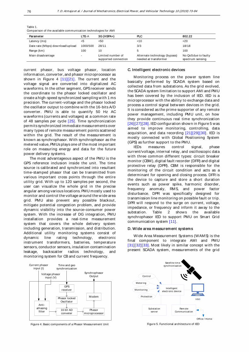
current phasor, bus voltage phasor, location information, converter, and phasor microprocessor as shown in Figure 4 [11][21]. The current and the voltage signal are converted into digitalized AC waveforms. In the other segment, GPS receiver sends the coordinate to the phasor locked oscillator and create a high-speed synchronized sampling with 1 ms precision. The current-voltage and the phasor locked the oscillator output to combine with the 16-bits A/D converter. PMU is able to quantify 50 Hz AC waveforms (currents and voltages) at a common rate of 48 samples per cycle [25]. Time synchronization permits synchronized immediate measurements over many types of remote measurement points scattered within the grid. The result of the measurement is known as synchrophasor. With synchrophasor as the metered value, PMUs plays one of the most important role on measuring energy and data for the future power delivery systems.
The most advantageous aspect of the PMU is the GPS reference inclusion inside the unit. The time source is calibrated and synchronized into resultant time-stamped phasor that can be transmitted from various important cross points through the entire utility grid. With up to 120 samples per second, the user can visualize the whole grid in the precise angular among various locations. PMU mostly used to monitor and control the voltage around the wide area grid. PMU also prevent any possible blackout, mitigate potential congestion problem, and provide dynamic visibility into the source-consumer power system. With the increase of DG integration, PMU installation provides a real-time measurement system that covers the whole delivery system including generation, transmission, and distribution. Additional utility monitoring systems consist of dynamic line rating technology, electronic instrument transformers, batteries, temperature sensors, conductor sensors, insulation contamination leakage, backscatter radios technology, and monitoring system for CB and current frequency.
C. Intelligent electronic devices
Monitoring process on the power system line basically performed by SCADA system based on collected data from substations. As the grid evolved, the SCADA system limitation to support AMI and PMU has been covered by the inclusion of IED. IED is a microprocessor with the ability to exchange data and process a control signal between devices in the grid. It is considered as the prime supporter of any remote power management, including PMU unit, on how they provide continuous real time synchronization [26][27][28]. IED configuration shown in Figure 5 was aimed to improve monitoring, controlling, data acquisition, and data recording [21][29][30]. IED is mostly connected with Global Positioning System (GPS) as further support to the PMU.
IEDs measures control signal, phase current/voltage, internal relay, and oscilloscopic data with three common different types: circuit breaker monitor (CBM), digital fault recorder (DFR) and digital protective relay (DPR). CBM is responsible for the monitoring of the circuit condition and acts as a determinant for opening and closing process. DFR is the device to capture and store a short duration events such as power spike, harmonic disorder, frequency anomaly, RMS, and power factor disturbance. DPR was specifically designed for transmission line monitoring on possible fault or trip. DPR will respond to the surge on current, voltage, impedance, or frequency and inform it away to the substation. Table 2 shows the available synchrophasor IED to support PMU on Smart Grid communication system [11].
D. Wide area measurement systems
Wide Area Measurement Systems (WAMS) is the final component to integrate AMI and PMU [31][32][33]. Most likely in similar concept with the present SCADA system, measurements of the grid
Table 1.
Comparison of the available communication technologies for AMI
Parameter LTE-A 3G (HSPA+) PLC 802.22
Latency (ms) <5 <50 <10 <20
Date rate (Mbps) download/upload 1000/500 28/11 3/3 18/18
Range (km) 100 10 5 100
Main disadvantage - Limited number of supported connection
Alternate technology (bypass) needed at transformer
No QoS due to faulty spectrum sensing
Figure 4. Basic components of a Phasor Measurement Unit
GPS receiver
Phasor locked Oscillator
16 bit AD conveter
Phasor microprocessor
Modem
Anti-alliasing
filter
Synchrophasor Output
Voltage phasor input (V)
Current phasor input (I)
Time and geo synchronization
Remote Communication
Substation server
Protection
Monitoring
Metering
Control
HMI
Office / Home
Intelligent electronic device
Satellite timesynchronisation
Figure 5. Functional architecture of IED
T. D. Atmaja et al. / Journal of Mechatronics, Electrical Power, and Vehicular Technology 10 (2019) 73-84
77
system are conceded at a higher rate (up to 5-60 samples per second). Therefore, the system requires a wide area measurement which can perform continuous and simultaneous real-time information rendering [34][35]. More or less, WAMS was aiming to improve the grid performance by stability
assessment, fault detection, remedial control actions and supporting more accurate state estimation [36][37].
Figure 6 shows the common WAMS architecture which deploys PMUs, PDCs, super PDCs (regional PDCs), and communication protocol [11]. PMU send
Table 2.
Commercial syncrophasor-based IEDs
Company IED Application
ABB PVI-PMU (power
management unit)
Photovoltaic system monitoring, active and reactive power control
RES670 2.0 (relion 670 & 650 series)
Power system protection and control
PSGuard SCADA/EMS integration and communication, power system monitoring
General Electric,
grid solutions
MiCOM P40 Agile Feeder management
EATON GearGard Conditional remote monitoring and early failure warning solutions Real-time monitoring, statistical analysis, and condition-based maintenance
decisions
Mehta Tec Data fault recorder (DFR)/disturbance
monitoring equipment (DME)/PMU
Online disturbance monitoring and data archiving
Macrodyne 1690 Phasor measurement systems for real-time data acquisition and control
1692 Integrated recording units for transient fault and long-term disturbance events
1698, 1698E Satellite timing units for absolute time tagging and synchronous data sampling
Schweitzer Engineering Laboratories (SEL)
SEL-2411 Programmable automation controller
SEL-T400L Line protection with simple configuration, accurate fault locating, and high-resolution oscillography
SEL-411L Line current di erential, distance, and directional overcurrent protection,
comprehensive monitoring, advanced automation and communication, high-accuracy fault locating
S&C electric company 6800 series Control and manage distribution switches automatically
Power Standards Lab (PSL)
PQube (PMU) Cyber-attacks detection, power consumption analysis, remotely understand commercial AC power grids, provide input for solar PV and storage control system development, simulation and data integration for solar planning tools, and short-term planning and operations
Siemens SIGUARD PDP (phasor data processor)
Complete portfolio for network monitoring, power quality recording, fault recording, phasor measurement, and system software applications
T. D. Atmaja et al. / Journal of Mechatronics, Electrical Power, and Vehicular Technology 10 (2019) 73-84
78
voltage and current in phasor form to the local phase data concentrators (PDC) using IEEE C37.118.2 or IEC 61850-90-5 standards. PDC normally located in the primary substation where the collected data was analyzed [38]. PDCs are required to make a decision with a very low latency of 10– 100 ms. IED has shown to take an important part in this WAMS by integrating devices such as reclosers, switches, and capacitor banks so that PDCs or super PDCs will be able to protect and control the grid at the distribution or transmission level immediately [39]. Future concept can use IEC61850-90-5 to replace IEEE C37.118.2 protocol [40].
IV. Smart Grid Communication Networks
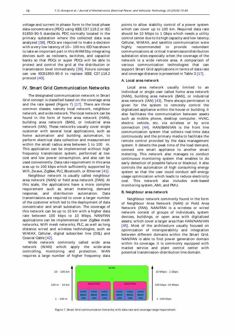
The designated communication network in Smart Grid concept is classified based on the coverage area and the rate speed (Figure 7) [17]. There are three common classes; namely local network, neighbour network, and wide network. The local network can be found in the form of home area network (HAN), building area network (BAN), or industrial area network (IAN). These networks usually cover single customer with several local applications, such as home automation and building automation, to perform electrical data collection and measurement within the small radius area between 1 to 100 m. This application can be implemented without high frequency transmission system, performed at low cost and low power consumption, and also can be used conveniently. Data rate requirement in this area was up to 100 kbps which sufficiently supported by Wifi, Zwave, ZigBee, PLC, Bluetooth, or Ethernet [41].
Neighbour network is usually called neighbour area network (NAN) or field area network (FAN). At this scale, the applications have a more complex requirement such as smart metering, demand response, and distribution automation. Data transmissions are required to cover a larger number of the customer which led to the deployment of data concentrator and small substation. The coverage of this network can be up to 10 km with a higher data rate between 100 kbps to 10 Mbps. NAN/FAN applications can be implemented over ZigBee mesh networks, WiFi mesh networks, PLC, as well as long distance wired and wireless technologies, such as WiMAX, Cellular, digital subscriber line (DSL) and Coaxial Cable [42].
Wide network commonly called wide area network (WAN) which apply the wide-area controlling, monitoring and protection. WAN requires a large number of higher frequency data
points to allow stability control of a power system which can cover up to 100 km. Required data rate should be 10 Mbps to 1 Gbps which needs a utility control center due to its high capacity and low latency. Cellular, WiMAX, and satellite communication were highly recommended to provide redundant communications at critical transmission/distribution substation sites especially when the coverage of the network is a wide remote area. A comparison of various communication technologies that can support Smart Grid applications in terms of data rate and coverage distance is presented in Table 3 [17].
A. Local area network
Local area network usually limited to an individual or single user called home area network (HAN), building area network (BAN), or industrial area network (IAN) [43]. There always permission is given for the system to remotely control the digitalized appliance within the house or building. It also facilitates the communication between assets such as mobile phone, desktop computer, HVAC, electric vehicle, etc. via wireless or by wire connection [44]. HAN/BAN/IAN is the front line communication system that collects real-time data continuously and the primary media to facilitate the remote control provided by the data management system. It detects the peak time of the load demand, connect one smart appliance to another smart metering. This network also manages to conduct continuous monitoring system that enables to do early detection of possible failure or blackout. It also controls the automation of high consuming energy system so that the user could conduct self-energy usage optimization which leads to reduce electricity cost. This network also includes web-based monitoring system, AMI, and PMU.
B. Neighbour area network
Neighbour network commonly found in the form of Neighbour Area Network (NAN) or Field Area Network (FAN). NAN/FAN is a wireless or wired network consist of groups of individuals, system devices, buildings, or open area with digitalized assets; which cover a larger area than HAN/NAN/IAN [45]. Most of the architecture usually focused on optimization of interoperability and integration between different domains within the Smart Grid. NAN/FAN is able to find power generation domain within its coverage, it is commonly equipped with market service and plant control center with potential transmission-distribution line domain.
Figure 7. Smart Grid communication hierarchy with data rate and coverage range requirement
WAN
NAN/FAN
HAN/BAN/IAN 1 -100 kbps
100 kbps -10 Mbps
10 Mbps – 1 Gbps
1 – 100 m
100 m – 10 km
10 – 100 km
HAN/BAN/IAN
HAN/BAN/IAN
NAN/FAN
HAN/BAN/IAN
HAN/BAN/IAN
HAN/BAN/IAN
T. D. Atmaja et al. / Journal of Mechatronics, Electrical Power, and Vehicular Technology 10 (2019) 73-84
79
NAN/FAN is also considered as a substation connecting the local network with the wide network. It means that this network has quite large data storage to facilitate a large data collection system form the HAN/BAN/IAN. The neighbour network will connect many energy management systems, digitalized appliances, metering devices, more electric storages, and even consumer PHEVs. The connection to the consumer will primarily through the internet with the possible use of the large intranet. Depend on the area coverage, this network can be subdivided into transmission-distribution system using ISO/RTO technology. Therefore, this network is able to handle the utility of third party including billing system and larger early warning system.
C. Wide area networks (WAN)
WAN is the largest geographical coverage network compared to local or neighbour network, it usually interconnects multiple BAN/HAN/IAN or NAN/FAN [46]. WAN is commonly in the shape of point-to-point technology (PP), circuit-switched technology (CS), or packet-switched technology (PS). PP is a costly technology and usually in the form of the leased or dedicated line which is attached to the utility backbone and provided a secure line between the local domain. It usually on the state of normally-ON to ensure continuous line between network nodes on specified distance. CS technology needs a call-setup to make an action on the grid. Once the call has made, the data transfer will trigger the session and followed by engaging or disengaging a single or
multiple domains. On-demand switched is usually a low speed response compared with the other technologies. The last technology is packet-switched which is the cheapest of all technologies due to it share a common infrastructure. Despite having the best performance in communication quality, however, it will cause inconsistent bandwidth.
V. Smart Grid Communication Routing Protocol
The goal of routing protocol is the reliability, security and QoS of the network performance [3][47][48]. The protocol has been classified into three classes i.e. routing for local network (HAN/BAN/IAN), routing for neighbour network (NAN/FAN), and routing for wide network (WAN). The breakdown of the routing protocol for each class can be found in Figure 8 [3].
A. Routing protocols for local network
Summary of routing protocols for the local network (HAN/BAN/IAN) can be found in Table 4 based on the adaptation layer and network layer [3]. The use of a specific protocol will affect the operational cost, performance of the network and the local network architecture.
B. Routing protocols for neighbour network
Smart Grid communications consist of several NAN/FAN with mostly hundreds of AMI. NAN routing protocol will ensure the collected data from the
Table 3. Comparison of communication technologies for the Smart Grid
Technologies Standard/ protocol
Theoretical data rate
Coverage range
Network
HAN/BAN/IAN NAN/FAN WAN
Wired communication technologies
Coaxial Cable DOCSIS 172 Mbps Up to 28 km
Ethernet 802.3x 10 Mbps - 10 Gbps Up to 100 m x x
PLC Homeplug 14–200 Mbps Up to 200 m x
Narrowband 10–500 kbps Up to 3 km x
DSL ADSL 1–8 Mbps Up to 5 km
HDSL 2 Mbps Up to 3.6 km x
VDSL 15–100 Mbps Up to 1.5 km
Fiber optic PON 155 Mbps–2.5 Gbps Up to 60 km x
WDM 40 Gbps Up to 100 km
SONET/SDH 10 Gbps Up to 100 km x
Wireless communication technologies
Z-Wave Z-Wave 40 kbps Up to 30 m x
Bluetooth 802.15.1 721 kbps Up to 100 m x
ZigBee ZigBee 250 kbps Up to 100 m x x
ZigBee Pro 250 kbps Up to 1600 m
WIFI 802.11x 2–600 Mbps Up to 100 m
WiMAX 802.16 75 Mbps Up to 50 km
Wireless Mesh Various (e.g., RF mesh, 802.11, 802.15, 802.16)
Depending on selected protocols
Depending on deployment
x x
Cellular 2G 14.4 kbps up to 50 Km x x
2.5G 144 kbps
3G 2 Mbps
3.5G 14 Mbps
4G 100 Mbps
Satellite Satellite Internet 1 Mbps 100 - 6000 Km x
T. D. Atmaja et al. / Journal of Mechatronics, Electrical Power, and Vehicular Technology 10 (2019) 73-84
80
access point tier can report safely to the backhaul distribution tier. Routing challenge will vary based on the underlying communication. Therefore, there are three common protocols: Reliable Routing [49][50], Secure Routing [51][52][53], and QoS Routing protocols [54]. The comparison of each routing protocols can be seen in Table 5 [3].
C. Routing Protocols for Wide Network
Wide Network is different from local and neighbour network since it most likely consists of a core network or a backhaul network. Generally, WAN routing protocol is handled by the public network such as the internet and private lines. Fiber optic is the best offer to the required data rate and should be
Figure 8. Routing protocol classification for Smart Grid communications
Table 4. Summary of routing protocols for local network
Routing protocol Adaptation layer Data link Network layer
ZigBee n/a CSMA/CA Tree routing, on-demand mesh routing, source routing
Mesh under Layer 2 mesh routing CSMA/CA n/a
Route over n/a CSMA/CA RPL routing
Wireless-HART n/a TDMA Graph and source routing
ISA100.11a n/a TDMA, CSMA/CA, graph routing and source routing
Backbone routing
Z-Wave n/a CSMA/CA Source routing
INSTEON n/a TDMA Simulcast
Table 5. Routing protocol classification for NANs
Routing protocol Point-to-
point routing
One-to many
routing
Many-to-
one routing
Multipath Scalable Load balancing
Application
DADR √ √ √ √ √ Wireless AMI
Hydro √ √ √ √ √ √ Wireless AMI
Timer based multipath diversity routing
√ √ √ Wireless AMI, status management and monitoring
- IP/MPLS - Internet / Private line - Wi-Max- 4G- GPRS
Reliable Routing NANs
T. D. Atmaja et al. / Journal of Mechatronics, Electrical Power, and Vehicular Technology 10 (2019) 73-84
81
followed by IP/multi-protocol label switching (MPLS) and Metro Ethernet. Another option is to apply Wi-MAC, 4G, or GPRS even though they depend on the quality of the physical layer, channels, radio, handoff, etc. The newest study showed that the deployment of multi-hop wireless WAN can be a proprietary network within a single instalment which have a complete substation, gateway, and data metering devices.
VI. Smart Grid Data and Energy Flow Architecture
The energy flow has been completely covered by the conventional utility grid. Nevertheless, the challenge on the Smart Grid implementation is covering the data flow within the entire grid. The first challenge is the digitalization of all the grid asset in order to be able to reach out the communication protocols. Combination of energy flow and data flow will then increase the controllability, flexibility, and more adaptive response. The data and energy flow should be covering all the domain including power
generation, transmission-distribution, and customers’
peripheral. Figure 9 shows the architecture of data and energy flow in Smart Grid with a wide multi-port system network node [21][55].
The architecture presented in Figure 9 covers the measurement equipment AMI and PMU, and consisting of three layers communication network. Local network mostly exists in the customer side which facilitates the control and monitoring of all digitalized appliances. Local network also connects
the AMI to the energy management system (EMS), energy storage system (ESS), and possible use of plug-in hybrid electric vehicle (PHEV). The connection with PHEV would introduce the concept of vehicle to grid (V2G) where the charge and discharge action will depend completely on the time and location. Neighbour network would be consisting of at least two local networks, therefore, consisting of several AMI and possible local DG. AMIs in the customer side
had connected to the substation’s PMU in the
distribution line, while each substation’s PMU will
connect each other in the transmission line. Moreover, the transmission line is the backbone network which unites the power generation side to the customer side. Power generation could be a large scale power plant in a remote location or could be small size DG within local neigbourhood. Each power plant would have its own substation, or multiple power plants covered by
one substation. Substations’ PMU at the power
generation side will be connected to the backbone and coordinate with the PMUs at the consumer side.
These measurement devices and multi layers network contains different component with various characteristics and action. For example, DGs and load can connect or disconnect at any time without proper pattern. Therefore Smart Grid data management center must play the role of multi-agent to ensure that every node can be controlled in a specific manner. Every information provided by the AMIs and PMUs will be processed at the center and provide a control
output to each of grid’s digitalize asset. Farsighted
the large number of AMIs and PMUs, it is
Figure 9. Data and energy flow architecture in Smart Grid
Power GenerationTransmission and DistributionCustomer
NA
N/F
AN
HA
N/B
AN
/IAN
WA
NESS
AMI
PMUPHEV
EMS
Energy flow
Data flow
ESS
AMI PMU
PHEV
EMS
Substation
Substation
PMU
PMU
Substation
PMU
PMU
PMU
PMU
Substation
Data Management Center
T. D. Atmaja et al. / Journal of Mechatronics, Electrical Power, and Vehicular Technology 10 (2019) 73-84
82
recommended to adapt the cloud computing architecture to cover all the big data at the grid.
Cloud computing has served as an excellent method to handle a large volume of data in the coverage of all AMI and PMU [56][57]. Cloud computing can provide flexibility and scalable characteristic to cope with the data storage and vast transferable real-time data [58][59][60]. With the expanding area of the Smart Grid, cloud computing can easily adapt to present remote data storage, automatic updates, less utility cost, energy saving, and reduce human labor demand [61][62][63]. Cloud computing architecture for Smart Grid designed by Dileep G. [21] can be found in Figure 10.
This architecture can be adapted to create a cloud database which stores public and private information. Each information class can be managed as three basic cloud services i.e. Data as a service (DaaS), software as a service (SaaS), and infrastructure as a service (IaaS). The analytic can perform energy analysis within the
grid, reporting and monitoring the grid’s asset, and
the most important is the visualization of the grid.
VII. Conclusion
This article presents an overview of the one key component of Smart Grid, the communication application including the related technologies. The study was done by conducting a review of its components, technologies, features, challenge, and advantages. It is known that efficiency, reliability, and security of interconnected devices are critical to enabling Smart Grid global implementation. The study explained various Smart Grid measurement technologies such as AMI, PMU, IED, and WAMS followed by the description of Smart Grid network classification divided in three classes i.e. HAN/BAN/IAN, NAN/FAN, and WAN. The AMI and PMU were covering the measurement system and data collection while the IED and WAMS was covering the secure and reliable data transfer from the consumer to the data management center.
HAN/BAN/IAN is a local network which facilitates Smart Grid from the end user platform at low 100 kbps data rate for the least 1 to 100 m, while NAN/FAN is doing the similar task at the larger coverage area which is up to 10 km for 10 Mbps data rate. For the last, WAN is the one covering the whole local and neighbour network by approximately 100 km at 1 Gbps data rate. Related technologies are including routing protocol for each network that considers the underlying communications medium, reliability, security, and QoS. The primary function is to facilitate the measurement and monitoring process and then collect the data for the grid analysis at the data management center. This communication network will increase the flexibility to the attachment of DGs which will increase the usage of renewable energy. Smart Grid can be considered as a future technology to help environmental conservation and energy sustainability. It is expected that this article can offer a further understanding of communication network requirements for a complete Smart Grid implementation.
Acknowledgement
The author would like to thank all researchers at Research Centre for Electrical Power and Mechatronics and Research Unit for Clean Technology, Indonesian Institute of Science for the completion of this study.
Declarations
Author contribution
All authors contributed equally as the main contributor of this paper. All authors read and approved the final paper.
Funding statement
This research did not receive any specific grant from funding agencies in the public, commercial, or not-for-profit sectors.
Figure 10. Smart Grid cloud architecture
Web portal access
Analytics- Energy analysis- Reporting/analytics- Visualization
Daas- Data management/aggregation- Data optimization
Saas- Geospatial- Wheather prediction
IaaS- Storage- Web hosting- Network performance monitoring- DR/backup- High performance computing- Authentication and accreditation
Services
Data
Utilities- Energy production- energy management- Asset management- Metering information- Remote power quality monitoring
Consumers
Bi-directional energy flow
Sensing and measuring
Private cloud
Public cloud
Firewall
T. D. Atmaja et al. / Journal of Mechatronics, Electrical Power, and Vehicular Technology 10 (2019) 73-84
83
Conflict of interest
The authors declare no conflict of interest.
Additional information
No additional information is available for this paper.
References
[1] J. A. Momoh, “Smart grid design for efficient and flexible power
networks operation and control,” in 2009 IEEE/PES Power Systems Conference and Exposition, 2009, pp. 1–8.
[2] R. Rashed Mohassel, A. Fung, F. Mohammadi, and K. Raahemifar,
“A survey on Advanced Metering Infrastructure,” Int. J. Electr. Power Energy Syst., vol. 63, pp. 473–484, Dec. 2014.
[3] N. Saputro, K. Akkaya, and S. Uludag, “A survey of routing
protocols for smart grid communications,” Comput. Networks,
vol. 56, no. 11, pp. 2742–2771, Jul. 2012.
[4] M. Erol-Kantarci and H. T. Mouftah, “Energy-Efficient
Information and Communication Infrastructures in the Smart
Grid: A Survey on Interactions and Open Issues,” IEEE Commun. Surv. Tutorials, vol. 17, no. 1, pp. 179–197, 2015.
[5] E. Ancillotti, R. Bruno, and M. Conti, “The role of communication
systems in smart grids: Architectures, technical solutions and
research challenges,” Comput. Commun., vol. 36, no. 17–18, pp.
1665–1697, Nov. 2013.
[6] J. Naus, G. Spaargaren, B. J. M. van Vliet, and H. M. van der Horst,
“Smart grids, information flows and emerging domestic energy
practices,” Energy Policy, vol. 68, pp. 436–446, May 2014.
[7] J. Gao, Y. Xiao, J. Liu, W. Liang, and C. L. P. Chen, “A survey of
communication/networking in Smart Grids,” Futur. Gener. Comput. Syst., vol. 28, no. 2, pp. 391–404, Feb. 2012.
[8] N. Kilic and V. C. Gungor, “Analysis of low power wireless links
in smart grid environments,” Comput. Networks, vol. 57, no. 5,
pp. 1192–1203, Apr. 2013.
[9] S. Bruno, S. Lamonaca, M. La Scala, G. Rotondo, and U. Stecchi,
“Improving Energy Efficiency in a Power Park by the Integration
of a Hydrogen Steam Reformer,” in 2009 Asia-Pacific Power and Energy Engineering Conference, 2009, pp. 1–8.
[10] S. Paul, M. S. Rabbani, R. K. Kundu, and S. M. R. Zaman, “A review
of smart technology (Smart Grid) and its features,” in 2014 1st International Conference on Non Conventional Energy (ICONCE 2014), 2014, pp. 200–203.
[11] M. Hojabri, U. Dersch, A. Papaemmanouil, and P. Bosshart, “A
Comprehensive Survey on Phasor Measurement Unit
Applications in Distribution Systems,” Energies, vol. 12, no. 23,
p. 4552, Nov. 2019. [12] I. Power and E. Society, C37.118.1-2011 - IEEE Standard for
Synchrophasor Measurements for Power Systems, vol. 2011, no.
December. 2011.
[13] K. E. Martin et al., “Exploring the IEEE standard C37.118-2005
synchrophasors for power systems,” IEEE Trans. Power Deliv., 2008.
[14] V. Vyatkin, G. Zhabelova, N. Higgins, K. Schwarz, and N.-K. C.
Nair, “Towards intelligent Smart Grid devices with IEC 61850
Interoperability and IEC 61499 open control architecture,” in
IEEE PES T&D 2010, 2010, pp. 1–8.
[15] D. K. Mohanta, C. Murthy, and D. Sinha Roy, “A Brief Review of
Phasor Measurement Units as Sensors for Smart Grid,” Electr. Power Components Syst., vol. 44, no. 4, pp. 411–425, Feb. 2016.
[16] M. Jarrah, M. Jaradat, Y. Jararweh, M. Al-Ayyoub, and A.
Bousselham, “A hierarchical optimization model for energy
data flow in smart grid power systems,” Inf. Syst., vol. 53, pp.
190–200, Oct. 2015.
[17] M. Kuzlu, M. Pipattanasomporn, and S. Rahman,
“Communication network requirements for major smart grid
applications in HAN, NAN and WAN,” Comput. Networks, vol.
67, pp. 74–88, Jul. 2014.
[18] I.-K. Yang, N.-J. Jung, and Y.-I. Kim, “Status of Advanced
Metering Infrastructure development in Korea,” in 2009 Transmission & Distribution Conference & Exposition: Asia and Pacific, 2009, pp. 1–3.
[19] G. López, J. I. Moreno, H. Amarís, and F. Salazar, “Paving the road
toward Smart Grids through large-scale advanced metering
infrastructures,” Electr. Power Syst. Res., vol. 120, pp. 194–205,
Mar. 2015.
[20] D. Wang, Z. Tao, J. Zhang, and A. A. Abouzeid, “RPL Based
Routing for Advanced Metering Infrastructure in Smart Grid,”
in 2010 IEEE International Conference on Communications Workshops, 2010, pp. 1–6.
[21] G. Dileep, “A survey on smart grid technologies and
applications,” Renew. Energy, vol. 146, pp. 2589–2625,
available online 23 August 2010.
[22] A. Ahmadi, Y. Alinejad-Beromi, and M. Moradi, “Optimal PMU
placement for power system observability using binary particle swarm optimization and considering measurement
redundancy,” Expert Syst. Appl., vol. 38, no. 6, pp. 7263–7269,
Jun. 2011. [23] F. Aminifar, A. Khodaei, M. Fotuhi-Firuzabad, and M.
Shahidehpour, “Contingency-Constrained PMU Placement in
Power Networks,” IEEE Trans. Power Syst., vol. 25, no. 1, pp.
516–523, Feb. 2010.
[24] D. J. Brueni and L. S. Heath, “The PMU Placement Problem,”
SIAM J. Discret. Math., vol. 19, no. 3, pp. 744–761, Jan. 2005.
[25] S. Das, D. Ghosh, T. Ghose, and D. K. Mohanta, “Simulation of
wide area measurement system with optimal phasor
measurement unit location,” in 2014 International Conference on Signal Processing and Integrated Networks (SPIN), 2014, pp.
226–230.
[26] I.-H. Lim and T. S. Sidhu, “Design of a Backup IED for IEC 61850-
Based Substation,” IEEE Trans. Power Deliv., vol. 28, no. 4, pp.
2048–2055, Oct. 2013.
[27] L. Zhu, D. Shi, and X. Duan, “Standard Function Blocks for
Flexible IED in IEC 61850-Based Substation Automation,” IEEE Trans. Power Deliv., vol. 26, no. 2, pp. 1101–1110, Apr. 2011.
[28] U. C. Netto, D. de Castro Grillo, I. D. Lonel, E. L. Pellini, and D. V.
Coury, “An ANN based forecast for IED network management
using the IEC61850 standard,” Electr. Power Syst. Res., vol. 130,
pp. 148–155, Jan. 2016.
[29] I.-H. Lim and T. S. Sidhu, “A new local backup scheme
considering simultaneous faults of protection IEDs in an IEC
61850-based substation,” Int. J. Electr. Power Energy Syst., vol.


![[Smart Grid Market Research] Smart Grid Hiring Trends Study (Part 2 of 2)- Zpryme Smart Grid Insights](https://static.documents.pub/doc/80x56/5414021c8d7f7284698b47a9/smart-grid-market-research-smart-grid-hiring-trends-study-part-2-of-2-zpryme-smart-grid-insights.jpg)


![[Smart Grid Market Research] The Optimized Grid - Zpryme Smart Grid Insights](https://static.documents.pub/doc/80x56/541402188d7f7294698b47d2/smart-grid-market-research-the-optimized-grid-zpryme-smart-grid-insights.jpg)


