136
Topic 3: Smart Grid Communications A.H. Mohsenian‐Rad (U of T) 1 Networking and Distributed Systems Department of Electrical & Computer Engineering Texas Tech University Spring 2012

Topic 3: Smart Grid Communications
A.H. Mohsenian‐Rad (U of T) 1Networking and Distributed Systems
Department of Electrical & Computer EngineeringTexas Tech University
Spring 2012

NIST Conceptual Reference Model for Smart Grid
Dr. Hamed Mohsenian-Rad Texas Tech UniversityCommunications and Control in Smart Grid 2
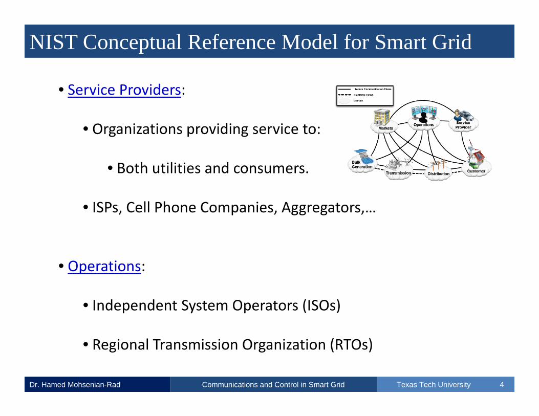
• Each domain involves its own actors and applications.
• Interactions across 7 Smart Grid Domains:

NIST Conceptual Reference Model for Smart Grid
Dr. Hamed Mohsenian-Rad Texas Tech UniversityCommunications and Control in Smart Grid 3
• Consumers:
• The end users of electricity.
• May also generate/store electricity.
• Traditionally: Residential, Commercial, and Industrial.
• Market:
• Participants in wholesale market: day‐ahead, hour‐ahead,...
• Involves prediction, bidding, auctions, …
NIST Conceptual Reference Model for Smart Grid
Dr. Hamed Mohsenian-Rad Texas Tech UniversityCommunications and Control in Smart Grid 4
• Service Providers:
• Organizations providing service to:
• Both utilities and consumers.
• ISPs, Cell Phone Companies, Aggregators,…
• Operations:
• Independent System Operators (ISOs)
• Regional Transmission Organization (RTOs)

NIST Conceptual Reference Model for Smart Grid
Dr. Hamed Mohsenian-Rad Texas Tech UniversityCommunications and Control in Smart Grid 5
• Bulk Generation:
• Major Power Plants.
• Transmission:
• Carriers of bulk electricity over long distances.
• Distribution:
• Distribution of electricity to (and from!) consumers.

NIST Model for Smart Grid Information Network
Dr. Hamed Mohsenian-Rad Texas Tech UniversityCommunications and Control in Smart Grid 6
MDMS: M
eter Data Managem
ent S
ystem,
CIS: Customer In
form
ation System
EMS: Ene
rgy Managem
ent S
ystem

Smart Grid Communications
Dr. Hamed Mohsenian-Rad Texas Tech UniversityCommunications and Control in Smart Grid 7
• There are two questions to answer:
• How can different smart grid entities exchange messages?
• What kind of messages (and why) should they exchange?
• Our focus in Topic 3 is on the first question.
• We want to learn which communication technologies may help.

Smart Grid Communications
Dr. Hamed Mohsenian-Rad Texas Tech UniversityCommunications and Control in Smart Grid 8
• In particular, we cover these communications technologies:
SmartMeter
Aggregator
PLCIPWMN
ZigBee (Home Area Network)Substations
Operation
Sensors
PLCIP/IEC

Smart Grid Communications
Dr. Hamed Mohsenian-Rad Texas Tech UniversityCommunications and Control in Smart Grid 9
ZigBee

ZigBee Overview
Dr. Hamed Mohsenian-Rad Texas Tech UniversityCommunications and Control in Smart Grid 10
• ZigBee is a working group to promote IEEE 802.15.4 standard.
• High level communication
• Small, low‐cost, low‐power devices
MPR2400 Micaz ZigBee Wireless Sensor Node www.wsncanada.ca

ZigBee Overview
Dr. Hamed Mohsenian-Rad Texas Tech UniversityCommunications and Control in Smart Grid 11
•IEEE 802.15 is for Wireless Personal Area Networking (WPAN)
• 802.15.1: Bluetooth
• 802.15.2: Co‐existence (e.g., with WLAN)
• 802.15.3: High Rate WPAN via Ultra wideband (UWB)
• 802.15.4: Low RateLow Power Consumption
Long Battery Life
Inexpensive!

ZigBee Overview
Dr. Hamed Mohsenian-Rad Texas Tech UniversityCommunications and Control in Smart Grid 12
802.16 802.11 802.15WiMAX WiFi WPAN
Frequency 2 – 11GHz 2.4GHz VariesRange 31 miles 100 Meters 10 MetersData Rates 70 Mbps 11 - 110Mbps 20k – 55Mbps Nodes Thousands Dozens Dozens
• WPAN vs WLAN/WiFi and WMAN/WiMax
* Data for 802.16a and 802.11a

ZigBee Overview
Dr. Hamed Mohsenian-Rad Texas Tech UniversityCommunications and Control in Smart Grid 13
Data Rate (Mbps)
Ran
ge
ZigBee802.15.4 802.15.3
802.15.3a802.15.3c
WPAN
WLAN
WMAN
WWAN
WiFi802.11
0.01 0.1 1 10 100 1000
Bluetooth802.15.1
IEEE 802.22
WiMaxIEEE 802.16
IEEE 802.20
www.zigbe
e.org

ZigBee Overview
Dr. Hamed Mohsenian-Rad Texas Tech UniversityCommunications and Control in Smart Grid 14
• Simpler and Less Expensive than Bluetooth
• Cost: One fourth of Bluetooth
• Complexity:
• Complex ZigBee Nodes: 10% Code of a Bluetooth node
• Simple ZigBee Nodes: 2% Code of a Bluetooth node

ZigBee Applications
Dr. Hamed Mohsenian-Rad Texas Tech UniversityCommunications and Control in Smart Grid 15
• A wireless mouse that works for years without new batteries!
• Key Application Areas:
• Building / Home
• Energy
• Health
• Telecommunications
www.zigbe
e.org

ZigBee Applications in Smart Grid
Dr. Hamed Mohsenian-Rad Texas Tech UniversityCommunications and Control in Smart Grid 16
• Key Application:
• Smart Meter Communications with Smart Appliances
• Smart Appliances:
• Washer, Dryer, Dish Washer, Fridge
• Air Conditioning
• Pumps and Water Heaters
• PHEVs

ZigBee Alliance
Dr. Hamed Mohsenian-Rad Texas Tech UniversityCommunications and Control in Smart Grid 17
•Defining Network, Security, and Application Software
• Assuring Interpretability
• Market Awareness
• Managing / Evolving Standards
Membership: $3500
www.zigbe
e.org

ZigBee Alliance
Dr. Hamed Mohsenian-Rad Texas Tech UniversityCommunications and Control in Smart Grid 18
www.zigbe
e.org
* Zigbee is an OPEN Global Standard

ZigBee Protocol Stack
Dr. Hamed Mohsenian-Rad Texas Tech UniversityCommunications and Control in Smart Grid 19
• There are four layers in ZigBee Protocol Stack:www.zigbe
e.org
User Defined
ZigBee Alliance
IEEE 802.15.4
[DE: Data Entity, ME: Management Entity, SAP: Service Access Point]

ZigBee Protocol Stack
Dr. Hamed Mohsenian-Rad Texas Tech UniversityCommunications and Control in Smart Grid 20
• ZigBee devices may use different frequency bands:
PHYFrequency
BandChannel
Numbering Bit Rate
868 MHz 868 – 870 MHz 0 20 kb/s
915 MHz 902 – 928 MHz 1 - 10 40 kb/s
2.4 GHz 2.4 – 2.4835 GHz 11 - 26 250 kb/s

ZigBee Wireless Channels
Dr. Hamed Mohsenian-Rad Texas Tech UniversityCommunications and Control in Smart Grid 21
• Frequency channels used by ZigBee devices:
868.3 MHz
Channel 0 Channels 1‐10
Channels 11‐26
928 MHz902 MHz
5 MHz
2 MHz
2.4835 GHz2.4 GHz

ZigBee Wireless Channels
Dr. Hamed Mohsenian-Rad Texas Tech UniversityCommunications and Control in Smart Grid 22
• ZigBee may co‐exist with other technologies at certain bands.
• Some of the features for co‐existence:
• Carrier Sense Multiple Access (CSMA) (Q: Remember?)
• End‐to‐end ACK and Retransmission
• Built‐in Channel Scanning / Find Available Channels

ZigBee Packet Structure
Dr. Hamed Mohsenian-Rad Texas Tech UniversityCommunications and Control in Smart Grid 23
• Packet Fields [specified by IEEE 802.15.4]:
• Preamble: 32 bits for synchronization (Q: Remember?)
• Start of Packet Delimiter: 8 bits
• PHY Header: 8 bits / indicates PSDU length, etc.
• PSDU: 0 to 127 bytes of data
PreambleStart ofPacket
Delimiter
PHYHeader
PHY ServiceData Unit (PSDU)
6 Bytes 0‐127 Bytes

ZigBee Packet Structure
Dr. Hamed Mohsenian-Rad Texas Tech UniversityCommunications and Control in Smart Grid 24
•Inside PSDU:
PC CRCLink Layer PDUADDR
CRC-16
DSN
PreambleStart ofPacket
Delimiter
PHYHeader
PHY ServiceData Unit (PSDU)
6 Bytes 0‐127 Bytes
PC: Addressing Mode FlagsADDR: AddressDSN: Data Sequence NumberCRC: Cyclic Redundancy Check

ZigBee Device Addressing
Dr. Hamed Mohsenian-Rad Texas Tech UniversityCommunications and Control in Smart Grid 25
• All Devices Have Address:
• Two‐bytes: We can have up to 65,536 nodes (Q: Why?)
• Addressing Modes:
• Star
• Peer‐to‐Peer
• Cluster Tree
Addressing Modes Depend on the Network Topology.
[We will see more on topologies…]

ZigBee Device Classes
Dr. Hamed Mohsenian-Rad Texas Tech UniversityCommunications and Control in Smart Grid 26
• ZigBee has two main Device Classes:
• Full Function Device (FFD)
• Reduced Function Device (RFD)
• FFD:
• Available in any topology
• Can become a network coordinator
• Talks to any other device

ZigBee Device Classes
Dr. Hamed Mohsenian-Rad Texas Tech UniversityCommunications and Control in Smart Grid 27
• RFD:
• Limited to star topology
• Cannot become a network coordinator
• Talks to only a network coordinator
• Simpler Implementation
• Less power consumption

ZigBee Device Classes
Dr. Hamed Mohsenian-Rad Texas Tech UniversityCommunications and Control in Smart Grid 28
• Each ZigBee network has one network coordinator.
• It initiates network formation.
• We need at least one Full Function Device. (Q: Why?)
• Other devices can be either FFD or RFD.
• FFDs that are not network coordinator act as routers.
• Recall that RFDs only talk to the network coordinator.

ZigBee Network Topologies
Dr. Hamed Mohsenian-Rad Texas Tech UniversityCommunications and Control in Smart Grid 29
PAN coordinatorFull Function DeviceReduced Function Device
Star
Mesh
Q: Can we build a mesh topology with RFDs only?
FFD as Router

ZigBee Network Topologies
Dr. Hamed Mohsenian-Rad Texas Tech UniversityCommunications and Control in Smart Grid 30
Network Coordinator initiates the network formation.

ZigBee Network Topologies
Dr. Hamed Mohsenian-Rad Texas Tech UniversityCommunications and Control in Smart Grid 31
ZigBee routers help expanding the network

ZigBee Network Topologies
Dr. Hamed Mohsenian-Rad Texas Tech UniversityCommunications and Control in Smart Grid 32
ZigBee routers help expanding the network

ZigBee Network Topologies
Dr. Hamed Mohsenian-Rad Texas Tech UniversityCommunications and Control in Smart Grid 33
We can form Tree Clusters.

ZigBee Tree Clusters
Dr. Hamed Mohsenian-Rad Texas Tech UniversityCommunications and Control in Smart Grid 34
• Each cluster has one FFD as its root.
• The root for the overall tree is the network coordinator.
• They allow routing with minimum overhead.
• The tree may span physically large areas.
• In total, we can have 255 clusters of 254 nodes = 64,770 nodes.

ZigBee Addressing
Dr. Hamed Mohsenian-Rad Texas Tech UniversityCommunications and Control in Smart Grid 35
• For each new node (i.e., associated device):
• A unique address is allocated by parent (router/coordinator)
• Recall that the parent can only be a FFD.
• The max number of devices that a parent can support = 32.
• Two types of addresses:
• Network Address: 16‐bit, only unique in this network
• Extended Address: 64‐bit, unique in all networks

ZigBee Addressing
Dr. Hamed Mohsenian-Rad Texas Tech UniversityCommunications and Control in Smart Grid 36
• The following network attributes are important:
• nwkcMaxDepth:
• The maximum absolute depth allowed in this network.
• nwkMaxDepth (Lm):• The maximum absolute depth a particular device can have.
• nwkMaxChildren (Cm):• The maximum number of children a device is allowed to have.
• nwkMaxRouters (Rm):• The maximum number of routers a device can have as children.
• It is set by the coordinator for all devices in the network.

ZigBee Addressing
Dr. Hamed Mohsenian-Rad Texas Tech UniversityCommunications and Control in Smart Grid 37
• The network attributes for a node/router with absolute depth d:

ZigBee Addressing
Dr. Hamed Mohsenian-Rad Texas Tech UniversityCommunications and Control in Smart Grid 38
• These attributes let us compute the function Cskip(d).
• Size of address block allocated by each parent at depth d.
• We have:
• A FFD parent with Cskip(d) > 0 may accept child devices.
otherwise1
1
1)1(1)(
1
RmRmCmRmCm
RmdLmCmdCskip
dLm

ZigBee Addressing
Dr. Hamed Mohsenian-Rad Texas Tech UniversityCommunications and Control in Smart Grid 39
• A parent assigns addresses to children based on:
• Whether the child is router capable or not.
• Let Aparent denote the address of a parent at depth d.
• Router Capable Child: [nth such child at depth d+1]
Address:
Address Block:
1)1()( ndCskipAA parentn
ndCskipAndCskipA parentparent )(,,1)1()(

ZigBee Addressing
Dr. Hamed Mohsenian-Rad Texas Tech UniversityCommunications and Control in Smart Grid 40
• End‐Device Child: [mth such child at depth d+1]
• Note that each child needs an address.
• A router child also needs an address block for its future children.
• Overall Idea: Assure having unique addresses for all nodes.
Address: mRmdCskipAA parentm )(

ZigBee Addressing
Dr. Hamed Mohsenian-Rad Texas Tech UniversityCommunications and Control in Smart Grid 41
• Example: Rm = 1, Cm = 2, and Lm = 3.
• Cskip(0) = 1 + 2 x (3 – 0 – 1) = 5• Cskip(1) = 1 + 2 x (3 – 1 – 1) = 3• Cskip(2) = 1 + 2 x (3 – 2 – 1) = 1
Block with 5 Addresses
Block with 3 Addresses

ZigBee Addressing
Dr. Hamed Mohsenian-Rad Texas Tech UniversityCommunications and Control in Smart Grid 42
• Consider addressing at the network coordinator with ANC = 0.
• Router Child: Addr = 0 + 5 x (1 – 1) + 1 = 1Addr Block = 1 … 5 x 1 = 1 … 5
• End‐device Child: Addr = 0 + 5 x 1 + 1 = 6
Block: 1…5
Block with 3 Addresses
0
1 6

ZigBee Addressing
Dr. Hamed Mohsenian-Rad Texas Tech UniversityCommunications and Control in Smart Grid 43
• At the router node at depth 1 with Aparent = 1.
• Router Child: Addr = 1 + 3 x (1 – 1) + 1 = 2Addr Block = 2 … 1 + 3 x 1 = 2 … 4
• End‐device Child: Addr = 1 + 3 x 1 + 1 = 5
Block: 1…5
Block: 2…4
0
1 6
2 5

ZigBee Addressing
Dr. Hamed Mohsenian-Rad Texas Tech UniversityCommunications and Control in Smart Grid 44
• At the router node at depth 2 with Aparent = 2.
• Router Child: Addr = 2 + 1 x (1 – 1) + 1 = 3Addr Block = 3 … 2 + 1 x 1 = 3 … 3
• End‐device Child: Addr = 2 + 1 x 1 + 1 = 4
Block: 1…5
Block: 2…4
0
1 6
2 5
3 4

ZigBee Addressing
Dr. Hamed Mohsenian-Rad Texas Tech UniversityCommunications and Control in Smart Grid 45
• Example: Rm = 2, Cm = 4, and Lm = 3.
• Cskip(0) = (1 + 4 – 2 – 4 x 23‐0‐1) / (1‐2) = 13
• Cskip(1) =
• Cskip(2) =
• Show how the address blocks are allocated.

ZigBee Addressing
Dr. Hamed Mohsenian-Rad Texas Tech UniversityCommunications and Control in Smart Grid 46
Your Job: Choose the addresses and address blocks!

ZigBee Addressing
Dr. Hamed Mohsenian-Rad Texas Tech UniversityCommunications and Control in Smart Grid 47
• Q: What if the topology is not complete?
• Q: What if the topology is not star? Does it affect addresses?

ZigBee Routing
Dr. Hamed Mohsenian-Rad Texas Tech UniversityCommunications and Control in Smart Grid 48
• We need to find a path from a source to a destination node.
• Key observation: For a router device at depth d + 1, we have
• We can rewrite the address block as
Address:
Address Block:
1)1()( ndCskipAA parentn
ndCskipAndCskipA parentparent )(,,1)1()(
1)(,, dCskipAA nn
Q: Can we use this observation for routing?

ZigBee Routing
Dr. Hamed Mohsenian-Rad Texas Tech UniversityCommunications and Control in Smart Grid 49
• Assume that such router is searching for a path for address D.
• If the following is True, then D is a descendent of the router:
• Otherwise, the router should forward the message to its parent.
• Thus, we can easily find a router with D as its descendent.
)(1)( dCskipADAdCskipADA nnnn

ZigBee Routing
Dr. Hamed Mohsenian-Rad Texas Tech UniversityCommunications and Control in Smart Grid 50
• Next, we should find a way for a router to forward the message:
• To the right child at next depth level.
• This is trivial if D is the address for an end‐device. (Q: Why?)
• Otherwise, the address of the right router child is obtained as
)()()1(1 dCskip
dCskipADA n
n

ZigBee Routing
Dr. Hamed Mohsenian-Rad Texas Tech UniversityCommunications and Control in Smart Grid 51
• Example: Node 13 wants to send a message to node 17.
• Q: Can you explain how the destination is found?
0 (0…28)27 28
1 (1…13)12 13
14 (14…26)25
15 (15…19)
16
17
Rm = 2Cm = 4Lm = 3
Cskip(0) = 13Cskip(1) = 5Cskip(2) = 1

ZigBee Routing
Dr. Hamed Mohsenian-Rad Texas Tech UniversityCommunications and Control in Smart Grid 52
• This routing mechanism is particularly good for tree topologies.
• Although it works for other topologies as well.
• However, for more complex networks, ZigBee uses:
• AODV: Ad‐hoc On‐demand Distance Vector
• Uses Bellman‐Ford (BF) Equation as a DV algorithm…
• But first it requires route discovery on‐demand

ZigBee Routing
Dr. Hamed Mohsenian-Rad Texas Tech UniversityCommunications and Control in Smart Grid 53
• AODV route discovery is done using:
• Route Request (RREQ) and Route Reply (RREP) Messages
• Source floods RREQ messages:
A
S EF
B
C
G D
ZigBee Routing
Dr. Hamed Mohsenian-Rad Texas Tech UniversityCommunications and Control in Smart Grid 54
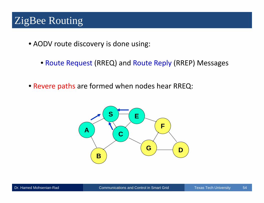
• AODV route discovery is done using:
• Route Request (RREQ) and Route Reply (RREP) Messages
• Revere paths are formed when nodes hear RREQ:
A
S EF
B
C
G D

ZigBee Routing
Dr. Hamed Mohsenian-Rad Texas Tech UniversityCommunications and Control in Smart Grid 55
• AODV route discovery is done using:
• Route Request (RREQ) and Route Reply (RREP) Messages
• RREQ flooding continues in the network:
A
S EF
B
C
G D

ZigBee Routing
Dr. Hamed Mohsenian-Rad Texas Tech UniversityCommunications and Control in Smart Grid 56
• AODV route discovery is done using:
• Route Request (RREQ) and Route Reply (RREP) Messages
• Revere paths are formed when nodes hear RREQ:
A
S EF
B
C
G D

ZigBee Routing
Dr. Hamed Mohsenian-Rad Texas Tech UniversityCommunications and Control in Smart Grid 57
• AODV route discovery is done using:
• Route Request (RREQ) and Route Reply (RREP) Messages
• RREP message(s) is/are sent through reverse path(s):
A
S EF
B
C
G D

ZigBee Routing
Dr. Hamed Mohsenian-Rad Texas Tech UniversityCommunications and Control in Smart Grid 58
• AODV route discovery is done using:
• Route Request (RREQ) and Route Reply (RREP) Messages
•This will lead to forming / discovering forward path(s):
A
S EF
B
C
G D

ZigBee Building Solutions
Dr. Hamed Mohsenian-Rad Texas Tech UniversityCommunications and Control in Smart Grid 59
• Automatic Notification: Call the owner if problem occurs.
• Door Control: When the door is locked, lights are turned off.
www.ti.com

ZigBee Building Solutions
Dr. Hamed Mohsenian-Rad Texas Tech UniversityCommunications and Control in Smart Grid 60
•Smart appliances can also communicate with smart meters.
• Example: They can obtain prices and adjust their load. (Topic 4!)
www.ti.com

ZigBee Building Solutions
Dr. Hamed Mohsenian-Rad Texas Tech UniversityCommunications and Control in Smart Grid 61
•ZigBee solutions by Texas Instrument (TI) at different layers:
• Refer to TI’s ZigBee pages for more detail.
www.ti.com

ZigBee Collocation with WiFi
Dr. Hamed Mohsenian-Rad Texas Tech UniversityCommunications and Control in Smart Grid 62
• In addition to medium access control:
• They should automatically avoid common channels.
Ref: P. Yi et a
l.
• ZigBee and WiFi collocate at 2.4 GHz Frequency Band

ZigBee Collocation with WiFi
Dr. Hamed Mohsenian-Rad Texas Tech UniversityCommunications and Control in Smart Grid 63
• ZigBee (or WiFi or both) should search for unused channels.
Ref: P. Yi et a
l.
• ZigBee and WiFi collocate at 2.4 GHz Frequency Band
WiFi:
ZigBee:
(3 Orthogonal Channels)

ZigBee Collocation with WiFi
Dr. Hamed Mohsenian-Rad Texas Tech UniversityCommunications and Control in Smart Grid 64
• An Algorithm for ZigBee Channel Switching:
• PER: Packet Error Rate• To be checked by End‐Device
• LQI: Link Quality Indicator• To be checked by Router / Coordinator
• Strength of Received Packets
• From 0 to 255 [Strongest]
• ED: Energy Detection
• RSSI: Received Signal Strength Indicator
Ref: P. Yi et a
l.

ZigBee Collocation with WiFi
Dr. Hamed Mohsenian-Rad Texas Tech UniversityCommunications and Control in Smart Grid 65
• Experimental Results by P. Yi et al. to obtain:
• Safe Distance
• Safe Offset Frequency
• WiFI Uplink and Downlink as source of interference on ZigBee:
Ref: P. Yi et a
l.
PER vs Distance (Meter)

ZigBee Collocation with WiFi
Dr. Hamed Mohsenian-Rad Texas Tech UniversityCommunications and Control in Smart Grid 66
• At 7 MHz Frequency Offset, “Safe Distance” is 5 Meter.
PER vs Distance (Meter)
Ref: P. Yi et a
l.

ZigBee Collocation with WiFi
Dr. Hamed Mohsenian-Rad Texas Tech UniversityCommunications and Control in Smart Grid 67
• 8 MHz is “Safe Frequency Offset” regardless of Distance.
• We can do similar experiments for other technologies.
• One can also study ZigBee interference on WiFi [the reverse!].
Ref: P. Yi et a
l.
PER vs Distance (Meter)

Z-Wave
Dr. Hamed Mohsenian-Rad Texas Tech UniversityCommunications and Control in Smart Grid 68
• An alternative home area networking technology for ZigBee:
• To resolve ZigBee/WiFi collocation problem.
• Z‐Wave operates at around 900 MHz band
• It does not collocate with WiFi
• It may compete with some cordless telephones
Z-Wave
Dr. Hamed Mohsenian-Rad Texas Tech UniversityCommunications and Control in Smart Grid 69
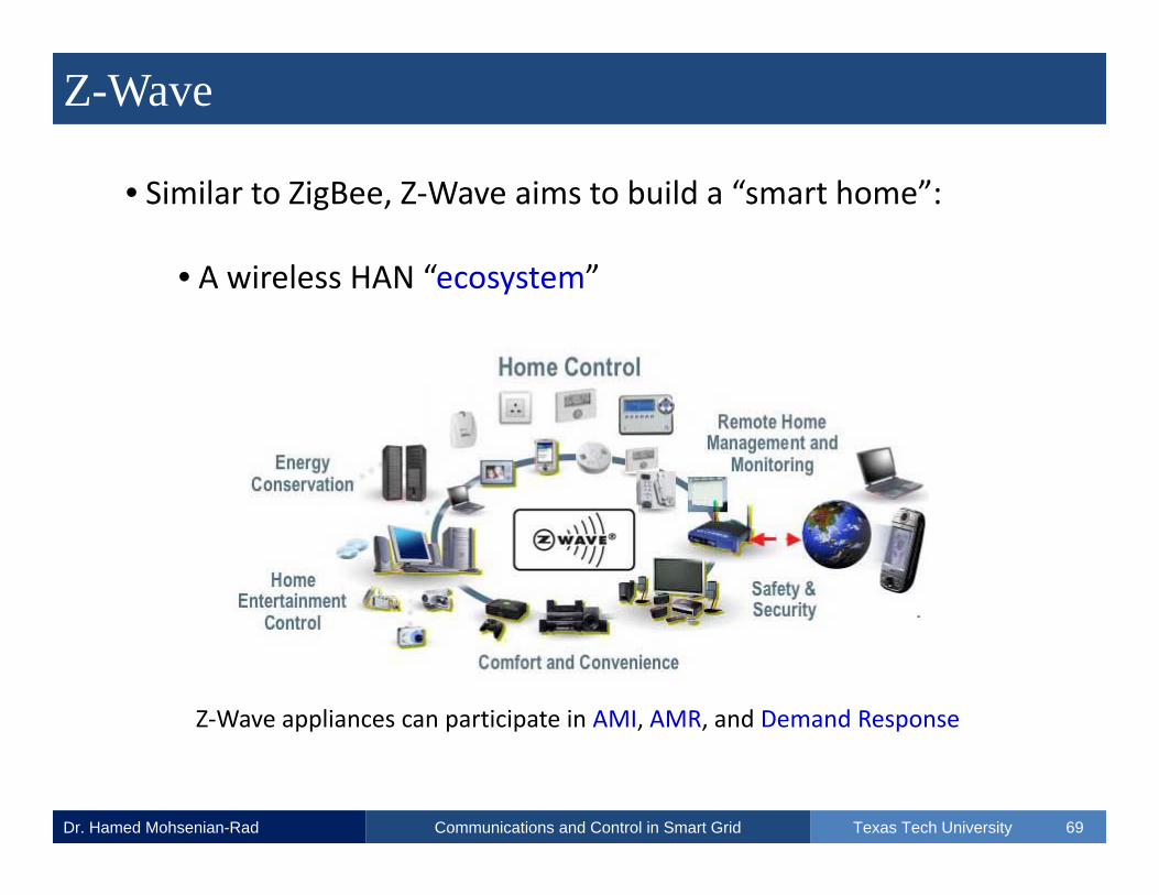
• Similar to ZigBee, Z‐Wave aims to build a “smart home”:
• A wireless HAN “ecosystem”
Z‐Wave appliances can participate in AMI, AMR, and Demand Response

Smart Grid Communications
Dr. Hamed Mohsenian-Rad Texas Tech UniversityCommunications and Control in Smart Grid 70
Wireless Mesh Networks(Metropolitan Area)

Wireless Mesh Networks (WMNs)
Dr. Hamed Mohsenian-Rad Texas Tech UniversityCommunications and Control in Smart Grid 71
• WMNs are composed of several wireless access points (routers).
• Usually WiFi or WiMax Routers
• Together, they create a fully wireless communication backbone:
• To serve wireless mesh clients (fixed / mobile)
• The WMN can be connected to the Internet or other networks:
• Through a few gateway routers

Wireless Mesh Networks (WMNs)
Dr. Hamed Mohsenian-Rad Texas Tech UniversityCommunications and Control in Smart Grid 72
• Example: a WMN with Internet and Cellular Connectivity:
Fully WirelessBackbone
Ref: Ak
yildizet al.

Wireless Mesh Networks (WMNs)
Dr. Hamed Mohsenian-Rad Texas Tech UniversityCommunications and Control in Smart Grid 73
• Example: Wireless Mesh Routers
Ref: Ak
yildizet al.
With Two Network Interface Cards (NICs)
With One Network Interface Card
Q: What is the benefit of having multiple NICs on a Wireless Mesh Rouet?

Wireless Mesh Networks (WMNs)
Dr. Hamed Mohsenian-Rad Texas Tech UniversityCommunications and Control in Smart Grid 74
• Example: Wireless Mesh Clients
Ref: Ak
yildizet al.
(a) Laptop, (b) PDA, (c) Wi‐Fi IP Phone and (d) Wi‐Fi RFID Reader.

WMNs Applications Before Smart Grid
Dr. Hamed Mohsenian-Rad Texas Tech UniversityCommunications and Control in Smart Grid 75
• Some of the Initial Applications of WMNs included:
• Community Networks
• Enterprise Networks
• Local Area Networks for Hotels, Malls, Parks, Trains, etc.
• Metropolitan Area Networks
• City‐wide WMNs have been deployed in multiple U.S. cities.

City-Wide Wireless Mesh Networking
Dr. Hamed Mohsenian-Rad Texas Tech UniversityCommunications and Control in Smart Grid 76
• Tempe, AZ Wireless Mesh Network
• Nearly 600 Mesh Access Points
• Coverage to an Area of 40 Square Miles
• Project Completed in only 120 days!

WMNs Benefits
Dr. Hamed Mohsenian-Rad Texas Tech UniversityCommunications and Control in Smart Grid 77
• Some of the advantages of WMNs:
• Low up‐front costs
• Ease of incremental deployment
• Ease of maintenance
• The wireless mesh clients can also be:
• Smart Meters, Sensors, Sub‐stations, etc.

WMNs for Smart Grid Communications
Dr. Hamed Mohsenian-Rad Texas Tech UniversityCommunications and Control in Smart Grid 78
www.trop
os.com
Mesh Router
Aggregator
Video to Watch: http://www.youtube.com/watch?v=09dhjDcaT7g

Tropos Wireless Mesh Routers for Smart Grid
Dr. Hamed Mohsenian-Rad Texas Tech UniversityCommunications and Control in Smart Grid 79
Wireless Technology: IEEE 802.11b/g/n
Frequency Band: 2.4‐2.483 GHz
Media Access Protocol: CSMA/CA with ACK
Dimensions: 15.16” high x 6.97” wide x 2.01 deep
Weight: 4.0 lbs
Wind survivability: >165 mph
Communication Range: About 100 mTropos 1410 Wireless Mesh Routers

WMNs Challenges
Dr. Hamed Mohsenian-Rad Texas Tech UniversityCommunications and Control in Smart Grid 80
• Key challenges in WMNs:
• Wireless Interference and Frequent Collisions
• Wireless Multi‐hop Transmissions (e.g., for TCP connections)
• Congestion at Gateways (Q: Why?)
• DoE has requirements for Smart Grid Communications [will see]:
• Packet Loss and Delay (Q: How can we assure these?)

Modeling Packet Loss in WMNs
Dr. Hamed Mohsenian-Rad Texas Tech UniversityCommunications and Control in Smart Grid 81
• Consider two wireless links i and j:
•Pi: transmit power of link i’s transmitter node
•Gij: channel gain from link j’s transmitter to link i’s receiver.
• A simple model for Gij = k (dij)‐2, where dij is the distance.
t1
r1t2
r2
Link 1Link 2
G21

Modeling Packet Loss in WMNs
Dr. Hamed Mohsenian-Rad Texas Tech UniversityCommunications and Control in Smart Grid 82
• Received Signal Power at link i’s receiver node:
• Received Interference Power at link i’s receiver from j’s transmitter
• Similarly, we can obtain interference power from all other links.
iiiPG
jij PG

Modeling Packet Loss in WMNs
Dr. Hamed Mohsenian-Rad Texas Tech UniversityCommunications and Control in Smart Grid 83
• We can define signal to interference ratio (SIR) for link i as:
• For correct reception of the packet, it is required that
• Otherwise, the packet is lost.
ikkik
iiii PG
PGSIR Signal Power
Aggregate Interference Power
thi SIRSIR (Threshold)

Modeling Packet Loss in WMNs
Dr. Hamed Mohsenian-Rad Texas Tech UniversityCommunications and Control in Smart Grid 84
• The probability of losing the packet on link i:
• Key Question: Why are we talking about “probability” here?
• What is the “stochastic/random” part?
ik
kikth
iii
thii
PGSIRPG
SIRSIRO
Prob
Prob(Outage)

Modeling Packet Loss in WMNs
Dr. Hamed Mohsenian-Rad Texas Tech UniversityCommunications and Control in Smart Grid 85
• Obviously not all nodes transmit at all times!
• We assume some random distribution for packet transmission.
• If nodes transmit following independent exponential distributions:
[Proof: See Appendix I in IEEE TWC paper by S. Kandukuri and S. Boyd]
ik
iii
kikthi
PGPGSIR
O1
11

Modeling Packet Loss in WMNs
Dr. Hamed Mohsenian-Rad Texas Tech UniversityCommunications and Control in Smart Grid 86
• Let us consider the packet loss model again:
•Probability of packet loss increases If:
• Link i transmits with lower power
• Interfering links transmit with higher power
• Interfering links get closer
• There are more interfering links in the neighborhood
ik
iii
kikthi
PGPGSIR
O1
11

Modeling Packet Loss in WMNs
Dr. Hamed Mohsenian-Rad Texas Tech UniversityCommunications and Control in Smart Grid 87
• The model so far only gives “per‐link” packet loss.
• Q: How about end‐to‐end packet loss probability?
Smart Meter
AggregatorMesh Router
A fully wireless multi‐hop communication!

Modeling Packet Loss in WMNs
Dr. Hamed Mohsenian-Rad Texas Tech UniversityCommunications and Control in Smart Grid 88
• End‐to‐end Probability of Packet Loss (Q: Why?):
Smart Meter
Aggregator
“Per‐link” Loss Probabilities: O1, O2, O3, and O4.
Link 1
Link 2 Link 3 Link 4
)1)(1)(1)(1(1 4321 OOOOOPath

Modeling Packet Loss in WMNs
Dr. Hamed Mohsenian-Rad Texas Tech UniversityCommunications and Control in Smart Grid 89
• In general, for a path with R as the set of wireless links:
• For each path in WMN (e.g., AMI), we can calculate Opath if know
• Locations of the mesh routers and clients (channel gains)
• Transmit power of mesh routers and clients
• The SIR threshold values for the technology being used
Ri
iPath OO )1(1
[Example: You can check if it satisfies the DoE requirements!]

Modeling Packet Loss in WMNs
Dr. Hamed Mohsenian-Rad Texas Tech UniversityCommunications and Control in Smart Grid 90
• We want low “per‐link” loss rates for links closer to aggregator:
Smart Meter
Aggregator
Smart Meter
Link 1
Link 2 Link 3 Link 4
Link 5
Link 6
O4 should be low! (Q: Why?)

Modeling Packet Loss in WMNs
Dr. Hamed Mohsenian-Rad Texas Tech UniversityCommunications and Control in Smart Grid 91
•Q: How can we assure required packet loss bounds for all path?
• First of all, we should not have paths that are too long!
• This requires having several gateways in large WMNs.
• Second, we need to do resource management:
• Power allocation, channel assignment, etc.

Channel Assignment in WMNs
Dr. Hamed Mohsenian-Rad Texas Tech UniversityCommunications and Control in Smart Grid 92
• Assume that we use WiFi technology for our WMN.
• Let us look at the available 11 channels in IEEE 802.11b:
1 2 3 4 5 6 7 8 9 10 11
Partially Overlapping: 1 and 2 Non‐Overlapping: 1 and 6 and 11

Channel Assignment in WMNs
Dr. Hamed Mohsenian-Rad Texas Tech UniversityCommunications and Control in Smart Grid 93
• We assign different non‐overlapping channels to different links:
Smart Meter
Aggregator
Link 1
Link 2 Link 3 Link 4
Ch 1
Ch 6 Ch 11 Ch 1
‐ Links 1, 2, and 3 will no longer interfere on each other.
‐ Links 1 and 4 may interfere, but they are far from each other.
Such multi‐channel deployment requires mesh routers with multiple NICs. (Q: Why?)

Channel Assignment in WMNs
Dr. Hamed Mohsenian-Rad Texas Tech UniversityCommunications and Control in Smart Grid 94
• Same idea applies to a more complex network:
• Channel assignment depends on the number of NICs per node.
Aggregator

Channel Assignment in WMNs
Dr. Hamed Mohsenian-Rad Texas Tech UniversityCommunications and Control in Smart Grid 95
• Same idea applies to a more complex network:
• Channel assignment depends on the number of NICs per node.
Aggregator1
6
11
11
6
1
11
6
6
11
11
6
1
1
1

Channel Assignment in WMNs
Dr. Hamed Mohsenian-Rad Texas Tech UniversityCommunications and Control in Smart Grid 96
• Same idea applies to a more complex network:
• Knowing NIC = 2: Q: Do you see more than 2 channels per node?
Aggregator1
6
11
11
6
1
11
6
6
11
11
6
1
1
1

Channel Assignment in WMNs
Dr. Hamed Mohsenian-Rad Texas Tech UniversityCommunications and Control in Smart Grid 97
• Here, we have three different contention domains:
• Channel 1: Seven Links
• Channel 6: Five Links
• Channel 11: Four Links
• Note that links on channel 1 are far from each other
• We can better remove interference with more channels/NICs.

ATCP for WMNs
Dr. Hamed Mohsenian-Rad Texas Tech UniversityCommunications and Control in Smart Grid 98
• When it comes to wireless networks:
• Packet loss due to link failure/interference can affect TCP.
• The problem: TCP back‐off every time a packet is lost.
• One Solution: Ad‐hoc Transmission Control Protocol (TCP)
• ATCP uses network feedback:
• ICMP Destination Unreachable (when a path breaks)
• Early Congestion Notification (when there is congestion)

ATCP for WMNs
Dr. Hamed Mohsenian-Rad Texas Tech UniversityCommunications and Control in Smart Grid 99
• The key idea: We want to distinguish:
• Packet loss due to congestion
• Packet loss due to wireless interference/collision
• ECN Flags: Indication of congestion
• Timeout and 3 duplicate ACKs: Indication of collision/link problem
[Link problems can be because of mobility]

ATCP for WMNs
Dr. Hamed Mohsenian-Rad Texas Tech UniversityCommunications and Control in Smart Grid 100
• ATCP in the TCP/IP Stack:
• It only affects the TCP sender side. It is a cross‐layer solution.

ATCP for WMNs
Dr. Hamed Mohsenian-Rad Texas Tech UniversityCommunications and Control in Smart Grid 101
• ATCP / TCP Behavior:
• Timeout and 3rd Duplicate ACK:
• Retransmit the segment
• No Congestion Control Reaction
• Assumed to be due to link collision
•ACK with ECN Flag:
• Invokes Congestion Control

ATCP for WMNs
Dr. Hamed Mohsenian-Rad Texas Tech UniversityCommunications and Control in Smart Grid 102
• ATCP / TCP Behavior:
• ICMP Destination Unreachable Message:
• Stops Transmission
• Enters “Persist Mode”
• Starts Persist Timer
• Probes for Path Availability when Timer Expires
• Resume Transmission when New Path Found

Smart Grid Communications
Dr. Hamed Mohsenian-Rad Texas Tech UniversityCommunications and Control in Smart Grid 103
IEC 61850 (Communications of Substations)
IEC 61850 Overview
Dr. Hamed Mohsenian-Rad Texas Tech UniversityCommunications and Control in Smart Grid 104
• IEC: International Electrotechnical Commission
• IEC 61850
• Smart Grid Communications Standard
• Communications across Intelligent Electronic Devices (IEDs)
• Focus: Sub‐stations (but also supports meters, etc.)
• Runs over TCP/IP networks

IEC 61850 Overview
Dr. Hamed Mohsenian-Rad Texas Tech UniversityCommunications and Control in Smart Grid 105
• Example Sub‐station:
Ref: AB
B Sw
itzerland
Ltd Corpo
rate Research

IEC 61850 Overview
Dr. Hamed Mohsenian-Rad Texas Tech UniversityCommunications and Control in Smart Grid 106
• IEC 61850 Aims to provide inter‐operability
• Key focus: IEC 61850 provides a comprehensive model forhow power system devices should organize data in a mannerthat is consistent across all types and brands of devices.
• The IEC 61850 devices are intended to be plug‐and‐play.
• They are configured by uploading simple configuration files.

IEC 61850 Overview
Dr. Hamed Mohsenian-Rad Texas Tech UniversityCommunications and Control in Smart Grid 107
• IEC 61850 Network Architecture:
• XCBR: Circuit Breaker, MMXU1: Measurement Unit for Feeder 1, …
Physical Device(Data Concentrator)
Logical Devices / Nodes
XCBR
MMXU1
MMXU2

IEC 61850 Overview
Dr. Hamed Mohsenian-Rad Texas Tech UniversityCommunications and Control in Smart Grid 108
• Data types to be transmitted for each logical device:
• Should follow certain specifications:
Object Name Data Class Name (Data Structure)

IEC 61850 Overview
Dr. Hamed Mohsenian-Rad Texas Tech UniversityCommunications and Control in Smart Grid 109
• Data types to be transmitted for each logical device:
Object Name Data Class Name (Data Structure)
(Cont.)

IEC 61850 Data Classes
Dr. Hamed Mohsenian-Rad Texas Tech UniversityCommunications and Control in Smart Grid 110
• Example: SPS: Single Point Status
(Cont.)
ST: Status
DC: Description
SV: Substitution

IEC 61850 Data Classes
Dr. Hamed Mohsenian-Rad Texas Tech UniversityCommunications and Control in Smart Grid 111
• Other Data Classes:
• Status information (binary, integer):
• SPS: Single Point Status
• DPS: Double Point Status
• INS: Integer Status
• ACT: Protection Activation info
• ACD: Activation Info Directional Protection
• SEC: Security Violation Counting
• BCR: Binary Counter Reading

IEC 61850 Data Classes
Dr. Hamed Mohsenian-Rad Texas Tech UniversityCommunications and Control in Smart Grid 112
• Other Data Classes:
• Control Status:
• SPC: Single Point Control
• DPC: Double Point Control
• INC: Integer Status Control
• BSC: Binary Controlled Step Position Info
• ISC: Integer Controlled Step Position Info
• Just like the example for SPS, each item has a data structure.

IEC 61850 Logical Nodes
Dr. Hamed Mohsenian-Rad Texas Tech UniversityCommunications and Control in Smart Grid 113
• Recall that we used names XCBR, MMXU1, … for logical nodes.
• The first letter indicates the type for the logical node:
• X: Switchgear
• M: Metering and Measurement
• A: Automatic Control
• C: Supervisory Control
• G: Generic Function

IEC 61850 Logical Nodes
Dr. Hamed Mohsenian-Rad Texas Tech UniversityCommunications and Control in Smart Grid 114
• Recall that we used names XCBR, MMXU1, … for logical nodes.
• The first letter indicates the type for the logical node:
• I: Interfacing
• P: Protection
• S: Sensors
• T: Instrument Transformer
• Y: Power Transformers Z: Other devices

IEC 61850 Logical Nodes
Dr. Hamed Mohsenian-Rad Texas Tech UniversityCommunications and Control in Smart Grid 115
• Example: Can you identify different logical nodes?
Ref: AB
B Sw
itzerland
Ltd Corpo
rate Research

IEC 61850 Logical Nodes
Dr. Hamed Mohsenian-Rad Texas Tech UniversityCommunications and Control in Smart Grid 116
• IEC 61850 gives an object‐oriented model for communications.
• Example for Object Names:
• We would like to know if the circuit breaker logical node XCBR1 in logical device Relay 1 is in the remote or local mode of operation.

IEC 61850 Logical Nodes
Dr. Hamed Mohsenian-Rad Texas Tech UniversityCommunications and Control in Smart Grid 117
• The object names are used to form MMS messages:
• MMS: Manufacturing Messaging Specification
• The messages are exchanged as application‐layer messages.
• The MMS messages are exchanged over TCP/IP networks
• LAN
• Web‐Based

Smart Grid Communications
Dr. Hamed Mohsenian-Rad Texas Tech UniversityCommunications and Control in Smart Grid 118
Power Line Communications

PLC Overview
Dr. Hamed Mohsenian-Rad Texas Tech UniversityCommunications and Control in Smart Grid 119
• Power Line Communications (PLC):
• Carrying data on a conductor also used for power transmission
• PLC is a wired communications technology
• But it can compete with wireless technologies with low cost
• Because the infrastructure already exists
• Harsh environment of the power transmission lines.

PLC Overview
Dr. Hamed Mohsenian-Rad Texas Tech UniversityCommunications and Control in Smart Grid 120
• Idea:
• Digital signal to be transmitted is modulated over power line.
• This is done by a proper coupler device.
• The signal is propagated over the power line.
• It will be decoupled and decoded at the receiver side.
Inductive coupler PLC‐Modem

PLC Overview
Dr. Hamed Mohsenian-Rad Texas Tech UniversityCommunications and Control in Smart Grid 121
• Harsh Noise Environment:
Power spectral densities of noise due to various sources
Ref: H.C. Ferreira
et a
l.

PLC Classes
Dr. Hamed Mohsenian-Rad Texas Tech UniversityCommunications and Control in Smart Grid 122
• Three classes of PLC Technologies:
• Broadband (BB):
• Operating at 1.8 – 250 MHz.
• Data Rate: Up to 200 Mbps
• Initial Application: Residential Internet Access
• Short Communication Range (few kilometers)
• Good for AMI/AMR, Not Good for sub‐stations (Q: Why?)

PLC Classes
Dr. Hamed Mohsenian-Rad Texas Tech UniversityCommunications and Control in Smart Grid 123
• Three classes of PLC Technologies:
• Broadband (BB):
Example: Residential broadband access / AMI / AMR
Gateway / Internet

PLC Classes
Dr. Hamed Mohsenian-Rad Texas Tech UniversityCommunications and Control in Smart Grid 124
• Three classes of PLC Technologies:
• Narrowband (NB):
• Operating at 3 – 500 kHz.
• United States FCC: 10‐490 kHz
• Data Rate: Up to 500 kbps (usually several kbps)
• Considered for sub‐station communications

PLC Classes
Dr. Hamed Mohsenian-Rad Texas Tech UniversityCommunications and Control in Smart Grid 125
• Three classes of PLC Technologies:
•Ultra Narrowband (UNB):
• Operating at 30 Hz – 3 kHz.
• Data Rate: Up to 100 bps (very low, but good enough!)
• Communication Range: 150 km or more
• Current Applications:
• AMI, AMR, Demand Response (Direct Load Control)

HomePlug
Dr. Hamed Mohsenian-Rad Texas Tech UniversityCommunications and Control in Smart Grid 126
• HomePlug is an industry Alliance to enable and promote PLC:
• HomePlug 1.0: Residential Internet
• HomePlug AV: Residential Cable TV
• HomePlug Green PHY: Smart Grid Applications (in‐home)
• Wired alternative/addition to ZigBee and Z‐Wave for HAN

Smart Grid Communications
Dr. Hamed Mohsenian-Rad Texas Tech UniversityCommunications and Control in Smart Grid 127
DoE Requirements for Smart Grid Communications
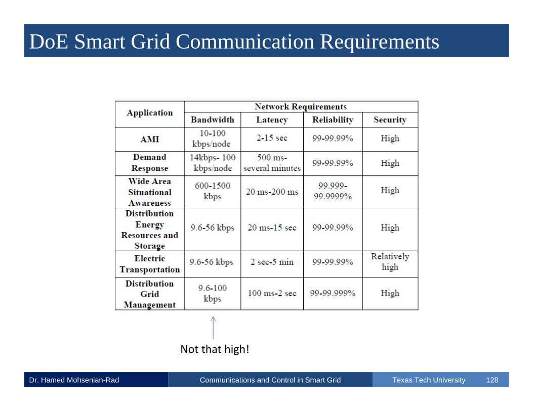
DoE Smart Grid Communication Requirements
Dr. Hamed Mohsenian-Rad Texas Tech UniversityCommunications and Control in Smart Grid 128
Not that high!

Smart Grid Communications
Dr. Hamed Mohsenian-Rad Texas Tech UniversityCommunications and Control in Smart Grid 129
Other Smart Grid Communications Technologies

Other Smart Grid Communication Technologies
Dr. Hamed Mohsenian-Rad Texas Tech UniversityCommunications and Control in Smart Grid 130
Ref: V.C. Gün
gör e
t al.

Other Smart Grid Communication Technologies
Dr. Hamed Mohsenian-Rad Texas Tech UniversityCommunications and Control in Smart Grid 131
Ref: V.C. Gün
gör e
t al.

References
Dr. Hamed Mohsenian-Rad Texas Tech UniversityCommunications and Control in Smart Grid 132
• A. Van‐Nieuwenhuyse, M. Alves, and A. Koubâa, "On the use ofthe ZigBee protocol for Wireless Sensor Networks", TechnicalReport, IPP Hurray, Jun 2006. [On‐line] http://www.open‐zb.net/publications/tr‐hurray‐060603.pdf.
• P. Yi, A. Iwayemi, and C. Zhou, "Developing ZigBee DeploymentGuideline Under WiFi Interference for Smart Grid Applications",IEEE Transactions on Smart Grid, Vol. 2, No. 1, pp. 110‐120,March 2011.
• S. Safaric and K.~Malaric, "ZigBee Wireless Standard", Proc. ofthe IEEE International Symposium on Multimedia SignalProcessing and Communications, Zadar, Croatia, June 2006.
References
Dr. Hamed Mohsenian-Rad Texas Tech UniversityCommunications and Control in Smart Grid 133
• M. Armel, "ZigBee Overview", Lecture Notes, The GeorgeWashington Univ. 2007. [On‐line] http://www.seas.gwu.edu/~cheng/388/LecNotes2007/ZigBee.pdf.
• S. C. Ergen, "ZigBee/IEEE 802.15.4 Summary", TechnicalReport, University of California ‐ Berkeley, September 2004. [On‐Line] http://pages.cs.wisc.edu/~suman/courses/838/papers/zigbee.pdf.
• ZigBee Alliance, "ZigBee and Wireless Radio FrequencyCoexistence", Document Number: Zigbee_07‐5219, June 2007,[On‐Line] www.zigbee.org.

References
Dr. Hamed Mohsenian-Rad Texas Tech UniversityCommunications and Control in Smart Grid 134
• ZigBee Alliance, "ZigBee Overview", Document Number:Zigbee_07‐5482, June 2007, [On‐Line] www.zigbee.org.
• J. Liu and S. Singh, “ATCP: TCP for mobile Ad Hoc Networks”,IEEE Journal on Selected Areas in Communications, pp. 1300‐1315, vol. 19, no. 7, July 2001.
• S. Kandukuri and S. Boyd, "Optimal power control ininterference‐limited fading wireless channels with outage‐probability specifications", IEEE Transactions on WirelessCommunications, pp. 46 ‐ 55, vol. 1, no. 1, January 2002.
• I. Akyildiz, X. Wang, and W. Wang, "Wireless Mesh Networks: ASurvey," Computer Networks, vol. 47, pp. 445‐487, March 2005.

References
Dr. Hamed Mohsenian-Rad Texas Tech UniversityCommunications and Control in Smart Grid 135
• Department of Energy, “Communications Requirements ofSmart Grid Technologies", October 5, 2010.
• G. Iyer, P. Agrawal, E. Monnerie, R.S. Cardozo, “Performanceanalysis of wireless mesh routing protocols for smart utilitynetworks”, in Proc. of the IEEE International Conference onSmart Grid Communications, Brussels, Belgium, October 2011.
• M. Erol‐Kantarci, H. T. Mouftah, “Wireless Sensor Networks forCost‐Efficient Residential Energy Management in the SmartGrid”, IEEE Transactions on Smart Grid, vol. 2, no. 2, pp. 314‐325, June 2011.

References
Dr. Hamed Mohsenian-Rad Texas Tech UniversityCommunications and Control in Smart Grid 136
• M. Adamiak, D. Baigent, and R. Mackiewicz, “IEC 61850Communication Networks and Systems In Substations: AnOverview for Users”, in Proc. of Syst. Protection Seminar, 2004.
• V. C. Güngör, D. Sahin, T. Kocak, S. Ergüt, C. Buccella, C. Cecati,G. P. Hancke, “Smart Grid Technologies: CommunicationTechnologies and Standards”, IEEE Transactions on IndustrialInformatics, vol. 7, no. 4, pp. 529‐539, November 2011.
• H.C. Ferreira, H.M. Grovk, 0. Hooijen, and A.J. Han‐Vinck,“Power Line Communications: An Overview”, Proc. of the IEEEAFRICON, Stellenbosch , South Africa, September 1996.


