Service Information Kurzübersicht Quick reference Installation und Inbetriebnahme des SPC200 Installing and commissioning the SPC200 ɤ Deutsch ɤ English ɤ Español ɤ Français ɤ Italiano ɤ Svenska 685 085 0504c Smart Positioning Controller SPC200
Transcript
Service Information
Kurzübersicht
Quick reference
Installation undInbetriebnahmedes SPC200
Installing andcommissioningthe SPC200
� Deutsch� English� Español� Français� Italiano� Svenska
Der Smart Positioning Controller SPC200 besitzt ein neuesBetriebssystem (Firmware) mit erweiterter Funktionalität.Beachten Sie die folgenden Service−Informationen.
1.1 Versions−Informationen
Die Basiseinheiten Typ SPC200−CPU−4 oder −6 und dieSubcontroller−Baugruppe Typ SPC200−SCU−AIF enthalten
jeweils ein eigenes Betriebssystem (Firmware).
VorsichtFür fehlerfreien Betrieb des SPC200 mit einer Sub�controller−Baugruppe ist es notwendig, dass dieBetriebssystem−Versionen übereinstimmen.
WinPISA ab Version 4.3 zeigt beim Aktivieren des Online−Modus eine Fehlermeldung an, wenn die Betriebssystem−Versionen nicht übereinstimmen. Mit WinPISA ab Version 4.1 zeigen Sie bei aktivem Online−Modus die Betriebssystem−Versionen im Fenster �SPC200Konfiguration" als Quickinfo (Tooltip) an, indem Sie denMauszeiger auf die entsprechende Baugruppe bewegen:
S Baugruppe SPC200−AIF−PWR:Betriebssystem−Version der Basiseinheit
S Baugruppe SPC200−SCU−AIF:Betriebssystem−Version der Subcontroller−Baugruppe.
Hinweise zu kompatiblen Betriebssystem−, WinPISA− und
Handbuch−Versionen enthält die folgende Tabelle.
Festo SPC200−... 0504c Deutsch4
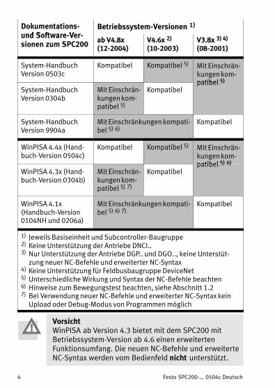
Dokumentations−und Software Ver
Betriebssystem−Versionen 1)
und Software−Ver�sionen zum SPC200
ab V4.8x(12−2004)
V4.6x 2)
(10−2003)V3.8x 3) 4)
(08−2001)
System−HandbuchVersion 0503c
Kompatibel Kompatibel 5) Mit Einschrän�kungen kom�patibel 5)
System−HandbuchVersion 0304b
Mit Einschrän�kungen kom�patibel 5)
Kompatibelpatibel 5)
System−HandbuchVersion 9904a
Mit Einschränkungen kompati�bel 5) 6)
Kompatibel
WinPISA 4.4x (Hand�buch−Version 0504c)
Kompatibel Kompatibel 5) Mit Einschrän�kungen kom�patibel 5) 6)
WinPISA 4.3x (Hand�buch−Version 0304b)
Mit Einschrän�kungen kom�patibel 5) 7)
Kompatibelpatibel 5) 6)
WinPISA 4.1x(Handbuch−Version0104NH und 0206a)
Mit Einschränkungen kompati�bel 5) 6) 7)
Kompatibel
1) Jeweils Basiseinheit und Subcontroller−Baugruppe2) Keine Unterstützung der Antriebe DNCI..3) Nur Unterstützung der Antriebe DGP.. und DGO.., keine Unterstüt�
zung neuer NC−Befehle und erweiterter NC−Syntax4) Keine Unterstützung für Feldbusbaugruppe DeviceNet5) Unterschiedliche Wirkung und Syntax der NC−Befehle beachten6) Hinweise zum Bewegungstest beachten, siehe Abschnitt 1.27) Bei Verwendung neuer NC−Befehle und erweiterter NC−Syntax kein
Upload oder Debug−Modus von Programmen möglich
VorsichtWinPISA ab Version 4.3 bietet mit dem SPC200 mitBetriebssystem−Version ab 4.6 einen erweitertenFunktionsumfang. Die neuen NC−Befehle und erweiterteNC−Syntax werden vom Bedienfeld nicht unterstützt.
Festo SPC200−... 0504c Deutsch 5
WarnungFehler bei der Parametrierung können Personen− und
Sachschäden verursachen, wenn Sie den Regler durchein 1−Signal am Eingang ENABLE freigeben.Geben Sie den Regler nur dann frei, wenn das Achs�system fachgerecht installiert und parametriert ist.
1.2 Hinweise zum Bewegungstest
WarnungDer Regler ist beim Bewegungstest abgeschaltet. Daherkönnen sich die Pneumatischen Achsen bei eingeschal�tetem Versorgungsdruck unwillkürlich und unkontrol�liert in Bewegung setzen. Die eingestellten Software�endlagen sind unwirksam.Wenn Sie den Bewegungstest bei eingeschaltetemVersorgungsdruck durchführen möchten:S Stellen Sie sicher, dass der gesamte Verfahrbereich
der Pneumatischen Achsen frei bleibt.S Weisen Sie auch Außenstehende durch geeigneteWarnschilder oder Absperrungen auf die Gefahr hin.
S Halten Sie die Beschleunigungskräfte gering. Hierzueinen geringen Versorgungsdruck von maximal 3�bareinstellen und Nutz− und Werkzeuglast entfernen.
Beachten Sie folgende Hinweise zur Durchführung des
Bewegungstests mit den verschiedenen SPC200−Betriebs�system− und WinPISA−Versionen.
Festo SPC200−... 0504c Deutsch6
Durchführung des Bewegungstests mit verschiedenenSPC200−Betriebssystem− und WinPISA−Versionen
Ab BS V4.6 mit WinPISA 4.3
1. Vor dem Bewegungstest: 0−Signal an ENABLE.2. Bewegungstest für gewünschte Achse aufrufen
(siehe System− oder WinPISA−Handbuch).3. 1−Signal an ENABLE anlegen.4. Bewegungstest durchführen: Ventilspannung ändern
und Bewegungsrichtung prüfen. 0−Signal an ENABLE setzt Ventilspannung auf 5 V undbricht Bewegungstest ab (mit Fehlermeldung).
5. Bewegungstest beenden, 0−Signal an ENABLEanlegen.
Ab BS V4.6 mit WinPISA 4.1xoder früher
Beim Bewegungstest das neu definierte Signalverhaltendes SPC200 beachten.1. Vor dem Bewegungstest: 0−Signal an ENABLE.2. Bewegungstest aufrufen (siehe WinPISA−Handbuch).3. Achse wählen.4. 1−Signal an ENABLE anlegen.5. Bewegungstest für gewählte Achse durchführen:
Ventilspannung ändern und Bewegungsrichtungprüfen.
6. 0−Signal an ENABLE anlegen.7. Andere Achse wählen und Schritt 3. bis 6. wiederho�
len oder Dialogfenster �Bewegungstest" schließen.
BS V3.80mit WinPISA 4.3,WinPISA 4.1xoder früher
S Legen Sie vor Aufruf des Bewegungstest 1−Signal anENABLE, START und STOP an. Bei WinPISA 4.3: abweichend von den angezeigtenMeldungen ist immer 1−Signal an ENABLE erforder�lich.
Festo SPC200−... 0504c Deutsch 7
2 Benutzerhinweise
Der SPC200 dient, in Verbindung mit den zugehörigenBaugruppen und Modulen, bestimmungsgemäß als Posi�tioniersteuerung und Lageregler für Pneumatische Achsen
sowie als Positioniersteuerung für elektrische Achsen.
Diese Kurzübersicht enthält eine Zusammenfassung dernotwendigen Schritte zur Inbetriebnahme eines Positio�niersystems mit Pneumatischen Achsen.
Ausführliche Informationen zum SPC200 finden Sie imSystem−Handbuch zum SPC200 (Typ P.BE−SPC200−...).Informationen zu speziellen Erweiterungsbaugruppenfinden Sie in den Beschreibungen zur jeweiligen Bau�gruppe.
VorsichtDiese Kurzübersicht richtet sich an ausgebildete Fach�leute der Steuerungs− und Automatisierungstechnik,die Erfahrung mit der Installation und Inbetriebnahmedes SPC200 besitzen.Beachten Sie unbedingt die sicherheitstechnischen
Hinweise im System−Handbuch zum SPC200, Typ P.BE−SPC200−...�.
WarnungSchalten Sie vor Installations− und Wartungsarbeiten
Folgendes in der angegebenen Reihenfolge aus:1.Druckluftversorgung2. Last− und Betriebsspannungsversorgung am SPC200und ggf. Lastspannungsversorgung am Achsinter−face−Strang.
Festo SPC200−... 0504c Deutsch8
3 Installationshinweise Pneumatische Achse
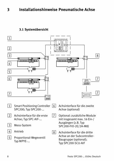
3.1 Systemübersicht
POWERDIAGOUTPUT
PNP0 1
INPUT/OUTPUT
INPUT0 1
1
2
3
4
5
6
7
8
7
7
1 Smart Positioning ControllerSPC200; Typ SPC200−...
2 Achsinterface für die ersteAchse; Typ SPC−AIF−...
3 Mess−System
4 Antrieb
5 Proportional−Wegeventil Typ MPYE−...
6 Achsinterface für die zweiteAchse (optional)
7 Optional: zusätzliche Modulemit insgesamt max. 16 Ein−/Ausgängen (z.B. TypSPC200−FIO−2E/2A−M8)
8 Achsinterface für die dritteAchse an der Subcontroller−Baugruppe (optional); Typ SPC200−SCU−AIF
Festo SPC200−... 0504c Deutsch 9
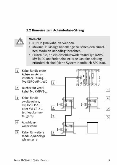
3.2 Hinweise zum Achsinterface−Strang
VorsichtS Nur Originalkabel verwenden.S Maximal zulässige Kabellänge zwischen den einzel�
nen Modulen unbedingt beachten.S Prüfen Sie, ob ein Abschlusswiderstand Typ KABS−M9−R100 und/oder eine externe Lasteinspeisungerforderlich sind (siehe System−Handbuch SPC200).
1 Kabel für die ersteAchse am Achs−interface−Strang, Typ�KSPC−AIF−1−WD
2 Buchse für Ventil�kabel Typ KMPYE−...
3 Kabel für die zweite Achse, Typ KVI−CP−1−... oder KVI−CP−2−...(schleppketten−tauglich)
4 Abschluss�widerstand
5 Kabel für weitereModule, Kabeltypwie unter 3
1
2
3
4
2
2
1
5
Festo SPC200−... 0504c Deutsch10
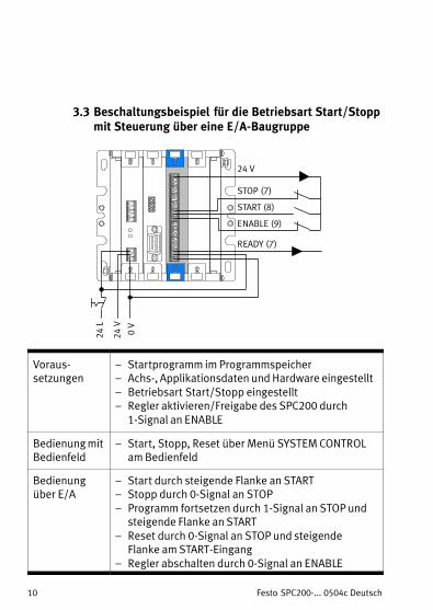
3.3 Beschaltungsbeispiel für die Betriebsart Start/Stoppmit Steuerung über eine E/A−Baugruppe
START (8)
STOP (7)
READY (7)
24 V
ENABLE (9)
0 V
24 V
24 L
Voraus−setzungen
� Startprogramm im Programmspeicher� Achs−, Applikationsdaten und Hardware eingestellt� Betriebsart Start/Stopp eingestellt� Regler aktivieren/Freigabe des SPC200 durch
1−Signal an ENABLE
Bedienung mitBedienfeld
� Start, Stopp, Reset über Menü SYSTEM CONTROLam Bedienfeld
Bedienungüber E/A
� Start durch steigende Flanke an START� Stopp durch 0−Signal an STOP
� Programm fortsetzen durch 1−Signal an STOP undsteigende Flanke an START
� Reset durch 0−Signal an STOP und steigendeFlanke am START−Eingang
� Regler abschalten durch 0−Signal an ENABLE
Festo SPC200−... 0504c Deutsch 11
4 Checkliste zur InbetriebnahmePneumatischer Achsen mit WinPISA
Die folgende Checkliste gibt einen Überblick über dienotwendigen Schritte zur Inbetriebnahme PneumatischerAchsen mit WinPISA. Ausführliche Informationen findenSie in der Online−Hilfe oder im Handbuch zu WinPISA.
Schritt Beschreibung
Zur Inbetriebnahme zunächst die gewünschte Hardwarekonfigurationam SPC200 herstellen.
1. Nachbilden der vorhandenen Hardwarekonfiguration ineinem WinPISA−ProjektZur Inbetriebnahme zunächst die gewünschteHardwarekonfiguration am SPC200 herstellen.S Hardwarekonfiguration auslesen (Empfehlung),S oder Hardwarekonfiguration manuell einstellen.
Pneumatische Achse in Betrieb nehmen.
2. Achsspezifische Parameter einstellen und Projekt in denSPC200 laden (Pneumatische Achse)S Achs− und Applikationsdaten für alle Achsen einstellen.S Speziell Einbauversatz, Projektnullpunkt und Software�
endlagen gemäß Anlage prüfen.Die Reglerdaten werden i.d.R. nicht verändert.
3. Verschlauchung prüfenS Hierzu Bewegungstest durchführen (siehe auch AbschnittS Hierzu Bewegungstest durchführen (siehe auch Abschnitt
1.2 oder WinPISA− bzw. System−Handbuch).Hinweis: Beachten Sie die Informationen im Abschnitt 1.
8. Betriebsart und Startprogramme einstellenEmpfehlung (zur Erst−Inbetriebnahme):S Testprogramm als Startprogramm A festlegen.S Startprogramm B deaktivieren (Startpr. B=***).S Betriebsart Start/Stopp einstellen (leichtere Test−
möglichkeiten).
9. Programm im Debug Modus oder im Dauerlauf testenVoraussetzungen:� Programm im Programmspeicher� Achs− und Applikationsdaten eingestellt und Projekt in den
SPC200 geladen.� Betriebsart Start/Stopp und Startprogramm eingestellt.� An ENABLE und STOP liegt 1−Signal an.
Festo SPC200−... 0504c English 13
1 Service informationEnglish
The SPC200 Smart Positioning Controller possesses a newoperating system (firmware) with extended functions.Please note the following service information.
1.1 Version status information
The basic units types SPC200−CPU−4 or −6 and the subcon�troller module type SPC200−SCU−AIF each have their own
operating system (firmware).
CautionFor faultless operation of the SPC200 with a subcon�troller module it is necessary that the operating system
versions are the same.
WinPISA as from version 4.3 will display a fault message ifthe operating system versions are not the same when the
online mode is activated. With WinPISA as from version 4.1, you can display the
operating system versions in active online mode in the
window �SPC200 configuration" as �quickinfo" (tool tip),by placing the mouse cursor on the appropriate compo�nent.
S Module SPC200−AIF−PWR:Operating system version of the basic unit
S Module SPC200−SCU−AIF:Operating system version of the subcontroller module
Notes on compatible operating system versions, WinPISAand manual versions can be found in the following table.
1) In each case basic unit and subcontroller module2) Does not support drives type DNCI..3) Only support for drives DGP.. and DGO.., does not support new NC
commands and extended NC syntax4) Does not support field bus module DeviceNet5) Note the different effect and syntax of the NC commands6) Note the instructions on the movement test, see section 1.27) If you use the new NC commands and extended NC syntax, it is not
possible to upload programs or to use the debug mode
CautionWinPISA as from Version 4.3 offers an extended scope offunctions with the SPC200 with operating system asfrom 4.6. The new NC commands and extended NCsyntax are not supported by the control panel.
Festo SPC200−... 0504c English 15
WarningFaults in parametrizing can cause injury to human
beings and damage to property if the controller isenabled with a 1−signal at the ENABLE input.Enable the controller only if the axis system is correctlyinstalled and parametrized.
1.2 Notes on the movement test
WarningThe controller is switched off during the movement test.This is to prevent the pneumatic axes from making
sudden uncontrolled movements when the supply pres�sure is switched on. The set software end positions
have no effect.If you wish to carry out the movement test with the sup�ply pressure switched on:S Make sure that the complete positioning range of thepneumatic axes is free.
S Point out the danger to other people by means ofsuitable warning signs or protective screens.
S Keep the acceleration forces at a low level. To do thisset a low supply pressure of maximum 3�bar andremove the work load and the tool load.
Note the following instructions on carrying out the move�ment test with the different SPC200 operating system versions and WinPISA versions.
Festo SPC200−... 0504c English16
Carrying out the movement test with the different SPC200operating system versions and WinPISA versions
As fromoperating
system V4.6withWinPISA�4.3
1. Before the movement test: 0−signal at ENABLE2. Access the movement test for the desired axis
(see�system manual or WinPISA manual).3. Apply a 1−signal at ENABLE.4. Carry out the movement test: Modify the valve
voltage and check the direction of movement. A 0−signal at ENABLE will set the valve voltage to 5 Vand interr. the movement test (with fault message).
5. In order to conclude the movement test, apply a0−signal at ENABLE.
As fromoperating
system V4.6withWinPISA�4.1xor earlier
Note the newly defined signal behaviour of the SPC200during the movement test.1. Before the movement test: 0−signal at ENABLE2. Access the movement test (see WinPISA manual).3. Select the axis.4. Apply a 1−signal at ENABLE.5. Carry out the movement test for the selected axis:
Modify the valve voltage and check the direction ofmovement.
6. Apply a 0−signal at ENABLE.7. Select another axis and repeat steps 3 to 6 or close
S Before accessing the movement test, apply a1−signal at ENABLE, START and STOP. With WinPISA 4.3: Differing from the messagesdisplayed, a 1−signal is always required at ENABLE.
Festo SPC200−... 0504c English 17
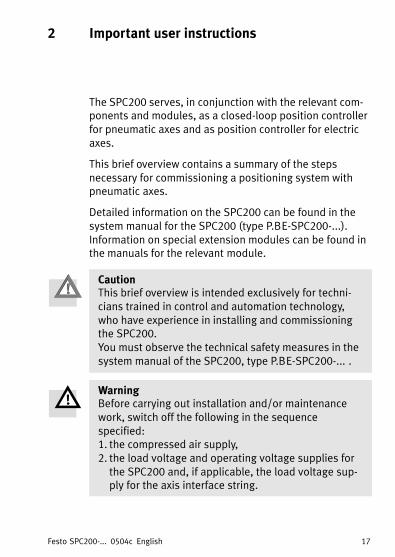
2 Important user instructions
The SPC200 serves, in conjunction with the relevant com�ponents and modules, as a closed−loop position controllerfor pneumatic axes and as position controller for electricaxes.
This brief overview contains a summary of the steps
necessary for commissioning a positioning system withpneumatic axes.
Detailed information on the SPC200 can be found in the
system manual for the SPC200 (type P.BE−SPC200−...).Information on special extension modules can be found inthe manuals for the relevant module.
CautionThis brief overview is intended exclusively for techni�cians trained in control and automation technology,who have experience in installing and commissioningthe SPC200.You must observe the technical safety measures in the
system manual of the SPC200, type P.BE−SPC200−... .
WarningBefore carrying out installation and/or maintenance
work, switch off the following in the sequence
specified:1. the compressed air supply,2. the load voltage and operating voltage supplies forthe SPC200 and, if applicable, the load voltage sup�ply for the axis interface string.
Festo SPC200−... 0504c English18
3 Installation instructions for pneumatic axes
3.1 System overview
POWERDIAGOUTPUT
PNP0 1
INPUT/OUTPUT
INPUT0 1
1
2
3
4
5
6
7
8
7
7
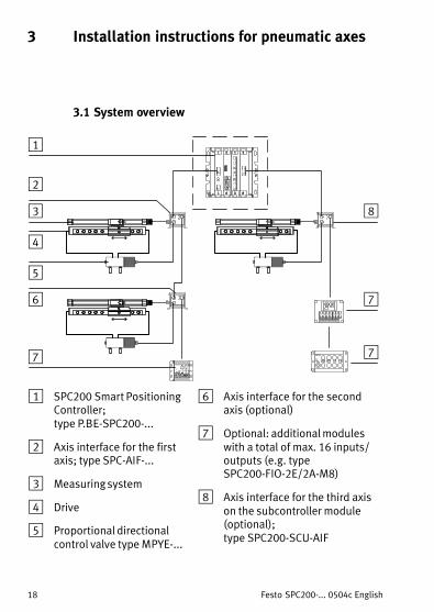
1 SPC200 Smart PositioningController; type P.BE−SPC200−...
2 Axis interface for the firstaxis; type SPC−AIF−...
3 Measuring system
4 Drive
5 Proportional directionalcontrol valve type MPYE−...
6 Axis interface for the secondaxis (optional)
7 Optional: additional moduleswith a total of max. 16 inputs/outputs (e.g. typeSPC200−FIO−2E/2A−M8)
8 Axis interface for the third axison the subcontroller module(optional); type SPC200−SCU−AIF
Festo SPC200−... 0504c English 19
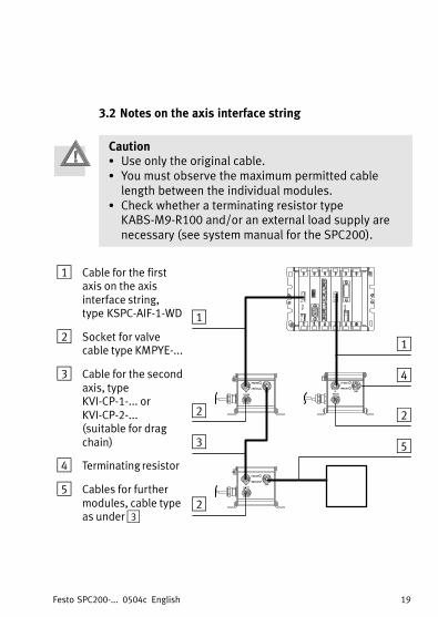
3.2 Notes on the axis interface string
CautionS Use only the original cable.S You must observe the maximum permitted cablelength between the individual modules.
S Check whether a terminating resistor typeKABS−M9−R100 and/or an external load supply arenecessary (see system manual for the SPC200).
1 Cable for the firstaxis on the axisinterface string,type�KSPC−AIF−1−WD
2 Socket for valvecable type KMPYE−...
3 Cable for the secondaxis, typeKVI−CP−1−... orKVI−CP−2−... (suitable for dragchain)
4 Terminating resistor
5 Cables for furthermodules, cable typeas under 3
1
2
3
4
2
2
1
5
Festo SPC200−... 0504c English20
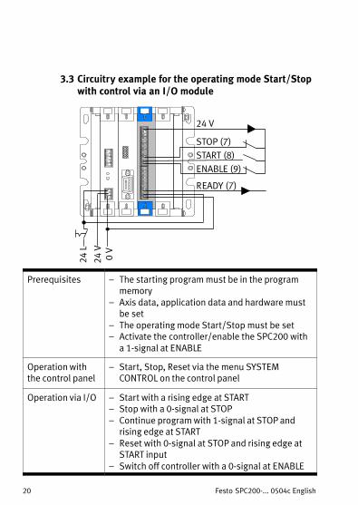
3.3 Circuitry example for the operating mode Start/Stopwith control via an I/O module
START (8)STOP (7)
READY (7)
24 V
ENABLE (9)
0 V
24 V
24 L
Prerequisites � The starting program must be in the programmemory
� Axis data, application data and hardware mustbe set
� The operating mode Start/Stop must be set� Activate the controller/enable the SPC200 with
a 1−signal at ENABLE
Operation withthe control panel
� Start, Stop, Reset via the menu SYSTEMCONTROL on the control panel
Operation via I/O � Start with a rising edge at START� Stop with a 0−signal at STOP
� Continue program with 1−signal at STOP andrising edge at START
� Reset with 0−signal at STOP and rising edge atSTART input
� Switch off controller with a 0−signal at ENABLE
Festo SPC200−... 0504c English 21
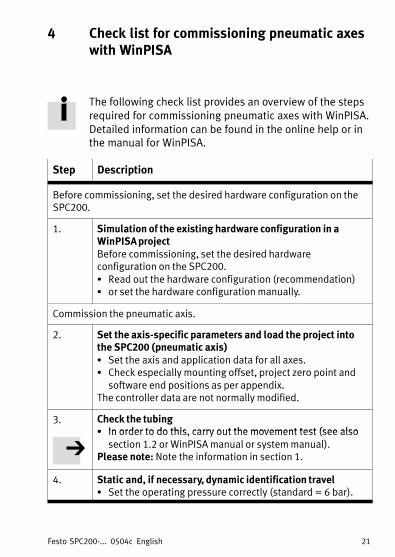
4 Check list for commissioning pneumatic axeswith WinPISA
The following check list provides an overview of the steps
required for commissioning pneumatic axes with WinPISA.Detailed information can be found in the online help or inthe manual for WinPISA.
Step Description
Before commissioning, set the desired hardware configuration on theSPC200.
1. Simulation of the existing hardware configuration in aWinPISA projectBefore commissioning, set the desired hardwareconfiguration on the SPC200.S Read out the hardware configuration (recommendation)S or set the hardware configuration manually.
Commission the pneumatic axis.
2. Set the axis−specific parameters and load the project intothe SPC200 (pneumatic axis)S Set the axis and application data for all axes.S Check especially mounting offset, project zero point and
software end positions as per appendix.The controller data are not normally modified.
3. Check the tubingS In order to do this carry out the movement test (see alsoS In order to do this, carry out the movement test (see also
section 1.2 or WinPISA manual or system manual).Please note: Note the information in section 1.
4. Static and, if necessary, dynamic identification travelS Set the operating pressure correctly (standard = 6 bar).
Festo SPC200−... 0504c English22
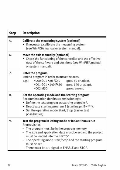
Step Description
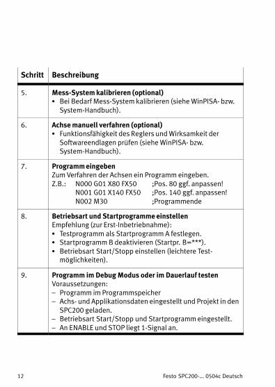
5. Calibrate the measuring system (optional)S If necessary, calibrate the measuring system
(see WinPISA manual or system manual).
6. Move the axis manually (optional)S Check the functioning of the controller and the effective�
ness of the software end positions (see WinPISA manualor system manual).
7. Enter the programEnter a program in order to move the axes.e.g.: N000 G01 X80 FX50 ;pos. 80 or adapt.
N001 G01 X140 FX50 ;pos. 140 or adapt.N002 M30 ;program end
8. Set the operating mode and the starting programRecommendation (for first commissioning):S Define the test program as starting program A.S Deactivate starting program B (starting pr. B=***).S Set the operating mode Start/Stop (easier test
possibilities).
9. Test the program in Debug mode or in Continuous runPrerequisites:� The program must be in the program memory� The axis and application data must be set and the project
must be loaded into the SPC200.� The operating mode Start/Stop and the starting program
must be set.� There must be a 1−signal at ENABLE and STOP.
Festo SPC200−... 0504c Español 23
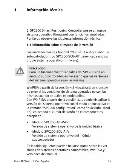
1 Información técnicaEspañol
El SPC200 Smart Positioning Controller posee un nuevosistema operativo (firmware) con funciones ampliadas. Por favor, observe las siguiente información técnica.
1.1 Información sobre el estado de la versión
Las unidades básicas tipo SPC200−CPU−4 o −6 y el módulosubcontrolador tipo SPC200−SCU−AIF tienen cada uno supropio sistema operativo (firmware).
PrecauciónPara un funcionamiento sin fallos del SPC200 con un
módulo subcontrolador, es necesario que las versiones
del sistema operativo sean las mismas.
WinPISA a partir de la versión 4.3 visualizará un mensajede error si las versiones de sistema operativo no son las
mismas cuando se active el modo online. Con WinPISA, a partir de la versión 4.1, puede visualizar laversión del sistema operativo con el modo online activo en
la ventana �SPC200 configuration" como �quickinfo" (tooltip), colocando el cursor del ratón en el componentes
apropiado.
S Módulo SPC200−AIF−PWR:Versión de sistema operativo de la unidad básica
S Módulo SPC200−SCU−AIF:Versión de sistema operativo del módulosubcontrolador
En la tabla siguiente pueden hallarse notas sobre las ver�siones de sistemas operativos compatibles, WinPISA yversiones del manual.
Festo SPC200−... 0504c Español24
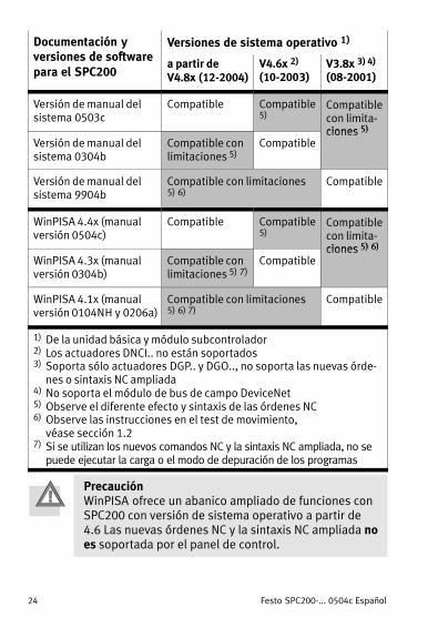
Documentación yversiones de software
Versiones de sistema operativo 1)
versiones de softwarepara el SPC200
a partir deV4.8x (12−2004)
V4.6x 2)
(10−2003)V3.8x 3) 4)
(08−2001)
Versión de manual delsistema 0503c
Compatible Compatible5)
Compatiblecon limita�ciones 5)
Versión de manual delsistema 0304b
Compatible conlimitaciones 5)
Compatibleciones 5)
Versión de manual delsistema 9904b
Compatible con limitaciones 5) 6)
Compatible
WinPISA 4.4x (manualversión 0504c)
Compatible Compatible5)
Compatiblecon limita�ciones 5) 6)
WinPISA 4.3x (manualversión 0304b)
Compatible conlimitaciones 5) 7)
Compatibleciones 5) 6)
WinPISA 4.1x (manualversión 0104NH y 0206a)
Compatible con limitaciones 5) 6) 7)
Compatible
1) De la unidad básica y módulo subcontrolador2) Los actuadores DNCI.. no están soportados3) Soporta sólo actuadores DGP.. y DGO.., no soporta las nuevas órde�
nes o sintaxis NC ampliada4) No soporta el módulo de bus de campo DeviceNet5) Observe el diferente efecto y sintaxis de las órdenes NC6) Observe las instrucciones en el test de movimiento,
véase sección 1.27) Si se utilizan los nuevos comandos NC y la sintaxis NC ampliada, no se
puede ejecutar la carga o el modo de depuración de los programas
PrecauciónWinPISA ofrece un abanico ampliado de funciones conSPC200 con versión de sistema operativo a partir de4.6 Las nuevas órdenes NC y la sintaxis NC ampliada noes soportada por el panel de control.
Festo SPC200−... 0504c Español 25
AtenciónLos fallos en la parametrización pueden causar lesiones
a personas y daños a la propiedad si se suministra una
señal 1 en la entrada ENABLE del control.Habilite el controlador sólo si el sistema de ejes estácorrectamente instalado y parametrizado.
1.2 Notas sobre el movimiento de prueba
AtenciónEl controlador se desconecta durante el movimiento de
prueba. Esto es para evitar que los ejes neumáticos
realizan movimientos bruscos incontrolados cuando seaplica la presión de alimentación. Las posiciones finales
establecidas por software quedan sin efecto.Si desea realizar el movimiento de prueba con la pre�sión de alimentación conectada:S Asegurarse de que todo el margen de posicionado delos ejes neumáticos está libre.
S Advierta del peligro a las demás personas por mediode signos de advertencia adecuados o pantallasprotectoras.
S Mantenga las fuerzas de aceleración a un nivel bajo.Para ello ajuste una presión de alimentación baja deun máximo de 3�bar y retire la carga de trabajo y lacarga de la herramienta.
Observe las siguientes instrucciones al realizar el movi�miento de prueba con una versión diferente de sistemaoperativo en el SPC200 y versiones diferentes de WinPISA.
Festo SPC200−... 0504c Español26
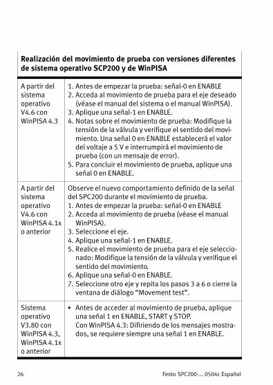
Realización del movimiento de prueba con versiones diferentesde sistema operativo SCP200 y de WinPISA
A partir delsistema
operativoV4.6 con
WinPISA 4.3
1. Antes de empezar la prueba: señal−0 en ENABLE2. Acceda al movimiento de prueba para el eje deseado
(véase el manual del sistema o el manual WinPISA).3. Aplique una señal−1 en ENABLE.4. Notas sobre el movimiento de prueba: Modifique la
tensión de la válvula y verifique el sentido del movi�miento. Una señal 0 en ENABLE establecerá el valordel voltaje a 5 V e interrumpirá el movimiento deprueba (con un mensaje de error).
5. Para concluir el movimiento de prueba, aplique unaseñal 0 en ENABLE.
A partir delsistema
operativoV4.6 con
WinPISA 4.1xo anterior
Observe el nuevo comportamiento definido de la señaldel SPC200 durante el movimiento de prueba.1. Antes de empezar la prueba: señal−0 en ENABLE2. Acceda al movimiento de prueba (véase el manual
WinPISA).3. Seleccione el eje.4. Aplique una señal−1 en ENABLE.5. Realice el movimiento de prueba para el eje seleccio�
nado: Modifique la tensión de la válvula y verifique elsentido del movimiento.
6. Aplique una señal−0 en ENABLE.7. Seleccione otro eje y repita los pasos 3 a 6 o cierre la
S Antes de acceder al movimiento de prueba, apliqueuna señal 1 en ENABLE, START y STOP. Con WinPISA 4.3: Difiriendo de los mensajes mostra�dos, se requiere siempre una señal 1 en ENABLE.
Festo SPC200−... 0504c Español 27
2 Instrucciones importantes para el usuario
El SPC200 sirve, junto con los correspondientes módulos ycomponentes, como regulador de posición en bucle ce�rrado para ejes neumáticos y como regulador de posición
para ejes eléctricos.
Este breve compendio contiene un resumen de los pasos
necesarios para poner a punto un sistema de posicionadocon ejes neumáticos.
Puede hallarse información detallada sobre el SPC200 en
el manual del sistema para el SPC200 (tipo P.BE−SPC200−...). La información sobre los módulos especialesde ampliación puede hallarla en los manuales de los mó�dulos correspondientes.
PrecauciónEste manual está destinado exclusivamente a técnicos
con formación en las tecnologías de control y automati�zación, que posean experiencia en la instalación ypuesta a punto del SPC200.Deberá observar las medidas de seguridad que se
indican en el manual del sistema SPC200, tipoP.BE−SPC200−...�.
AtenciónAntes de proceder con la instalación y/o trabajos de
mantenimiento, desconectar las siguientes fuentes de
potencia en la secuencia indicada:1. la alimentación de la presión del aire2. la tensión de carga y la tensión de funcionamientopara el SPC200 y, si es aplicable, la alimentación dela tensión de carga para el ramal del interface del eje.
Festo SPC200−... 0504c Español28
3 Instrucciones de instalación para ejesneumáticos
3.1 Resumen del sistema
POWERDIAGOUTPUT
PNP0 1
INPUT/OUTPUT
INPUT0 1
1
2
3
4
5
6
7
8
7
7
1 SPC200 Smart PositioningController; tipo P.BE−SPC200−...
2 Interface de ejes para elprimer eje; tipo SPC−AIF−...
3 Sistema de medición
4 Actuador
5 Válvula distribuidora decontrol proporcional tipo MPYE−...
6 Interface de ejes para elsegundo eje (opcional)
7 Opcional: módulos adicionalescon un total de máx. 16 inputs/outputs (p. ej. tipoSPC200−FIO−2E/2A−M8)
8 Interface de ejes para el tercereje en el módulosubcontrolador (opcional); tipo SPC200−SCU−AIF
Festo SPC200−... 0504c Español 29
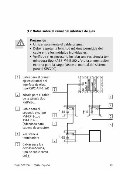
3.2 Notas sobre el ramal del interface de ejes
PrecauciónS Utilizar solamente el cable original.S Debe respetar la longitud máxima permitida del
cable entre los módulos individuales.S Verifique si es necesario instalar una resistencia ter�
minadora tipo KABS−M9−R100 y/o una alimentaciónexterna para la carga (véase el manual del sistemapara el SPC200).
1 Cable para el primereje en el ramal delinterface de ejes,tipo KSPC−AIF−1−WD
2 Zócalo para el cablede la válvula tipoKMPYE−...
3 Cable para elsegundo eje, tipoKVI−CP−1−... oKVI−CP−2−...(adecuado paracadena de arrastre)
4 Resistenciaterminadora
5 Cables para losdemás módulos,tipo de cable comoen 3
1
2
3
4
2
2
1
5
Festo SPC200−... 0504c Español30
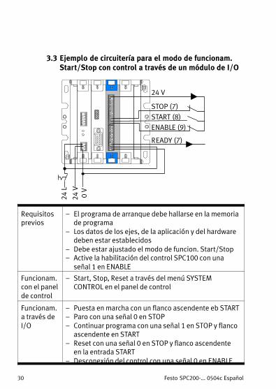
3.3 Ejemplo de circuitería para el modo de funcionam.Start/Stop con control a través de un módulo de I/O
START (8)STOP (7)
READY (7)
24 V
ENABLE (9)
0 V
24 V
24 L
Requisitosprevios
� El programa de arranque debe hallarse en la memoriade programa
� Los datos de los ejes, de la aplicación y del hardwaredeben estar establecidos
� Debe estar ajustado el modo de funcion. Start/Stop� Active la habilitación del control SPC100 con una
señal 1 en ENABLE
Funcionam.con el panelde control
� Start, Stop, Reset a través del menú SYSTEMCONTROL en el panel de control
Funcionam.a través de
I/O
� Puesta en marcha con un flanco ascendente eb START� Paro con una señal 0 en STOP
� Continuar programa con una señal 1 en STOP y flancoascendente en START
� Reset con una señal 0 en STOP y flanco ascendenteen la entrada START
� Desconexión del control con una señal 0 en ENABLE
Festo SPC200−... 0504c Español 31
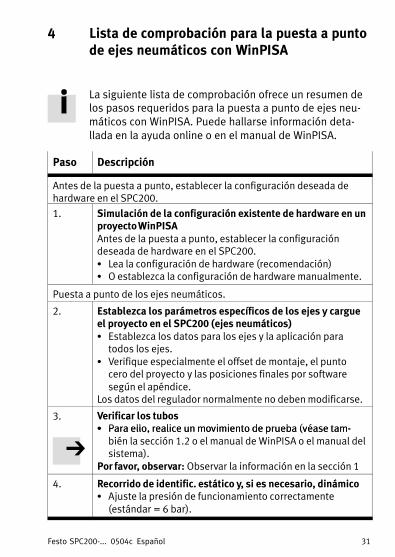
4 Lista de comprobación para la puesta a puntode ejes neumáticos con WinPISA
La siguiente lista de comprobación ofrece un resumen delos pasos requeridos para la puesta a punto de ejes neu�máticos con WinPISA. Puede hallarse información deta�llada en la ayuda online o en el manual de WinPISA.
Paso Descripción
Antes de la puesta a punto, establecer la configuración deseada dehardware en el SPC200.
1. Simulación de la configuración existente de hardware en unproyecto WinPISAAntes de la puesta a punto, establecer la configuracióndeseada de hardware en el SPC200.S Lea la configuración de hardware (recomendación)S O establezca la configuración de hardware manualmente.
Puesta a punto de los ejes neumáticos.
2. Establezca los parámetros específicos de los ejes y cargueel proyecto en el SPC200 (ejes neumáticos)S Establezca los datos para los ejes y la aplicación para
todos los ejes.S Verifique especialmente el offset de montaje, el punto
cero del proyecto y las posiciones finales por softwaresegún el apéndice.
Los datos del regulador normalmente no deben modificarse.
3. Verificar los tubosS Para ello, realice un movimiento de prueba (véase tam�S Para ello, realice un movimiento de prueba (véase tam�
bién la sección 1.2 o el manual de WinPISA o el manual delsistema).
Por favor, observar: Observar la información en la sección 1
4. Recorrido de identific. estático y, si es necesario, dinámicoS Ajuste la presión de funcionamiento correctamente
(estándar = 6 bar).
Festo SPC200−... 0504c Español32
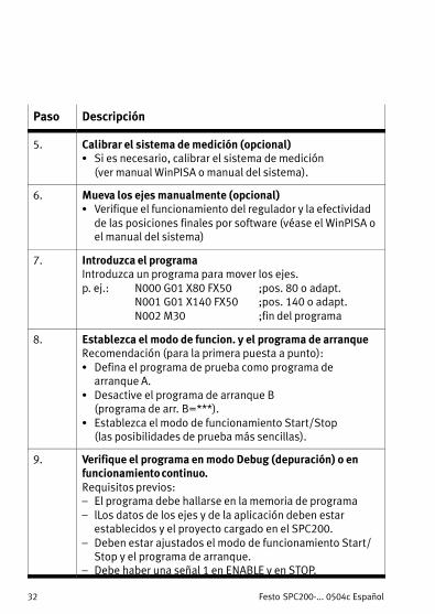
Paso Descripción
5. Calibrar el sistema de medición (opcional)S Si es necesario, calibrar el sistema de medición
(ver manual WinPISA o manual del sistema).
6. Mueva los ejes manualmente (opcional)S Verifique el funcionamiento del regulador y la efectividad
de las posiciones finales por software (véase el WinPISA oel manual del sistema)
7. Introduzca el programaIntroduzca un programa para mover los ejes.p. ej.: N000 G01 X80 FX50 ;pos. 80 o adapt.
N001 G01 X140 FX50 ;pos. 140 o adapt.N002 M30 ;fin del programa
8. Establezca el modo de funcion. y el programa de arranqueRecomendación (para la primera puesta a punto):S Defina el programa de prueba como programa de
arranque A.S Desactive el programa de arranque B
(programa de arr. B=***).S Establezca el modo de funcionamiento Start/Stop
(las posibilidades de prueba más sencillas).
9. Verifique el programa en modo Debug (depuración) o enfuncionamiento continuo.Requisitos previos:� El programa debe hallarse en la memoria de programa
� lLos datos de los ejes y de la aplicación deben estarestablecidos y el proyecto cargado en el SPC200.
� Deben estar ajustados el modo de funcionamiento Start/Stop y el programa de arranque.
� Debe haber una señal 1 en ENABLE y en STOP.
Festo SPC200−... 0504c Français 33
1 Informations Service après−venteFrançais
Le Smart Positioning Controller SPC200 possède un
nouveau système d’exploitation (progiciel) présentant denouvelles fonctions. Tenir compte des informations de
S.A.V. suivantes à ce sujet.
1.1 Informations sur la version
Les unités de base de type SPC200−CPU−4 ou −6 et la cartede sous−contrôleur de type SPC200−SCU−AIF contiennentrespectivement un système d’exploitation (progiciel).
AttentionPour que le SPC200 muni d’une carte de sous−contrô�leur fonctionne parfaitement, il faut que les versions dusystème d’exploitation soient compatibles.
WinPISA, à partir de la version 4.3, affiche un messaged’erreur lors de l’activation du mode en ligne si les ver�sions du système d’exploitation ne sont pas compatibles.Avec WinPISA, à partir de la version 4.1, vous pouvez affi�cher les versions du système d’exploitation en mode en
ligne dans la fenêtre �Configuration SPC200" comme infobrève (Tooltip) en déplaçant le curseur de la souris sur lacarte concernée :
S Carte SPC200−AIF−PWR :Version du système d’exploitation de l’unité de base
S Carte SPC200−SCU−AIF :Version du système d’exploitation de la carte du sous−contrôleur.
Le tableau ci−dessous contient des informations quant à lacompatibilité des versions du système d’exploitation, deWinPISA et du manuel d’utilisation.
Festo SPC200−... 0504c Français34
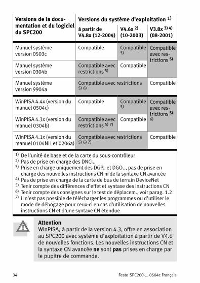
Versions de la docu�mentation et du logiciel
Versions du système d’exploitation 1)
mentation et du logicieldu SPC200
à partir deV4.8x (12−2004)
V4.6x 2)
(10−2003)V3.8x 3) 4)
(08−2001)
Manuel système version 0503c
Compatible Compatible5)
Compatibleavec res�trictions 5)
Manuel système version 0304b
Compatible avecrestrictions 5)
Compatibletrictions 5)
Manuel système version 9904a
Compatible avec restrictions5) 6)
Compatible
WinPISA 4.4x (version dumanuel 0504c)
Compatible Compatible5)
Compatibleavec res�trictions 5)
WinPISA 4.3x (version dumanuel 0304b)
Compatible avecrestrictions 5) 7)
Compatibletrictions 5)6)
WinPISA 4.1x (version dumanuel 0104NH et 0206a)
Compatible avec restrictions5) 6) 7)
Compatible
1) De l’unité de base et de la carte du sous−contrôleur2) Pas de prise en charge des DNCI..3) Prise en charge uniquement des DGP.. et DGO.., pas de prise en
charge des nouvelles instructions CN ni de la syntaxe CN avancée4) Pas de prise en charge de la carte de bus de terrain DeviceNet5) Tenir compte des différences d’effet et syntaxe des instructions CN6) Tenir compte des consignes sur le test de déplacem., voir parag. 1.27) Il n’est pas possible de télécharger les programmes ou d’utiliser le
mode de débogage pour ceux−ci en cas d’utilisation de nouvellesinstructions CN et d’une syntaxe CN étendue
AttentionWinPISA, à partir de la version 4.3, offre en associationau SPC200 avec système d’exploitation à partir de V4.6de nouvelles fonctions. Les nouvelles instructions CN etla syntaxe CN avancée ne sont pas prises en charge parle pupitre de commande.
Festo SPC200−... 0504c Français 35
AvertissementDes erreurs lors du paramétrage peuvent provoquerdes blessures ou des dommages matériels si vous libé�rez le régulateur par un signal 1 sur l’entrée ENABLE.Ne libérer le régulateur que lorsque le système d’axes aété installé et paramétré de façon correcte.
1.2 Consignes relatives au test de déplacement
AvertissementLe régulateur est éteint au cours du test de déplace�ment. Les axes pneumatiques peuvent donc lorsque lapression d’alimentation est présente, se mettre enmouvement de façon involontaire et incontrôlée. Les
fins de course logicielles sont sans effet.Pour effectuer le test de déplacement avec la pressiond’alimentation en marche :S S’assurer que toute la zone de déplacement des axespneumatiques est dégagée.
S Informer également les personnes qui se trouvent horsde cette zone de ce risque en apposant des panneauxd’avertissement correspondants ou des barrières.
S Maintenir les accélérations aussi faibles que possi�ble. Pour ce faire, régler une faible pression d’alimen�tation de 3�bar maximum et retirer la charge utile etla charge d’outillage.
Tenir compte des consignes suivantes lors de l’exécution
du test de déplacement avec les différentes versions desystème d’exploitation du SPC200 et de WinPISA.
Festo SPC200−... 0504c Français36
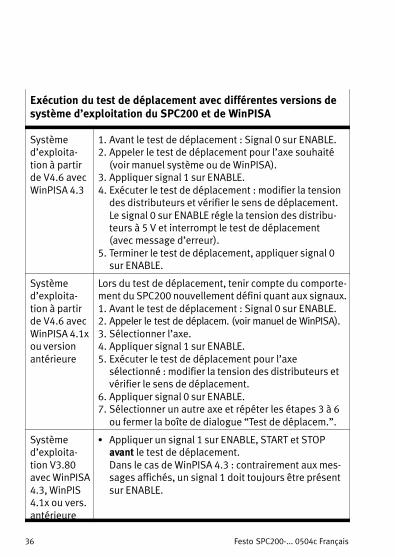
Exécution du test de déplacement avec différentes versions desystème d’exploitation du SPC200 et de WinPISA
Systèmed’exploita�tion à partirde V4.6 avec
WinPISA 4.3
1. Avant le test de déplacement : Signal 0 sur ENABLE.2. Appeler le test de déplacement pour l’axe souhaité
(voir manuel système ou de WinPISA).3. Appliquer signal 1 sur ENABLE.4. Exécuter le test de déplacement : modifier la tension
des distributeurs et vérifier le sens de déplacement.Le signal 0 sur ENABLE régle la tension des distribu�teurs à 5 V et interrompt le test de déplacement(avec message d’erreur).
5. Terminer le test de déplacement, appliquer signal 0sur ENABLE.
Systèmed’exploita�tion à partirde V4.6 avec
WinPISA 4.1xou version
antérieure
Lors du test de déplacement, tenir compte du comporte�ment du SPC200 nouvellement défini quant aux signaux.1. Avant le test de déplacement : Signal 0 sur ENABLE.2. Appeler le test de déplacem. (voir manuel de WinPISA).3. Sélectionner l’axe.4. Appliquer signal 1 sur ENABLE.5. Exécuter le test de déplacement pour l’axe
sélectionné : modifier la tension des distributeurs etvérifier le sens de déplacement.
6. Appliquer signal 0 sur ENABLE.7. Sélectionner un autre axe et répéter les étapes 3 à 6
ou fermer la boîte de dialogue �Test de déplacem.".
Systèmed’exploita�tion V3.80avec WinPISA4.3, WinPIS4.1x ou vers.antérieure
S Appliquer un signal 1 sur ENABLE, START et STOPavant le test de déplacement. Dans le cas de WinPISA 4.3 : contrairement aux mes�sages affichés, un signal 1 doit toujours être présentsur ENABLE.
Festo SPC200−... 0504c Français 37
2 Instructions d’utilisation
En association aux cartes et modules appropriés, leSPC200 est conçu pour la commande de positionnementet la régulation de position pour les axes pneumatiques
ainsi que la commande de positionnement pour les axesélectriques.
Cette notice simplifiée contient un résumé des étapesnécessaires à la mise en service d’un système de position�nement avec axes pneumatiques.
Pour de plus amples informations sur le SPC200, se repor�ter au manuel système du SPC200 (type P.BE−SPC200−...).Vous trouverez des informations sur les cartes d’extension
dans les manuels d’utilisation des cartes en question.
AttentionCette notice simplifiée est destinée aux spécialistes des
techniques de commande et d’automatisation possé�dant déjà une certaine expérience dans l’installation etla mise en service du SPC200.Tenir impérativement compte des consignes de sécuritécontenues dans le manuel système du SPC200, typeP.BE−SPC200−...�.
AvertissementAvant tous travaux d’entretien et d’installation, couperles sources d’énergie suivantes dans l’ordre indiqué :1. Alimentation en air comprimé2. Tensions de puissance et de commande sur le
SPC200 et, le cas échéant, tension de puissance surla branche d’interface d’axe.
Festo SPC200−... 0504c Français38
3 Consignes d’installation de l’axe pneumatique
3.1 Présentation du système
POWERDIAGOUTPUT
PNP0 1
INPUT/OUTPUT
INPUT0 1
1
2
3
4
5
6
7
8
7
7
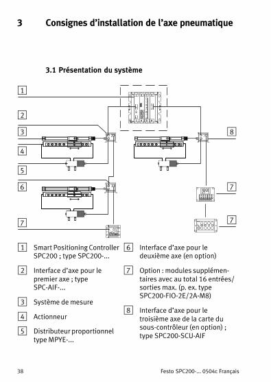
1 Smart Positioning ControllerSPC200 ; type SPC200−...
2 Interface d’axe pour lepremier axe ; typeSPC−AIF−...
3 Système de mesure
4 Actionneur
5 Distributeur proportionneltype MPYE−...
6 Interface d’axe pour ledeuxième axe (en option)
7 Option : modules supplémen�taires avec au total 16 entrées/sorties max. (p. ex. typeSPC200−FIO−2E/2A−M8)
8 Interface d’axe pour letroisième axe de la carte dusous−contrôleur (en option) ;type SPC200−SCU−AIF
Festo SPC200−... 0504c Français 39
3.2 Consignes relatives à la branche d’interface d’axe
AttentionS Utiliser uniquement un câble d’origine.S Tenir impérativement compte de la longueur maxi�
mum autorisée du câble entre les différents modules.S Vérifier si une résistance de terminaison de typeKABS−M9−R100 et/ou une alimentation externe sontnécessaires (voir le manuel système du SPC200).
1 Câble pour lepremier axe sur labranche d’interfaced’axe, typeKSPC−AIF−1−WD
2 Connecteur femellepour le câble dedistributeur detype�KMPYE−...
3 Câble pour ledeuxième axe,type�KVI−CP−1−... ouKVI−CP−2−... (souple)
4 Résistance determinaison
5 Câble pour d’autresmodules, type decâble, voir rep. 3
1
2
3
4
2
2
1
5
Festo SPC200−... 0504c Français40
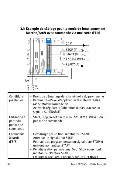
3.3 Exemple de câblage pour le mode de fonctionnementMarche/Arrêt avec commande via une carte d’E/S
START (8)STOP (7)
READY (7)
24 V
ENABLE (9)
0 V
24 V
24 L
Conditionspréalables
� Progr. de démarrage dans la mémoire du programme� Paramètres d’axe, d’application et matériel réglés
� Mode Marche/Arrêt activé� Activer le régulateur/Libération du SPC200 par un
signal 1 sur ENABLE
Utilisation àpartir dupupitre decommande
� Start, Stop, Reset par le menu SYSTEM CONTROL dupupitre de commande
Commandeà partird’E/S
� Démarrage par un front montant sur START� Arrêt par un signal 0 sur STOP
� Poursuite du programme par un signal 1 sur STOP etun front montant sur START
� Réinitialisation par un signal 0 sur STOP et un frontmontant sur l’entrée START
� Eteindre le régulateur par un signal 0 sur ENABLE
Festo SPC200−... 0504c Français 41
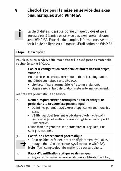
4 Check−liste pour la mise en service des axespneumatiques avec WinPISA
La check−liste ci−dessous donne un aperçu des étapes
nécessaires à la mise en service des axes pneumatiques
avec WinPISA. Pour de plus amples informations, se repor�ter à l’aide en ligne ou au manuel d’utilisation de WinPISA.
Etape Description
Pour la mise en service, définir tout d’abord la configuration matériellesouhaitée sur le SPC200.
1. Copier la configuration matérielle existante dans un projetWinPISAPour la mise en service, créer tout d’abord la configurationmatérielle souhaitée sur le SPC200.S Lire la configuration matérielle (recommandation).S Ou paramétrer la configuration matérielle manuellement.
Mettre l’axe pneumatique en service.
2. Définir les paramètres spécifiques à l’axe et charger leprojet dans le SPC200 (axe pneumatique)S Définir les paramètres d’axe et d’application pour tous les
axes.S Vérifier particulièrement le décalage d’origine, le point
zéro du projet et les fins de course logicielle par rapport àl’installation.
D’une manière générale, les paramètres du régulateur nesont pas modifiés.
3. Contrôle du branchement pneumatiquef é l d dé l (
p qS Pour ce faire, exécuter le test de déplacement (voir aussi
paragraphe 1.2 ou le manuel système ou de WinPISA).Note : Tenir compte des informations du paragraphe 1.
4. Passe d’identification statique ou dynamiqueS Régler correctement la pression de service (standard = 6 bar).
Festo SPC200−... 0504c Français42
Etape Description
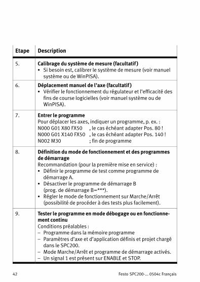
5. Calibrage du système de mesure (facultatif )S Si besoin est, calibrer le système de mesure (voir manuel
système ou de WinPISA).
6. Déplacement manuel de l’axe (facultatif )S Vérifier le fonctionnement du régulateur et l’efficacité des
fins de course logicielles (voir manuel système ou deWinPISA).
7. Entrer le programmePour déplacer les axes, indiquer un programme, p. ex. :N000 G01 X80 FX50 , le cas échéant adapter Pos. 80 !N000 G01 X140 FX50 , le cas échéant adapter Pos. 140 !N002 M30 ; fin de programme
8. Définition du mode de fonctionnement et des programmesde démarrageRecommandation (pour la première mise en service) :S Définir le programme de test comme programme de
démarrage A.S Désactiver le programme de démarrage B
(prog. de démarrage B=***).S Régler le mode de fonctionnement sur Marche/Arrêt
(possibilité de procéder à des tests plus facilement).
9. Tester le programme en mode débogage ou en fonctionne�ment continuConditions préalables :� Programme dans la mémoire programme
� Paramètres d’axe et d’application définis et projet chargédans le SPC200.
� Mode Marche/Arrêt et programme de démarrage activés.� Un signal 1 est présent sur ENABLE et STOP.
Festo SPC200−... 0504c Italiano 43
1 Informazioni di servizioItaliano
Lo Smart Positioning Controller SPC200 è dotato di un
nuovo sistema operativo (firmware) che presenta unagamma di funzioni ampliata. Siete pregati di rispettare leseguenti informazioni di servizio.
1.1 Informazioni sulle versioni
Le unità base tipo SPC200−CPU−4 o SPC200−CPU−6 e il mo�dulo sub−controller tipo SPC200−SCU−AIF sono dotatiognuno di un sistema operativo (firmware) proprio.
AttenzionePer assicurare il perfetto funzionamento dell’SPC200con un modulo sub−controller è indispensabile che irispettivi sistemi operativi siano equivalenti.
Nel caso in cui le versioni dei sistemi operativi non coinci�dano, in WinPISA versione 4.3 e superiori viene visualiz�zato un messaggio di errore al momento dell’attivazionedel modo online. Con WinPISA versione 4.1 e superiori, quando il modoonline è attivato è possibile visualizzare le versioni deisistemi operativi nella finestra �SPC200 configuration"sotto forma di informazioni di guida rapida (Tooltip) spo�stando il puntatore del mouse sul modulo che interessa:
S Modulo SPC200−AIF−PWR:versione del sistema operativo dell’unità base
S Modulo SPC200−SCU−AIF:vers. del sistema operativo del modulo sub−controller.
Nella tabella riportata di seguito sono state raccolte infor�mazioni circa la compatibilità tra le versioni dei sistemioperativi, di WinPISA e dei manuali.
Festo SPC200−... 0504c Italiano44
Versioni documenta�zione e software relativi
Versioni dei sistemi operativi 1)
zione e software relativiall’SPC200
V4.8x e supe�riori (12−2004)
V4.6x 2)
(10−2003)V3.8x 3) 4)
(08−2001)
Manuale di sistemaversione 0503c
Compatibili Compatibili5)
Parzial�mentecompatibili
Manuale di sistemaversione 0304b
Parzialmentecompatibili 5)
Compatibilicompatibili5)
Manuale di sistemaversione 9904a
Parzialmente compatibili 5) 6) Compatibili
WinPISA 4.4x (versione manuale 0504c)
Compatibili Compatibili5)
Parzial�mentecompatibili
WinPISA 4.3x (versione manuale 0304b)
Parzialmentecompatibili 5) 7)
Compatibilicompatibili5) 6)
WinPISA 4.1x (versionimanuale 0104NH e 0206a)
Parzialmente compatibili 5) 6) 7)
Compatibili
1) Dell’unità base e del modulo sub−controller2) Non viene supportato per i attuatori DNCI..3) Vengono supportati solamente gli attuatori DGP.. e DGO..; non ven�
gono invece supportati i nuovi comandi NC e la sintassi NC ampliata.4) Non viene supportato il modulo Fieldbus DeviceNet5) La sintassi dei comandi NC e gli effetti da essi prodotti presentano
delle differenze6) Attenersi alle istruzioni per l’effettuazione del test dinamico riportate
nel Par. 1.27) Caricamento o modo debug di programmi non sono possibili quando
si impiegano nuovi comandi NC e sintassi NC ampliata
AttenzioneIl software WinPISA versione 4.3 e superiori installatosu un SPC200 equipaggiato con sistema operativo ver�sione 4.6 e superiori è in grado di offrire un’ampiagamma di funzioni. I nuovi comandi CN e la sintassi CNampliata non vengono supportati dal quadro operativo.
Festo SPC200−... 0504c Italiano 45
AvvertenzaEventuali errori in fase di parametrizzazione possonodeterminare danni personali o materiali nel momendoin cui si abilita il funzionamento dell’unità di controllomediante l’attivazione di un segnale logico 1 nell’in�gresso ENABLE.Si consiglia pertanto di abilitare l’unità di controllo so�lamente dopo avere installato e parametrizzato a regolad’arte il sistema di assi.
1.2 Istruzioni per l’effettuazione del test dinamico
AvvertenzaDurante il test dinamico, l’unità di controllo è disatti�vata. Tale accorgimento consente di movimentare inmodo controllato e in totale autonomia gli assi pneuma�tici con la pressione di alimentazione inserita. I fine�corsa software impostati sono disattivati. Se si intende effettuare il test dinamico con la pres�sione di alimentazione inserita:S Accertarsi che l’intera area di traslazione degli assipneumatici sia libera.
S Segnalare la presenza di un pericolo anche a personeesterne a tale area, applicando appositi cartelli disegnalazione o installando degli sbarramenti.
S È necessario mantenere le forze di accelerazione alivelli bassi. Si raccomanda pertanto di registrare lapressione di alimentazione su max. 3�bar e di rimuo�vere il carico utile e il carico dell’utensile.
Attenersi rigorosamente alle istruzioni riportate a seguirecirca le differenti modalità esecutive del test dinamico con levarie versioni del sistema operativo dell’SPC200 e di WinPISA.
Festo SPC200−... 0504c Italiano46
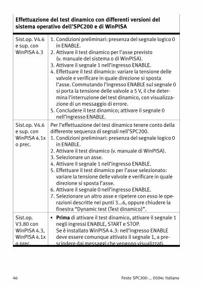
Effettuazione del test dinamico con differenti versioni delsistema operativo dell’SPC200 e di WinPISA
Sist.op. V4.6e sup. con
WinPISA 4.3
1. Condizioni preliminari: presenza del segnale logico 0in ENABLE.
2. Attivare il test dinamico per l’asse previsto (v. manuale del sistema o di WinPISA).
3. Attivare il segnale 1 nell’ingresso ENABLE.4. Effettuare il test dinamico: variare la tensione delle
valvole e verificare in quale direzione si spostal’asse. Commutando l’ingresso ENABLE sul segnale 0si porta la tensione delle valvole a 5 V, il che deter�mina l’interruzione del test dinamico, con visualizza�zione di un messaggio di errore.
5. Concludere il test dinamico; attivare il segnale 0nell’ingresso ENABLE.
Sist.op. V4.6e sup. con
WinPISA 4.1xo prec.
Per l’effettuazione del test dinamico tenere conto delladifferente sequenza di segnali nell’SPC200.1. Condizioni preliminari: presenza del segnale logico 0
in ENABLE.2. Attivare il test dinamico (v. manuale di WinPISA).3. Selezionare un asse.4. Attivare il segnale 1 nell’ingresso ENABLE.5. Effettuare il test dinamico per l’asse selezionato:
variare la tensione delle valvole e verificare in qualedirezione si sposta l’asse.
6. Attivare il segnale 0 nell’ingresso ENABLE.7. Selezionare un altro asse e ripetere con esso le ope�
razioni descritte nei punti 3...6, oppure chiudere lafinestra �Dynamic test (Test dinamico)".
Sist.op.V3.80 con
WinPISA 4.3,WinPISA 4.1xo prec.
S Prima di attivare il test dinamico, attivare il segnale 1negli ingressi ENABLE, START e STOP. Se è installato WinPISA 4.3: nell’ingresso ENABLEdeve essere comunque attivato il segnale 1, a pre�scindere dai messaggi che vengono visualizzati.
Festo SPC200−... 0504c Italiano 47
2 Indicazioni per l’utilizzatore
L’SPC200 collegato ai relativi moduli e unità, è preposto alcontrollo della traslazione e delle posizioni degli assipneumatici nonché al controllo della traslazione degli assielettrici.
Nella presente guida rapida vengono illustrate le opera�zioni necessarie per la messa in servizio di un sistema diposizionamento e degli assi pneumatici.
Per informazioni dettagliate sull’SPC200 si rimanda al ma�nuale di sistema dell’SPC200 (tipo P.BE−SPC200−...). Perinformazioni concernenti moduli di espansione specificifare riferimento alle rispettive descrizioni.
AttenzioneLa presente guida rapida è rivolta esclusivamente atecnici specializzati nelle tecnologie di controllo ed
automazione con esperienza nell’installazione e nellamessa in servizio dell’SPC200.Attenersi rigorosamente alle istruzioni tecniche di sicu�rezza riportate nel manuale di sistema dell’SPC200 tipoP.BE−SPC200−...�.
AvvertenzaPrima di iniziare i lavori di installazione e manuten�zione, scollegare quanto segue nell’ordine indicato:1. alimentazione dell’aria compressa2. alimentazione della tensione di carico e di esercizio
dell’SPC200 nonché ev. alimentazione della tensione
di carico sulla linea di interfacciamento assi.
Festo SPC200−... 0504c Italiano48
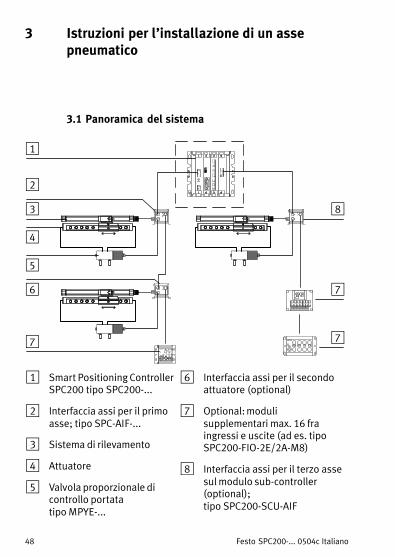
3 Istruzioni per l’installazione di un assepneumatico
3.1 Panoramica del sistema
POWERDIAGOUTPUT
PNP0 1
INPUT/OUTPUT
INPUT0 1
1
2
3
4
5
6
7
8
7
7
1 Smart Positioning ControllerSPC200 tipo SPC200−...
2 Interfaccia assi per il primoasse; tipo SPC−AIF−...
3 Sistema di rilevamento
4 Attuatore
5 Valvola proporzionale dicontrollo portata tipo MPYE−...
6 Interfaccia assi per il secondoattuatore (optional)
7 Optional: modulisupplementari max. 16 fraingressi e uscite (ad es. tipoSPC200−FIO−2E/2A−M8)
8 Interfaccia assi per il terzo assesul modulo sub−controller(optional); tipo SPC200−SCU−AIF
Festo SPC200−... 0504c Italiano 49
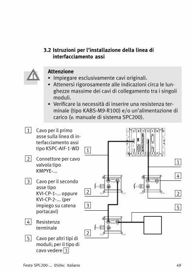
3.2 Istruzioni per l’installazione della linea diinterfacciamento assi
AttenzioneS Impiegare esclusivamente cavi originali.S Attenersi rigorosamente alle indicazioni circa le lun�
ghezze massime dei cavi di collegamento tra i singolimoduli.
S Verificare la necessità di inserire una resistenza ter�minale (tipo KABS−M9−R100) e/o un’alimentazione dicarico (v. manuale di sistema SPC200).
1 Cavo per il primoasse sulla linea di in�terfacciamento assitipo KSPC−AIF−1−WD
2 Connettore per cavovalvola tipoKMPYE−...
3 Cavo per il secondoasse tipoKVI−CP−1−... oppureKVI−CP−2−... (perimpiego su catenaportacavi)
4 Resistenzaterminale
5 Cavo per altri tipi dimoduli; per il tipo dicavo vedere 3
1
2
3
4
2
2
1
5
Festo SPC200−... 0504c Italiano50
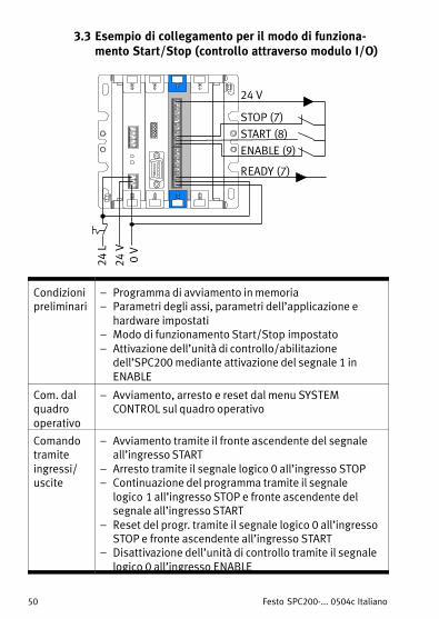
3.3 Esempio di collegamento per il modo di funziona�mento Start/Stop (controllo attraverso modulo I/O)
START (8)STOP (7)
READY (7)
24 V
ENABLE (9)
0 V
24 V
24 L
Condizionipreliminari
� Programma di avviamento in memoria� Parametri degli assi, parametri dell’applicazione e
hardware impostati� Modo di funzionamento Start/Stop impostato� Attivazione dell’unità di controllo/abilitazione
dell’SPC200 mediante attivazione del segnale 1 inENABLE
Com. dalquadrooperativo
� Avviamento, arresto e reset dal menu SYSTEMCONTROL sul quadro operativo
Comandotramiteingressi/uscite
� Avviamento tramite il fronte ascendente del segnaleall’ingresso START
� Arresto tramite il segnale logico 0 all’ingresso STOP� Continuazione del programma tramite il segnale
logico�1 all’ingresso STOP e fronte ascendente delsegnale all’ingresso START
� Reset del progr. tramite il segnale logico 0 all’ingressoSTOP e fronte ascendente all’ingresso START
� Disattivazione dell’unità di controllo tramite il segnalelogico 0 all’ingresso ENABLE
Festo SPC200−... 0504c Italiano 51
4 Check−list per l’effettuazione della messa inservizio degli assi pneumatici con WinPISA
Nella check−list riportata di seguito vengono schematiz�zate le operazioni necessarie per l’effettuazione dellamessa in servizio degli assi pneumatici attraverso WinPISA. Per informazioni dettagliate si rimanda alla fun�zione Help online oppure al manuale del WinPISA.
Operaz. Descrizione
Prima di iniziare la messa in servizio, predisporre nell’SPC200 la confi�gurazione hardware prevista.
1. Riproduzione della configurazione hardware esistente inun progetto WinPISAPrima di iniziare la messa in servizio, predisporrenell’SPC200 la configurazione hardware prevista.S (Si consiglia di) importare la configurazione hardware.S In alternativa, impostare manualm. la configuraz. hardware.
Avviare l’asse pneumatico.
2. Impostazione dei parametri specifici dell’asse e carica�mento della configuraz. nell’SPC200 (asse pneumatico)S Impostare i parametri dell’applicazione e specifici di tutti
gli assi.S Verificare in modo particolare che le origini Offset, le ori�
gini del progetto e i finecorsa software siano impostaticorrettamente in base alle caratteristiche dell’impianto.
Nella norma, in questa fase non è necessario modificare iparametri dell’unità di controllo.
3. Controllo delle tubazioni pneumaticheff l d ( d h
pS Effettuare il test dinamico (vedi anche Par. 1.2 oppure
consultare il manuale WinPISA o di sistema).Nota: Attenersi alle indicazioni riportate al Par. 1.
4. Esecuzione della corsa di riconoscimento statico edeventualmente dinamicoS Registr. una press. di esercizio corretta (val. stand. = 6 bar)
Festo SPC200−... 0504c Italiano52
Operaz. Descrizione
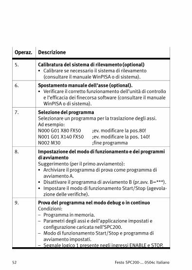
5. Calibratura del sistema di rilevamento (optional)S Calibrare se necessario il sistema di rilevamento
(consultare il manuale WinPISA o di sistema).
6. Spostamento manuale dell’asse (optional).S Verificare il corretto funzionamento dell’unità di controllo
e l’efficacia dei finecorsa software (consultare il manualeWinPISA o di sistema).
7. Selezione del programmaSelezionare un programma per la traslazione degli assi.Ad esempio:N000 G01 X80 FX50 ;ev. modificare la pos.80!N001 G01 X140 FX50 ;ev. modificare la pos. 140!N002 M30 ;fine programma
8. Impostazione del modo di funzionamento e dei programmidi avviamentoSuggerimento (per il primo avviamento):S Archiviare il programma di prova come programma di
avviamento A.S Disattivare il programma di avviamento B (pr.avv. B=***).S Impostare il modo di funzionamento Start/Stop (agevola�
zione delle verifiche).
9. Prova del programma nel modo debug o in continuoCondizioni:� Programma in memoria.� Parametri degli assi e dell’applicazione impostati e
configurazione caricata nell’SPC200.� Modo di funzionamento Start/Stop e programma di
avviamento impostati.� Segnale logico 1 presente negli ingressi ENABLE e STOP.
Festo SPC200−... 0504c Svenska 53
1 ServiceinformationSvenska
Smart Positioning Controller SPC200 har ett nyttoperativsystem (fast programvara) med utökade
funktioner. Läs följande serviceinformation noggrant.
1.1 Versioninformation
Basenheterna av typ SPC200−CPU−4 eller −6 ochsubcontroller−komponenterna av typ SPC200−SCU−AIFinnehåller vardera ett eget operativsystem (fastprogramvara).
FörsiktigtFör att SPC200 ska kunna fungera felfritt med en
subcontroller−komponent är det nödvändigt attoperativsystemversionerna överensstämmer.
När online−läget aktiveras i WinPISA, version 4.3 ochsenare, visas ett felmeddelande om versionerna avoperativsystemen inte överensstämmer. Om du använder WinPISA version 4.1 och senare kan duvisa operativsystemversionerna i online−läge i fönstret�SPC200 Konfiguration" som snabbinfo(funktionsbeskrivning) genom att ställa muspekaren påmotsvarande komponent:
S Komponenten SPC200−AIF−PWR:Basenhetens operativsystemversion
S Komponenten SPC200−SCU−AIF:Subcontroller−komponentens operativsystemversion
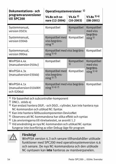
Följande tabell innehåller hänvisningar till kompatiblaoperativsystem−, WinPISA− och manualversioner.
Festo SPC200−... 0504c Svenska54
Dokumentations− ochprogramvaruversioner
Operativsystemversioner 1)
programvaruversionertill SPC200
V4.8x och se�nare (12−2004)
V4.6x 2)
(10−2003)V3.8x 3) 4)
(08−2001)
Systemmanual, version 0503c
Kompatibel Kompatibel5)
Kompatibelmed vissbegräns
Systemmanual, version 0304b
Kompatibel medviss begräns�ning 5)
Kompatibelbegräns�ning 5)
Systemmanual, version 9904a
Kompatibel med viss begräns�ning 5) 6)
Kompatibel
WinPISA 4.4x(manualversion 0504c)
Kompatibel Kompatibel5)
Kompatibelmed vissbegräns
WinPISA 4.3x(manualversion 0304b)
Kompatibel medviss begräns�ning 5) 7)
Kompatibelbegräns�ning 5) 6)
WinPISA 4.1x(manualversion 0104NHoch 0206a)
Kompatibel med viss begräns�ning 5) 6) 7)
Kompatibel
1) För basenhet och subcontroller−komponent2) DNCI.. stöds ej3) Kan endast hantera DGP..− och DGO..−cylinder, kan inte hantera nya
NC−kommandon och utökad NC−Syntax4) Kan inte hantera fältbusskomponenten DeviceNet5) Observera att NC−kommandona har olika effekt och syntax6) Läs anvisningarna till rörelsetestet, se avsnitt 1.27) Vid användning av nya NC−kommandon och utökad NC−syntax
fungerar inte överföring av eller Debug−läge för program
FörsiktigtWinPISA version 4.3 och senare tillhandahåller utökadefunktioner med SPC200 med operativsystemversion 4.6och senare. De nya NC−kommandona och den utökadeNC−syntaxen kan inte hanteras av manöverpanelen.
Festo SPC200−... 0504c Svenska 55
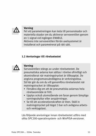
VarningFel vid parametreringen kan leda till personskador ochmateriella skador om du aktiverar servoventilen genom
en 1−signal vid ingången ENABLE.Aktivera inte servoventilen förrän axelsystemet ärinstallerat och parametrerat på rätt sätt.
1.2 Anvisningar till rörelsetestet
VarningServoventilen stängs av under rörelsetestet. De
pneumatiska axlarna kan sättas i rörelse ofrivilligt ochokontrollerat när matningstrycket är tillkopplat. Deangivna programvaruändlägena är verkningslösa.Så här gör du om du vill genomföra rörelsetestet närmatningstrycket är tillkopplat:S Försäkra dig om att de pneumatiska axlarnas helarörelseområde är fritt.
S Upplys också utomstående om faran genom lämpligavarningsskyltar eller avspärrningar.
S Se till att accelerationskraften är liten. Ställ inmatningstrycket på högst 3�bar och avlägsna arbets−och verktygslast.
Läs följande anvisningar innan rörelsetestet utförs medolika SPC200−operativsystem− och WinPISA−versioner.
Festo SPC200−... 0504c Svenska56
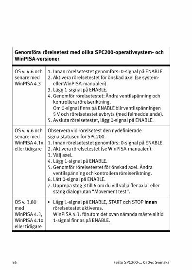
Genomföra rörelsetest med olika SPC200−operativsystem− ochWinPISA−versioner
OS v. 4.6 ochsenare med
WinPISA 4.3
1. Innan rörelsetestet genomförs: 0−signal på ENABLE.2. Aktivera rörelsetestet för önskad axel (se system−
eller WinPISA−manualen).3. Lägg 1−signal på ENABLE.4. Genomför rörelsetestet: Ändra ventilspänning och
kontrollera rörelseriktning. Om 0−signal finns på ENABLE blir ventilspänningen 5 V och rörelsetestet avbryts (med felmeddelande).
5. Avsluta rörelsetestet, lägg 0−signal på ENABLE.
OS v. 4.6 ochsenare med
WinPISA 4.1xeller tidigare
Observera vid rörelsetest den nydefinieradesignalstatusen för SPC200.1. Innan rörelsetestet genomförs: 0−signal på ENABLE.2. Aktivera rörelsetestet (se WinPISA−manualen).3. Välj axel.4. Lägg 1−signal på ENABLE.5. Genomför rörelsetestet för önskad axel: Ändra
ventilspänning och kontrollera rörelseriktning.6. Lätt 0−signal på ENABLE.7. Upprepa steg 3 till 6 om du vill välja fler axlar eller
stäng dialogrutan �Movement test".
OS v. 3.80med WinPISA 4.3,WinPISA 4.1xeller tidigare
S Lägg 1−signal på ENABLE, START och STOP innanrörelsetestet aktiveras. WinPISA 4.3: förutom det ovan nämnda måste alltid1−signal finnas på ENABLE.
Festo SPC200−... 0504c Svenska 57
2 Användaranvisningar
Enligt anvisningarna är SPC200, tillsammans medtillhörande komponenter och moduler, avsedd förpositionering och lägesreglering av pneumatiska axlarsamt för positionering av elektriska axlar.
Den här översikten innehåller en sammanfattning av detsom krävs för att ta ett positioneringssystem medpneumatiska axlar i drift.
Mer utförlig information om SPC200 finns isystemmanualen till SPC200 (typ P.BE−SPC200−...).Information om särskilda utökningskomponenter finns ibeskrivningen till respektive komponent.
FörsiktigtDen här översikten vänder sig till utbildad personalinom styr− och reglerteknik som har erfarenhet avinstallation och idrifttagning av SPC200.Följ de säkerhetstekniska anvisningarna isystemmanualen till SPC200, typ P.BE−SPC200−... .
VarningKoppla från följande i angiven ordningsföljd innan
installations− eller underhållsarbete utförs:1. Tryckluftsmatning2.Matnings− och driftspänning för SPC200 och
matningsspänning för axelgränssnittsslinga, om
sådan finns.
Festo SPC200−... 0504c Svenska58
3 Installationsanvisningar för pneumatisk axel
3.1 Systemöversikt
POWERDIAGOUTPUT
PNP0 1
INPUT/OUTPUT
INPUT0 1
1
2
3
4
5
6
7
8
7
7
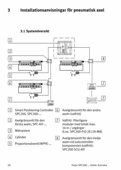
1 Smart Positioning ControllerSPC200, SPC200−...
2 Axelgränssnitt för denförsta axeln; SPC−AIF−...
3 Mätsystem
4 Cylinder
5 Proportionalventil MPYE−...
6 Axelgränssnitt för den andraaxeln (valfritt)
7 Valfritt: Ytterligare moduler med totalt max. 16 in−/ utgångar (t.ex. SPC200−FIO−2E/2A−M8)
8 Axelgränssnitt för den tredjeaxeln vid subcontroller−komponenten (valfritt):SPC200−SCU−AIF
Festo SPC200−... 0504c Svenska 59
3.2 Anvisningar för axelgränssnittslingan
FörsiktigtS Använd endast originalkablar.S Observera högsta tillåtna kabellängd mellan de
enskilda modulerna.S Kontrollera om det krävs ett termineringsmotstånd,typ KABS−M9−R100, och/eller en externmatningsspänning (se systemmanualen SPC200).
1 Kabel för den förstaaxeln påaxelgränssnittslingan,KSPC−AIF−1−WD
2 Uttag för ventilkabel,KMPYE−...
3 Kabel för den andraaxeln, KVI−CP−1−...eller KVI−CP−2−... (för kabelsläpkedja)
4 Terminerings−motstånd
5 Kabel för ytterligaremoduler, kabeltypsom nedan 3
1
2
3
4
2
2
1
5
Festo SPC200−... 0504c Svenska60
3.3 Kopplingsexempel för driftsättet start/stopp medstyrning via en I/O−enhet
START (8)STOP (7)
READY (7)
24 V
ENABLE (9)
0 V
24 V
24 L
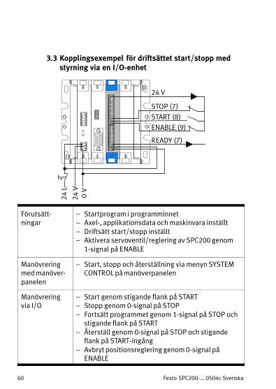
Förutsätt−ningar
� Startprogram i programminnet� Axel−, applikationsdata och maskinvara inställt� Driftsätt start/stopp inställt� Aktivera servoventil/reglering av SPC200 genom
1−signal på ENABLE
Manövreringmed manöver−panelen
� Start, stopp och återställning via menyn SYSTEMCONTROL på manöverpanelen
Manövreringvia I/O
� Start genom stigande flank på START� Stopp genom 0−signal på STOP
� Fortsätt programmet genom 1−signal på STOP ochstigande flank på START
� Återställ genom 0−signal på STOP och stigandeflank på START−ingång
� Avbryt positionsreglering genom 0−signal påENABLE
Festo SPC200−... 0504c Svenska 61
4 Checklista för idrifttagning av pneumatiskaaxlar med WinPISA
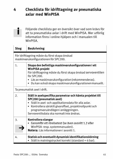
Följande checklista ger en översikt över vad som krävs föratt ta pneumatiska axlar i drift med WinPISA. Mer utförliginformation finns i online−hjälpen och i manualen tillWinPISA.
Steg Beskrivning
För idrifttagning måste du först skapa önskadmaskinvarukonfigurationen för SPC200.
1. Skapa den befintliga maskinvarukonfigurationen i ettWinPISA−projektFör idrifttagning måste du först skapa önskad servoventilenför SPC200.S Läs av maskinvarukonfiguration (rekommenderas).S Du kan också skapa maskinvarukonfigurationen manuellt.
Ta pneumatisk axel i drift.
2. Ställ in axelspecifika parametrar och hämta projektet tillSPC200 (pneumatisk axel)S Ställ in axel− och applikationsdata för alla axlar.S Kontrollera särskilt givaroffset, projektnollpunkt och
programvaruändlägen i anläggningen.Servoventilsdata ska normalt inte ändras.
3. Kontrollera slangarS Genomför ett rörelsetest (se även avsnitt 1 2 ellerS Genomför ett rörelsetest (se även avsnitt 1.2 eller
WinPISA− resp. systemmanualen).Notera: Läs informationen i avsnitt 1.
4. Statisk och eventuellt dynamisk identifikationskörningS Ställ in matningstrycket korrekt (standard = 6 bar).
Festo SPC200−... 0504c Svenska62
Steg Beskrivning
5. Kalibrera mätsystemet (valfritt)S Kalibrera vid behov mätsystemet
(se WinPISA− resp. systemmanualen).
6. Förflytta axeln manuellt (valfritt)S Kontrollera servoventilens funktion och
8. Ställa in driftsätt och startprogramRekommendation (för första idrifttagning):S Ange testprogrammet som startprogram A.S Avaktivera startprogram B (Startpr. B=***).S Ställ in driftsätt start/stopp (enklare testmöjligheter).
9. Testa programmet i debug−läge eller i kontinuerlig körningFörutsättningar:� Program i programminnet� Inställda axel− och applikationsdata, och projektet hämtat
till SPC200.� Driftsätt start/stopp och startprogram inställt.� 1−signal vid ENABLE och STOP.


![Smart Positioning Controller SPC200 - Festo...Electronics/ pneumaticsmanual System manual Smart Positioning Controller type SPC200 Handbuch 170 246 en 0304b [655255] Smart Positioning](https://static.documents.pub/doc/80x56/60b8dadb0fd615243c197cb8/smart-positioning-controller-spc200-festo-electronics-pneumaticsmanual-system.jpg)


![SPC200 Smart Positioning ControllerElectronics manual Field bus module for PROFIBUS−DP type SPC200−COM−PDP Manual 188 893 en 0901c [744 896] SPC200 Smart Positioning Controller](https://static.documents.pub/doc/80x56/5eb29f8bb2adb512ef4cfdb4/spc200-smart-positioning-controller-electronics-manual-field-bus-module-for-profibusadp.jpg)


