36
FRANKLIN CONTROL SYSTEMS HVAC SMART STARTERS

FRANKLIN CONTROL SYSTEMS
HVACSMART STARTERS
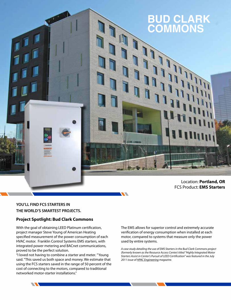
BUD CLARK COMMONS
Location: Portland, ORFCS Product: EMS Starters
Project Spotlight: Bud Clark Commons
With the goal of obtaining LEED Platinum certification, project manager Steve Young of American Heating specified measurement of the power consumption of each HVAC motor. Franklin Control Systems EMS starters, with integrated power metering and BACnet communications, proved to be the perfect solution.“I loved not having to combine a starter and meter. ” Young said. “This saved us both space and money. We estimate that using the FCS starters saved in the range of 50 percent of the cost of connecting to the motors, compared to traditional networked motor-starter installations.”
A case study detailing the use of EMS Starters in the Bud Clark Commons project (formerly known as the Resource Access Center) titled “Highly Integrated Motor Starters Assist in Center’s Pursuit of LEED Certification” was featured in the July 2011 issue of HPAC Engineering magazine.
YOU’LL FIND FCS STARTERS IN THE WORLD’S SMARTEST PROJECTS.
The EMS allows for superior control and extremely accurate verification of energy consumption when installed at each motor, compared to systems that measure only the power used by entire systems.

HOW OUR STARTER MAKES YOU SMARTER
Comprehensive Metering Pulse/Analog for complete data stream options
Proof of Flow StatusDetects belt loss, enhances comfort/saves equipment
BACnet CompatibleComprehensive energy monitoring and control
Controls CompatibilityFast installation and complete interoperability
Electronic Motor ProtectionSuperior Motor Protection & cycle protection
Fireman’s OverrideSmoke Purge Input
Wide Range OverloadPrevents call backs due to incorrect overloads
Integrated Damper ControlSave on panel points
The Energy Management Starter (EMS)

4 www.franklin-controls.com | 1.800.962.3787
Across the Line StartersEnergy Management Starter (EMS) 6Building Automation Starter (BAS) 14Standard Automation Starter (SAS) 201Ø Building Automation Starter (BAS-1P) 24
Reduced Voltage StartersEnergy Management Soft-Starter (EMS-RV) 26Standard Automation Soft Starter (SAS-RV) 31
CONTENTS
EMS
Energy Management Starter PG 6
BAS
Building Automation StarterPG 14
SAS
Standard Automation StarterPG 20
BAS 1P
Building Automation Starter Single PhasePG 24
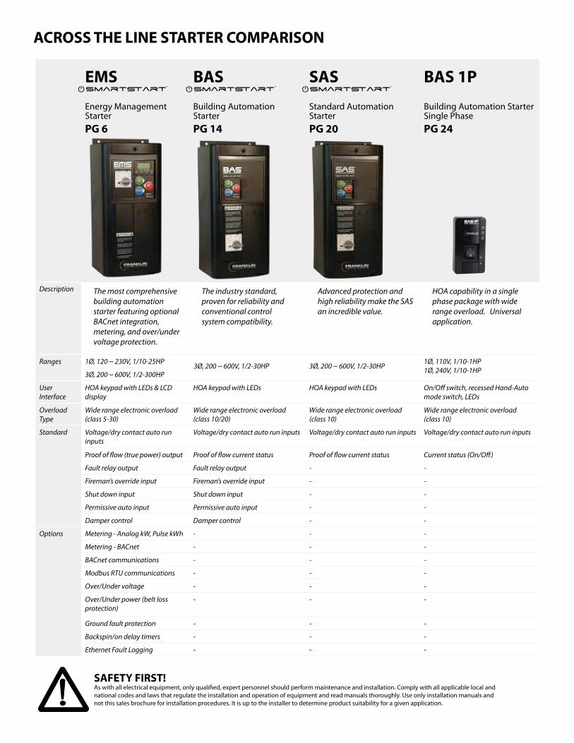
Description The most comprehensive building automation starter featuring optional BACnet integration, metering, and over/under voltage protection.
The industry standard, proven for reliability and conventional control system compatibility.
Advanced protection and high reliability make the SAS an incredible value.
HOA capability in a single phase package with wide range overload. Universal application.
Ranges 1Ø, 120 ~ 230V, 1/10-25HP3Ø, 200 ~ 600V, 1/2-30HP 3Ø, 200 ~ 600V, 1/2-30HP
1Ø, 110V, 1/10-1HP1Ø, 240V, 1/10-1HP3Ø, 200 ~ 600V, 1/2-300HP
User Interface
HOA keypad with LEDs & LCD display
HOA keypad with LEDs HOA keypad with LEDs On/Off switch, recessed Hand-Auto mode switch, LEDs
Overload Type
Wide range electronic overload (class 5-30)
Wide range electronic overload (class 10/20)
Wide range electronic overload (class 10)
Wide range electronic overload (class 10)
Standard Voltage/dry contact auto run inputs
Voltage/dry contact auto run inputs Voltage/dry contact auto run inputs Voltage/dry contact auto run inputs
Proof of flow (true power) output Proof of flow current status Proof of flow current status Current status (On/Off)
Fault relay output Fault relay output - -
Fireman’s override input Fireman’s override input - -
Shut down input Shut down input - -
Permissive auto input Permissive auto input - -
Damper control Damper control - -
Options Metering - Analog kW, Pulse kWh - - -
Metering - BACnet - - -
BACnet communications - - -
Modbus RTU communications - - -
Over/Under voltage - - -
Over/Under power (belt loss protection)
- - -
Ground fault protection - - -
Backspin/on delay timers - - -
Ethernet Fault Logging - - -
Smart�artTM
Smart�artTM
Smart�artTM
SAFETY FIRST! As with all electrical equipment, only qualified, expert personnel should perform maintenance and installation. Comply with all applicable local and national codes and laws that regulate the installation and operation of equipment and read manuals thoroughly. Use only installation manuals and not this sales brochure for installation procedures. It is up to the installer to determine product suitability for a given application.
ACROSS THE LINE STARTER COMPARISON

THE MOST INTELLIgENT STARTER YETENERgY MANAgEMENT STARTER
Power metering � 1% ANSI grade metering
� Pulse/analog output for accurate measurements (optional)
� kW and kWh data available on LCD display
Superior motor protection � Protection
- 1-95A Electronic Overload - Locked rotor - Cycle fault - Max time to start - Out of calibration (detects incorrect FLA setting)
� Selectable trip class 5-30 � Current and voltage phase unbalance � Over/under power (new standard feature!)
- Prevents free-wheeling motor damage (belt loss) � Over/under voltage
� Reverse phase
Proof of flow verification � True power measure detects belt loss and alerts automation system
� Eliminates costly current sensors
Voltage & dry contact inputs for auto run command � Wire directly from the automation system to the starter, no interposing relays necessary
� Save on installation costs and increase reliability.
Fireman’s override
� Initiates smoke purge sequence during emergency situations for safety and code compliance
Smart�artTM
1Ø, 120 ~ 230V, 1/10-25HP3Ø, 200 ~ 600V, 1/2-300HP
Smart�artTM
FEATURES
EMS
Power metering, optional BACnet or Modbus communications, and an intuitive interface allow the EMS to integrate seamlessly with building automation systems. By combining starter operation with controls, you extend equipment life and save energy. Installation is cost-effective thanks to integrated sensing and control points.
6 www.franklin-controls.com | 1.800.962.3787

7
Damper control � Provides a 24VAC (or optional 120VAC) output for powering a damper motor � Interlocks damper with starter ensuring proper sequence of operation � Prevents damage to duct work, saves energy from heat loss
� Saves on automation panel points, reduces wiring, saves on installation costs
HOA keypad with LCD display � Plain English operation – easy to set up and simple to operate
� LEDs indicate Hand/Off/Auto modes, run and fault conditions
Flexible control transformer (CPT) � Multi-tap CPT input accepts all common motor voltages
� Integrated secondary protection – no fuses required
Combination versions include disconnect � Motor circuit protection disconnect provides short circuit protection � High interrupting ratings for maximum electrical system compatibility � No fuses required – save time and money � Lockable handle for safety
BACnet or Modbus Communications with power metering for energy savings � Ideal for LEED projects (Measurement & Verification credit), tenant sub-metering
cost allocation, load shedding and performance contracting � Native RS-485 76800 BPS for high performance
Comprehensive point list including HOA status, overload faults, and all metering attributes (kW, kWh, kVar, V, A, etc. aggregate and per phase).
� Additional programmable digital input. Additional analog input, selectable between 0-10V, 4-20 mA, or 10K thermistor
� Includes power metering display with programmable parameters � Tested to BTL standards
120V Damper Control � Option in lieu of 24VAC standard
OpTIONS
Ground Fault Protection � Protects motors from damage due to ground
current conditions � UL 1053 Certified
Ethernet Fault Logging (Time & Date Stamped) � Records up to 100 faults and alarms (e.g. underpower,
overload, etc.) � Data easily is easily displayed & saved on any
web browser using an Ethernet connection. Starter incorporates internal web server. No programming required.
EMS
8 www.franklin-controls.com | 1.800.962.3787
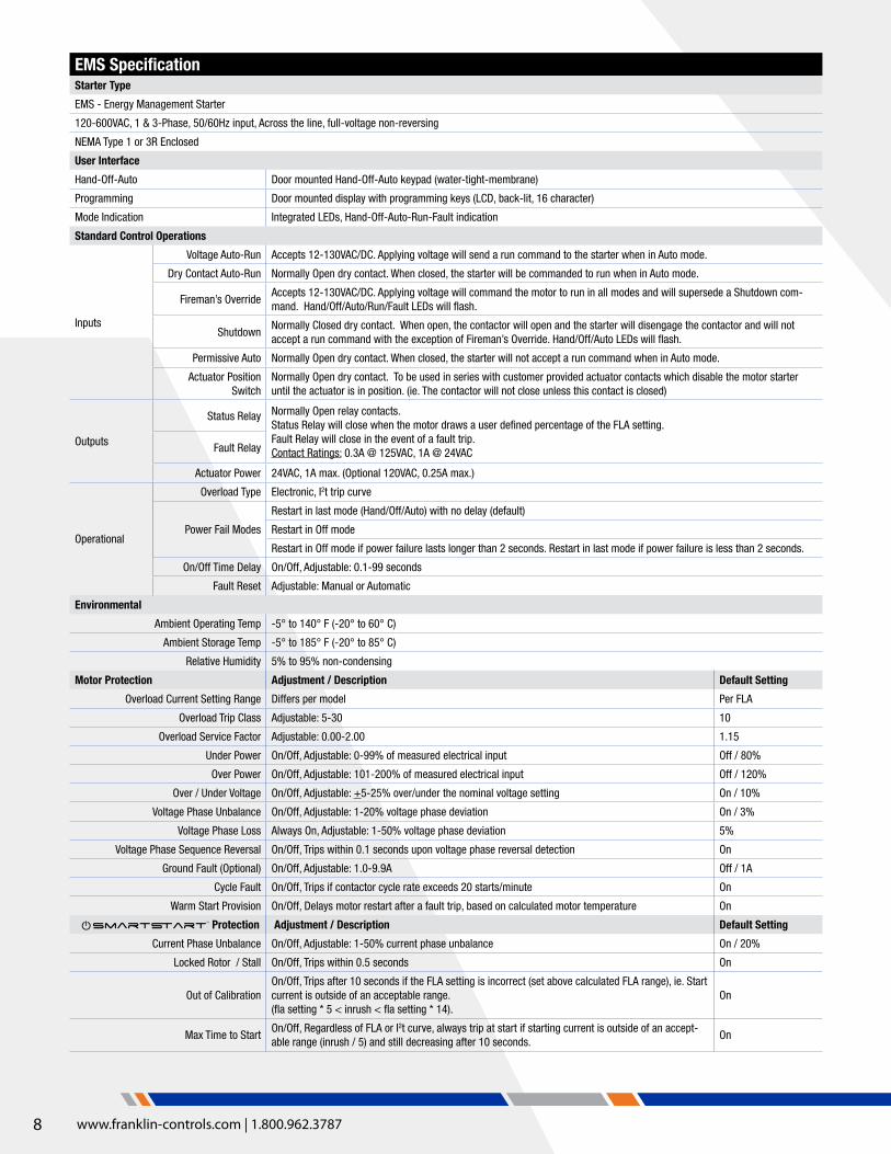
EMS SpecificationStarter Type
EMS - Energy Management Starter
120-600VAC, 1 & 3-Phase, 50/60Hz input, Across the line, full-voltage non-reversing
NEMA Type 1 or 3R Enclosed
User Interface
Hand-Off-Auto Door mounted Hand-Off-Auto keypad (water-tight-membrane)
Programming Door mounted display with programming keys (LCD, back-lit, 16 character)
Mode Indication Integrated LEDs, Hand-Off-Auto-Run-Fault indication
Standard Control Operations
Inputs
Voltage Auto-Run Accepts 12-130VAC/DC. Applying voltage will send a run command to the starter when in Auto mode.
Dry Contact Auto-Run Normally Open dry contact. When closed, the starter will be commanded to run when in Auto mode.
Fireman’s OverrideAccepts 12-130VAC/DC. Applying voltage will command the motor to run in all modes and will supersede a Shutdown com-mand. Hand/Off/Auto/Run/Fault LEDs will flash.
ShutdownNormally Closed dry contact. When open, the contactor will open and the starter will disengage the contactor and will not accept a run command with the exception of Fireman’s Override. Hand/Off/Auto LEDs will flash.
Permissive Auto Normally Open dry contact. When closed, the starter will not accept a run command when in Auto mode.
Actuator Position Switch
Normally Open dry contact. To be used in series with customer provided actuator contacts which disable the motor starter until the actuator is in position. (ie. The contactor will not close unless this contact is closed)
Outputs
Status Relay Normally Open relay contacts. Status Relay will close when the motor draws a user defined percentage of the FLA setting.Fault Relay will close in the event of a fault trip.Contact Ratings: 0.3A @ 125VAC, 1A @ 24VACFault Relay
Actuator Power 24VAC, 1A max. (Optional 120VAC, 0.25A max.)
Operational
Overload Type Electronic, I2t trip curve
Power Fail Modes
Restart in last mode (Hand/Off/Auto) with no delay (default)
Restart in Off mode
Restart in Off mode if power failure lasts longer than 2 seconds. Restart in last mode if power failure is less than 2 seconds.
On/Off Time Delay On/Off, Adjustable: 0.1-99 seconds
Fault Reset Adjustable: Manual or Automatic
Environmental
Ambient Operating Temp -5° to 140° F (-20° to 60° C)
Ambient Storage Temp -5° to 185° F (-20° to 85° C)
Relative Humidity 5% to 95% non-condensing
Motor Protection Adjustment / Description Default Setting
Overload Current Setting Range Differs per model Per FLA
Overload Trip Class Adjustable: 5-30 10
Overload Service Factor Adjustable: 0.00-2.00 1.15
Under Power On/Off, Adjustable: 0-99% of measured electrical input Off / 80%
Over Power On/Off, Adjustable: 101-200% of measured electrical input Off / 120%
Over / Under Voltage On/Off, Adjustable: +5-25% over/under the nominal voltage setting On / 10%
Voltage Phase Unbalance On/Off, Adjustable: 1-20% voltage phase deviation On / 3%
Voltage Phase Loss Always On, Adjustable: 1-50% voltage phase deviation 5%
Voltage Phase Sequence Reversal On/Off, Trips within 0.1 seconds upon voltage phase reversal detection On
Ground Fault (Optional) On/Off, Adjustable: 1.0-9.9A Off / 1A
Cycle Fault On/Off, Trips if contactor cycle rate exceeds 20 starts/minute On
Warm Start Provision On/Off, Delays motor restart after a fault trip, based on calculated motor temperature On
Protection Adjustment / Description Default Setting
Current Phase Unbalance On/Off, Adjustable: 1-50% current phase unbalance On / 20%
Locked Rotor / Stall On/Off, Trips within 0.5 seconds On
Out of CalibrationOn/Off, Trips after 10 seconds if the FLA setting is incorrect (set above calculated FLA range), ie. Start current is outside of an acceptable range. (fla setting * 5 < inrush < fla setting * 14).
On
Max Time to StartOn/Off, Regardless of FLA or I2t curve, always trip at start if starting current is outside of an accept-able range (inrush / 5) and still decreasing after 10 seconds.
On
Smart�artTM

9
Control wiring Power wiring
EMS WIRINg DIAgRAM
EMS
JDS*
24VAC, 1A Output
DMN.O. Input
H1 H4H1 H4
L1 L2
T1 T3
M
MCP
L3
T2
A B C
CAT 5
1PH 3PH
OL
43/13
44/14
31/21
32/22
L1
T1 T3
M
MCP
L2
A B C
CAT 5Output Output
OL
M
SCHM-EMS/C/50VA-V1
NOTES:1. DASHED LINES INDICATE FIELD WIRING2. REMOVE JUMPER JDS TO WIRE LIMIT SWITCH3. REMOVE JUMPER JSD TO WIRE SHUTDOWN INPUT4. X1 AND X2 TERMINALS APPLY FOR TYPE 3R ENCLOSED STARTERS ONLY
A1
A2M
24V
240V 480V208V
50VACPT
SCM PCB
ActuatorControl
VoltageInputs
RelayOutputs
DryInputs
CommonShutdown(Perm Auto)Auto Run(Perm Auto)
Common
Fault
Status
Fireman’sOverride
Auto Run
Normally Open Input
Normally Closed Input
12-120VAC/DC Input
12-120VAC/DC Input
120V
CAT 5 Input
Common
Motor
Limit Switch
H1 H4
X1 X2*Note 4
575V
A
A1
A2
V1
V2
V3
V4
O1
O2
O
D1
D
D2
L1 L2 L3
T1 T2 T3
GND GND
JSD*
43/13
44/14
31/21
32/22
M
L1 L2 L3
T1 T2 T3

10 www.franklin-controls.com | 1.800.962.3787
Energy Management Starter - 1 & 3-Phase, 50/60 Hz, 120~575 VAC
UL Type 1 Enclosed - Combination Starter, SCM Electronic Overload
Includes MCP Disconnect
Part Number
UL HP RatingsSCIC KAIC @ Contactor
NEMA Size1Ø 3Ø
120V 230V 208V 230V 460V 575V 240V 460V
EMS1-9/J-G1.6-9 - 1/10 - - 3/4 3/4 100 65
00
EMS1-9/J-G2.5-9 - 1/6 1/2 1/2 1 1.5 100 65
EMS1-9/J-G4-9 1/8 1/3 3/4 3/4 2 3 100 65
EMS1-9/J-G6-9 1/4 1/2 1 1.5 3 5 100 65
EMS1-9/J-G8-9 1/3 1 2 2 5 5 100 65
EMS1-18/J-G10-18 1/2 1.5 2 3 5 7.5 100 65
0EMS1-18/J-G13-18 1/2 2 3 3 7.5 10 100 65
EMS1-18/J-G17-18 1 3 3 5 10 15 100 30
EMS1-32/J-G22-32 1.5 3 5 7.5 15 20 100 30
1EMS1-32/J-G26-32 2 3 7.5 7.5 15 20 100 30
EMS1-32/J-G32-32 2 5 7.5 10 20 30 100 30
EMS1-50/J-G40-50 3 7.5 10 10 30 30 100 502
EMS1-50/J-G50-50 3 10 15 15 30 40 100 50
EMS1-85/J-G63-85 5 10 20 20 40 - 100 50
3EMS1-85/J-G75-85 5 15 20 25 50 - 100 50
EMS1-85/J-G90-85 7.5 20 25 30 60 - 100 50
Ordering and Sizing Information (120~575 VAC)UL Type 3R Enclosed
Energy Management Starter - 1 & 3-Phase, 50/60 Hz, 120~575 VAC
UL Type 1 Enclosed - Standard Starter, SCM Electronic Overload
Disconnect Not Included
Part Number
UL HP RatingsSCIC KAIC @ Contactor
NEMA Size1Ø 3Ø
120V 230V 208V 230V 460V 575V 240V 460V
EMS1-9/J-9 1/3 1 2 2 5 7.5 5 5 00
EMS1-18/J-18 1 3 5 5 10 15 5 5 0
EMS1-32/J-32 2 5 7.5 10 20 25 5 5 1
EMS1-50/J-50 3 10 15 15 30 40 5 5 2
EMS1-85/J-85 7.5 15 25 30 60 - 10 10 3
NEMA 1 Factory Installable OptionsPart Number Description
EMS-BN-COM/* BACnet communications card with power metering
EMS-MB-COM* Modbus RTU communications card
EMS-PWR* Power metering card with pulse/analog output
EMS-ENET* Ethernet data and fault logging card
EMS-GFLT Ground fault protection (UL1053 certified)
EMS-120 120VAC control circuit and damper/actuator control (in lieu of 24VAC)
EMS-1PH 1-phase wiring for EMS starters
*Items cannot be installed in combination with other items marked with “*”
Stan
dard
Com
bina
tion
Consult factory for type 4 & 4X enclosed EMS starters
*For NEMA Size 3, 575V applications, please consult factory
*For NEMA Size 3, 575V applications, please consult factory

11
Stan
dard
Com
bina
tion
Consult factory for type 4 & 4X enclosed EMS starters
Energy Management Starter - 1 & 3-Phase, 50/60 Hz, 120~575 VAC
UL Type 3R Enclosed - Combination Starter, SCM Electronic Overload
Includes MCP Disconnect
Part Number
UL HP RatingsSCIC KAIC @ Contactor
NEMA Size1Ø 3Ø
120V 230V 208V 230V 460V 575V 240V 460V
EMS3R-9/J-G1.6-9 - 1/10 - - 3/4 3/4 100 65
00
EMS3R-9/J-G2.5-9 - 1/6 1/2 1/2 1 1.5 100 65
EMS3R-9/J-G4-9 1/8 1/3 3/4 3/4 2 3 100 65
EMS3R-9/J-G6-9 1/4 1/2 1 1.5 3 5 100 65
EMS3R-9/J-G8-9 1/3 1 2 2 5 5 100 65
EMS3R-18/J-G10-18 1/2 1.5 2 3 5 7.5 100 65
0EMS3R-18/J-G13-18 1/2 2 3 3 7.5 10 100 65
EMS3R-18/J-G17-18 1 3 3 5 10 15 100 30
EMS3R-32/J-G22-32 1.5 3 5 7.5 15 20 100 30
1EMS3R-32/J-G26-32 2 3 7.5 7.5 15 20 100 30
EMS3R-32/J-G32-32 2 5 7.5 10 20 30 100 30
EMS3R-50/J-G40-50 3 7.5 10 10 30 30 100 502
EMS3R-50/J-G50-50 3 10 15 15 30 40 100 50
EMS3R-85/J-G63-85 5 10 20 20 40 - 100 50
3EMS3R-85/J-G75-85 5 15 20 25 50 - 100 50
EMS3R-85/J-G90-85 7.5 20 25 30 60 - 100 50
Energy Management Starter - 1 & 3-Phase, 50/60 Hz, 120~575 VAC
UL Type 3R Enclosed - Standard Starter, SCM Electronic Overload
Disconnect Not Included
Part Number
UL HP RatingsSCIC KAIC @ Contactor
NEMA Size1Ø 3Ø
120V 230V 208V 230V 460V 575V 240V 460V
EMS1-9/J-9 1/3 1 2 2 5 7.5 5 5 00
EMS1-18/J-18 1 3 5 5 10 15 5 5 0
EMS1-32/J-32 2 5 7.5 10 20 25 5 5 1
EMS1-50/J-50 3 10 15 15 30 40 5 5 2
EMS1-85/J-85 7.5 15 25 30 60 - 10 10 3
NEMA 3R Factory Installable OptionsPart Number Description
EMS-BN-COM/3R* BACnet communications card with power metering
EMS-MB-COM/3R* Modbus RTU communications card
EMS-PWR/3R* Power metering card with pulse/analog output
EMS-ENET/3R* Ethernet data and fault logging card
EMS-GFLT Ground fault protection (UL1053 certified)
EMS-120 120VAC control circuit and damper/actuator control (in lieu of 24VAC)
EMS-1PH 1-phase wiring for EMS starters
*Items cannot be installed in combination with other items marked with “*”
Ordering and Sizing Information (120~575 VAC)UL Type 3R Enclosed
EMS
*For NEMA Size 3, 575V applications, please consult factory
*For NEMA Size 3, 575V applications, please consult factory
12 www.franklin-controls.com | 1.800.962.3787
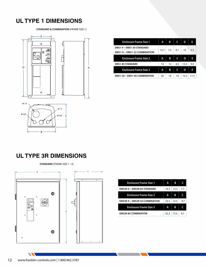
Enclosure Frame Size 2 A B C D E
EMS1-85 STANDARD 14 12 6.5 13.3 9.5
Enclosure Frame Size 3 A B C D E
EMS1-50 ~ EMS1-85 COMBINATION 20 16 10 15.3 11.3
Enclosure Frame Size 1 A B C D E
EMS1-9 ~ EMS1-50 STANDARD15.7 7.5 6.1 15 5.3
EMS1-9 ~ EMS1-32 COMBINATION
AD
E
B
C
Ø 1.73
Ø 0.86Ø 0.86
Ø 1.12
Enclosure Frame Size 1 A B C
EMS3R-9 ~ EMS3R-85 STANDARD 16.3 12.5 7.7
Enclosure Frame Size 2 A B C
EMS3R-9 ~ EMS3R-50 COMBINATION 22.3 15.5 9.7
Enclosure Frame Size 3 A B C
EMS3R-85 COMBINATION 32.3 15.5 9.7
STANDARD (FRAME SIZE 1 - 3)
STANDARD & COMBINATION (FRAME SIZE 1)
UL TYpE 1 DIMENSIONS
UL TYpE 3R DIMENSIONS

13
Project Spotlight: 2nd Brigade Barracks Location: Fort Bragg, NC
The Army Corps of Engineers utilized Franklin Control Systems BAS starters in the construction of the new 2nd Brigade Barracks. FCS supplied over 80 BAS units to control air handling units, return fans and chilled water pumps across five separate buildings within the complex.
The BAS includes a standard wide-range electronic overload which eliminated the need to individually size “heaters” resulting in both labor savings and the reduction of man-hours required to select equipment. Since BAS units always ship tagged for scheduled equipment, the installers easily matched starters to the correct location, which resulted in a much faster installation.
FORT BRAGG
YOU’LL FIND FCS STARTERS IN THE WORLD’S SMARTEST PROJECTS.

14 www.franklin-controls.com | 1.800.962.3787
BAS
SMARTER AND MORE VERSATILE THAN EVERBUILDINg AUTOMATION STARTER Equipped with advanced I/O including Fireman’s Override and damper control, the BAS was designed from the ground up for easy integration with automation systems. With a 200 to 600V input and 1-40A adjustable overload, the BAS is the right starter for almost any job.
Designed for ease of integration with automation systems
� Comprehensive inputs/outputs for building automation systems
� Reduces installation costs
� High reliability
patented superior motor protection
� Electronic overload protection including locked rotor, cycle fault and maximum time to start (due to mis-sized motor or overload)
� FLA out of calibration indication--ensures installer sets overload correctly based on calculated motor size
Advanced control inputs eliminate interposing relays
� Three dry inputs for auto-run, permissive auto and shutdown
� Two voltage inputs (12-250VAC) for auto run and fireman’s override
Logging retains critical information � Logging information is obtainable for starter
failure (Factory retrievable only) � Last 10 start conditions, including FLA
setting, max inrush, run current, time to start, and safety start mode.
� Last 10 fault conditions, including FLA setting, fault type, fault current, and run time.
Universal application � Automatically detects voltage
(200 to 600VAC) � Converts to 24V for control power
UL Type 1 and 3R enclosures � Lockable enclosure � 3R features lockable keypad cover � Type 4 & 4X enclosure options available
(consult factory)
Hand/Off/Auto keypad with LED status indicators
� Intuitive operation and control with Hand (manual run), Off, and Auto run modes
Combination versions include disconnect
� Motor circuit protection disconnect provides short circuit protection
� High interrupting ratings for maximum electrical system compatibility
� No fuses required � Lockable handle for safety
Smart�artTM
3Ø, 200 ~ 600V, 1/2-30HP
Smart�artTM
FEATURES

15
Building Management System (BMS)
Fireman’s Override Emergency
Shut-down
Auxiliary Input - Run
Command
Motor Fan Damper
Auxiliary Input - Stop
Command
Fault Alarm
Damper Control Output
Limit Switch Closed Signal
Motor Status
Signal in
Signal outBAS Only
Signal in
Signal outBAS & SAS
THE BAS IS AUTOMATION READY.
Image provided by Greenheck Fan Corporation
Smart - Start safely even without calibration! patented technology predicts a safe operating range for your motor based on the measured inrush current
Intelligent - detects if your starter needs to be calibrated, protecting you from operators trying to overcome motor jams or problems by over-setting the overload. With Smartstart enabled, if the starter isn’t in range, it alarms and trips notifying you before damage occurs
Active - detects harmful extended starting conditions with maximum time to start. Monitors motor inrush current conditions and trips if the motor doesn’t start within 10 seconds (class 10 overload) regardless of FLA setting.
Ingenious - Active current monitoring provides superior protection against locked rotor and stall conditions, tripping faster than a standard inverse trip curve, regardless of the FLA setting!
Thoughtful - “Blackbox” recording feature retains critical information on last ten faults and starts (factory retrievable only).
1 2 3 4 5 6 7 8 9 10
FLA
Current (amps)
FLA6-10x
Motor Inrush
Start Time (seconds)
Standard Start Curve
Locked Rotor Trip
Stall Trip (Disabled during startup)
Max Time to Start Trip
Standard Motor Starting Current
Motor Never Reaches FLA
Typical Motor Stall Current
Locked Rotor CurrentSmart�art
TM
Smart�artTM
Smart�artTM
Smart�artTM
The Technology behind
Smart�artTM
BAS
16 www.franklin-controls.com | 1.800.962.3787
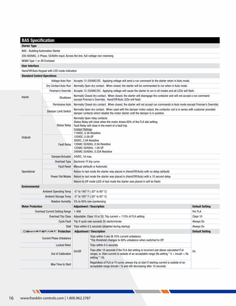
BAS SpecificationStarter Type
BAS - Building Automation Starter
200-600VAC, 3-Phase, 50/60Hz input, Across the line, full-voltage non-reversing
NEMA Type 1 or 3R Enclosed
User Interface
Hand/Off/Auto Keypad with LED mode indication
Standard Control Operations
Inputs
Voltage Auto-Run Accepts 12-250VAC/DC. Applying voltage will send a run command to the starter when in Auto mode.
Dry Contact Auto-Run Normally Open dry contact. When closed, the starter will be commanded to run when in Auto mode.
Fireman’s Override Accepts 12-250VAC/DC. Applying voltage will cause the starter to run in all modes and all LEDs will flash.
ShutdownNormally Closed dry contact. When closed, the starter will disengage the contactor and will not accept a run command (except Fireman’s Override). Hand/Off/Auto LEDs will flash.
Permissive Auto Normally Closed dry contact. When closed, the starter will not accept run commands in Auto mode (except Fireman’s Override)
Damper Limit SwitchNormally Open dry contact. When used with the damper motor output, the contactor coil is in series with customer provided damper contacts which disable the motor starter until the damper is in position.
Outputs
Status Relay
Normally Open relay contacts. Status Relay will close when the motor draws 60% of the FLA dial setting.Fault Relay will close in the event of a fault trip.Contact Ratings:110VDC, 0.3A Resistive125VDC, 0.5A GP30VDC, 2.0A Resistive120VAC 50/60Hz, 0.5A Resistive125VAC 50/60Hz, 1.0A GP240VAC 50/60Hz, 0.25A Resistive
Fault Relay
Damper/Actuator 24VDC, 1A max.
Operational
Overload Type Electronic I2t trip curve
Fault Reset Manual (default) or Automatic
Power Fail Modes
Return to last mode the starter was placed in (Hand/Off/Auto) with no delay (default)
Return to last mode the starter was placed in (Hand/Off/Auto) with a 10 second delay
Return to Off mode (LED of last mode the starter was placed in will be flash)
Environmental
Ambient Operating Temp -5° to 140° F (-20° to 60° C)
Ambient Storage Temp -5° to 185° F (-20° to 85° C)
Relative Humidity 5% to 95% non-condensing
Motor Protection Adjustment / Description Default Setting
Overload Current Setting Range 1-40A Per FLA
Overload Trip Class Adjustable: Class 10 or 20, Trip current = 115% of FLA setting Class 10
Cycle Fault Trip if cycle rate exceeds 20 starts/minute Always On
Stall Trips within 0.5 seconds (disabled during startup) Always On
Protection Adjustment / Description Default Setting
Current Phase Unbalance
On/Off
Trips within 3 sec @ 25% current unbalance. *Trip threshold changes to 80% unbalance when switched to Off
On
Locked Rotor Trips within 0.5 seconds
Out of CalibrationTrips after 10 seconds if the FLA dial setting is incorrect (set above calculated FLA range), ie. Start current is outside of an acceptable range (fla setting * 5 < inrush < fla setting * 14).
Max Time to StartRegardless of FLA or I2t curve, always trip at start if starting current is outside of an acceptable range (inrush / 5) and still decreasing after 10 seconds.
Smart�artTM
17
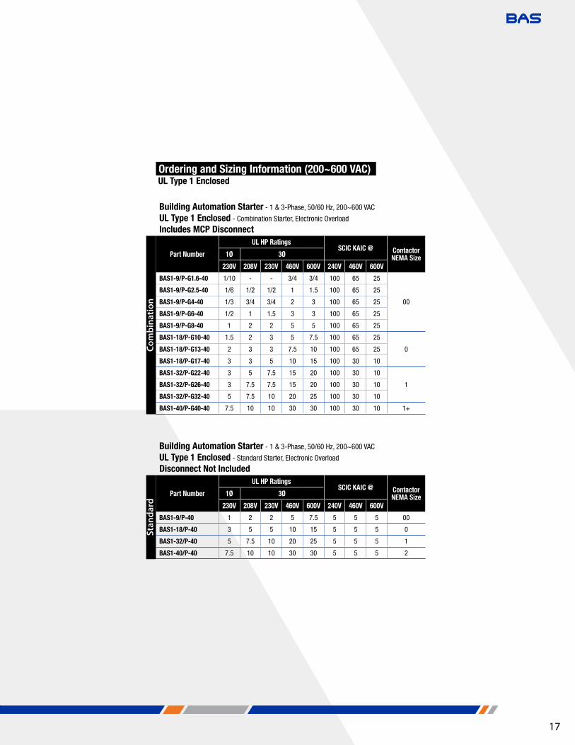
Building Automation Starter - 1 & 3-Phase, 50/60 Hz, 200~600 VAC
UL Type 1 Enclosed - Combination Starter, Electronic Overload
Includes MCP Disconnect
Part Number
UL HP RatingsSCIC KAIC @ Contactor
NEMA Size1Ø 3Ø
230V 208V 230V 460V 600V 240V 460V 600V
BAS1-9/P-G1.6-40 1/10 - - 3/4 3/4 100 65 25
00
BAS1-9/P-G2.5-40 1/6 1/2 1/2 1 1.5 100 65 25
BAS1-9/P-G4-40 1/3 3/4 3/4 2 3 100 65 25
BAS1-9/P-G6-40 1/2 1 1.5 3 3 100 65 25
BAS1-9/P-G8-40 1 2 2 5 5 100 65 25
BAS1-18/P-G10-40 1.5 2 3 5 7.5 100 65 25
0BAS1-18/P-G13-40 2 3 3 7.5 10 100 65 25
BAS1-18/P-G17-40 3 3 5 10 15 100 30 10
BAS1-32/P-G22-40 3 5 7.5 15 20 100 30 10
1BAS1-32/P-G26-40 3 7.5 7.5 15 20 100 30 10
BAS1-32/P-G32-40 5 7.5 10 20 25 100 30 10
BAS1-40/P-G40-40 7.5 10 10 30 30 100 30 10 1+
Ordering and Sizing Information (200~600 VAC) UL Type 1 Enclosed
Building Automation Starter - 1 & 3-Phase, 50/60 Hz, 200~600 VAC
UL Type 1 Enclosed - Standard Starter, Electronic Overload
Disconnect Not Included
Part Number
UL HP RatingsSCIC KAIC @ Contactor
NEMA Size1Ø 3Ø
230V 208V 230V 460V 600V 240V 460V 600V
BAS1-9/P-40 1 2 2 5 7.5 5 5 5 00
BAS1-18/P-40 3 5 5 10 15 5 5 5 0
BAS1-32/P-40 5 7.5 10 20 25 5 5 5 1
BAS1-40/P-40 7.5 10 10 30 30 5 5 5 2
Com
bina
tion
Stan
dard
BAS

18 www.franklin-controls.com | 1.800.962.3787
*NEMA 4X & 12 enclosures available upon request
The new BAS 3R enclosure is significantly smaller and lighter than its predecessor
Building Automation Starter - 1 & 3-Phase, 50/60 Hz, 200~600 VAC
UL Type 3R Enclosed - Combination Starter, Electronic Overload
Includes MCP Disconnect
Part Number
UL HP RatingsSCIC KAIC @ Contactor
NEMA Size1Ø 3Ø
230V 208V 230V 460V 600V 240V 460V 600V
BAS3R-9/P-G1.6-40 1/10 - - 3/4 3/4 100 65 25
00
BAS3R-9/P-G2.5-40 1/6 1/2 1/2 1 1.5 100 65 25
BAS3R-9/P-G4-40 1/3 3/4 3/4 2 3 100 65 25
BAS3R-9/P-G6-40 1/2 1 1.5 3 3 100 65 25
BAS3R-9/P-G8-40 1 2 2 5 5 100 65 25
BAS3R-18/P-G10-40 1.5 2 3 5 7.5 100 65 25
0BAS3R-18/P-G13-40 2 3 3 7.5 10 100 65 25
BAS3R-18/P-G17-40 3 3 5 10 15 100 30 10
BAS3R-32/P-G22-40 3 5 7.5 15 20 100 30 10
1BAS3R-32/P-G26-40 3 7.5 7.5 15 20 100 30 10
BAS3R-32/P-G32-40 5 7.5 10 20 25 100 30 10
BAS3R-40/P-G40-40 7.5 10 10 30 30 100 30 10 1+
Building Automation Starter - 1 & 3-Phase, 50/60 Hz, 200~600 VAC
UL Type 3R Enclosed - Standard Starter, Electronic Overload
Disconnect Not Included
Part Number
UL HP RatingsSCIC KAIC @ Contactor
NEMA Size1Ø 3Ø
230V 208V 230V 460V 600V 240V 460V 600V
BAS3R-9/P-40 1 2 2 5 7.5 5 5 5 00
BAS3R-18/P-40 3 5 5 10 15 5 5 5 0
BAS3R-32/P-40 5 7.5 10 20 25 5 5 5 1
BAS3R-40/P-40 7.5 10 10 30 30 5 5 5 2
Ordering and Sizing Information (200~600 VAC) UL Type 3R Enclosed
Com
bina
tion
Stan
dard

19
All dimensions are in inches
All dimensions are in inches
H1 H4
L3L1 L2MTR
T1 T3 AUXCONT
M
T2
OL
3PH
43
44
31
32
BAS STARTERPOWER WIRING
A1
A2M
BAS CONTROL WIRING
Motor
Limit Switch Normally Open Input
ActuatorControl
24VDC, 1A Output
DryInputs
RelayOutputs Common
Fault
Status
Fireman’sOverride 12-250VAC/DC Input
Auto Run
Permissive
Shut Down
Auto Run 12-250VAC/DC InputVoltageInputs
ContactorCoil
1
FLA (A)
5
1015 20
25
30
35
40
PCB Power
H1 H4
Keypad
Overload Setting
Normally Open Input
Normally Open Input
Normally Closed Input
MCP(Optional)
24V Output to contactor coil
208-600 VACInput
L1 L2 L3
T1 T3 T3
L1 L2 L3
T1 T2 T3
H1 H4
L3L1 L2MTR
T1 T3 AUXCONT
M
T2
OL
3PH
43
44
31
32
BAS STARTERPOWER WIRING
A1
A2M
BAS CONTROL WIRING
Motor
Limit Switch Normally Open Input
ActuatorControl
24VDC, 1A Output
DryInputs
RelayOutputs Common
Fault
Status
Fireman’sOverride 12-250VAC/DC Input
Auto Run
Permissive
Shut Down
Auto Run 12-250VAC/DC InputVoltageInputs
ContactorCoil
1
FLA (A)
5
1015 20
25
30
35
40
PCB Power
H1 H4
Keypad
Overload Setting
Normally Open Input
Normally Open Input
Normally Closed Input
MCP(Optional)
24V Output to contactor coil
208-600 VACInput
L1 L2 L3
T1 T3 T3
L1 L2 L3
T1 T2 T3
*NEMA 4X & 12 enclosures available upon request
BAS WIRINg DIAgRAM
UL TYpE 1 DIMENSIONS
UL TYpE 3R DIMENSIONS
BAS

20 www.franklin-controls.com | 1.800.962.3787
ADVANCED pROTECTION, INCREDIBLE VALUESTANDARD AUTOMATION STARTER Like the BAS, the SAS accepts 200 to 600VAC incoming power, making it a plug and play device. The 1-40A electronic overload ensures you will have the right starter for the job, and Smartstart revolutionary technology protects motors from potentially harmful start-up conditions. The SAS is automation compatible.
Control inputs eliminate interposing relays
� Wet & dry auto run inputs
UL Type 1 and 3R enclosures � Lockable enclosure
� 3R features lockable keypad cover
Hand/Off/Auto keypad with LED status indicators
� Intuitive operation and control with Hand (manual run), Off, and Auto run modes
Logging retains critical information � Logging information is obtainable for starter
failure (Factory retrievable only) � Last 10 start conditions, including FLA
setting, max inrush, run current, time to start, and safety start mode.
� Last 10 fault conditions, including FLA setting, fault type, fault current, and run time.
Smart�artTM
Automation compatible
� Higher reliability � Comprehensive inputs/outputs for energy
management systems � Reduces installation costs
� Increased energy savings
patented superior motor protection
� Electronic overload protection including locked rotor, cycle fault and maximum time to start (due to mis-sized motor or overload)
� FLA out of calibration indication-- ensures installer sets overload correctly based on calculated motor size
Wide range overload, universal application
� 1-40A electronic overload eliminates call backs due to mis-sized heaters
� Accepts 200 to 600VAC
Combination versions include disconnect
� Motor circuit protection disconnect provides short circuit protection
� High interrupting ratings for maximum electrical system compatibility
� No fuses required � Lockable handle for safety
3Ø, 200 ~ 600V, 1/2-30HP
Smart�artTM
FEATURES
SAS

21
SAS SpecificationStarter Type
SAS - Standard Automation Starter
200-600VAC, 3-Phase, 50/60Hz input, Across the line, full-voltage non-reversing
NEMA Type 1 or 3R Enclosed
User Interface
Hand/Off/Auto Keypad with LED mode indication
Standard Control Operations
InputsVoltage Auto-Run Accepts 12-250VAC/DC. Applying voltage will send a run command to the starter when in Auto mode.
Dry Contact Auto-Run Normally Open dry contact. When closed, the starter will be commanded to run when in Auto mode.
Output Status Relay
Normally Open relay contact. Status Relay will close when the motor draws 60% of the FLA dial setting.Contact Ratings:110VDC, 0.3A Resistive125VDC, 0.5A GP30VDC, 2.0A Resistive120VAC 50/60Hz, 0.5A Resistive125VAC 50/60Hz, 1.0A GP240VAC 50/60Hz, 0.25A Resistive
Operational
Overload Type Electronic I2t trip curve
Fault Reset Manual (default) or Automatic
Power Fail Mode Return to last mode the starter was placed in (Hand/Off/Auto) with no delay (default)
Environmental
Ambient Operating Temp -5° to 140° F (-20° to 60° C)
Ambient Storage Temp -5° to 185° F (-20° to 85° C)
Relative Humidity 5% to 95% non-condensing
Motor Protection Adjustment / Description Default Setting
Overload Current Setting Range 1-40A Per FLA
Overload Trip Class Class 10, Trip current = 115% of FLA setting Class 10
Cycle Fault Trip if cycle rate exceeds 20 starts/minute Always On
Stall Trips within 0.5 seconds (disabled during startup) Always On
Protection Adjustment / Description Default Setting
Current Phase Unbalance
On/Off
Trips within 3 sec @ 25% current unbalance. *Trip threshold changes to 80% unbalance when switched to Off
On
Locked Rotor Trips within 0.5 seconds
Out of CalibrationTrips after 10 seconds if the FLA dial setting is incorrect (set above calculated FLA range), ie. Start current is outside of an acceptable range (fla setting * 5 < inrush < fla setting * 14).
Max Time to StartRegardless of FLA or I2t curve, always trip at start if starting current is outside of an acceptable range (inrush / 5) and still decreasing after 10 seconds.
SAS
Smart�artTM

22 www.franklin-controls.com | 1.800.962.3787
Building Automation Starter - 1 & 3-Phase, 50/60 Hz, 200~600 VAC
UL Type 1 Enclosed - Combination Starter, Electronic Overload
Includes MCP Disconnect
Part Number
UL HP RatingsSCIC KAIC @ Contactor
NEMA Size
1Ø 3Ø
230V 208V 230V 460V 600V 240V 460V 600V
SAS1-9/P-G1.6-40 1/10 - - 3/4 3/4 100 65 25
00
SAS1-9/P-G2.5-40 1/6 1/2 1/2 1 1.5 100 65 25
SAS1-9/P-G4-40 1/3 3/4 3/4 2 3 100 65 25
SAS1-9/P-G6-40 1/2 1 1.5 3 3 100 65 25
SAS1-9/P-G8-40 1 2 2 5 5 100 65 25
SAS1-18/P-G10-40 1.5 2 3 5 7.5 100 65 25
0SAS1-18/P-G13-40 2 3 3 7.5 10 100 65 25
SAS1-18/P-G17-40 3 3 5 10 15 100 30 10
SAS1-32/P-G22-40 3 5 7.5 15 20 100 30 10
1SAS1-32/P-G26-40 3 7.5 7.5 15 20 100 30 10
SAS1-32/P-G32-40 5 7.5 10 20 25 100 30 10
SAS1-40/P-G40-40 7.5 10 10 30 30 100 30 10 1+
Ordering and Sizing Information (200~600 VAC) UL Type 1 Enclosed
Building Automation Starter - 1 & 3-Phase, 50/60 Hz, 200~600 VAC
UL Type 1 Enclosed - Standard Starter, Electronic Overload
Disconnect Not Included
Part Number
UL HP RatingsSCIC KAIC @ Contactor
NEMA Size
1Ø 3Ø
230V 208V 230V 460V 600V 240V 460V 600V
SAS1-9/P-40 1 2 2 5 7.5 5 5 5 00
SAS1-18/P-40 3 5 5 10 15 5 5 5 0
SAS1-32/P-40 5 7.5 10 20 25 5 5 5 1
SAS1-40/P-40 7.5 10 10 30 30 5 5 5 2
Building Automation Starter - 1 & 3-Phase, 50/60 Hz, 200~600 VAC
UL Type 3R Enclosed - Combination Starter, Electronic Overload
Includes MCP Disconnect
Part Number
UL HP RatingsSCIC KAIC @ Contactor
NEMA Size
1Ø 3Ø
230V 208V 230V 460V 600V 240V 460V 600V
SAS3R-9/P-G1.6-40 1/10 - - 3/4 3/4 100 65 25
00
SAS3R-9/P-G2.5-40 1/6 1/2 1/2 1 1.5 100 65 25
SAS3R-9/P-G4-40 1/3 3/4 3/4 2 3 100 65 25
SAS3R-9/P-G6-40 1/2 1 1.5 3 3 100 65 25
SAS3R-9/P-G8-40 1 2 2 5 5 100 65 25
SAS3R-18/P-G10-40 1.5 2 3 5 7.5 100 65 25
0SAS3R-18/P-G13-40 2 3 3 7.5 10 100 65 25
SAS3R-18/P-G17-40 3 3 5 10 15 100 30 10
SAS3R-32/P-G22-40 3 5 7.5 15 20 100 30 10
1SAS3R-32/P-G26-40 3 7.5 7.5 15 20 100 30 10
SAS3R-32/P-G32-40 5 7.5 10 20 25 100 30 10
SAS3R-40/P-G40-40 7.5 10 10 30 30 100 30 10 1+
Building Automation Starter - 1 & 3-Phase, 50/60 Hz, 200~600 VAC
UL Type 3R Enclosed - Standard Starter, Electronic Overload
Disconnect Not Included
Part Number
UL HP RatingsSCIC KAIC @ Contactor
NEMA Size
1Ø 3Ø
230V 208V 230V 460V 600V 240V 460V 600V
SAS3R-9/P-40 1 2 2 5 7.5 5 5 5 00
SAS3R-18/P-40 3 5 5 10 15 5 5 5 0
SAS3R-32/P-40 5 7.5 10 20 25 5 5 5 1
SAS3R-40/P-40 7.5 10 10 30 30 5 5 5 2
Ordering and Sizing Information (200~600 VAC)UL Type 3R Enclosed
The new SAS 3R enclosure is significantly smaller and lighter than its predecessor
*For larger HP SAS starters, please consult factory (larger HP models not available with Smartstart™)

23
All dimensions are in inches
All dimensions are in inches
H1 H4
L3L1 L2MTR
T1 T3 AUXCONT
M
T2
OL
3PH
43
44
31
32
SAS STARTERPOWER WIRING
A1
A2M
SAS CONTROL WIRING
DryInput
Relay Output Status
Auto Run
VoltageInput
ContactorCoil
1
FLA (A)
5
1015 20
25
30
35
40
PCB Power
H1 H4
Auto Run 12-250VAC/DC Input
Keypad
Overload Setting
Normally Open Input
MCP(Optional)
SCHM-SAS-V3
24V Output to contactor coil
208-600 VACInput
L1 L2 L3
T1 T3 T3
L1 L2 L3
T1 T2 T3
H1 H4
L3L1 L2MTR
T1 T3 AUXCONT
M
T2
OL
3PH
43
44
31
32
SAS STARTERPOWER WIRING
A1
A2M
SAS CONTROL WIRING
DryInput
Relay Output Status
Auto Run
VoltageInput
ContactorCoil
1
FLA (A)
5
1015 20
25
30
35
40
PCB Power
H1 H4
Auto Run 12-250VAC/DC Input
Keypad
Overload Setting
Normally Open Input
MCP(Optional)
SCHM-SAS-V3
24V Output to contactor coil
208-600 VACInput
L1 L2 L3
T1 T3 T3
L1 L2 L3
T1 T2 T3
UL TYpE 1 DIMENSIONS
UL TYpE 3R DIMENSIONS
SAS WIRINg DIAgRAM
SAS

24 www.franklin-controls.com | 1.800.962.3787
Adjustable overload (1-16A) eliminates sizing heaters
ONE pHASE. ONE SOLUTION1Ø BUILDINg AUTOMATION STARTER
On/Off Disconnect Switch with Recessed Hand/Auto Modes � Concealed Hand/Auto switch discourages tampering � Lockable motor-rated On/Off switch meets safety regulations � Meets NEC motor service disconnect requirements when properly installed
� LED indicator lights for power, run and fault
Run Status Verification � Integrated current sensing confirms motor operational status
� Quickly and accurately pinpoint malfunctioning equipment
Voltage & Dry Inputs for Auto Run Command � Wire directly from the automation system to the starter, no interposing relays necessary
� Save on installation costs and increase reliability.
System Override Mode (Fireman’s, Occupancy or Manual) � Initiates smoke purge sequence during emergency situations for safety and code
compliance or use for occupancy sensor run input (dry contact)
Wide Range Class 10 Electronic Overload � Prevents ordering confusion and eliminates call backs due to mis-sized heaters
� Advanced protective features including anti-cycling, manual/auto reset, etc.
Standard Single Gang Box Installation � Easy to install in any location � Surface or flush mount capability
High Reliability � Heavy duty motor-rated switch and control relay � No thermal elements to fail � All units include a 5-Year warranty � UL 508 Listed
The BAS-1P protects single phase motors with an adjustable 1-16A class 10 electronic overload. It includes features like run status verification, a concealed Hand/Auto switch, lockable on/off switch, and system override mode (smoke purge). All of this in a compact design that installs on a single junction box.
1Ø, 110V, 1/10 - 1HP1Ø, 240V, 1/10 - 1HP
FEATURES

25
Junction box not included with starter
All dimensions displayed in inches
1Ø AC Input 50/60 Hz
M
Voltage Input Auto Run
Fault Output
Status Output
Dry Input Auto Run
Normally Open Input
10-130VAC/DC Input
Ordering InformationStarter with Manual Overload Trip Reset BAS-1P
Starter with Automatic Overload Trip Reset BAS-1P-AR
BAS-1p WIRINg SCHEMATICS DIMENSIONS
BAS-1P SpecificationStarter Type
BAS-1P - Standard Automation Starter, 1-Phase
120~230VAC, 1-Phase, 50/60Hz input, Across the line, full-voltage non-reversing (1HP)
NEMA Type 1
User Interface
On/Off Switch, Concealed Hand-Off-Auto Switch
Standard Control Operations
InputsVoltage Auto-Run Accepts 12-250VAC/DC. Applying voltage will send a run command to the starter when in Auto mode.
Dry Contact Auto-Run Normally Open dry contact. When closed, the starter will be commanded to run when in Auto mode.
OutputsStatus Relay Normally Open relay contacts.
Status Relay will close when the motor draws 60% of the FLA dial setting.Fault Relay will close in the event of a fault trip.Contact Ratings: 0.3A @ 125VAC, 1A @ 24VACFault Relay
Operational
Overload Type Electronic I2t trip curve
Fault Reset Manual or Automatic
Power Fail Mode Return to last mode the starter was placed in (Hand/Off/Auto) with no delay (default)
Environmental
Ambient Operating Temp -5° to 104° F (-20° to 40° C)
Ambient Storage Temp -5° to 185° F (-20° to 85° C)
Relative Humidity 5% to 95% non-condensing
Motor Protection Adjustment / Description Default Setting
Overload Current Setting Range 1-16A Per FLA
Overload Trip Class Class 10, Trip current = 115% of FLA setting Class 10
Locked Rotor / Stall Trips within 2 seconds @ 300% FLA setting Always On
26 www.franklin-controls.com | 1.800.962.3787
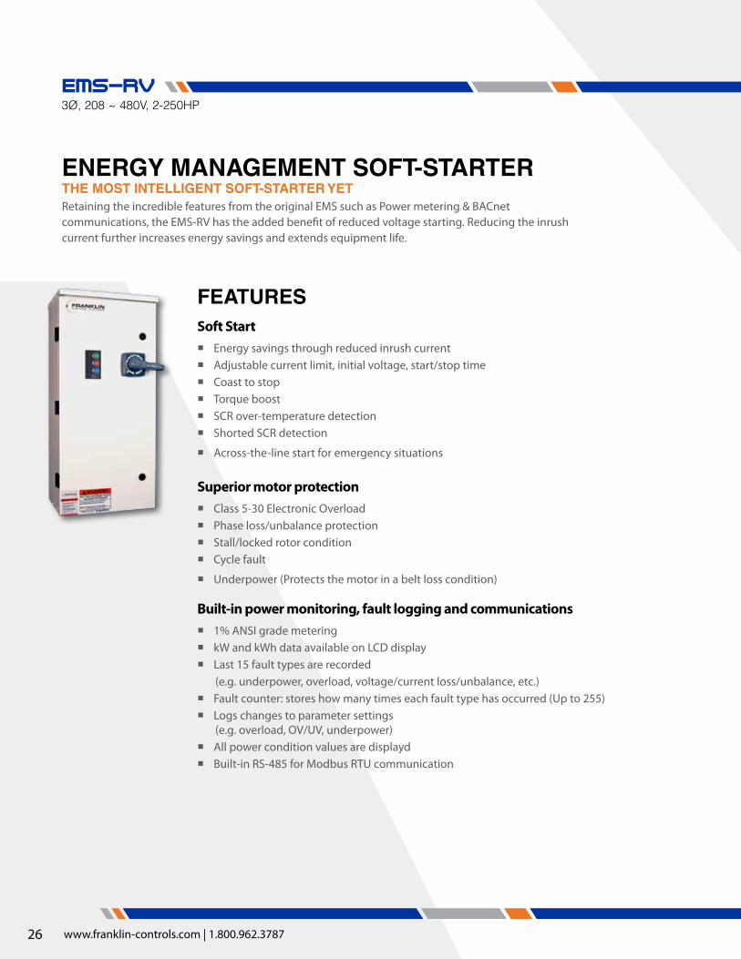
THE MOST INTELLIgENT SOFT-STARTER YETENERgY MANAgEMENT SOFT-STARTER
3Ø, 208 ~ 480V, 2-250HPEMS-RV
Retaining the incredible features from the original EMS such as Power metering & BACnet communications, the EMS-RV has the added benefit of reduced voltage starting. Reducing the inrush current further increases energy savings and extends equipment life.
Soft Start � Energy savings through reduced inrush current � Adjustable current limit, initial voltage, start/stop time � Coast to stop � Torque boost � SCR over-temperature detection � Shorted SCR detection
� Across-the-line start for emergency situations
Superior motor protection � Class 5-30 Electronic Overload � Phase loss/unbalance protection � Stall/locked rotor condition � Cycle fault
� Underpower (Protects the motor in a belt loss condition)
Built-in power monitoring, fault logging and communications � 1% ANSI grade metering � kW and kWh data available on LCD display � Last 15 fault types are recorded
(e.g. underpower, overload, voltage/current loss/unbalance, etc.) � Fault counter: stores how many times each fault type has occurred (Up to 255) � Logs changes to parameter settings
(e.g. overload, OV/UV, underpower) � All power condition values are displayd � Built-in RS-485 for Modbus RTU communication
FEATURES

27
HOA keypad with LCD display � Plain English operation – easy to set up and simple to
operate � LEDs indicate Hand/Off/Auto modes, run and fault
conditions
Building automation system ready � Relay outputs for fault and proof of flow verification
� Detects belt loss and alerts automation system � Eliminates costly current sensors
� Voltage inputs for auto run and fireman’s override (accepts 12-120VAC/DC)
� Wire directly from the automation system to the starter, no interposing relays necessary
� Fireman’s override initiates smoke purge sequence during emergency situations for safety and code compliance
� Dry inputs for auto run, emergency shutdown, and permissive auto (N.O. dry contact closure)
� Analog input for (selectable) 0-10V, 4-20mA, 10k Thermistor, viewable as a Modbus point
Our multi-tap power transformer accepts inputs of: 208, 230, & 460V
<
120V control circuit � Option in lieu of 24VAC standard
Ground fault protection � Protects motors from damage due to ground
current conditions � UL 1053 Certified
Optional circuit breaker disconnect � Molded case circuit breaker provides branch and short
circuit protection � High interrupting ratings for maximum electrical
system compatibility � No fuses required – save time and money � Lockable handle for safety
Multi-tap control power transformer (CPT) � Multi-tap CPT input accepts all common motor
voltages � Integrated secondary protection – no fuses required
OpTIONS
EMS-RV

28
Starter Size H W D
EMS3R-RV-9/J-G15 ~ EMS3R-RV-100/J-G150 32 15 10
EMS3R-RV-150/J-GXXX 36 24 12
EMS3R-RV-330/J-G250 ~ EMS3R-RV-330/J-G400 42 30 12
EMS3R-RV-330/J-G500 ~ EMS3R-RV-400/J-G600 48 30 16
*All measurements in inches
NEMA Type 3R Indoor/Outdoor Enclosure Combination Energy Management Soft Starter - 3-Phase, 208~460VACIncludes Molded Case Circuit Breaker Disconnect
UL Three Phase HP SCIC KAIC @EMS-RV Part Number
208V 230V 460V 208/230V 460V2 2 5 100 65 EMS3R-RV-9/J-G15
3 3 7.5 100 65 EMS3R-RV-18/J-G20
5 5 10 100 65 EMS3R-RV-22/J-G30
5 7.5 15 100 65 EMS3R-RV-32/J-G40
7.5 10 20 100 65 EMS3R-RV-40/J-G50
10 10 25 100 65 EMS3R-RV-40/J-G60
- 15 30 100 65 EMS3R-RV-50/J-G80
15 20 40 100 65 EMS3R-RV-65/J-G100
20 25 50 100 65 EMS3R-RV-85/J-G125
25 30 60 100 65 EMS3R-RV-100/J-G150
30 40 75 100 65 EMS3R-RV-150/J-G200
40 50 100 100 65 EMS3R-RV-150/J-G250
40 50 100 18 18 EMS3R-RV-330/J-G250
50 60 125 18 18 EMS3R-RV-330/J-G300
60 75 150 18 18 EMS3R-RV-330/J-G400
74 100 200 18 18 EMS3R-RV-330/J-G500
100 125 250 18 18 EMS3R-RV-400/J-G600
Options EMS-SRG240 208-240VAC Surge Supressor
EMS-SRG480 480-600VAC Surge Supressor
EMS-GFLT Ground Fault Protection
EMS-120 120VAC Control Circuit
NEMA Type 3R Indoor/Outdoor Enclosure Standard Energy Management Soft Starter - 3-Phase, 208~460VAC
UL Three Phase HP Standard SCIC KAIC @
High Fault*SCIC KAIC @ EMS-RV Part Number
208V 230V 460V 208/230V/460V 208/230V 460V15 15 30 5 100 65 EMS3R-RV-50/J
25 30 60 10 100 65 EMS3R-RV-100/J
40 50 100 10 100 65 EMS3R-RV-150/J
100 125 250 18 18 18 EMS3R-RV-400/J
*A molded case circuit breaker must be used in order to obtain the high fault SCIC KAIC ratings
EMS-RV Options
EMS-RV (Combination)
H
W
D
Starter Size H W D
EMS3R-RV-50/J ~ EMS3R-RV-100/J 32 15 10
EMS3R-RV-150/J 36 24 12
EMS3R-RV-400/J 42 30 12
EMS-RV (Standard)
DIMENSIONS
ORDERINg AND SIzINg INFO

29
H1 H4
L1 L2
T1 T3
L3
T2
43
44
31
32
A B C
CAT 5OLOutput
T3 T1T2
M
3PH
L3 L1L2
SOFT STARTER M
L1 L3L2
T1 T3T2
A1
A2M
EMS-RV PCB1
CommonShutdown(Perm. Auto)Auto Run(Perm. Auto)
Common
Fault
Status
Fireman’sOverride
Auto Run
12-120VAC/DC Input
CAT 5 Input
TRANSFORMER PRIMARYCIRCUIT BREAKER SIZING
VA 208/230 480V50VA100VA 1A 1A
N/A N/A
24VCPT
NOTE: DASHED LINES INDICATE FIELD WIRING
RS-485+
S
-
AnalogInput
A-
A+
DryInputs
D
D4
D3
CAT-5
GATE DRIVE PCB
TempSensor
S1
S2
CAT-5
EMS-RV PCB2
V1
V2
V3
V4
O1
O2
O
D1
D
D2
Voltage Inputs
Relay Outputs
Dry Inputs
12-120VAC/DC Input
N.C. Input
N.O. Input
240V 480V208V120V
H1 H4
T1 T3T2
MCCB(Optional)
JDS-DO NOT REMOVE
EMS-RV WIRINg DIAgRAMEMS-RV

30 www.franklin-controls.com | 1.800.962.3787
EMS-RV SpecificationStarter Type
EMS-RV - Energy Management Starter - Reduced Voltage (Soft Starter)
200-600VAC, 3-Phase, 50/60Hz input, Reduced voltage starter
NEMA Type 3R Enclosed
User Interface
Hand-Off-Auto Door mounted Hand-Off-Auto keypad (water-tight-membrane)
Programming Internal display with programming keys (LCD, back-lit, 16 character)
Mode Indication Integrated LEDs, Hand-Off-Auto-Run-Fault indication
Standard Control Operations
Inputs
Voltage Auto-Run Accepts 12-130VAC/DC. Applying voltage will send a run command to the starter when in Auto mode.
Dry Contact Auto-Run Normally Open dry contact. When closed, the starter will be commanded to run when in Auto mode.
Fireman’s OverrideAccepts 12-130VAC/DC. Applying voltage will command the motor to run in all modes and will supersede a Shutdown com-mand. Hand/Off/Auto/Run/Fault LEDs will flash.
ShutdownNormally Closed dry contact. When open, the contactor will open and the starter will disengage the contactor and will not accept a run command with the exception of Fireman’s Override. Hand/Off/Auto LEDs will flash.
Permissive Auto Normally Open dry contact. When closed, the starter will not accept a run command when in Auto mode.
RS-485 Modbus RTU slave
Analog Input Selectable 0-10V, 4-20mAm 10k Thermistor, viewable as a Modbus point
OutputsStatus Relay Normally Open relay contacts.
Status Relay will close when the motor draws a user defined percentage of the FLA setting.Fault Relay will close in the event of a fault trip.Contact Ratings: 0.3A @ 125VAC, 1A @ 24VACFault Relay
Operational
Starts 6/hour, 20 seconds max start time @ 400% FLA, 30 seconds max start time @ 300@ FLA
Overload Type Electronic, I2t trip curve
Power Fail Modes
Restart in last mode (Hand/Off/Auto) with no delay (default)
Restart in Off mode
Restart in Off mode if power failure lasts longer than 2 seconds. Restart in last mode if power failure is less than 2 seconds.
On/Off Time Delay On/Off, Adjustable: 0.1-99 seconds
Fault Reset Adjustable: Manual or Automatic
Environmental
Ambient Operating Temp -5° to 140° F (-20° to 60° C)
Ambient Storage Temp -5° to 185° F (-20° to 85° C)
Relative Humidity 5% to 95% non-condensing
Motor / Soft Starter Protection Adjustment / Description Default Setting
Overload Current Setting Range Differs per model Per FLA
Overload Trip Class Adjustable: 5-30 10
Overload Service Factor Adjustable: 0.00-2.00 1.15
Under Power On/Off, Adjustable: 0-99% of measured electrical input Off / 80%
Over Power On/Off, Adjustable: 101-200% of measured electrical input Off / 120%
Over / Under Voltage On/Off, Adjustable: +5-25% over/under the nominal voltage setting On / 10%
Voltage Phase Unbalance On/Off, Adjustable: 1-20% voltage phase deviation On / 3%
Voltage Phase Loss Always On, Adjustable: 1-50% voltage phase deviation 5%
Voltage Phase Sequence Reversal On/Off, Trips within 0.1 seconds upon voltage phase reversal detection On
Ground Fault (Optional) On/Off, Adjustable: 1.0-9.9A Off / 1A
Cycle Fault On/Off, Trips if contactor cycle rate exceeds 20 starts/minute On
Warm Start Provision On/Off, Delays motor restart after a fault trip, based on calculated motor temperature On
Current Phase Unbalance On/Off, Adjustable: 1-50% current phase unbalance On / 20%
Locked Rotor / Stall On/Off, Trips within 0.5 seconds On
Shorted SCR Always On, Trips upon detection of a shorted SCR or no motor On
Open SCR Always On, Trips if no current is detected during startup or bypass On
SCR Over-Temperature Always On, Trips if any SCR reaches 125oC On
Across-The-Line Start On/Off, Allows the user to start the motor across-the-line Off
31
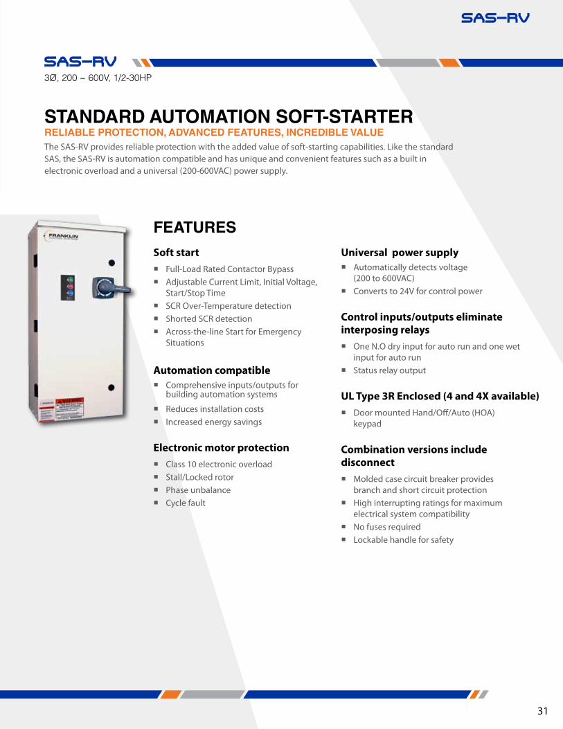
RELIABLE pROTECTION, ADVANCED FEATURES, INCREDIBLE VALUESTANDARD AUTOMATION SOFT-STARTER The SAS-RV provides reliable protection with the added value of soft-starting capabilities. Like the standard SAS, the SAS-RV is automation compatible and has unique and convenient features such as a built in electronic overload and a universal (200-600VAC) power supply.
3Ø, 200 ~ 600V, 1/2-30HP
SAS-RV
Universal power supply � Automatically detects voltage
(200 to 600VAC) � Converts to 24V for control power
Control inputs/outputs eliminate interposing relays
� One N.O dry input for auto run and one wet input for auto run
� Status relay output
UL Type 3R Enclosed (4 and 4X available) � Door mounted Hand/Off/Auto (HOA)
keypad
Combination versions include disconnect
� Molded case circuit breaker provides branch and short circuit protection
� High interrupting ratings for maximum electrical system compatibility
� No fuses required � Lockable handle for safety
Soft start � Full-Load Rated Contactor Bypass � Adjustable Current Limit, Initial Voltage,
Start/Stop Time � SCR Over-Temperature detection � Shorted SCR detection � Across-the-line Start for Emergency
Situations
Automation compatible � Comprehensive inputs/outputs for
building automation systems
� Reduces installation costs � Increased energy savings
Electronic motor protection � Class 10 electronic overload � Stall/Locked rotor � Phase unbalance � Cycle fault
FEATURES
SAS-RV

32 www.franklin-controls.com | 1.800.962.3787
Options SAS-SRG240 208-240V surge supressor
SAS-SRG480 480-600V surge supressor
Starter Size H W D
SAS3R-RV-9 ~ SAS3R-RV-50 22 15 10
SAS3R-RV-65 ~ SAS3R-RV-100 32 15 10
*All measurements in inches
UL/NEMA Type 3R Outdoor Enclosure Combination Standard Automation Soft Starter - 3-Phase, 200~575VACIncludes Molded Case Circuit Breaker Disconnect
UL Three Phase HP SCIC KAIC @SAS-RV Part Number
208V 230V 460V 575V 200/230V 460V 600V2 2 5 5 100 65 14 SAS3R-RV-9/J-G15
3 3 7.5 10 100 65 14 SAS3R-RV-18/J-G20
5 5 10 15 100 65 14 SAS3R-RV-22/J-G30
5 7.5 15 20 100 65 14 SAS3R-RV-32/J-G40
7.5 10 20 25 100 65 14 SAS3R-RV-40/J-G50
10 10 25 30 100 65 14 SAS3R-RV-40/J-G60
- 15 30 40 100 65 14 SAS3R-RV-50/J-G80
15 20 40 50 100 65 14 SAS3R-RV-65/J-G100
20 25 50 60 100 65 14 SAS3R-RV-85/J-G125
25 30 60 75 100 65 18 SAS3R-RV-100/J-G150
UL/NEMA Type 3R Outdoor Enclosure Standard Automation Soft Starter - 3-Phase, 200~575VAC
UL Three Phase HP Standard SCIC KAIC @
High Fault*SCIC KAIC @ SAS-RV Part
Number208V 230V 460V 575VHP HP HP HP 200/230V/460V 200/230V 460V 600V2 2 5 7.5 5 100 65 14 SAS3R-RV-9/J
5 5 10 15 5 100 65 14 SAS3R-RV-18/J
7.5 10 20 25 5 100 65 14 SAS3R-RV-32/J
10 10 30 30 5 100 65 14 SAS3R-RV-40/J
15 15 30 40 5 100 65 14 SAS3R-RV-50/J
25 30 60 75 10 100 65 18 SAS3R-RV-100/J
*A molded case circuit breaker must be used in order to obtain the high fault SCIC KAIC ratings
SAS-RV Options
SAS-RV (All)
H
W
D
DIMENSIONS
ORDERINg AND SIzINg INFO

33
NOTE: DASHED LINES INDICATE FIELD WIRING
SAS-RVPOWER WIRING
A1
A2M
SAS-RV CONTROL WIRING
DryInput
Relay Output Status
Auto Run
VoltageInput
ContactorCoil
1
FLA (A)
23
4 5
6
7
8
9
PCB Power
H1 H4
Auto Run 12-250VAC/DC Input
Keypad
Overload Setting(Reference Only)
Normally Open Input
24V Output to contactor coil
CAT-5
GATE DRIVE PCB
TempSensor
S1
S2
CAT-5
D2D1
V1
V2
O1O2
C-
C+
ST
OP
TIM
E
ST
AR
TT
IME
CU
RR
EN
TLI
MIT
INIT
IAL
VO
LTA
GE
%
%
100 400
10 70
250
40
175 325
5
25 55
0.2 30seconds
152010
25
2 30seconds
15
5
201025
L1 L2
T1 T3
L3
T2
43
44
31
32
OL
T3 T1T2
M
3PH
L3 L1L2
T1 T3T2
SOFT STARTER
H1 H4
M
L1 L3L2
T1 T3T2
MCCB(Optional)
SAS-RV WIRINg DIAgRAM
SAS-RV SpecificationStarter Type
SAS-RV - Standard Automation Starter - Reduced Voltage (Soft Starter)
200-600VAC, 3-Phase, 50/60Hz input, Reduced voltage starter
NEMA Type 3R Enclosed
User Interface
Hand-Off-Auto Door mounted Hand-Off-Auto keypad (water-tight-membrane)
Programming Internal dials
Mode Indication Integrated LEDs, Hand-Off-Auto-Run-Fault indication
Standard Control Operations
InputsVoltage Atuo-Run Accepts 12-130VAC/DC. Applying voltage will send a run command to the starter when in Auto mode.
Dry Contact Auto-Run Normally Open dry contact. When closed, the starter will be commanded to run when in Auto mode.
Output Status RelayNormally Open relay contact. Status Relay will close when the motor draws a user defined percentage of the FLA setting.Contact Ratings: 0.3A @ 125VAC, 1A @ 24VAC
Operational
Starts 6/hour, 20 seconds max start time @ 400% FLA, 30 seconds max start time @ 300@ FLA
Overload Type Electronic, I2t trip curve
Power Fail Modes Restart in last mode (Hand/Off/Auto) with no delay (default)
Fault Reset Adjustable: Manual or Automatic
Environmental
Ambient Operating Temp -5° to 140° F (-20° to 60° C)
Ambient Storage Temp -5° to 185° F (-20° to 85° C)
Relative Humidity 5% to 95% non-condensing
Motor / Soft Starter Protection Adjustment / Description Default Setting
Overload Current Setting Range Differs per model Per FLA
Overload Trip Class Class 10, Trip current = 115% of FLA setting 10
Overload Service Factor 1.15 1.15
Cycle Fault Always On,, Trips if contactor cycle rate exceeds 20 starts/minute On
Current Phase Unbalance Always On, Trips @ 50% current phase unbalance 50%
Locked Rotor / Stall Always On,, Trips within 0.5 seconds On
Shorted SCR Always On, Trips upon detection of a shorted SCR or no motor On
Open SCR Always On, Trips if no current is detected during startup or bypass On
SCR Over-Temperature Always On, Trips if any SCR reaches 125oC On
Across-The-Line Start On/Off, Allows the user to start the motor across-the-line Off
SAS-RV

34 www.franklin-controls.com | 1.800.962.3787
“FCS takes care of problems without having to jump through hoops and tons of paperwork to get the end customer taken care of.”
“Great customer service on a hot rush job...we were able to order in time to ship same day to keep the customer’s job on track!”
WE’RE CUSTOMER DRIVEN, BUT DON’T TAKE OUR WORD FOR IT. HERE ARE A FEW gENUINE qUOTES FROM OUR CUSTOMER SATISFACTION SURVEY:
“Many companies could learn from the way you do business. The response when the order is placed, tracking sent when the item ships, all this makes for an excellent customer service experience.”

About UsAs the leading provider of intelligent HVAC motor controls, we like challenging conventional wisdom. We’re always seeking to increase equipment life, enhance usability, and intelligently manage energy. You’ll find evidence of our results in world class installations – from schools, universities, and military bases to sports venues, museums, and commercial buildings. Franklin Control Systems (FCS) products are manufactured to the highest quality standards within a UL 508 facility based in Portland, Oregon.
Smart Products. Smart Dealers.With representation in every major North American market, FCS Dealers are your source for motor controls. Our dealers are the local resource for building owners, design engineers, and HVAC contractors within the markets we serve. Our partners are factory trained to offer localized service, product education and support. Our dealer reps provide equipment selection assistance, quotations, design and installation recommendations as well as
parts and warranty assistance. To locate a dealer within your area, please visit www.franklin-controls.com.
Made in the USABuilt in America, Franklin Control Systems Products uphold their title of value, building confidence and peace of mind for the owner, installer, and end user.
Franklin Control Systems Proudly Offers Same-Day Shipping.
Promoting Energy SavingsWith our Smart Starters, Franklin Control Systems is committed to saving energy and creating more sustainable buildings.
©2014 Franklin Control Systems
OVER 90% OF OUR CUSTOMERS RATE THEIR ExpERIENCE WITH FRANKLIN CONTROL SYSTEMS AN 8/10 OR HIgHER!

36 www.franklin-controls.com | 1.800.962.3787
A FRANKLIN ELECTRIC COMPANY22985 NW EVERGREEN PKWY, HILLSBORO, OR 97124
Phone: 800.962.3787FRANKLIN-CONTROLS.COM
BROCHURE-HVAC-STRVERSION 1 - 2014


