83
Smart Water Technical Guide wasp m o te
Smart WaterTechnical Guide
waspmote
-2- v7.4
Index
Document version: v7.3 - 06/2018 © Libelium Comunicaciones Distribuidas S.L.
INDEX1. General ...................................................................................................................................5
1.1. General and safety information ...................................................................................................... 51.2. Conditions of use .............................................................................................................................. 6
2. New version: Smart Water v3.0 ...........................................................................................7
3. Waspmote Plug & Sense! ......................................................................................................83.1. Features ............................................................................................................................................. 83.2. General view ...................................................................................................................................... 9
3.2.1. Specifications .........................................................................................................................93.2.2. Parts included ......................................................................................................................123.2.3. Identification ........................................................................................................................13
3.3. Sensor probes ................................................................................................................................. 153.4. Solar powered ................................................................................................................................. 163.6. Programming the Nodes ................................................................................................................ 183.7. Radio interfaces............................................................................................................................... 193.8. Industrial Protocols ......................................................................................................................... 203.9. GPS .................................................................................................................................................... 223.10. Models ............................................................................................................................................ 23
3.10.1. Smart Water .......................................................................................................................243.10.2. Smart Water Ions ..............................................................................................................263.10.3. Smart Security ...................................................................................................................29
4. Hardware .............................................................................................................................314.1. General description ........................................................................................................................ 314.2. Specifications ................................................................................................................................... 314.3. Electrical Characteristics ................................................................................................................ 31
5. Sensors .................................................................................................................................325.1. Temperature Sensor (Pt-1000) ...................................................................................................... 32
5.1.1. Specifications .......................................................................................................................325.1.2. Measurement Process ........................................................................................................325.1.3. Socket ...................................................................................................................................33
5.2. Conductivity sensor ........................................................................................................................ 345.2.1. Specifications .......................................................................................................................345.2.2. Measurement Process ........................................................................................................345.2.3. Socket ...................................................................................................................................355.2.4. Calibration procedure .........................................................................................................35
-3- v7.4
5.3. Dissolved Oxygen sensor ............................................................................................................... 385.3.1. Specifications .......................................................................................................................385.3.2. Measurement process ........................................................................................................385.3.3. Socket ...................................................................................................................................395.3.4. Calibration procedure .........................................................................................................39
5.4. pH sensor ......................................................................................................................................... 415.4.1. Specifications .......................................................................................................................415.4.2. Measurement Process ........................................................................................................415.4.3. Socket ..................................................................................................................................425.4.4. Calibration procedure .........................................................................................................42
5.5. Oxidation-reduction potential sensor .......................................................................................... 455.5.1. Specifications .......................................................................................................................455.5.2. Measurement process ........................................................................................................455.5.3. Socket ...................................................................................................................................465.5.4. Calibration procedure .........................................................................................................46
5.6. Turbidity sensor .............................................................................................................................. 485.6.1. Specifications .......................................................................................................................485.6.2. Turbidity socket ...................................................................................................................485.6.3. Turbidity: the parameter ....................................................................................................495.6.4. Measurement process ........................................................................................................495.6.5. Calibration of the sensor ....................................................................................................50
5.7. Calibration solutions ....................................................................................................................... 515.8. General considerations about probes performance and life expectancy ............................... 54
6. Board configuration and programming ...........................................................................586.1. Hardware configuration ................................................................................................................. 586.2. Library .............................................................................................................................................. 59
7. Consumption .......................................................................................................................617.1. Power control .................................................................................................................................. 617.2. Tables of consumption ................................................................................................................... 617.3. Low consumption mode ................................................................................................................ 61
8. Safety guides .......................................................................................................................628.1. pH 4.00 Calibration Solution .......................................................................................................... 628.2. pH 7.00 Calibration Solution ......................................................................................................... 658.3. pH 10.00 Calibration Solution ....................................................................................................... 688.4. 0% Dissolved Oxygen Calibration Solution .................................................................................. 718.5. ORP 225mV Calibration Solution .................................................................................................. 748.6. Conductivity K=0.1, 1, 10 Calibration Solutions ........................................................................... 76
Index

-4-
v7.4
9. API changelog ......................................................................................................................79
10. Documentation changelog ..............................................................................................80
11. Certifications .....................................................................................................................81
12. Maintenance ......................................................................................................................82
13. Disposal and recycling ......................................................................................................83
-5- v7.4
General
1. GeneralImportant:
• All documents and any examples they contain are provided as-is and are subject to change without notice. Except to the extent prohibited by law, Libelium makes no express or implied representation or warranty of any kind with regard to the documents, and specifically disclaims the implied warranties and conditions of merchantability and fitness for a particular purpose.
• The information on Libelium’s websites has been included in good faith for general informational purposes only. It should not be relied upon for any specific purpose and no representation or warranty is given as to its accuracy or completeness.
1.1. General and safety information • In this section, the term “Waspmote” encompasses both the Waspmote device itself and its modules and
sensor boards. • Read through the document “General Conditions of Libelium Sale and Use”. • Do not allow contact of metallic objects with the electronic part to avoid injuries and burns. • NEVER submerge the device in any liquid. • Keep the device in a dry place and away from any liquid which may spill. • Waspmote consists of highly sensitive electronics which is accessible to the exterior, handle with great care
and avoid bangs or hard brushing against surfaces. • Check the product specifications section for the maximum allowed power voltage and amperage range and
consequently always use a current transformer and a battery which works within that range. Libelium is only responsible for the correct operation of the device with the batteries, power supplies and chargers which it supplies.
• Keep the device within the specified range of temperatures in the specifications section. • Do not connect or power the device with damaged cables or batteries. • Place the device in a place only accessible to maintenance personnel (a restricted area). • Keep children away from the device in all circumstances. • If there is an electrical failure, disconnect the main switch immediately and disconnect that battery or any
other power supply that is being used. • If using a car lighter as a power supply, be sure to respect the voltage and current data specified in the “Power
Supplies” section. • If using a battery in combination or not with a solar panel as a power supply, be sure to use the voltage and
current data specified in the “Power supplies” section. • If a software or hardware failure occurs, consult the Libelium Web Development section. • Check that the frequency and power of the communication radio modules together with the integrated
antennas are allowed in the area where you want to use the device. • Waspmote is a device to be integrated in a casing so that it is protected from environmental conditions such
as light, dust, humidity or sudden changes in temperature. The board supplied “as is” is not recommended for a final installation as the electronic components are open to the air and may be damaged.
-6- v7.4
General
1.2. Conditions of use • Read the “General and Safety Information” section carefully and keep the manual for future consultation. • Use Waspmote in accordance with the electrical specifications and the environment described in the “Electrical
Data” section of this manual. • Waspmote and its components and modules are supplied as electronic boards to be integrated within a final
product. This product must contain an enclosure to protect it from dust, humidity and other environmental interactions. In the event of outside use, this enclosure must be rated at least IP-65.
• Do not place Waspmote in contact with metallic surfaces; they could cause short-circuits which will permanently damage it.
Further information you may need can be found at: http://www.libelium.com/development/waspmote
The “General Conditions of Libelium Sale and Use” document can be found at:http://www.libelium.com/development/waspmote/technical_service
-7- v7.4
New version: Smart Water v3.0
2. New version: Smart Water v3.0This guide explains the new Smart Water sensor board v3.0. This board was specifically designed for our new product lines Waspmote v15 and Plug & Sense! v15, released on October 2016.
This board is not compatible with Waspmote v12 or Plug & Sense! v12, so it is NOT recommended to mix product generations. If you are using previous versions of our products, please use the corresponding guides, available on our Development website.
You can get more information about the generation change on the document “New generation of Libelium product lines”.
Differences of Smart Water v3.0 with previous versions:
• The old ion sensor circuitry is removed. Now there is a dedicated sensor board for this kind of sensors. • Now the turbidity sensor circuitry is plugged directly to the Smart Water sensor board, avoiding the need of
using an external RS-485 module to use the turbidity sensor. This fact simplifies the sensor connection and leaves free the socket 0 of Waspmote to include another radio module.
• The on-board connector for the Conductivity sensor has been replaced by an SMA connector to make the connection to the board easier and reducing the electrical noise in the measurements.
-8-
v7.4
Waspmote Plug & Sense!
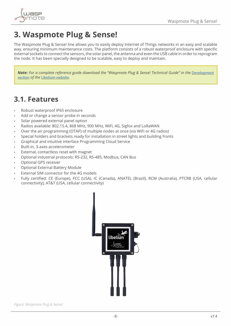
3. Waspmote Plug & Sense!The Waspmote Plug & Sense! line allows you to easily deploy Internet of Things networks in an easy and scalable way, ensuring minimum maintenance costs. The platform consists of a robust waterproof enclosure with specific external sockets to connect the sensors, the solar panel, the antenna and even the USB cable in order to reprogram the node. It has been specially designed to be scalable, easy to deploy and maintain.
Note: For a complete reference guide download the “Waspmote Plug & Sense! Technical Guide” in the Development section of the Libelium website.
3.1. Features • Robust waterproof IP65 enclosure • Add or change a sensor probe in seconds • Solar powered external panel option • Radios available: 802.15.4, 868 MHz, 900 MHz, WiFi, 4G, Sigfox and LoRaWAN • Over the air programming (OTAP) of multiple nodes at once (via WiFi or 4G radios) • Special holders and brackets ready for installation in street lights and building fronts • Graphical and intuitive interface Programming Cloud Service • Built-in, 3-axes accelerometer • External, contactless reset with magnet • Optional industrial protocols: RS-232, RS-485, Modbus, CAN Bus • Optional GPS receiver • Optional External Battery Module • External SIM connector for the 4G models • Fully certified: CE (Europe), FCC (USA), IC (Canada), ANATEL (Brazil), RCM (Australia), PTCRB (USA, cellular
connectivity), AT&T (USA, cellular connectivity)
Figure: Waspmote Plug & Sense!
-9- v7.4
Waspmote Plug & Sense!
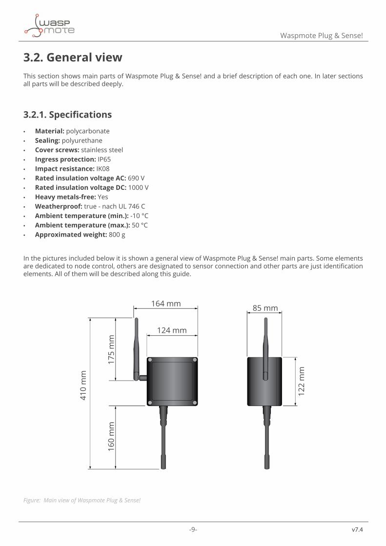
3.2. General viewThis section shows main parts of Waspmote Plug & Sense! and a brief description of each one. In later sections all parts will be described deeply.
3.2.1. Specifications
• Material: polycarbonate • Sealing: polyurethane • Cover screws: stainless steel • Ingress protection: IP65 • Impact resistance: IK08 • Rated insulation voltage AC: 690 V • Rated insulation voltage DC: 1000 V • Heavy metals-free: Yes • Weatherproof: true - nach UL 746 C • Ambient temperature (min.): -10 °C • Ambient temperature (max.): 50 °C • Approximated weight: 800 g
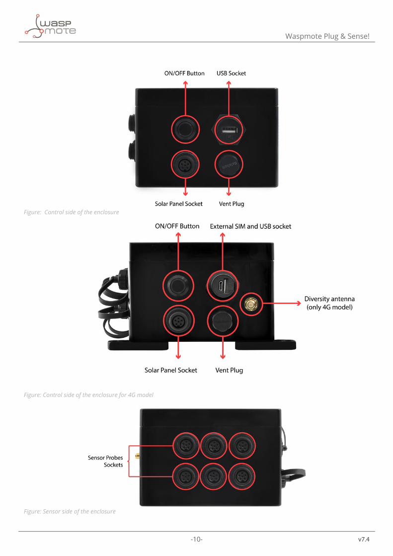
In the pictures included below it is shown a general view of Waspmote Plug & Sense! main parts. Some elements are dedicated to node control, others are designated to sensor connection and other parts are just identification elements. All of them will be described along this guide.
164 mm
124 mm
175
mm
410
mm
160
mm
122
mm
85 mm
Figure: Main view of Waspmote Plug & Sense!
-10- v7.4
Waspmote Plug & Sense!
Figure: Control side of the enclosure
Figure: Control side of the enclosure for 4G model
Figure: Sensor side of the enclosure
-11- v7.4
Waspmote Plug & Sense!
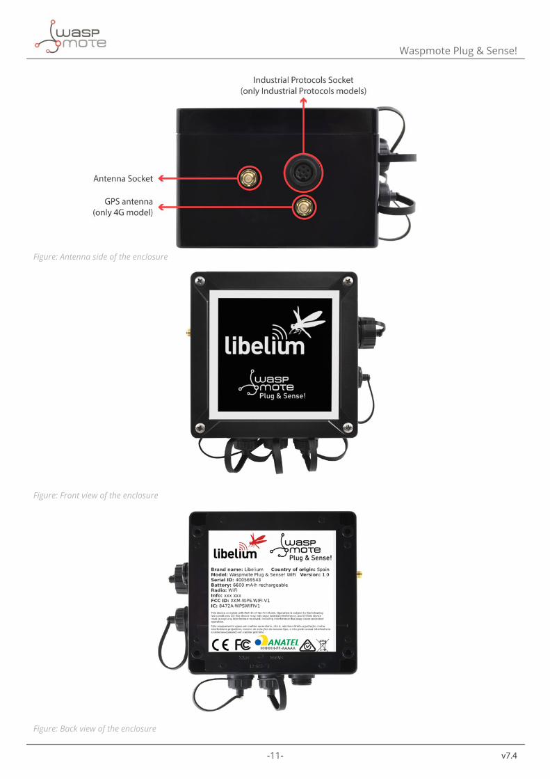
Figure: Antenna side of the enclosure
Figure: Front view of the enclosure
Figure: Back view of the enclosure
-12- v7.4
Waspmote Plug & Sense!
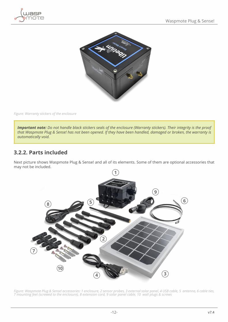
Figure: Warranty stickers of the enclosure
Important note: Do not handle black stickers seals of the enclosure (Warranty stickers). Their integrity is the proof that Waspmote Plug & Sense! has not been opened. If they have been handled, damaged or broken, the warranty is automatically void.
3.2.2. Parts included
Next picture shows Waspmote Plug & Sense! and all of its elements. Some of them are optional accessories that may not be included.
1
2
34
5
7
68
9
10
Figure: Waspmote Plug & Sense! accessories: 1 enclosure, 2 sensor probes, 3 external solar panel, 4 USB cable, 5 antenna, 6 cable ties, 7 mounting feet (screwed to the enclosure), 8 extension cord, 9 solar panel cable, 10 wall plugs & screws
-13- v7.4
Waspmote Plug & Sense!
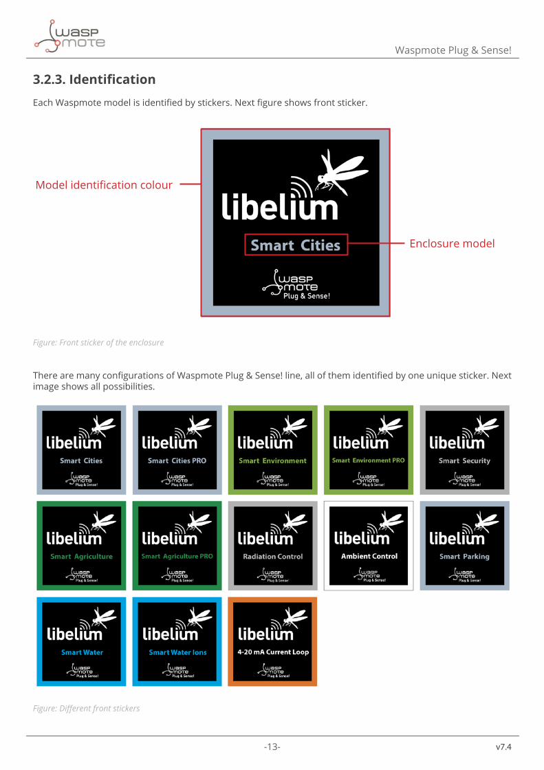
3.2.3. Identification
Each Waspmote model is identified by stickers. Next figure shows front sticker.
Model identification colour
Enclosure model
Figure: Front sticker of the enclosure
There are many configurations of Waspmote Plug & Sense! line, all of them identified by one unique sticker. Next image shows all possibilities.
Figure: Different front stickers
-14- v7.4
Waspmote Plug & Sense!
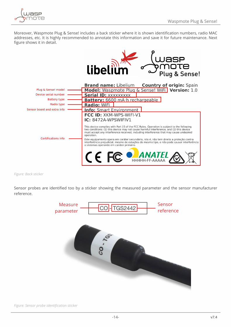
Moreover, Waspmote Plug & Sense! includes a back sticker where it is shown identification numbers, radio MAC addresses, etc. It is highly recommended to annotate this information and save it for future maintenance. Next figure shows it in detail.
Figure: Back sticker
Sensor probes are identified too by a sticker showing the measured parameter and the sensor manufacturer reference.
CO - TGS2442Measure
parameterSensor reference
Figure: Sensor probe identification sticker
-15- v7.4
Waspmote Plug & Sense!
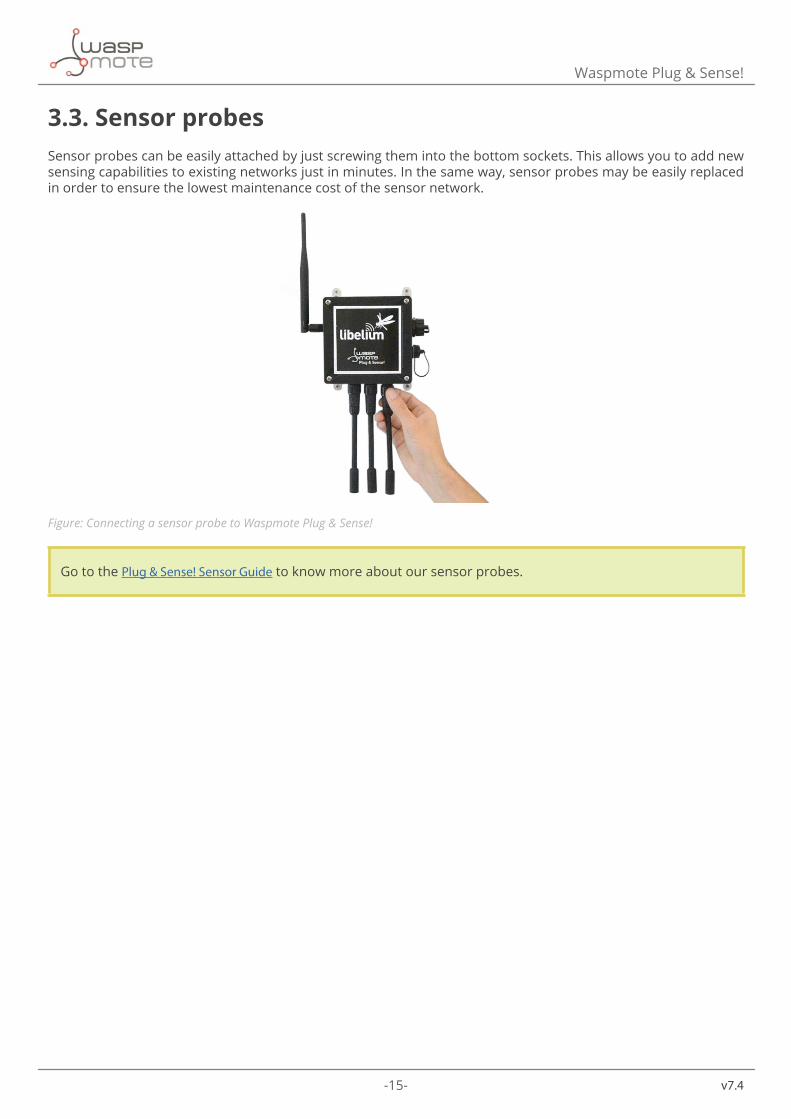
3.3. Sensor probesSensor probes can be easily attached by just screwing them into the bottom sockets. This allows you to add new sensing capabilities to existing networks just in minutes. In the same way, sensor probes may be easily replaced in order to ensure the lowest maintenance cost of the sensor network.
Figure: Connecting a sensor probe to Waspmote Plug & Sense!
Go to the Plug & Sense! Sensor Guide to know more about our sensor probes.
-16- v7.4
Waspmote Plug & Sense!
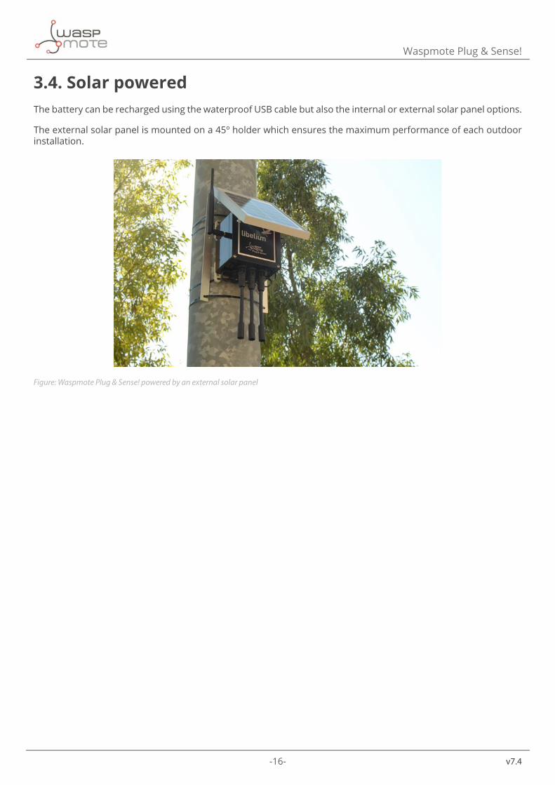
3.4. Solar poweredThe battery can be recharged using the waterproof USB cable but also the internal or external solar panel options.
The external solar panel is mounted on a 45º holder which ensures the maximum performance of each outdoor installation.
Figure: Waspmote Plug & Sense! powered by an external solar panel
-17- v7.4
Waspmote Plug & Sense!
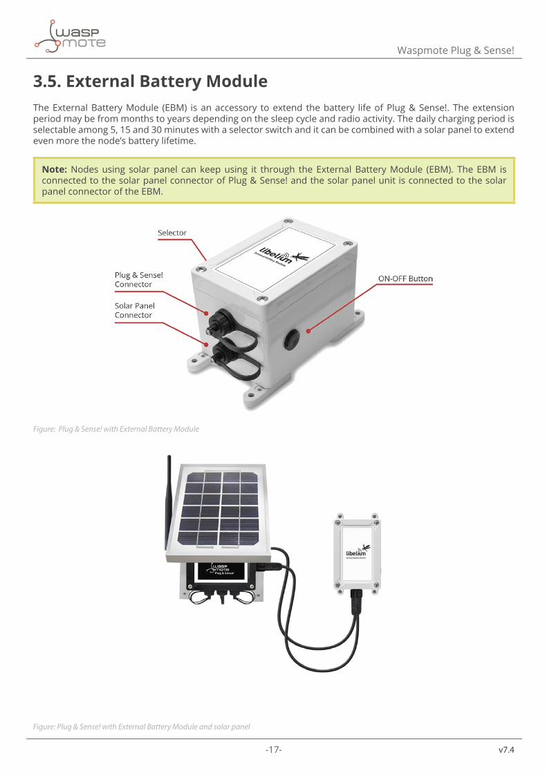
3.5. External Battery ModuleThe External Battery Module (EBM) is an accessory to extend the battery life of Plug & Sense!. The extension period may be from months to years depending on the sleep cycle and radio activity. The daily charging period is selectable among 5, 15 and 30 minutes with a selector switch and it can be combined with a solar panel to extend even more the node’s battery lifetime.
Note: Nodes using solar panel can keep using it through the External Battery Module (EBM). The EBM is connected to the solar panel connector of Plug & Sense! and the solar panel unit is connected to the solar panel connector of the EBM.
Figure: Plug & Sense! with External Battery Module
Figure: Plug & Sense! with External Battery Module and solar panel
-18- v7.4
Waspmote Plug & Sense!
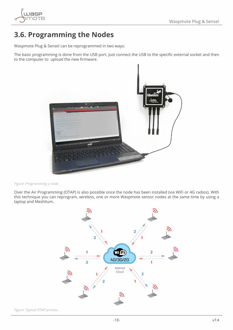
3.6. Programming the NodesWaspmote Plug & Sense! can be reprogrammed in two ways:
The basic programming is done from the USB port. Just connect the USB to the specific external socket and then to the computer to upload the new firmware.
Figure: Programming a node
Over the Air Programming (OTAP) is also possible once the node has been installed (via WiFi or 4G radios). With this technique you can reprogram, wireless, one or more Waspmote sensor nodes at the same time by using a laptop and Meshlium.
Figure: Typical OTAP process
-19- v7.4
Waspmote Plug & Sense!
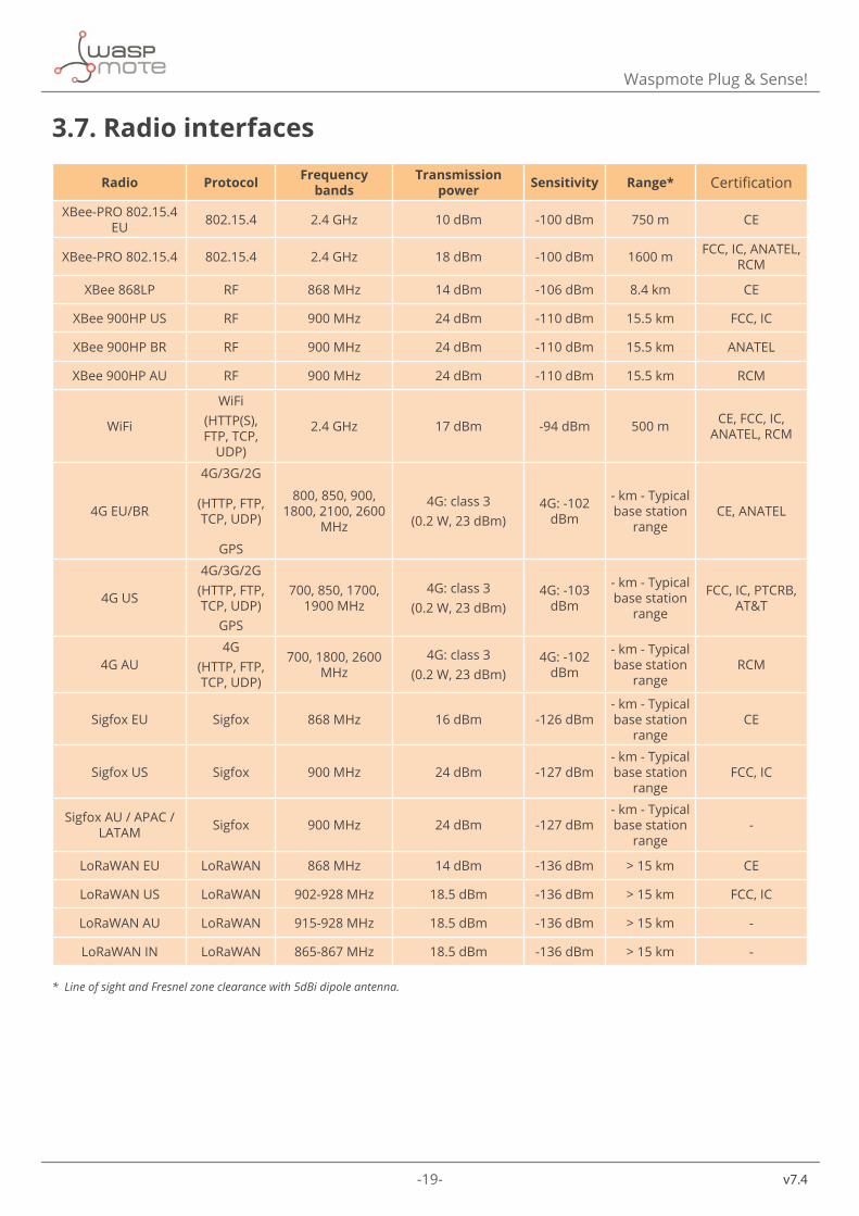
3.7. Radio interfaces
Radio Protocol Frequency bands
Transmission power Sensitivity Range* Certification
XBee-PRO 802.15.4 EU 802.15.4 2.4 GHz 10 dBm -100 dBm 750 m CE
XBee-PRO 802.15.4 802.15.4 2.4 GHz 18 dBm -100 dBm 1600 m FCC, IC, ANATEL, RCM
XBee 868LP RF 868 MHz 14 dBm -106 dBm 8.4 km CE
XBee 900HP US RF 900 MHz 24 dBm -110 dBm 15.5 km FCC, IC
XBee 900HP BR RF 900 MHz 24 dBm -110 dBm 15.5 km ANATEL
XBee 900HP AU RF 900 MHz 24 dBm -110 dBm 15.5 km RCM
WiFi
WiFi(HTTP(S), FTP, TCP,
UDP)
2.4 GHz 17 dBm -94 dBm 500 m CE, FCC, IC, ANATEL, RCM
4G EU/BR
4G/3G/2G
(HTTP, FTP, TCP, UDP)
GPS
800, 850, 900, 1800, 2100, 2600
MHz
4G: class 3 (0.2 W, 23 dBm)
4G: -102 dBm
- km - Typical base station
rangeCE, ANATEL
4G US
4G/3G/2G(HTTP, FTP, TCP, UDP)
GPS
700, 850, 1700, 1900 MHz
4G: class 3 (0.2 W, 23 dBm)
4G: -103 dBm
- km - Typical base station
range
FCC, IC, PTCRB, AT&T
4G AU4G
(HTTP, FTP, TCP, UDP)
700, 1800, 2600 MHz
4G: class 3 (0.2 W, 23 dBm)
4G: -102 dBm
- km - Typical base station
rangeRCM
Sigfox EU Sigfox 868 MHz 16 dBm -126 dBm- km - Typical base station
rangeCE
Sigfox US Sigfox 900 MHz 24 dBm -127 dBm- km - Typical base station
rangeFCC, IC
Sigfox AU / APAC / LATAM Sigfox 900 MHz 24 dBm -127 dBm
- km - Typical base station
range-
LoRaWAN EU LoRaWAN 868 MHz 14 dBm -136 dBm > 15 km CE
LoRaWAN US LoRaWAN 902-928 MHz 18.5 dBm -136 dBm > 15 km FCC, IC
LoRaWAN AU LoRaWAN 915-928 MHz 18.5 dBm -136 dBm > 15 km -
LoRaWAN IN LoRaWAN 865-867 MHz 18.5 dBm -136 dBm > 15 km -
* Line of sight and Fresnel zone clearance with 5dBi dipole antenna.

-20- v7.4
Waspmote Plug & Sense!
3.8. Industrial ProtocolsBesides the main radio of Waspmote Plug & Sense!, it is possible to have an Industrial Protocol module as a secondary communication option. This is offered as an accessory feature.
The available Industrial Protocols are RS-232, RS-485, Modbus (software layer over RS-232 or RS-485) and CAN Bus. This optional feature is accessible through an additional, dedicated socket on the antenna side of the enclosure.
Figure: Industrial Protocols available on Plug & Sense!
-21- v7.4
Waspmote Plug & Sense!
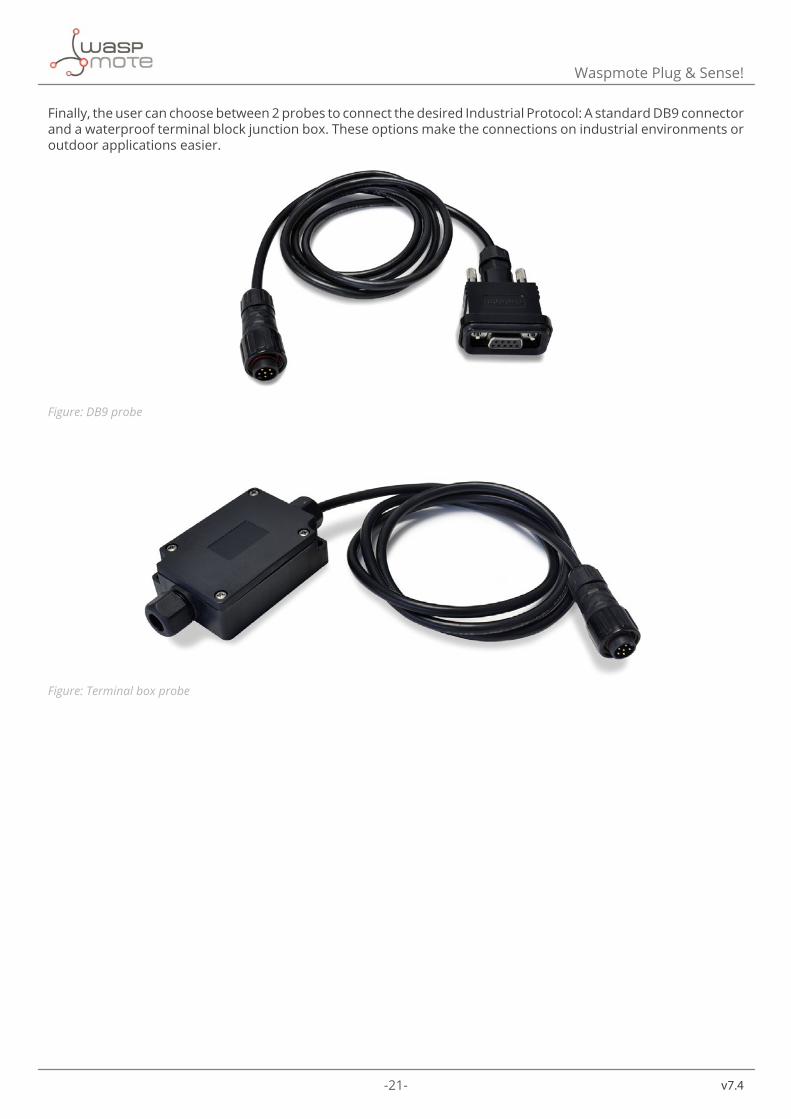
Finally, the user can choose between 2 probes to connect the desired Industrial Protocol: A standard DB9 connector and a waterproof terminal block junction box. These options make the connections on industrial environments or outdoor applications easier.
Figure: DB9 probe
Figure: Terminal box probe
-22- v7.4
Waspmote Plug & Sense!
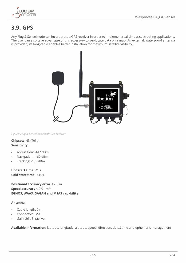
3.9. GPSAny Plug & Sense! node can incorporate a GPS receiver in order to implement real-time asset tracking applications. The user can also take advantage of this accessory to geolocate data on a map. An external, waterproof antenna is provided; its long cable enables better installation for maximum satellite visibility.
Figure: Plug & Sense! node with GPS receiver
Chipset: JN3 (Telit)Sensitivity:
• Acquisition: -147 dBm • Navigation: -160 dBm • Tracking: -163 dBm
Hot start time: <1 sCold start time: <35 s
Positional accuracy error < 2.5 mSpeed accuracy < 0.01 m/sEGNOS, WAAS, GAGAN and MSAS capability
Antenna:
• Cable length: 2 m • Connector: SMA • Gain: 26 dBi (active)
Available information: latitude, longitude, altitude, speed, direction, date&time and ephemeris management
-23- v7.4
Waspmote Plug & Sense!
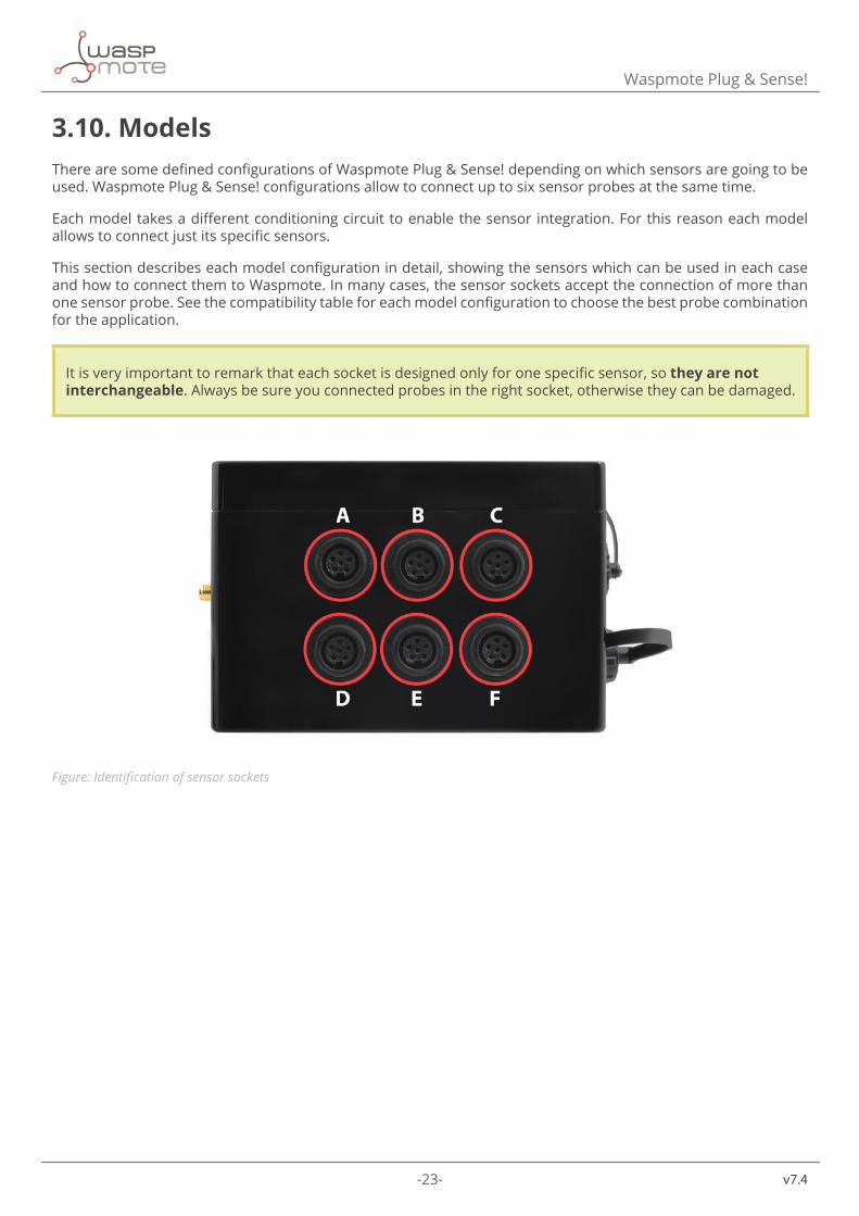
3.10. ModelsThere are some defined configurations of Waspmote Plug & Sense! depending on which sensors are going to be used. Waspmote Plug & Sense! configurations allow to connect up to six sensor probes at the same time.
Each model takes a different conditioning circuit to enable the sensor integration. For this reason each model allows to connect just its specific sensors.
This section describes each model configuration in detail, showing the sensors which can be used in each case and how to connect them to Waspmote. In many cases, the sensor sockets accept the connection of more than one sensor probe. See the compatibility table for each model configuration to choose the best probe combination for the application.
It is very important to remark that each socket is designed only for one specific sensor, so they are not interchangeable. Always be sure you connected probes in the right socket, otherwise they can be damaged.
Figure: Identification of sensor sockets
-24- v7.4
Waspmote Plug & Sense!
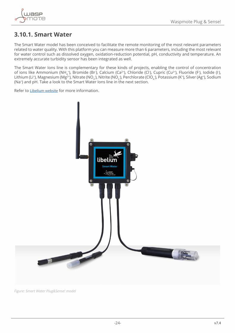
3.10.1. Smart WaterThe Smart Water model has been conceived to facilitate the remote monitoring of the most relevant parameters related to water quality. With this platform you can measure more than 6 parameters, including the most relevant for water control such as dissolved oxygen, oxidation-reduction potential, pH, conductivity and temperature. An extremely accurate turbidity sensor has been integrated as well.
The Smart Water Ions line is complementary for these kinds of projects, enabling the control of concentration of ions like Ammonium (NH4
+), Bromide (Br-), Calcium (Ca2+), Chloride (Cl-), Cupric (Cu2+), Fluoride (F-), Iodide (I-), Lithium (Li+), Magnesium (Mg2+), Nitrate (NO3
-), Nitrite (NO2-), Perchlorate (ClO4
-), Potassium (K+), Silver (Ag+), Sodium (Na+) and pH. Take a look to the Smart Water Ions line in the next section.
Refer to Libelium website for more information.
Figure: Smart Water Plug&Sense! model

-25- v7.4
Waspmote Plug & Sense!
Sensor sockets are configured as shown in the figure below.
Sensor Socket
Sensor probes allowed for each sensor socketParameter Reference
A pH 9328B Dissolved Oxygen (DO) 9327C Conductivity 9326E Oxidation-Reduction Potential (ORP) 9329
FSoil/Water Temperature 9255-P (included by default)Turbidity 9353-P
Figure: Sensor sockets configuration for Smart Water model
Note: For more technical information about each sensor probe go to the Development section on the Libelium website.
-26- v7.4
Waspmote Plug & Sense!
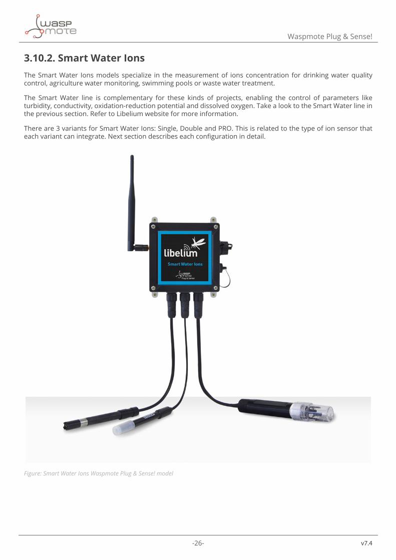
3.10.2. Smart Water IonsThe Smart Water Ions models specialize in the measurement of ions concentration for drinking water quality control, agriculture water monitoring, swimming pools or waste water treatment.
The Smart Water line is complementary for these kinds of projects, enabling the control of parameters like turbidity, conductivity, oxidation-reduction potential and dissolved oxygen. Take a look to the Smart Water line in the previous section. Refer to Libelium website for more information.
There are 3 variants for Smart Water Ions: Single, Double and PRO. This is related to the type of ion sensor that each variant can integrate. Next section describes each configuration in detail.
Figure: Smart Water Ions Waspmote Plug & Sense! model
-27- v7.4
Waspmote Plug & Sense!
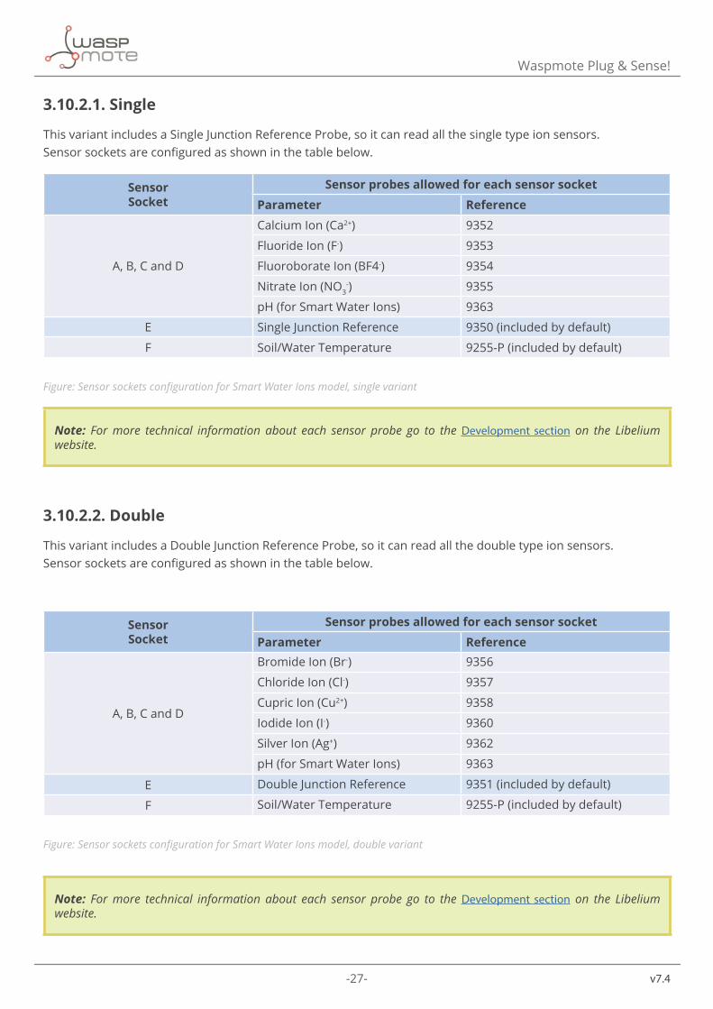
3.10.2.1. Single
This variant includes a Single Junction Reference Probe, so it can read all the single type ion sensors. Sensor sockets are configured as shown in the table below.
SensorSocket
Sensor probes allowed for each sensor socketParameter Reference
A, B, C and D
Calcium Ion (Ca2+) 9352
Fluoride Ion (F-) 9353
Fluoroborate Ion (BF4-) 9354
Nitrate Ion (NO3-) 9355
pH (for Smart Water Ions) 9363
E Single Junction Reference 9350 (included by default)
F Soil/Water Temperature 9255-P (included by default)
Figure: Sensor sockets configuration for Smart Water Ions model, single variant
Note: For more technical information about each sensor probe go to the Development section on the Libelium website.
3.10.2.2. Double
This variant includes a Double Junction Reference Probe, so it can read all the double type ion sensors. Sensor sockets are configured as shown in the table below.
SensorSocket
Sensor probes allowed for each sensor socketParameter Reference
A, B, C and D
Bromide Ion (Br-) 9356
Chloride Ion (Cl-) 9357
Cupric Ion (Cu2+) 9358
Iodide Ion (I-) 9360
Silver Ion (Ag+) 9362
pH (for Smart Water Ions) 9363
E Double Junction Reference 9351 (included by default)
F Soil/Water Temperature 9255-P (included by default)
Figure: Sensor sockets configuration for Smart Water Ions model, double variant
Note: For more technical information about each sensor probe go to the Development section on the Libelium website.
-28- v7.4
Waspmote Plug & Sense!
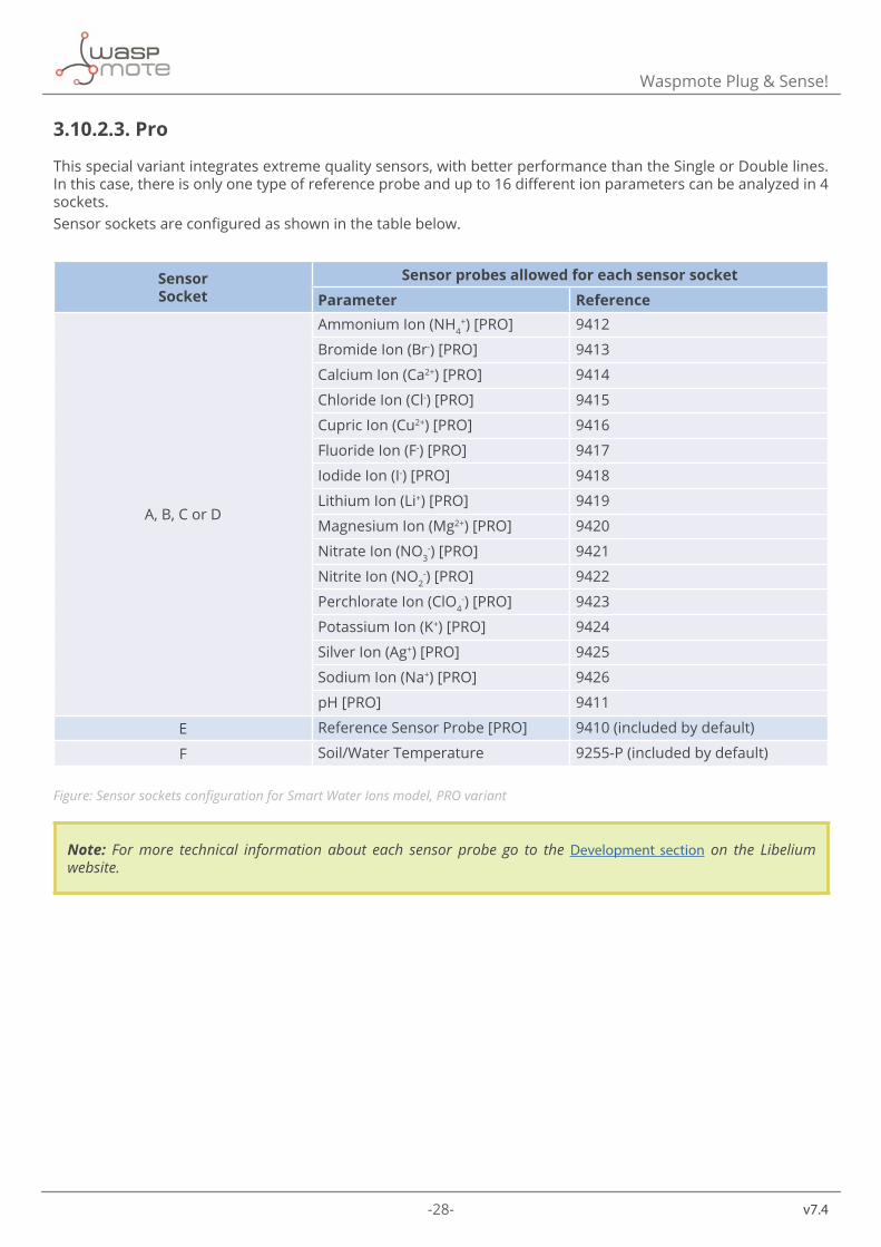
3.10.2.3. Pro
This special variant integrates extreme quality sensors, with better performance than the Single or Double lines. In this case, there is only one type of reference probe and up to 16 different ion parameters can be analyzed in 4 sockets. Sensor sockets are configured as shown in the table below.
SensorSocket
Sensor probes allowed for each sensor socketParameter Reference
A, B, C or D
Ammonium Ion (NH4+) [PRO] 9412
Bromide Ion (Br-) [PRO] 9413
Calcium Ion (Ca2+) [PRO] 9414
Chloride Ion (Cl-) [PRO] 9415
Cupric Ion (Cu2+) [PRO] 9416
Fluoride Ion (F-) [PRO] 9417
Iodide Ion (I-) [PRO] 9418
Lithium Ion (Li+) [PRO] 9419
Magnesium Ion (Mg2+) [PRO] 9420
Nitrate Ion (NO3-) [PRO] 9421
Nitrite Ion (NO2-) [PRO] 9422
Perchlorate Ion (ClO4-) [PRO] 9423
Potassium Ion (K+) [PRO] 9424
Silver Ion (Ag+) [PRO] 9425
Sodium Ion (Na+) [PRO] 9426
pH [PRO] 9411
E Reference Sensor Probe [PRO] 9410 (included by default)
F Soil/Water Temperature 9255-P (included by default)
Figure: Sensor sockets configuration for Smart Water Ions model, PRO variant
Note: For more technical information about each sensor probe go to the Development section on the Libelium website.
-29- v7.4
Waspmote Plug & Sense!
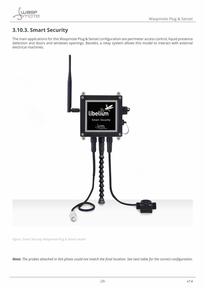
3.10.3. Smart SecurityThe main applications for this Waspmote Plug & Sense! configuration are perimeter access control, liquid presence detection and doors and windows openings. Besides, a relay system allows this model to interact with external electrical machines.
Figure: Smart Security Waspmote Plug & Sense! model
Note: The probes attached in this photo could not match the final location. See next table for the correct configuration.
-30-
v7.4
Waspmote Plug & Sense!
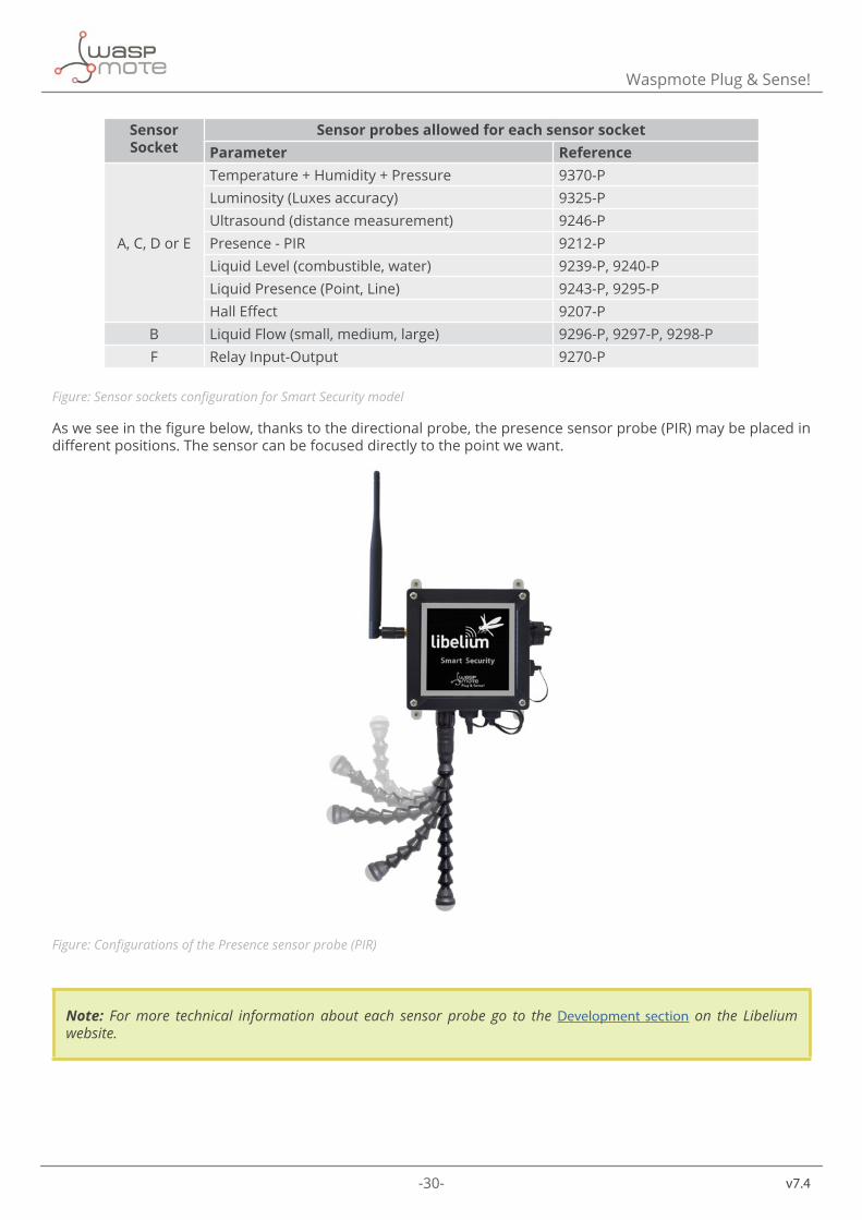
Sensor Socket
Sensor probes allowed for each sensor socketParameter Reference
A, C, D or E
Temperature + Humidity + Pressure 9370-PLuminosity (Luxes accuracy) 9325-PUltrasound (distance measurement) 9246-PPresence - PIR 9212-PLiquid Level (combustible, water) 9239-P, 9240-PLiquid Presence (Point, Line) 9243-P, 9295-PHall Effect 9207-P
B Liquid Flow (small, medium, large) 9296-P, 9297-P, 9298-PF Relay Input-Output 9270-P
Figure: Sensor sockets configuration for Smart Security model
As we see in the figure below, thanks to the directional probe, the presence sensor probe (PIR) may be placed in different positions. The sensor can be focused directly to the point we want.
Figure: Configurations of the Presence sensor probe (PIR)
Note: For more technical information about each sensor probe go to the Development section on the Libelium website.

-31- v7.4
Hardware
4. Hardware4.1. General descriptionThe Smart Water sensor board has been designed to facilitate the measurement of the most important chemical parameters that allow the remote monitoring of water quality in different scenarios, which includes contamination surveillance in natural environments such as rivers and lakes, control of the appropriate conditions of water in pools or fish farms and observation of industrial sewage from industries. Among these parameters are included water temperature, conductivity, pH, dissolved oxygen, oxidation-reduction potential (ORP) and turbidity.
4.2. SpecificationsWeight: 20 gDimensions: 73.5 x 51 x 1.3 mmTemperature range: [-20 ºC, 65 ºC]
Figure: Upper side
4.3. Electrical Characteristics • Board power voltages: 3.3 V and 5 V • Sensor power voltages: 3.3 V and 5 V • Maximum admitted current (continuous): 200 mA • Maximum admitted current (peak): 400 mA
-32-
v7.4
Sensors
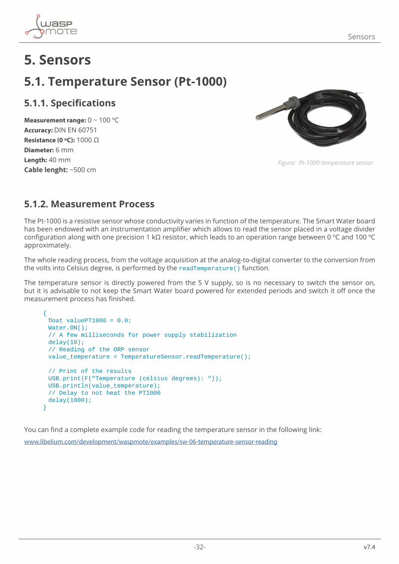
5. Sensors5.1. Temperature Sensor (Pt-1000)
5.1.1. Specifications
Measurement range: 0 ~ 100 ºCAccuracy: DIN EN 60751Resistance (0 ºC): 1000 ΩDiameter: 6 mmLength: 40 mmCable lenght: ~500 cm
5.1.2. Measurement Process
The Pt-1000 is a resistive sensor whose conductivity varies in function of the temperature. The Smart Water board has been endowed with an instrumentation amplifier which allows to read the sensor placed in a voltage divider configuration along with one precision 1 kΩ resistor, which leads to an operation range between 0 ºC and 100 ºC approximately.
The whole reading process, from the voltage acquisition at the analog-to-digital converter to the conversion from the volts into Celsius degree, is performed by the readTemperature() function.
The temperature sensor is directly powered from the 5 V supply, so is no necessary to switch the sensor on, but it is advisable to not keep the Smart Water board powered for extended periods and switch it off once the measurement process has finished.
{ floatvaluePT1000=0.0; Water.ON(); //Afewmillisecondsforpowersupplystabilization delay(10); //ReadingoftheORPsensor value_temperature=TemperatureSensor.readTemperature();
//Printoftheresults USB.print(F(“Temperature(celsiusdegrees):“)); USB.println(value_temperature); //DelaytonotheatthePT1000 delay(1000);}
You can find a complete example code for reading the temperature sensor in the following link:
www.libelium.com/development/waspmote/examples/sw-06-temperature-sensor-reading
Figure: Pt-1000 temperature sensor
-33- v7.4
Sensors
5.1.3. Socket
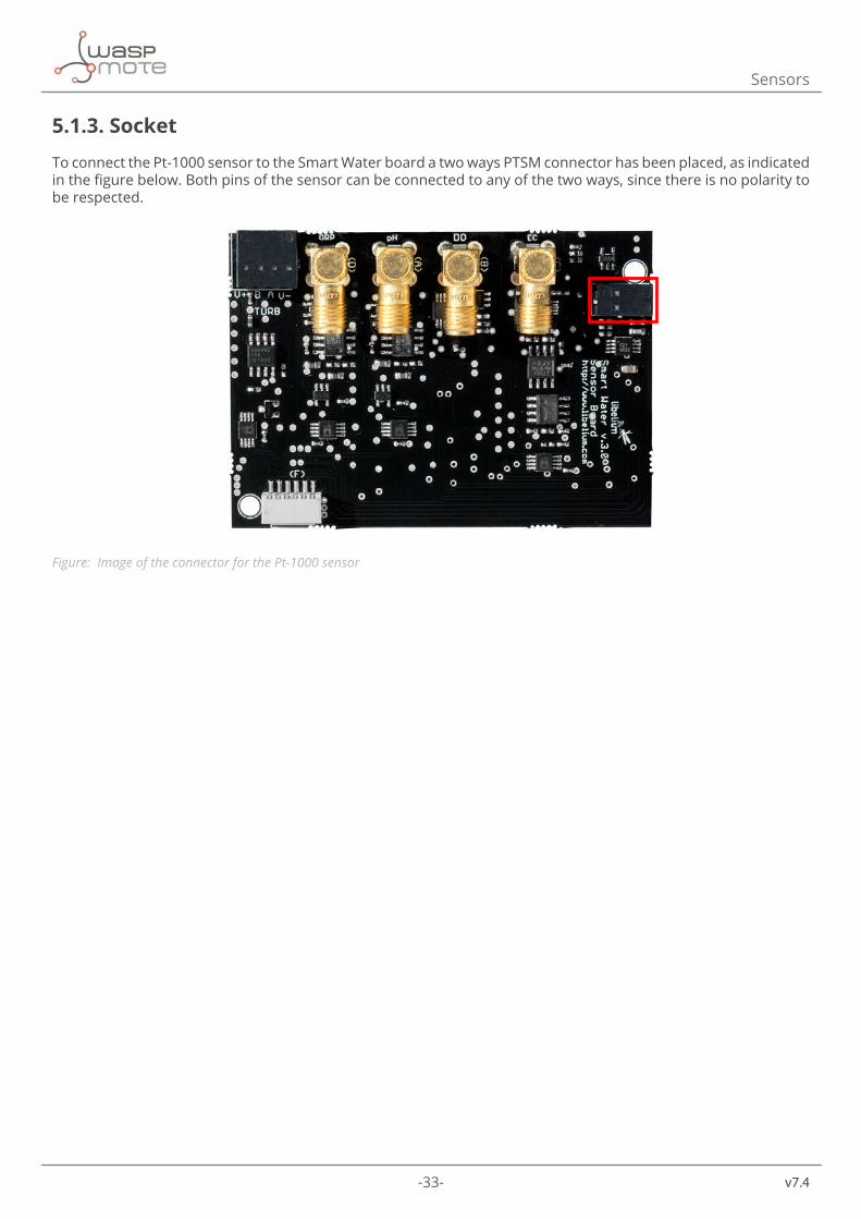
To connect the Pt-1000 sensor to the Smart Water board a two ways PTSM connector has been placed, as indicated in the figure below. Both pins of the sensor can be connected to any of the two ways, since there is no polarity to be respected.
Figure: Image of the connector for the Pt-1000 sensor
-34-
v7.4
Sensors
5.2. Conductivity sensor
5.2.1. Specifications
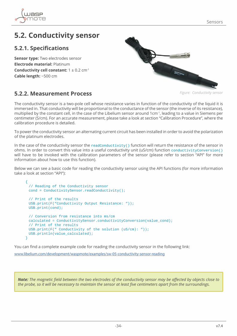
Sensor type: Two electrodes sensorElectrode material: PlatinumConductivity cell constant: 1 ± 0.2 cm-1
Cable length: ~500 cm
5.2.2. Measurement Process
The conductivity sensor is a two-pole cell whose resistance varies in function of the conductivity of the liquid it is immersed in. That conductivity will be proportional to the conductance of the sensor (the inverse of its resistance), multiplied by the constant cell, in the case of the Libelium sensor around 1cm-1, leading to a value in Siemens per centimeter (S/cm). For an accurate measurement, please take a look at section “Calibration Procedure”, where the calibration procedure is detailed.
To power the conductivity sensor an alternating current circuit has been installed in order to avoid the polarization of the platinum electrodes.
In the case of the conductivity sensor the readConductivity() function will return the resistance of the sensor in ohms. In order to convert this value into a useful conductivity unit (uS/cm) function conductivityConversion() will have to be invoked with the calibration parameters of the sensor (please refer to section “API” for more information about how to use this function).
Below we can see a basic code for reading the conductivity sensor using the API functions (for more information take a look at section “API”):
{ //ReadingoftheConductivitysensor cond=ConductivitySensor.readConductivity();
//Printoftheresults USB.print(F(“ConductivityOutputResistance:“)); USB.print(cond);
//Conversionfromresistanceintoms/cm calculated=ConductivitySensor.conductivityConversion(value_cond); //Printoftheresults USB.print(F(“Conductivityofthesolution(uS/cm):“)); USB.println(value_calculated);}
You can find a complete example code for reading the conductivity sensor in the following link:
www.libelium.com/development/waspmote/examples/sw-05-conductivity-sensor-reading
Note: The magnetic field between the two electrodes of the conductivity sensor may be affected by objects close to the probe, so it will be necessary to maintain the sensor at least five centimeters apart from the surroundings.
Figure: Conductivity sensor
-35- v7.4
Sensors
5.2.3. Socket
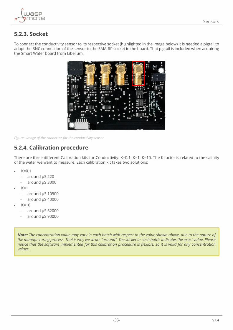
To connect the conductivity sensor to its respective socket (highlighted in the image below) it is needed a pigtail to adapt the BNC connection of the sensor to the SMA-RP socket in the board. That pigtail is included when acquiring the Smart Water board from Libelium.
Figure: Image of the connector for the conductivity sensor
5.2.4. Calibration procedure
There are three different Calibration kits for Conductivity: K=0.1, K=1; K=10. The K factor is related to the salinity of the water we want to measure. Each calibration kit takes two solutions:
• K=0.1 - around µS 220 - around µS 3000
• K=1 - around µS 10500 - around µS 40000
• K=10 - around µS 62000 - around µS 90000
Note: The concentration value may vary in each batch with respect to the value shown above, due to the nature of the manufacturing process. That is why we wrote “around”. The sticker in each bottle indicates the exact value. Please notice that the software implemented for this calibration procedure is flexible, so it is valid for any concentration values.
-36-
v7.4
Sensors
In the next table we see the typical conductivity depending on the kind of water we want to monitor:
Table of aqueous conductivitiesSolution µS/cm mS/cm ppmTotally pure water 0.055 - -Typical DI water 0.1 - -Distilled water 0.5 - -Domestic "tap" water 500-800 0.5-0.8 250-400Potable water (max) 1055 1.055 528Sea water 50,000 - 60,000 56 28,000
We see as the relation between conductivity and dissolved solids is approximately:2 µS/cm = 1 ppm (which is the same as 1 mg/l)
In order to get an accurate measurement it is recommended to calibrate the conductivity sensor to obtain a precise value of the cell constant. Although a single point calibration should be theoretically enough, a two point calibration is advisable to compensate for side effects of the circuitry, such as the resistance of the sensor wire or the connector. For a proper calibration two solutions of a conductivity as close as possible to that of the target environment should be used.
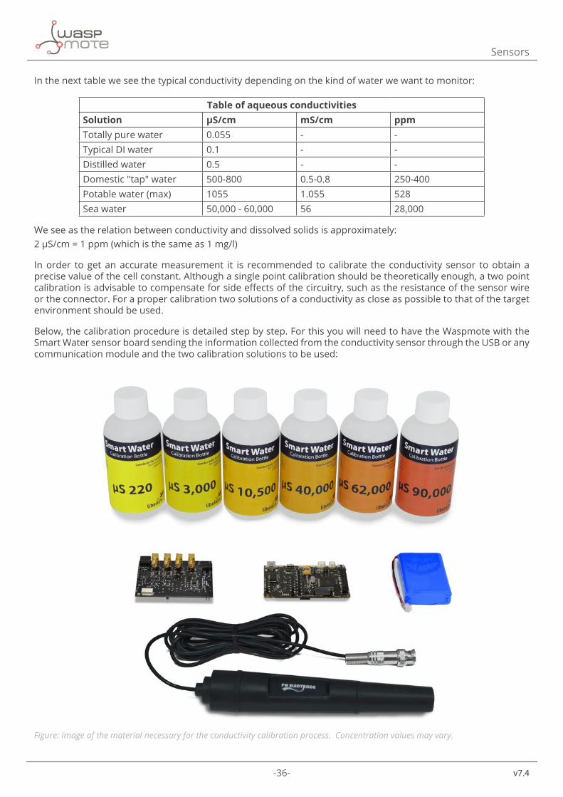
Below, the calibration procedure is detailed step by step. For this you will need to have the Waspmote with the Smart Water sensor board sending the information collected from the conductivity sensor through the USB or any communication module and the two calibration solutions to be used:
Figure: Image of the material necessary for the conductivity calibration process. Concentration values may vary.
-37- v7.4
Sensors
1. Turn on the Waspmote with the Smart Water sensor board and the conductivity sensor connected.
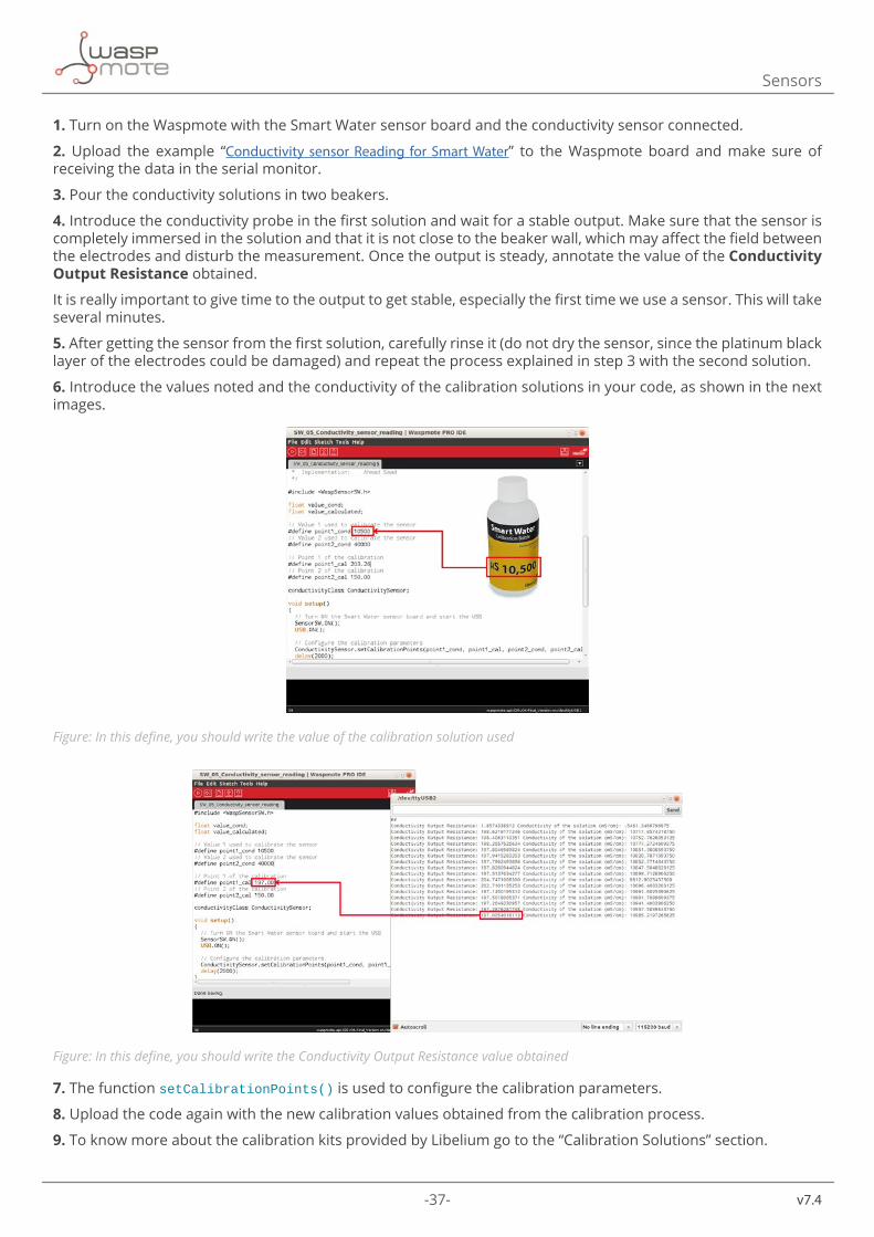
2. Upload the example “Conductivity sensor Reading for Smart Water” to the Waspmote board and make sure of receiving the data in the serial monitor.
3. Pour the conductivity solutions in two beakers.
4. Introduce the conductivity probe in the first solution and wait for a stable output. Make sure that the sensor is completely immersed in the solution and that it is not close to the beaker wall, which may affect the field between the electrodes and disturb the measurement. Once the output is steady, annotate the value of the Conductivity Output Resistance obtained.
It is really important to give time to the output to get stable, especially the first time we use a sensor. This will take several minutes.
5. After getting the sensor from the first solution, carefully rinse it (do not dry the sensor, since the platinum black layer of the electrodes could be damaged) and repeat the process explained in step 3 with the second solution.
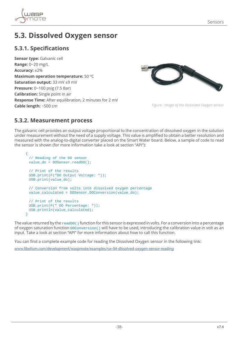
6. Introduce the values noted and the conductivity of the calibration solutions in your code, as shown in the next images.
Figure: In this define, you should write the value of the calibration solution used
Figure: In this define, you should write the Conductivity Output Resistance value obtained
7. The function setCalibrationPoints() is used to configure the calibration parameters.
8. Upload the code again with the new calibration values obtained from the calibration process.
9. To know more about the calibration kits provided by Libelium go to the “Calibration Solutions” section.
-38-
v7.4
Sensors
5.3. Dissolved Oxygen sensor
5.3.1. Specifications
Sensor type: Galvanic cellRange: 0~20 mg/LAccuracy: ±2%Maximum operation temperature: 50 ºCSaturation output: 33 mV ±9 mVPressure: 0~100 psig (7.5 Bar)Calibration: Single point in airResponse Time: After equilibration, 2 minutes for 2 mVCable length: ~500 cm
5.3.2. Measurement process
The galvanic cell provides an output voltage proportional to the concentration of dissolved oxygen in the solution under measurement without the need of a supply voltage. This value is amplified to obtain a better resolution and measured with the analog-to-digital converter placed on the Smart Water board. Below, a sample of code to read the sensor is shown (for more information take a look at section “API”):
{ //ReadingoftheDOsensor value_do=DOSensor.readDO();
//Printoftheresults USB.print(F(“DOOutputVoltage:“)); USB.print(value_do);
//Conversionfromvoltsintodissolvedoxygenpercentage value_calculated=DOSensor.DOConversion(value_do);
//Printoftheresults USB.print(F(“DOPercentage:“)); USB.println(value_calculated);}
The value returned by the readDO() function for this sensor is expressed in volts. For a conversion into a percentage of oxygen saturation function DOConversion() will have to be used, introducing the calibration value in volt as an input. Take a look at section “API” for more information about how to call this function.
You can find a complete example code for reading the Dissolved Oxygen sensor in the following link:
www.libelium.com/development/waspmote/examples/sw-04-dissolved-oxygen-sensor-reading
Figure: Image of the Dissolved Oxygen sensor
-39- v7.4
Sensors
5.3.3. Socket
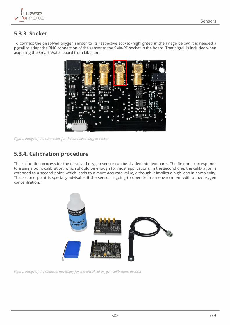
To connect the dissolved oxygen sensor to its respective socket (highlighted in the image below) it is needed a pigtail to adapt the BNC connection of the sensor to the SMA-RP socket in the board. That pigtail is included when acquiring the Smart Water board from Libelium.
Figure: Image of the connector for the dissolved oxygen sensor
5.3.4. Calibration procedure
The calibration process for the dissolved oxygen sensor can be divided into two parts. The first one corresponds to a single point calibration, which should be enough for most applications. In the second one, the calibration is extended to a second point, which leads to a more accurate value, although it implies a high leap in complexity. This second point is specially advisable if the sensor is going to operate in an environment with a low oxygen concentration.
Figure: Image of the material necessary for the dissolved oxygen calibration process
-40-
v7.4
Sensors
First point:
1. Turn on the Waspmote with the Smart Water sensor board and the dissolved oxygen sensor connected. Make sure the data from the sensor is being received properly.
2. Upload the code “Dissolved Oxygen Sensor Reading” and make sure the data from the sensor is being received properly in the serial monitor.
3. To get a saturated value of the sensor, just clean the sensor with distilled or de-ionized water, carefully rinse it and dry it with a paper cloth. Once in air, wait for the output stabilization. Once the measured value is steady, write it down. If the sensor has been deployed in a placement with difficult access, instead of getting it out it is possible to bubble air in the fluid until the sensor reaches saturation, though it is a less reliable method.
It is really important to give time to the output to get stable, especially the first time we use a sensor. This will take several minutes.
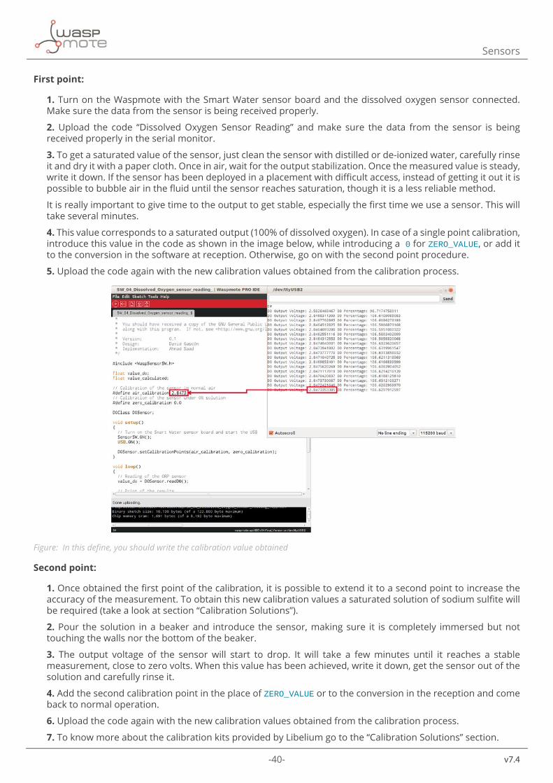
4. This value corresponds to a saturated output (100% of dissolved oxygen). In case of a single point calibration, introduce this value in the code as shown in the image below, while introducing a0 for ZERO_VALUE, or add it to the conversion in the software at reception. Otherwise, go on with the second point procedure.
5. Upload the code again with the new calibration values obtained from the calibration process.
Figure: In this define, you should write the calibration value obtained
Second point:
1. Once obtained the first point of the calibration, it is possible to extend it to a second point to increase the accuracy of the measurement. To obtain this new calibration values a saturated solution of sodium sulfite will be required (take a look at section “Calibration Solutions”).
2. Pour the solution in a beaker and introduce the sensor, making sure it is completely immersed but not touching the walls nor the bottom of the beaker.
3. The output voltage of the sensor will start to drop. It will take a few minutes until it reaches a stable measurement, close to zero volts. When this value has been achieved, write it down, get the sensor out of the solution and carefully rinse it.
4. Add the second calibration point in the place of ZERO_VALUE or to the conversion in the reception and come back to normal operation.
6. Upload the code again with the new calibration values obtained from the calibration process.
7. To know more about the calibration kits provided by Libelium go to the “Calibration Solutions” section.
-41- v7.4
Sensors
5.4. pH sensor
5.4.1. Specifications
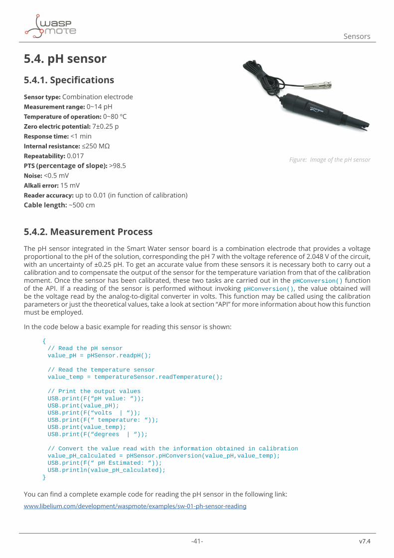
Sensor type: Combination electrode Measurement range: 0~14 pHTemperature of operation: 0~80 ºCZero electric potential: 7±0.25 pResponse time: <1 minInternal resistance: ≤250 MΩRepeatability: 0.017PTS (percentage of slope): >98.5Noise: <0.5 mVAlkali error: 15 mVReader accuracy: up to 0.01 (in function of calibration)Cable length: ~500 cm
5.4.2. Measurement Process
The pH sensor integrated in the Smart Water sensor board is a combination electrode that provides a voltage proportional to the pH of the solution, corresponding the pH 7 with the voltage reference of 2.048 V of the circuit, with an uncertainty of ±0.25 pH. To get an accurate value from these sensors it is necessary both to carry out a calibration and to compensate the output of the sensor for the temperature variation from that of the calibration moment. Once the sensor has been calibrated, these two tasks are carried out in the pHConversion() function of the API. If a reading of the sensor is performed without invoking pHConversion(), the value obtained will be the voltage read by the analog-to-digital converter in volts. This function may be called using the calibration parameters or just the theoretical values, take a look at section “API” for more information about how this function must be employed.
In the code below a basic example for reading this sensor is shown:
{ //ReadthepHsensor value_pH=pHSensor.readpH();
//Readthetemperaturesensor value_temp=temperatureSensor.readTemperature();
//Printtheoutputvalues USB.print(F(“pHvalue:“)); USB.print(value_pH); USB.print(F(“volts|“)); USB.print(F(“temperature:“)); USB.print(value_temp); USB.print(F(“degrees|“));
//Convertthevaluereadwiththeinformationobtainedincalibration value_pH_calculated=pHSensor.pHConversion(value_pH,value_temp); USB.print(F(“pHEstimated:“)); USB.println(value_pH_calculated);}
You can find a complete example code for reading the pH sensor in the following link:
www.libelium.com/development/waspmote/examples/sw-01-ph-sensor-reading
Figure: Image of the pH sensor
-42-
v7.4
Sensors
5.4.3. Socket
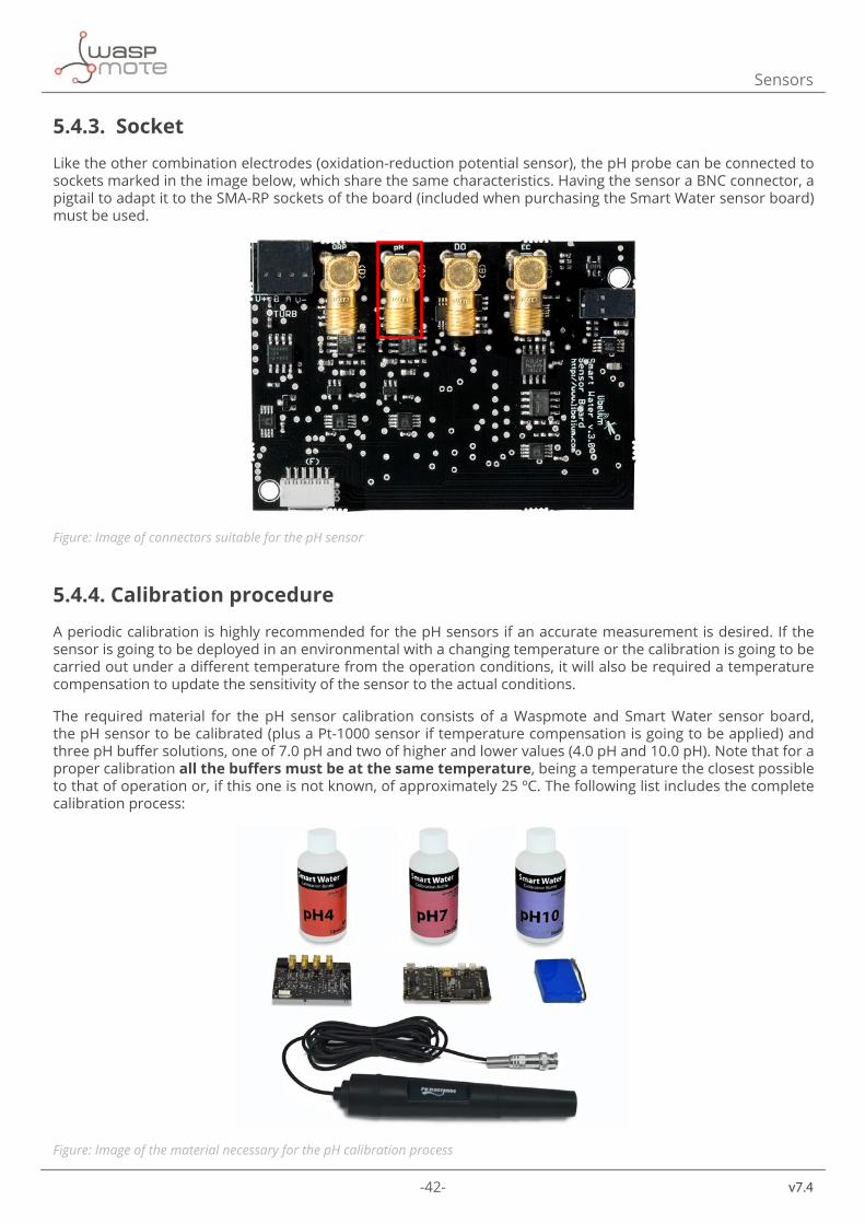
Like the other combination electrodes (oxidation-reduction potential sensor), the pH probe can be connected to sockets marked in the image below, which share the same characteristics. Having the sensor a BNC connector, a pigtail to adapt it to the SMA-RP sockets of the board (included when purchasing the Smart Water sensor board) must be used.
Figure: Image of connectors suitable for the pH sensor
5.4.4. Calibration procedure
A periodic calibration is highly recommended for the pH sensors if an accurate measurement is desired. If the sensor is going to be deployed in an environmental with a changing temperature or the calibration is going to be carried out under a different temperature from the operation conditions, it will also be required a temperature compensation to update the sensitivity of the sensor to the actual conditions.
The required material for the pH sensor calibration consists of a Waspmote and Smart Water sensor board, the pH sensor to be calibrated (plus a Pt-1000 sensor if temperature compensation is going to be applied) and three pH buffer solutions, one of 7.0 pH and two of higher and lower values (4.0 pH and 10.0 pH). Note that for a proper calibration all the buffers must be at the same temperature, being a temperature the closest possible to that of operation or, if this one is not known, of approximately 25 ºC. The following list includes the complete calibration process:
Figure: Image of the material necessary for the pH calibration process
-43- v7.4
Sensors
1. Turn on the Waspmote with the Smart Water sensor board and the pH sensor and the Pt-1000 connected.
2. Upload the code “pH Sensor Reading” and make sure the data is being correctly received through the USB or another communication module.
3. Pour the solutions in three beakers. The 4.0 pH solution is red, the 7.0 pH solution yellow and the 10.0 pH solution blue. It is recommended that the solutions are at the temperature that will be found at the installation environment.
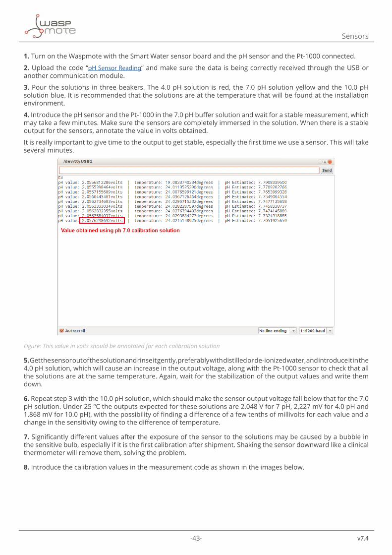
4. Introduce the pH sensor and the Pt-1000 in the 7.0 pH buffer solution and wait for a stable measurement, which may take a few minutes. Make sure the sensors are completely immersed in the solution. When there is a stable output for the sensors, annotate the value in volts obtained.
It is really important to give time to the output to get stable, especially the first time we use a sensor. This will take several minutes.
Figure: This value in volts should be annotated for each calibration solution
5. Get the sensor out of the solution and rinse it gently, preferably with distilled or de-ionized water, and introduce it in the 4.0 pH solution, which will cause an increase in the output voltage, along with the Pt-1000 sensor to check that all the solutions are at the same temperature. Again, wait for the stabilization of the output values and write them down.
6. Repeat step 3 with the 10.0 pH solution, which should make the sensor output voltage fall below that for the 7.0 pH solution. Under 25 ºC the outputs expected for these solutions are 2.048 V for 7 pH, 2,227 mV for 4.0 pH and 1.868 mV for 10.0 pH), with the possibility of finding a difference of a few tenths of millivolts for each value and a change in the sensitivity owing to the difference of temperature.
7. Significantly different values after the exposure of the sensor to the solutions may be caused by a bubble in the sensitive bulb, especially if it is the first calibration after shipment. Shaking the sensor downward like a clinical thermometer will remove them, solving the problem.
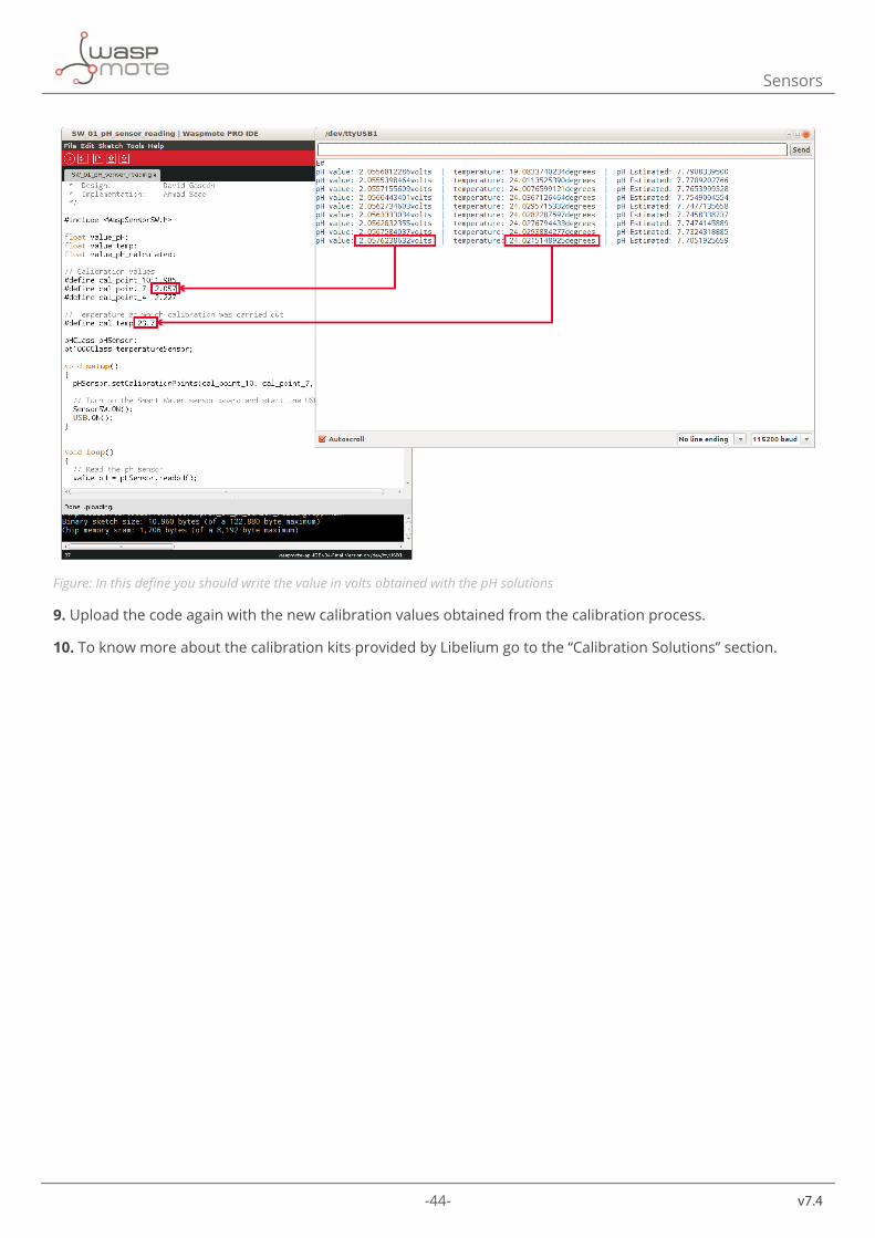
8. Introduce the calibration values in the measurement code as shown in the images below.
-44-
v7.4
Sensors
Figure: In this define you should write the value in volts obtained with the pH solutions
9. Upload the code again with the new calibration values obtained from the calibration process.
10. To know more about the calibration kits provided by Libelium go to the “Calibration Solutions” section.
-45- v7.4
Sensors
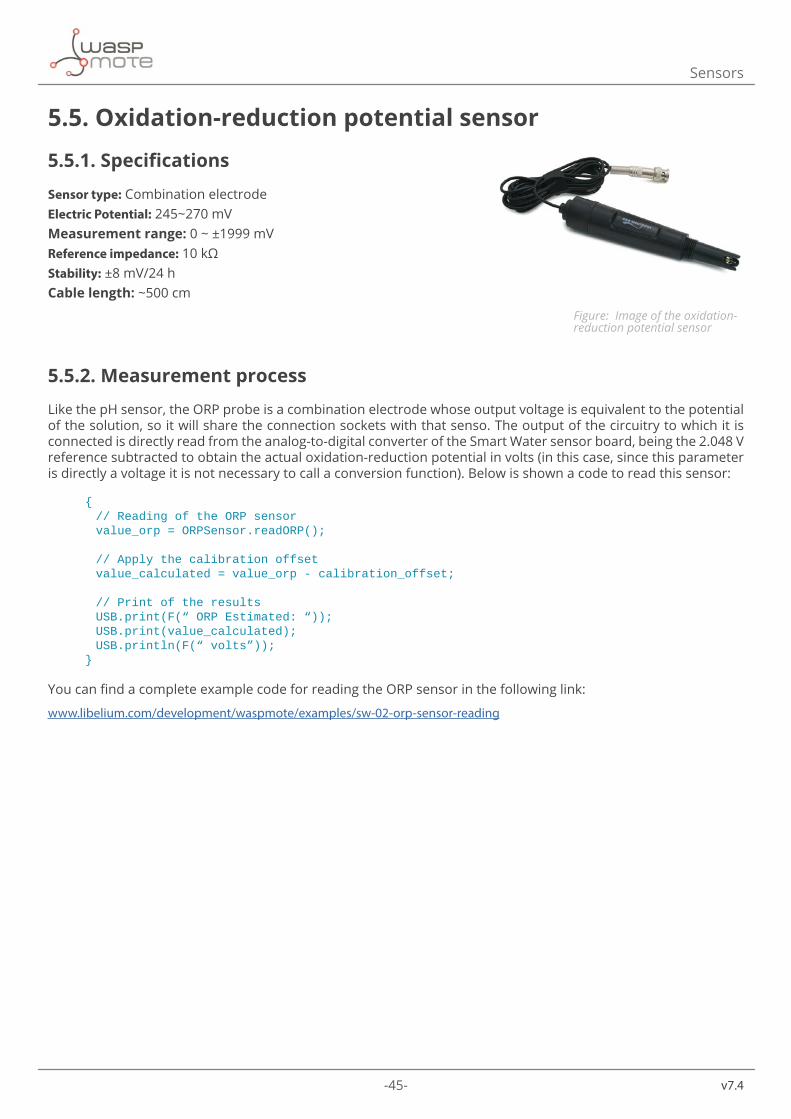
5.5. Oxidation-reduction potential sensor
5.5.1. Specifications
Sensor type: Combination electrode Electric Potential: 245~270 mVMeasurement range: 0 ~ ±1999 mVReference impedance: 10 kΩStability: ±8 mV/24 hCable length: ~500 cm
5.5.2. Measurement process
Like the pH sensor, the ORP probe is a combination electrode whose output voltage is equivalent to the potential of the solution, so it will share the connection sockets with that senso. The output of the circuitry to which it is connected is directly read from the analog-to-digital converter of the Smart Water sensor board, being the 2.048 V reference subtracted to obtain the actual oxidation-reduction potential in volts (in this case, since this parameter is directly a voltage it is not necessary to call a conversion function). Below is shown a code to read this sensor:
{ //ReadingoftheORPsensor value_orp=ORPSensor.readORP();
//Applythecalibrationoffset value_calculated=value_orp-calibration_offset;
//Printoftheresults USB.print(F(“ORPEstimated:“)); USB.print(value_calculated); USB.println(F(“volts”));}
You can find a complete example code for reading the ORP sensor in the following link:
www.libelium.com/development/waspmote/examples/sw-02-orp-sensor-reading
Figure: Image of the oxidation-reduction potential sensor
-46-
v7.4
Sensors
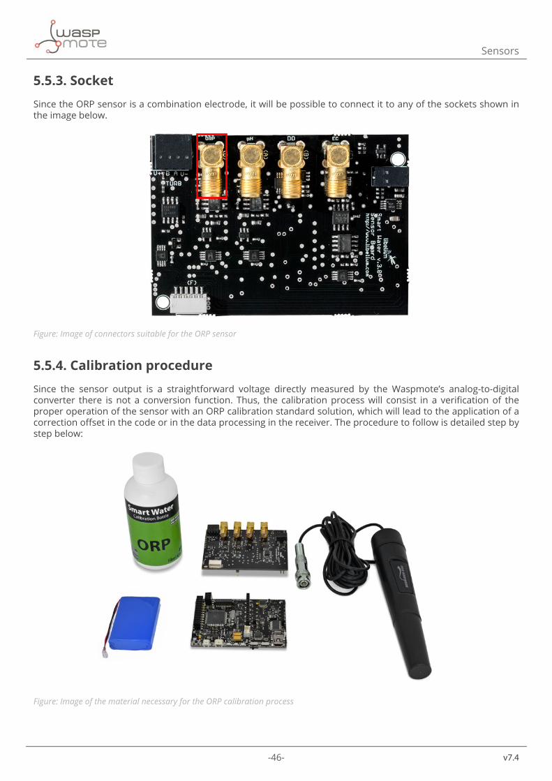
5.5.3. Socket
Since the ORP sensor is a combination electrode, it will be possible to connect it to any of the sockets shown in the image below.
Figure: Image of connectors suitable for the ORP sensor
5.5.4. Calibration procedure
Since the sensor output is a straightforward voltage directly measured by the Waspmote’s analog-to-digital converter there is not a conversion function. Thus, the calibration process will consist in a verification of the proper operation of the sensor with an ORP calibration standard solution, which will lead to the application of a correction offset in the code or in the data processing in the receiver. The procedure to follow is detailed step by step below:
Figure: Image of the material necessary for the ORP calibration process
-47- v7.4
Sensors
1. Turn on the Waspmote with the Smart Water sensor board and the ORP sensor connected.
2. Upload the code “ORP Sensor Reading” and make sure that the data from the sensor is being received through the USB or another communication module.
3. Pour the calibration solution in a beaker. Libelium provides a standard solution of 225 mV at 25 ºC.
4. Rinse the sensor with distilled or de-ionized water and softly dry it with filter paper.
5. Introduce the sensor into the calibration solution, making sure it stays completely immersed without contact with the beaker walls or bottom, and wait for the output value to stabilize. If the test is being carried out with the solution provided by Libelium at approximately 25 ºC, the output should be around the 225 mV, with a 10%~15% error.
6. It is really important to give time to the output to get stable, especially the first time we use a sensor. This will take several minutes.
7. A similar problem to the one mentioned for the pH sensor may appear owed to air bubbles in the sensitive bulb. If this is the case, shaking the sensor downward as stated for that sensor will also solve this problem.
8. Remove the sensor, rinse it with distilled or de-ionized water again and return it to its working place.
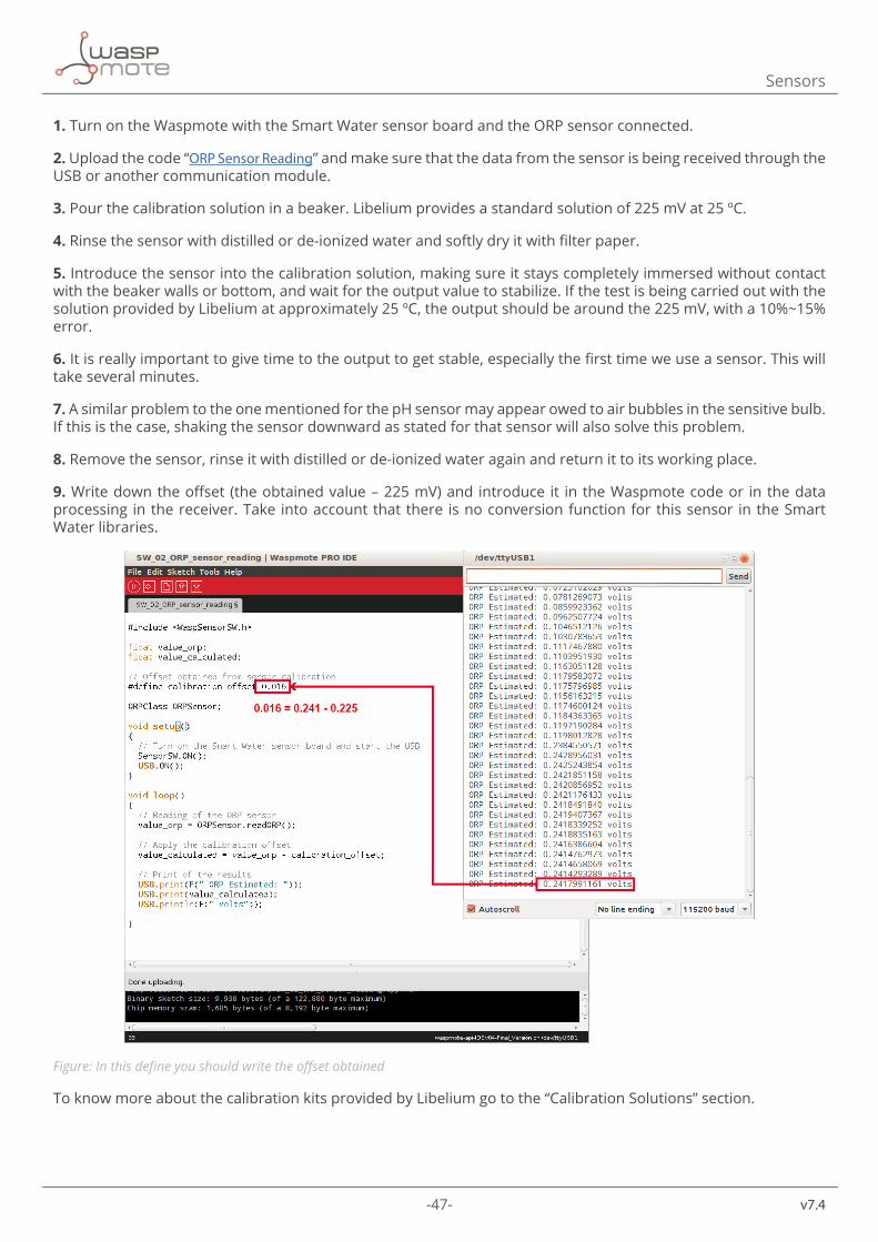
9. Write down the offset (the obtained value – 225 mV) and introduce it in the Waspmote code or in the data processing in the receiver. Take into account that there is no conversion function for this sensor in the Smart Water libraries.
Figure: In this define you should write the offset obtained
To know more about the calibration kits provided by Libelium go to the “Calibration Solutions” section.
-48-
v7.4
Sensors
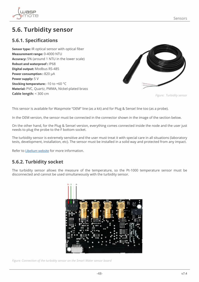
5.6. Turbidity sensor
5.6.1. Specifications
Sensor type: IR optical sensor with optical fiberMeasurement range: 0-4000 NTUAccuracy: 5% (around 1 NTU in the lower scale)Robust and waterproof : IP68Digital output: Modbus RS-485Power consumption : 820 μAPower supply: 5 VStocking temperature: -10 to +60 °CMaterial: PVC, Quartz, PMMA, Nickel-plated brassCable length: < 300 cm
This sensor is available for Waspmote “OEM” line (as a kit) and for Plug & Sense! line too (as a probe).
In the OEM version, the sensor must be connected in the connector shown in the image of the section below.
On the other hand, for the Plug & Sense! version, everything comes connected inside the node and the user just needs to plug the probe to the F bottom socket.
The turbidity sensor is extremely sensitive and the user must treat it with special care in all situations (laboratory tests, development, installation, etc). The sensor must be installed in a solid way and protected from any impact.
Refer to Libelium website for more information.
5.6.2. Turbidity socket
The turbidity sensor allows the measure of the temperature, so the Pt-1000 temperature sensor must be disconnected and cannot be used simultaneously with the turbidity sensor.
Figure: Connection of the turbidity sensor on the Smart Water sensor board
Figure: Turbidity sensor
-49- v7.4
Sensors
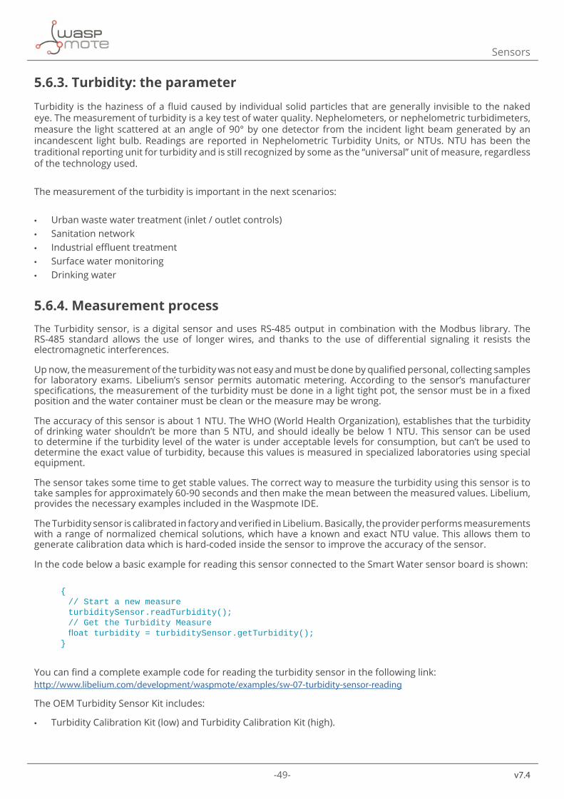
5.6.3. Turbidity: the parameter
Turbidity is the haziness of a fluid caused by individual solid particles that are generally invisible to the naked eye. The measurement of turbidity is a key test of water quality. Nephelometers, or nephelometric turbidimeters, measure the light scattered at an angle of 90° by one detector from the incident light beam generated by an incandescent light bulb. Readings are reported in Nephelometric Turbidity Units, or NTUs. NTU has been the traditional reporting unit for turbidity and is still recognized by some as the “universal” unit of measure, regardless of the technology used.
The measurement of the turbidity is important in the next scenarios:
• Urban waste water treatment (inlet / outlet controls) • Sanitation network • Industrial effluent treatment • Surface water monitoring • Drinking water
5.6.4. Measurement processThe Turbidity sensor, is a digital sensor and uses RS-485 output in combination with the Modbus library. The RS-485 standard allows the use of longer wires, and thanks to the use of differential signaling it resists the electromagnetic interferences.
Up now, the measurement of the turbidity was not easy and must be done by qualified personal, collecting samples for laboratory exams. Libelium’s sensor permits automatic metering. According to the sensor’s manufacturer specifications, the measurement of the turbidity must be done in a light tight pot, the sensor must be in a fixed position and the water container must be clean or the measure may be wrong.
The accuracy of this sensor is about 1 NTU. The WHO (World Health Organization), establishes that the turbidity of drinking water shouldn’t be more than 5 NTU, and should ideally be below 1 NTU. This sensor can be used to determine if the turbidity level of the water is under acceptable levels for consumption, but can’t be used to determine the exact value of turbidity, because this values is measured in specialized laboratories using special equipment.
The sensor takes some time to get stable values. The correct way to measure the turbidity using this sensor is to take samples for approximately 60-90 seconds and then make the mean between the measured values. Libelium, provides the necessary examples included in the Waspmote IDE.
The Turbidity sensor is calibrated in factory and verified in Libelium. Basically, the provider performs measurements with a range of normalized chemical solutions, which have a known and exact NTU value. This allows them to generate calibration data which is hard-coded inside the sensor to improve the accuracy of the sensor.
In the code below a basic example for reading this sensor connected to the Smart Water sensor board is shown:
{ //Startanewmeasure turbiditySensor.readTurbidity(); //GettheTurbidityMeasure floatturbidity=turbiditySensor.getTurbidity();}
You can find a complete example code for reading the turbidity sensor in the following link:http://www.libelium.com/development/waspmote/examples/sw-07-turbidity-sensor-reading
The OEM Turbidity Sensor Kit includes:
• Turbidity Calibration Kit (low) and Turbidity Calibration Kit (high).
-50-
v7.4
Sensors
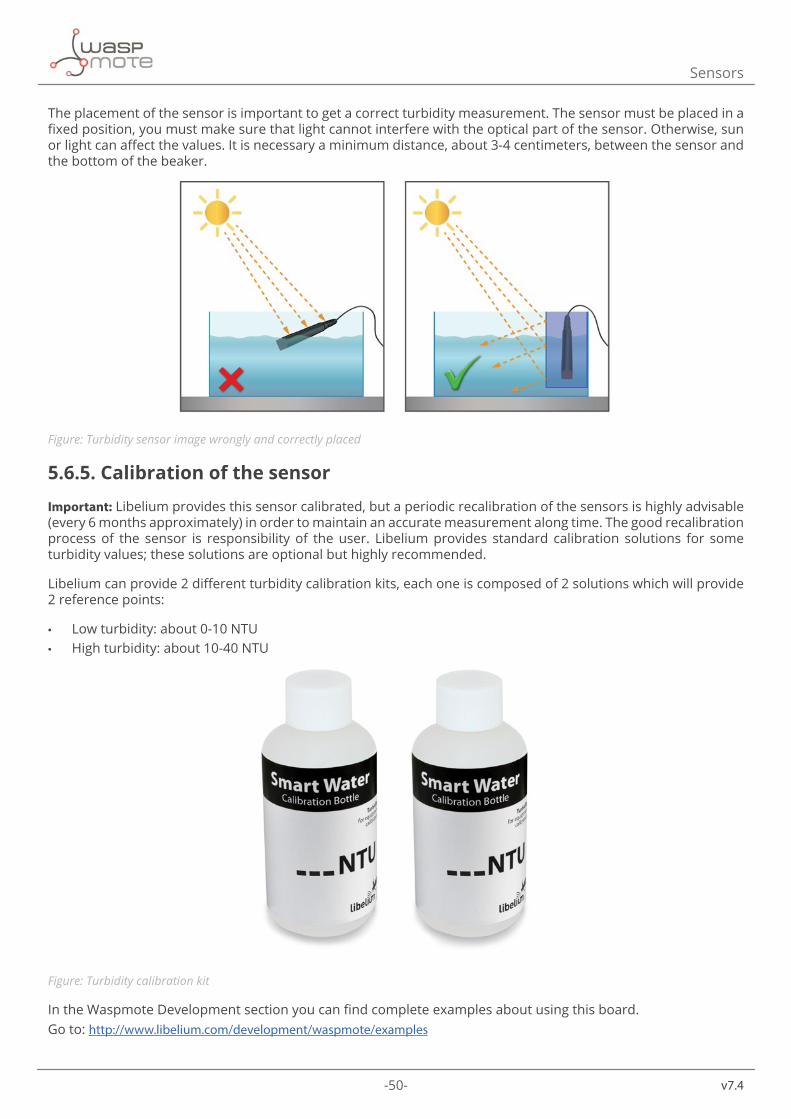
The placement of the sensor is important to get a correct turbidity measurement. The sensor must be placed in a fixed position, you must make sure that light cannot interfere with the optical part of the sensor. Otherwise, sun or light can affect the values. It is necessary a minimum distance, about 3-4 centimeters, between the sensor and the bottom of the beaker.
Figure: Turbidity sensor image wrongly and correctly placed
5.6.5. Calibration of the sensor
Important: Libelium provides this sensor calibrated, but a periodic recalibration of the sensors is highly advisable (every 6 months approximately) in order to maintain an accurate measurement along time. The good recalibration process of the sensor is responsibility of the user. Libelium provides standard calibration solutions for some turbidity values; these solutions are optional but highly recommended.
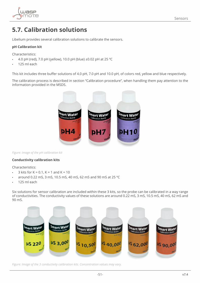
Libelium can provide 2 different turbidity calibration kits, each one is composed of 2 solutions which will provide 2 reference points:
• Low turbidity: about 0-10 NTU • High turbidity: about 10-40 NTU
Figure: Turbidity calibration kit
In the Waspmote Development section you can find complete examples about using this board. Go to: http://www.libelium.com/development/waspmote/examples
-51- v7.4
Sensors
5.7. Calibration solutionsLibelium provides several calibration solutions to calibrate the sensors.
pH Calibration kit
Characteristics: • 4.0 pH (red), 7.0 pH (yellow), 10.0 pH (blue) ±0.02 pH at 25 ºC • 125 ml each
This kit includes three buffer solutions of 4.0 pH, 7.0 pH and 10.0 pH, of colors red, yellow and blue respectively.
The calibration process is described in section “Calibration procedure”, when handling them pay attention to the information provided in the MSDS.
Figure: Image of the pH calibration kit
Conductivity calibration kits
Characteristics: • 3 kits for K = 0.1, K = 1 and K = 10 • around 0.22 mS, 3 mS, 10.5 mS, 40 mS, 62 mS and 90 mS at 25 ºC • 125 ml each
Six solutions for sensor calibration are included within these 3 kits, so the probe can be calibrated in a way range of conductivities. The conductivity values of these solutions are around 0.22 mS, 3 mS, 10.5 mS, 40 mS, 62 mS and 90 mS.
Figure: Image of the 3 conductivity calibration kits. Concentration values may vary.
-52-
v7.4
Sensors
ORP Calibration solution
Characteristics:
• 225 mV ±2 mV at 25 ºC • 100 ml each
The ORP calibration solution provides a 225mV output at 25ºC (beware that it may change at different temperatures) which facilitates the adjustment of the sensor output to the actual values of oxidation-reduction potential. Note that this buffer will keep its properties for 30 days once open. It is recommended to store refrigerated.
Figure: Image of the ORP calibration solution
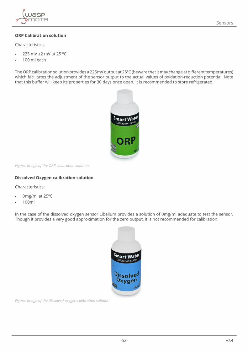
Dissolved Oxygen calibration solution
Characteristics:
• 0mg/ml at 25ºC • 100ml
In the case of the dissolved oxygen sensor Libelium provides a solution of 0mg/ml adequate to test the sensor. Though it provides a very good approximation for the zero output, it is not recommended for calibration.
Figure: Image of the dissolved oxygen calibration solution
-53- v7.4
Sensors
Note: remember to read carefully the material safety data sheets you can findin the “Safety guides” section of this guide, in order to take the corresponding precautions when manipulating these solutions and dispose them in the appropriate way.
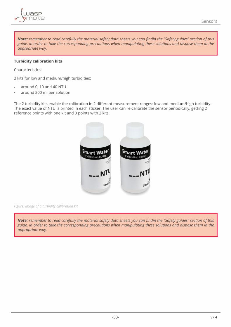
Turbidity calibration kits
Characteristics:
2 kits for low and medium/high turbidities:
• around 0, 10 and 40 NTU • around 200 ml per solution
The 2 turbidity kits enable the calibration in 2 different measurement ranges: low and medium/high turbidity. The exact value of NTU is printed in each sticker. The user can re-calibrate the sensor periodically, getting 2 reference points with one kit and 3 points with 2 kits.
Figure: Image of a turbidity calibration kit
Note: remember to read carefully the material safety data sheets you can findin the “Safety guides” section of this guide, in order to take the corresponding precautions when manipulating these solutions and dispose them in the appropriate way.
-54-
v7.4
Sensors
5.8. General considerations about probes performance and life expectancyWhen developing a new application with the Smart Water sensor board the conditions of the environment the sensors are going to operate in will deeply affect the durability and behavior of the probes. Thus, it is highly recommended to carry out an exhaustive study of the characteristics of the location of the device and perform all the laboratory tests required in order to assure the correct election of the sensors and of the way they will be deployed. Libelium provides standard sensors which have been largely tested and will work in most of the environments, but keep always in mind that if they are subjected to harmful chemicals present in certain specific scenarios they may be irreversibly damaged. Below a few tips regarding the setup of the sensors are listed:
Sensor deployment
The main problems regarding the setup of the sensors concern both the way and the place they are deployed in.
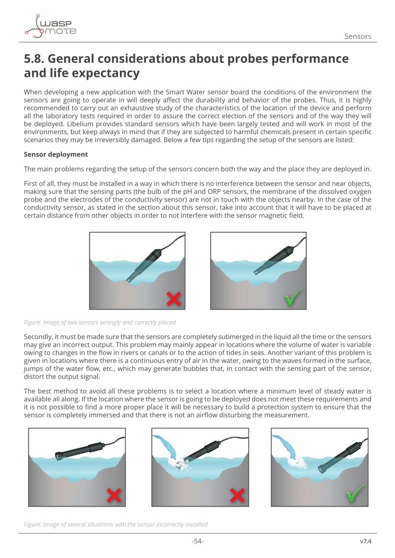
First of all, they must be installed in a way in which there is no interference between the sensor and near objects, making sure that the sensing parts (the bulb of the pH and ORP sensors, the membrane of the dissolved oxygen probe and the electrodes of the conductivity sensor) are not in touch with the objects nearby. In the case of the conductivity sensor, as stated in the section about this sensor, take into account that it will have to be placed at certain distance from other objects in order to not interfere with the sensor magnetic field.
Figure: Image of two sensors wrongly and correctly placed
Secondly, it must be made sure that the sensors are completely submerged in the liquid all the time or the sensors may give an incorrect output. This problem may mainly appear in locations where the volume of water is variable owing to changes in the flow in rivers or canals or to the action of tides in seas. Another variant of this problem is given in locations where there is a continuous entry of air in the water, owing to the waves formed in the surface, jumps of the water flow, etc., which may generate bubbles that, in contact with the sensing part of the sensor, distort the output signal.
The best method to avoid all these problems is to select a location where a minimum level of steady water is available all along. If the location where the sensor is going to be deployed does not meet these requirements and it is not possible to find a more proper place it will be necessary to build a protection system to ensure that the sensor is completely immersed and that there is not an airflow disturbing the measurement.
Figure: Image of several situations with the sensor incorrectly installed
-55- v7.4
Sensors
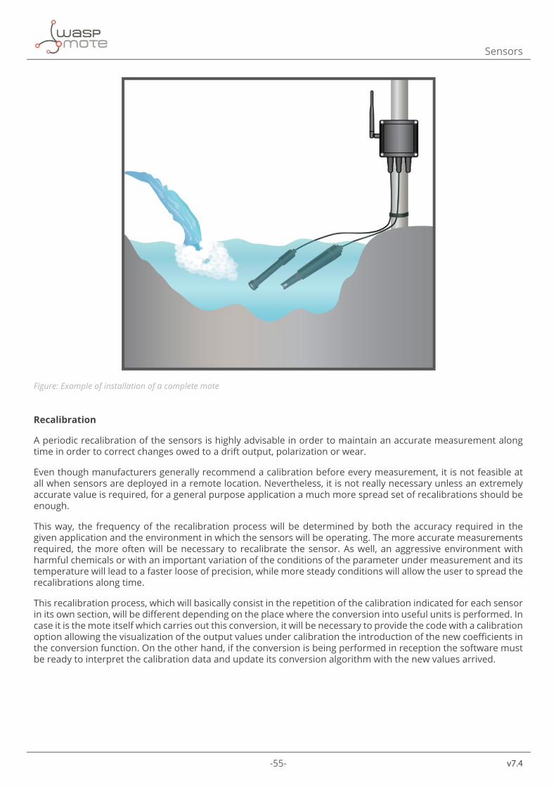
Figure: Example of installation of a complete mote
Recalibration
A periodic recalibration of the sensors is highly advisable in order to maintain an accurate measurement along time in order to correct changes owed to a drift output, polarization or wear.
Even though manufacturers generally recommend a calibration before every measurement, it is not feasible at all when sensors are deployed in a remote location. Nevertheless, it is not really necessary unless an extremely accurate value is required, for a general purpose application a much more spread set of recalibrations should be enough.
This way, the frequency of the recalibration process will be determined by both the accuracy required in the given application and the environment in which the sensors will be operating. The more accurate measurements required, the more often will be necessary to recalibrate the sensor. As well, an aggressive environment with harmful chemicals or with an important variation of the conditions of the parameter under measurement and its temperature will lead to a faster loose of precision, while more steady conditions will allow the user to spread the recalibrations along time.
This recalibration process, which will basically consist in the repetition of the calibration indicated for each sensor in its own section, will be different depending on the place where the conversion into useful units is performed. In case it is the mote itself which carries out this conversion, it will be necessary to provide the code with a calibration option allowing the visualization of the output values under calibration the introduction of the new coefficients in the conversion function. On the other hand, if the conversion is being performed in reception the software must be ready to interpret the calibration data and update its conversion algorithm with the new values arrived.
-56-
v7.4
Sensors
Life expectancy
If they are not subject to harassing environments Smart Water sensors may keep on functioning for periods of several months, providing the required recalibrations are performed to maintain the accuracy demanded by the application. Tests carried out at Libelium facilities have shown that sensors working for at least six months have not suffered an important variance in their output and still provide an accurate output when calibrated.
However, the chemical processes given in the sensor measurement will finally end up the sensor life. In the case of the pH, ORP and dissolved oxygen the depletion of the solution of both the reference and measurement electrodes and the wear of the sensitive bulb or membrane are the principal reasons for sensor failure. In the case of the conductivity sensor, the polarization of the electrodes (attenuated by the application of an alternating supply current but not completely avoided), the accumulation of dirt in them and the wear of the platinum black layer are the most significant sources of damage.
We can summarize that both recalibration and lifetime of the sensor probes depend on three main factors:
• 1- Water environment: corrosive chemicals, salt, dirt, extreme temperatures, strong flow currents decrease the lifetime.
• 2- Usage: the more the probes are used the sooner they need to be changed due to the depletion of the substances used as reference and measurement electrodes.
• 3- Time: event in perfect conditions and low usage the chemical reactions that take place in the reference electrodes will stop working.
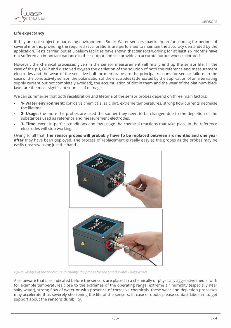
Owing to all that, the sensor probes will probably have to be replaced between six months and one year after they have been deployed. The process of replacement is really easy as the probes as the probes may be easily unscrew using just the hand.
Figure: Images of the procedure to change the probes for the Smart Water Plug&Sense!
Also beware that if as indicated before the sensors are placed in a chemically or physically aggressive media, with for example temperatures close to the extremes of the operating range, extreme air humidity (especially near salty water), strong flow of water or with presence of corrosive chemicals, these wear and depletion processes may accelerate thus severely shortening the life of the sensors. In case of doubt please contact Libelium to get support about the sensors’ durability.
-57- v7.4
Sensors
How to detect that the probes are not working properly
There are certain symptoms that will reveal that a sensor is not working properly:
• A lack of a proper response during calibration process. This is an obvious error which may appear in different ways and in different degree. A noisy output of several millivolts when submerging the probes in the calibration solutions, inconsistent values with the expected output given in section “Calibration Procedure” and never reaching a stable output will be indicatives of a defective of probe.
• A steady continuous measurement for a long time. It is very rare that these sensors show a continuous value in a real environment as they do in laboratory. Owing to liquid flow, temperature effects or biological action, a slow fluctuation is to be expected. If the measurement is stalled in a given value, the probe will probably be broken.
• A sudden change in the output of the sensor. The sensors’ reaction is not instantaneous, if there is a leap between two consecutive measurements a problem with the sensor may have occurred (this kind of error may not be detected if a long time takes place between measurements).
• Values out of range. If the sensor drifts out of the normal operation range it will probably be caused by a failure.
If there are doubts about the correct operation of the sensor it is recommended to carry out a new calibration in order to discard any possible malfunction.
Important summary:
• Due to the chemical nature of the sensors, the user must recalibrate them periodically. The frequency of this recalibration process depends on the accuracy desired and on the environment conditions; this time should be concluded after real tests. A standard recalibration period would be one month, but certain applications may force to recalibrate after a few days.
• The lifetime of the sensors depends on many factors. The standard expectancy is about one year but harsh environment conditions could be decreased it to some months.
-58-
v7.4
Board configuration and programming
6. Board configuration and programming6.1. Hardware configurationThe Smart Water sensor board does not require any other manipulation than the sensor connection to its corresponding socket. There are two kind of connectors on the Smart Water board:
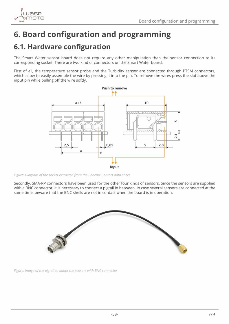
First of all, the temperature sensor probe and the Turbidity sensor are connected through PTSM connectors, which allow to easily assemble the wire by pressing it into the pin. To remove the wires press the slot above the input pin while pulling off the wire softly.
Figure: Diagram of the socket extracted from the Phoenix Contact data sheet
Secondly, SMA-RP connectors have been used for the other four kinds of sensors. Since the sensors are supplied with a BNC connector, it is necessary to connect a pigtail in between. In case several sensors are connected at the same time, beware that the BNC shells are not in contact when the board is in operation.
Figure: Image of the pigtail to adapt the sensors with BNC connector
-59- v7.4
Board configuration and programming
6.2. LibraryAll the software functions necessary to operate the Smart Water sensor board have been compiled in a library added to the Waspmote API, so the supply of the board and its components and the reading of the sensors can be easily managed.
When using the Smart Water sensor board, remember it is mandatory to include the SensorSW library by introducing the next line at the beginning of the code:
#include<WaspSensorSW.h>
Next, the different functions that make up the library are described:
Power control functions
Turns on the sensor board by activating the 3.3 V and 5 V supply voltage lines from Waspmote:Water.ON()
Turns off the sensor board by cutting the 3.3 V and 5 V supply voltage lines from Waspmote:Water.OFF()
Read sensor functions
Returns the temperature value from Pt-1000:floatreadTemperature(void)
Returns the pH value:floatreadpH(void)
Returns the value of the oxidation-reduction potential:floatreadORP(void)
Returns the value of the dissolved oxygen:floatreadDO(void)
Returns the value of the conductivity:floatreadConductivity(void)
Conversion functions
Converts from volts to pH value with no temperature compensation: floatpHConversion(floatinput)
Converts from volts to pH value with temperature compensation:floatpHConversion(floatinput,floattemp)

-60-
v7.4
Board configuration and programming
Converts from resistance to conductivity (ms/cm):
floatconductivityConversion(floatinput)Converts the DO voltage into a percentage of concentration:
floatDOConversion(floatinput)
Calibration configuration functions
Configures the calibration points of the pH sensor:
setCalibrationPoints(float_cal_point_10,float_cal_point_7, float_cal_point_4,float_cal_temperature)
Configure the calibration points of the conductivity sensor:
setCalibrationPoints(float_point_1_cond, float_point_1_cal, float_point_2_cond, float_point_2_cal)
Configure the calibration points of the DO sensor:
setCalibrationPoints(float_air_calibration,float_zero_calibration)
The files related to this sensor board are: WaspSensorSW.cpp, WaspSensorSW.h
They can be downloaded from:
http://www.libelium.com/development/waspmote/sdk_and_applications
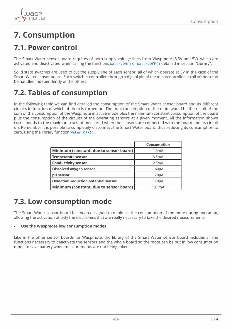
-61- v7.4
Consumption
7. Consumption7.1. Power controlThe Smart Water sensor board requires of both supply voltage lines from Waspmote (3.3V and 5V), which are activated and deactivated when calling the functions Water.ON() or Water.OFF() detailed in section “Library”.
Solid state switches are used to cut the supply line of each sensor, all of which operate at 5V in the case of the Smart Water sensor board. Each switch is controlled through a digital pin of the microcontroller, so all of them can be handled independently of the others.
7.2. Tables of consumptionIn the following table we can find detailed the consumption of the Smart Water sensor board and its different circuits in function of which of them is turned on. The total consumption of the mote would be the result of the sum of the consumption of the Waspmote in active mode plus the minimum constant consumption of the board plus the consumption of the circuits of the operating sensors at a given moment. All the information shown corresponds to the maximum current measured when the sensors are connected with the board and its circuit on. Remember it is possible to completely disconnect the Smart Water board, thus reducing its consumption to zero, using the library function Water.OFF().
Consumption
Minimum (constant, due to sensor board) 1.6mA
Temperature sensor 3.5mA
Conductivity sensor 2.5mA
Dissolved oxygen sensor 160μA
pH sensor 170μA
Oxidation-reduction potential sensor 170μA
Minimum (constant, due to sensor board) 1.0 mA
7.3. Low consumption modeThe Smart Water sensor board has been designed to minimize the consumption of the mote during operation, allowing the activation of only the electronics that are really necessary to take the desired measurements.
• Use the Waspmote low consumption modes
Like in the other sensor boards for Waspmote, the library of the Smart Water sensor board includes all the functions necessary to deactivate the sensors and the whole board so the mote can be put in low consumption mode to save battery when measurements are not being taken.

-62-
v7.4
Safety guides
8. Safety guides8.1. pH 4.00 Calibration SolutionSection 1: Product and Company Identification • Product name: pH 4.00 Calibration Solution • Synonyms/General Names: pH 4.00 Buffer solution • Product Use: For device calibration
#US/Canada/International: 24 Hour Emergency Information Telephone NumbersCHEMTREC (USA): 800.424.9300CANUTEC (Canada): 613.424.6666International 703-527-3887
#Spain: Centro Nacional de ToxicologíaTeléfono: 91 5620420http://institutodetoxicologia.justicia.es/
Section 2: Hazards IdentificationRed liquid; no odor.CAUTION! Body tissue irritant.Target organs: None known.This material is not considered hazardous by the OSHA Hazard Communication Standard (29 CFR 1910.1200) if used properly.
Section 3: Composition / Information on Ingredients • Potassium Hydrogen Phthalate: 10.21g, 1-2% • Hydrochloric Acid: 1ml, <1% • Water: (7732-18-5), 97-99% • Food coloring: <1%
Section 4: First Aid MeasuresAlways seek professional medical attention after first aid measures are provided.
• Eyes: Immediately flush eyes with excess water for 15 minutes, lifting lower and upper eyelids occasionally. • Skin: Immediately flush skin with excess water for 15 minutes while removing contaminated clothing. • Ingestion: Call Poison Control immediately. Rinse mouth with cold water. Give victim 1-2 cups of water or milk
to drink. Induce vomiting immediately. • Inhalation: Remove to fresh air. If not breathing, give artificial respiration.
Section 5: Fire Fighting MeasuresNon-combustible solution. When heated to decomposition, emits acrid fumes.
Protective equipment and precautions for firefighters: Use foam or dry chemical to extinguish fire.
Firefighters should wear full fire fighting turn-out gear and respiratory protection (SCBA). Cool container with water spray. Material is not sensitive to mechanical impact or static discharge.
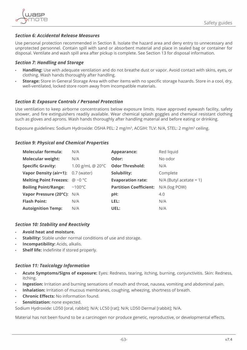
-63- v7.4
Safety guides
Section 6: Accidental Release MeasuresUse personal protection recommended in Section 8. Isolate the hazard area and deny entry to unnecessary and unprotected personnel. Contain spill with sand or absorbent material and place in sealed bag or container for disposal. Ventilate and wash spill area after pickup is complete. See Section 13 for disposal information.
Section 7: Handling and Storage • Handling: Use with adequate ventilation and do not breathe dust or vapor. Avoid contact with skins, eyes, or
clothing. Wash hands thoroughly after handling. • Storage: Store in General Storage Area with other items with no specific storage hazards. Store in a cool, dry,
well-ventilated, locked store room away from incompatible materials.
Section 8: Exposure Controls / Personal ProtectionUse ventilation to keep airborne concentrations below exposure limits. Have approved eyewash facility, safety shower, and fire extinguishers readily available. Wear chemical splash goggles and chemical resistant clothing such as gloves and aprons. Wash hands thoroughly after handling material and before eating or drinking.
Exposure guidelines: Sodium Hydroxide: OSHA PEL: 2 mg/m3, ACGIH: TLV: N/A, STEL: 2 mg/m3 ceiling.
Section 9: Physical and Chemical Properties
Molecular formula: N/A Appearance: Red liquid
Molecular weight: N/A Odor: No odor
Specific Gravity: 1.00 g/mL @ 20°C Odor Threshold: N/A
Vapor Density (air=1): 0.7 (water) Solubility: Complete
Melting Point Freezes: @ ~0 °C Evaporation rate: N/A (Butyl acetate = 1)
Boiling Point/Range: ~100°C Partition Coefficient: N/A (log POW)
Vapor Pressure (20°C): N/A pH: 4.0
Flash Point: N/A LEL: N/A
Autoignition Temp: N/A UEL: N/A
Section 10: Stability and Reactivity • Avoid heat and moisture. • Stability: Stable under normal conditions of use and storage. • Incompatibility: Acids, alkalis. • Shelf life: Indefinite if stored properly.
Section 11: Toxicology Information • Acute Symptoms/Signs of exposure: Eyes: Redness, tearing, itching, burning, conjunctivitis. Skin: Redness,
itching. • Ingestion: Irritation and burning sensations of mouth and throat, nausea, vomiting and abdominal pain. • Inhalation: Irritation of mucous membranes, coughing, wheezing, shortness of breath. • Chronic Effects: No information found. • Sensitization: none expected.
Sodium Hydroxide: LD50 [oral, rabbit]; N/A; LC50 [rat]; N/A; LD50 Dermal [rabbit]; N/A.
Material has not been found to be a carcinogen nor produce genetic, reproductive, or developmental effects.
-64-
v7.4
Safety guides
Section 12: Ecological Information • Ecotoxicity (aquatic and terrestrial): Not considered an environmental hazard.
Section 13: Disposal ConsiderationsCheck with all applicable local, regional, and national laws and regulations. Local regulations may be more stringent than regional or national regulations. Small amounts of this material may be suitable for sanitary sewer or trash disposal.
Section 14: Transport Information • DOT Shipping Name: Not regulated by DOT • DOT Hazard Class: • Identification Number: • Canada TDG: Not regulated by TDG • Hazard Class: • UN Number:
Section 15: Regulatory Information • EINECS: Not listed • TSCA: All components are listed or are exempt • WHMIS Canada: Not WHMIS Controlled • California Proposition 65: Not listed
The product has been classified in accordance with the hazard criteria of the Controlled Products Regulations and the MSDS contains all the information required by the Controlled Products Regulations.
Section 16: Other Information • Current Issue Date: January 2011
Disclaimer: Libelium believes that the information herein is factual but is not intended to be all inclusive. The information relates only to the specific material designated and does not relate to its use in combination with other materials or its use as to any particular process. Because safety standards and regulations are subject to change and because Libelium has no continuing control over the material, those handling, storing or using the material should satisfy themselves that they have current information regarding the particular way the material is handled, stored or used and that the same is done in accordance with federal, state and local law. Libelium makes no warranty, expressed or implied, including (without limitation) warranties with respect to the completeness or continuing accuracy of the information contained herein or with respect to fitness for any particular use.
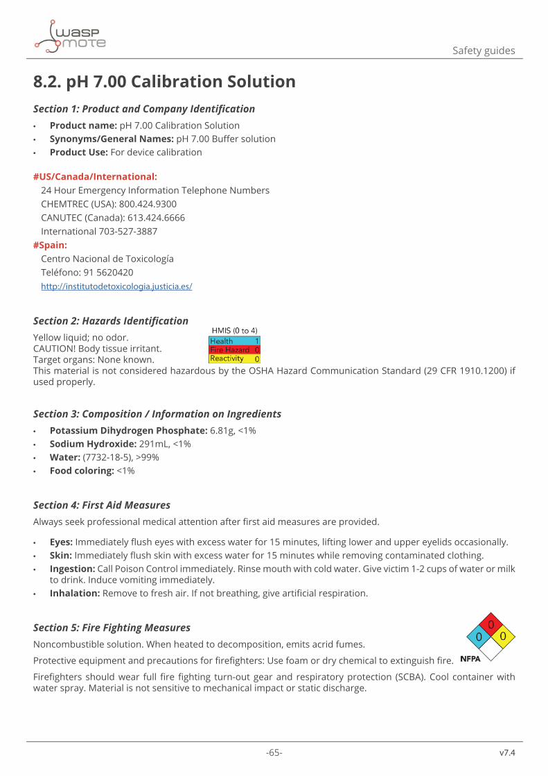
-65- v7.4
Safety guides
8.2. pH 7.00 Calibration Solution Section 1: Product and Company Identification • Product name: pH 7.00 Calibration Solution • Synonyms/General Names: pH 7.00 Buffer solution • Product Use: For device calibration
#US/Canada/International: 24 Hour Emergency Information Telephone NumbersCHEMTREC (USA): 800.424.9300CANUTEC (Canada): 613.424.6666International 703-527-3887
#Spain: Centro Nacional de ToxicologíaTeléfono: 91 5620420http://institutodetoxicologia.justicia.es/
Section 2: Hazards IdentificationYellow liquid; no odor.CAUTION! Body tissue irritant.Target organs: None known.This material is not considered hazardous by the OSHA Hazard Communication Standard (29 CFR 1910.1200) if used properly.
Section 3: Composition / Information on Ingredients • Potassium Dihydrogen Phosphate: 6.81g, <1% • Sodium Hydroxide: 291mL, <1% • Water: (7732-18-5), >99% • Food coloring: <1%
Section 4: First Aid MeasuresAlways seek professional medical attention after first aid measures are provided.
• Eyes: Immediately flush eyes with excess water for 15 minutes, lifting lower and upper eyelids occasionally. • Skin: Immediately flush skin with excess water for 15 minutes while removing contaminated clothing. • Ingestion: Call Poison Control immediately. Rinse mouth with cold water. Give victim 1-2 cups of water or milk
to drink. Induce vomiting immediately. • Inhalation: Remove to fresh air. If not breathing, give artificial respiration.
Section 5: Fire Fighting MeasuresNoncombustible solution. When heated to decomposition, emits acrid fumes.
Protective equipment and precautions for firefighters: Use foam or dry chemical to extinguish fire.
Firefighters should wear full fire fighting turn-out gear and respiratory protection (SCBA). Cool container with water spray. Material is not sensitive to mechanical impact or static discharge.
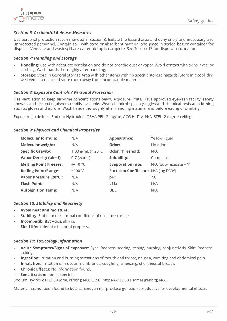
-66-
v7.4
Safety guides
Section 6: Accidental Release MeasuresUse personal protection recommended in Section 8. Isolate the hazard area and deny entry to unnecessary and unprotected personnel. Contain spill with sand or absorbent material and place in sealed bag or container for disposal. Ventilate and wash spill area after pickup is complete. See Section 13 for disposal information.
Section 7: Handling and Storage • Handling: Use with adequate ventilation and do not breathe dust or vapor. Avoid contact with skins, eyes, or
clothing. Wash hands thoroughly after handling. • Storage: Store in General Storage Area with other items with no specific storage hazards. Store in a cool, dry,
well-ventilated, locked store room away from incompatible materials.
Section 8: Exposure Controls / Personal ProtectionUse ventilation to keep airborne concentrations below exposure limits. Have approved eyewash facility, safety shower, and fire extinguishers readily available. Wear chemical splash goggles and chemical resistant clothing such as gloves and aprons. Wash hands thoroughly after handling material and before eating or drinking.
Exposure guidelines: Sodium Hydroxide: OSHA PEL: 2 mg/m3, ACGIH: TLV: N/A, STEL: 2 mg/m3 ceiling.
Section 9: Physical and Chemical Properties
Molecular formula: N/A Appearance: Yellow liquid
Molecular weight: N/A Odor: No odor
Specific Gravity: 1.00 g/mL @ 20°C Odor Threshold: N/A
Vapor Density (air=1): 0.7 (water) Solubility: Complete
Melting Point Freezes: @ ~0 °C Evaporation rate: N/A (Butyl acetate = 1)
Boiling Point/Range: ~100°C Partition Coefficient: N/A (log POW)
Vapor Pressure (20°C): N/A pH: 7.0
Flash Point: N/A LEL: N/A
Autoignition Temp: N/A UEL: N/A
Section 10: Stability and Reactivity • Avoid heat and moisture. • Stability: Stable under normal conditions of use and storage. • Incompatibility: Acids, alkalis. • Shelf life: Indefinite if stored properly.
Section 11: Toxicology Information • Acute Symptoms/Signs of exposure: Eyes: Redness, tearing, itching, burning, conjunctivitis. Skin: Redness,
itching. • Ingestion: Irritation and burning sensations of mouth and throat, nausea, vomiting and abdominal pain. • Inhalation: Irritation of mucous membranes, coughing, wheezing, shortness of breath. • Chronic Effects: No information found. • Sensitization: none expected.
Sodium Hydroxide: LD50 [oral, rabbit]; N/A; LC50 [rat]; N/A; LD50 Dermal [rabbit]; N/A.
Material has not been found to be a carcinogen nor produce genetic, reproductive, or developmental effects.
-67- v7.4
Safety guides
Section 12: Ecological Information • Ecotoxicity (aquatic and terrestrial): Not considered an environmental hazard.
Section 13: Disposal Considerations
Check with all applicable local, regional, and national laws and regulations. Local regulations may be more stringent than regional or national regulations. Small amounts of this material may be suitable for sanitary sewer or trash disposal.
Section 14: Transport Information • DOT Shipping Name: Not regulated by DOT • DOT Hazard Class: • Identification Number: • Canada TDG: Not regulated by TDG • Hazard Class: • UN Number:
Section 15: Regulatory Information • EINECS: Not listed. • TSCA: All components are listed or are exempt. • WHMIS Canada: Not WHMIS Controlled. • California Proposition 65: Not listed.
The product has been classified in accordance with the hazard criteria of the Controlled Products Regulations and the MSDS contains all the information required by the Controlled Products Regulations.
Section 16: Other Information • Current Issue Date: January 2011
Disclaimer: Libelium believes that the information herein is factual but is not intended to be all inclusive. The information relates only to the specific material designated and does not relate to its use in combination with other materials or its use as to any particular process. Because safety standards and regulations are subject to change and because Libelium has no continuing control over the material, those handling, storing or using the material should satisfy themselves that they have current information regarding the particular way the material is handled, stored or used and that the same is done in accordance with federal, state and local law. Libelium makes no warranty, expressed or implied, including (without limitation) warranties with respect to the completeness or continuing accuracy of the information contained herein or with respect to fitness for any particular use.
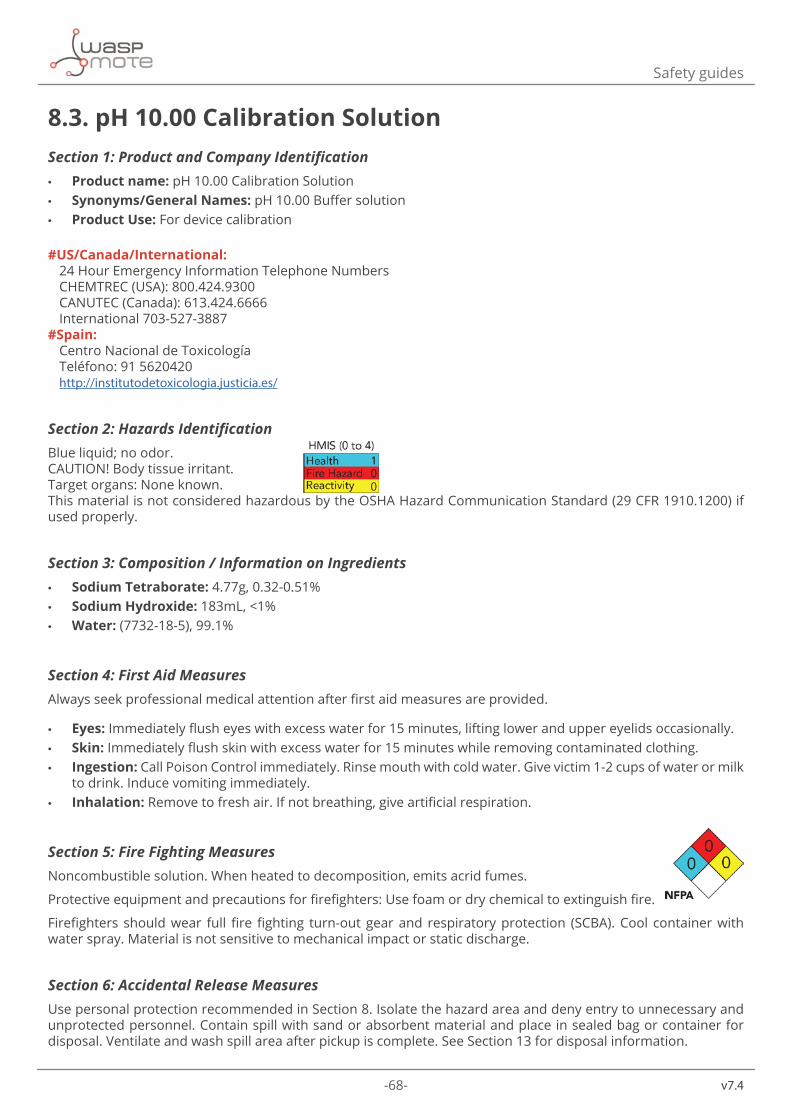
-68-
v7.4
Safety guides
8.3. pH 10.00 Calibration Solution Section 1: Product and Company Identification • Product name: pH 10.00 Calibration Solution • Synonyms/General Names: pH 10.00 Buffer solution • Product Use: For device calibration
#US/Canada/International:
24 Hour Emergency Information Telephone NumbersCHEMTREC (USA): 800.424.9300CANUTEC (Canada): 613.424.6666International 703-527-3887
#Spain: Centro Nacional de ToxicologíaTeléfono: 91 5620420http://institutodetoxicologia.justicia.es/
Section 2: Hazards IdentificationBlue liquid; no odor.CAUTION! Body tissue irritant.Target organs: None known.This material is not considered hazardous by the OSHA Hazard Communication Standard (29 CFR 1910.1200) if used properly.
Section 3: Composition / Information on Ingredients • Sodium Tetraborate: 4.77g, 0.32-0.51% • Sodium Hydroxide: 183mL, <1% • Water: (7732-18-5), 99.1%
Section 4: First Aid MeasuresAlways seek professional medical attention after first aid measures are provided.
• Eyes: Immediately flush eyes with excess water for 15 minutes, lifting lower and upper eyelids occasionally. • Skin: Immediately flush skin with excess water for 15 minutes while removing contaminated clothing. • Ingestion: Call Poison Control immediately. Rinse mouth with cold water. Give victim 1-2 cups of water or milk
to drink. Induce vomiting immediately. • Inhalation: Remove to fresh air. If not breathing, give artificial respiration.
Section 5: Fire Fighting MeasuresNoncombustible solution. When heated to decomposition, emits acrid fumes.
Protective equipment and precautions for firefighters: Use foam or dry chemical to extinguish fire.
Firefighters should wear full fire fighting turn-out gear and respiratory protection (SCBA). Cool container with water spray. Material is not sensitive to mechanical impact or static discharge.
Section 6: Accidental Release MeasuresUse personal protection recommended in Section 8. Isolate the hazard area and deny entry to unnecessary and unprotected personnel. Contain spill with sand or absorbent material and place in sealed bag or container for disposal. Ventilate and wash spill area after pickup is complete. See Section 13 for disposal information.
-69- v7.4
Safety guides
Section 7: Handling and Storage • Handling: Use with adequate ventilation and do not breathe dust or vapor. Avoid contact with skins, eyes, or
clothing. Wash hands thoroughly after handling. • Storage: Store in General Storage Area with other items with no specific storage hazards. Store in a cool, dry,
well-ventilated, locked store room away from incompatible materials.
Section 8: Exposure Controls / Personal ProtectionUse ventilation to keep airborne concentrations below exposure limits. Have approved eyewash facility, safety shower, and fire extinguishers readily available. Wear chemical splash goggles and chemical resistant clothing such as gloves and aprons. Wash hands thoroughly after handling material and before eating or drinking. Use NIOSH-approved respirator with an dust cartridge.
Exposure guidelines: Sodium hydroxide: OSHA PEL: Not Available, ACGIH: TLV: Not Available, STEL: Not Available.
Section 9: Physical and Chemical Properties
Molecular formula: N/A Appearance: Blue liquid
Molecular weight: N/A Odor: No odor
Specific Gravity: 1.00 g/mL @ 20°C Odor Threshold: N/A
Vapor Density (air=1): 0.7 (water) Solubility: Complete
Melting Point Freezes: @ ~0 °C Evaporation rate: N/A (Butyl acetate = 1)
Boiling Point/Range: ~100°C Partition Coefficient: N/A (log POW)
Vapor Pressure (20°C): N/A pH: 10.0
Flash Point: N/A LEL: N/A
Autoignition Temp: N/A UEL: N/A
Section 10: Stability and Reactivity • Avoid heat and moisture. • Stability: Stable under normal conditions of use and storage. • Incompatibility: Acids, alkalis. • Shelf life: Indefinite if stored properly.
Section 11: Toxicology Information • Acute Symptoms/Signs of exposure: Eyes: Redness, tearing, itching, burning, conjunctivitis. Skin: Redness,
itching. • Ingestion: Irritation and burning sensations of mouth and throat, nausea, vomiting and abdominal pain. • Inhalation: Irritation of mucous membranes, coughing, wheezing, shortness of breath. • Chronic Effects: No information found. • Sensitization: none expected.
Sodium Hydroxide: LD50 [oral, rabbit]; N/A; LC50 [rat]; N/A; LD50 Dermal [rabbit]; N/A.
Material has not been found to be a carcinogen nor produce genetic, reproductive, or developmental effects.
Section 12: Ecological Information • Ecotoxicity (aquatic and terrestrial): Not considered an environmental hazard.
-70-
v7.4
Safety guides
Section 13: Disposal ConsiderationsCheck with all applicable local, regional, and national laws and regulations. Local regulations may be more stringent than regional or national regulations. Small amounts of this material may be suitable for sanitary sewer or trash disposal.
Section 14: Transport Information • DOT Shipping Name: Not regulated by DOT • DOT Hazard Class: • Identification Number: • Canada TDG: Not regulated by TDG • Hazard Class: • UN Number:
Section 15: Regulatory Information • EINECS: Not listed. • TSCA: All components are listed or are exempt. • WHMIS Canada: Not WHMIS Controlled. • California Proposition 65: Not listed.
The product has been classified in accordance with the hazard criteria of the Controlled Products Regulations and the MSDS contains all the information required by the Controlled Products Regulations.
Section 16: Other Information • Current Issue Date: January 2011
Disclaimer: Libelium believes that the information herein is factual but is not intended to be all inclusive. The information relates only to the specific material designated and does not relate to its use in combination with other materials or its use as to any particular process. Because safety standards and regulations are subject to change and because Libelium has no continuing control over the material, those handling, storing or using the material should satisfy themselves that they have current information regarding the particular way the material is handled, stored or used and that the same is done in accordance with federal, state and local law. Libelium makes no warranty, expressed or implied, including (without limitation) warranties with respect to the completeness or continuing accuracy of the information contained herein or with respect to fitness for any particular use.
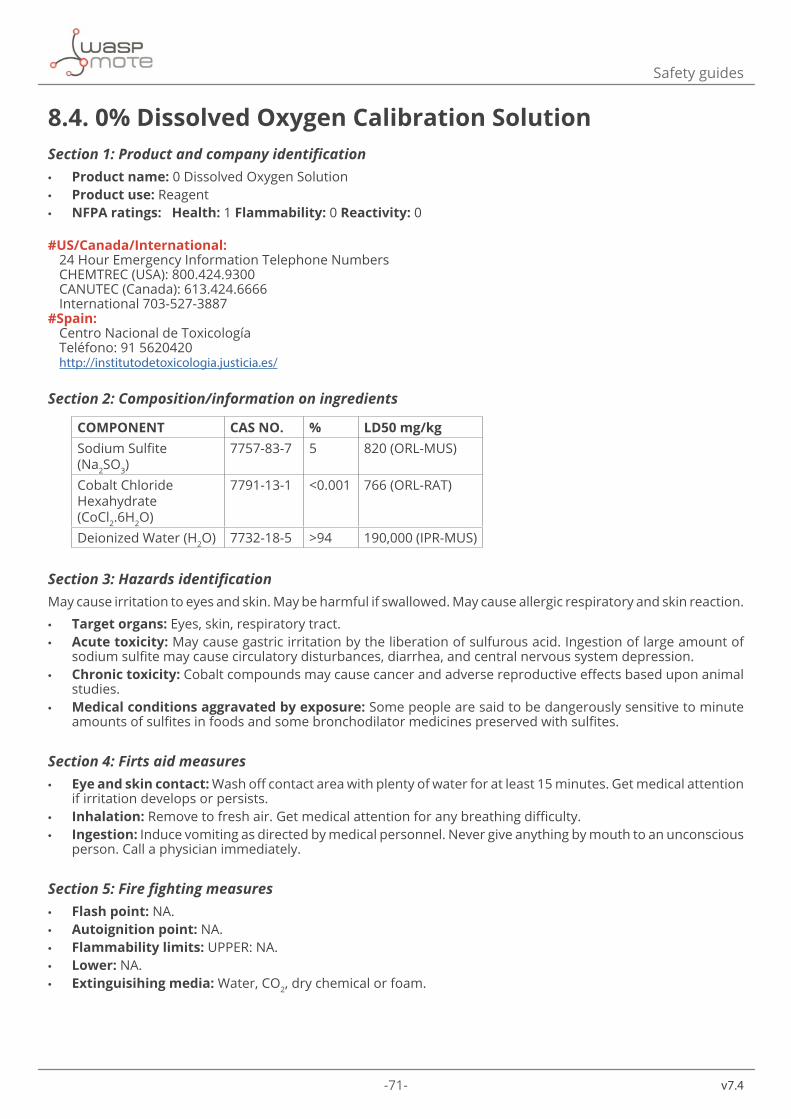
-71- v7.4
Safety guides
8.4. 0% Dissolved Oxygen Calibration SolutionSection 1: Product and company identification • Product name: 0 Dissolved Oxygen Solution • Product use: Reagent • NFPA ratings: Health: 1 Flammability: 0 Reactivity: 0
#US/Canada/International: 24 Hour Emergency Information Telephone NumbersCHEMTREC (USA): 800.424.9300CANUTEC (Canada): 613.424.6666International 703-527-3887
#Spain: Centro Nacional de ToxicologíaTeléfono: 91 5620420http://institutodetoxicologia.justicia.es/
Section 2: Composition/information on ingredients
COMPONENT CAS NO. % LD50 mg/kgSodium Sulfite (Na2SO3)
7757-83-7 5 820 (ORL-MUS)
Cobalt Chloride Hexahydrate (CoCl2.6H2O)
7791-13-1 <0.001 766 (ORL-RAT)
Deionized Water (H2O) 7732-18-5 >94 190,000 (IPR-MUS)
Section 3: Hazards identificationMay cause irritation to eyes and skin. May be harmful if swallowed. May cause allergic respiratory and skin reaction.
• Target organs: Eyes, skin, respiratory tract. • Acute toxicity: May cause gastric irritation by the liberation of sulfurous acid. Ingestion of large amount of
sodium sulfite may cause circulatory disturbances, diarrhea, and central nervous system depression. • Chronic toxicity: Cobalt compounds may cause cancer and adverse reproductive effects based upon animal
studies. • Medical conditions aggravated by exposure: Some people are said to be dangerously sensitive to minute
amounts of sulfites in foods and some bronchodilator medicines preserved with sulfites.
Section 4: Firts aid measures • Eye and skin contact: Wash off contact area with plenty of water for at least 15 minutes. Get medical attention
if irritation develops or persists. • Inhalation: Remove to fresh air. Get medical attention for any breathing difficulty. • Ingestion: Induce vomiting as directed by medical personnel. Never give anything by mouth to an unconscious
person. Call a physician immediately.
Section 5: Fire fighting measures • Flash point: NA. • Autoignition point: NA. • Flammability limits: UPPER: NA. • Lower: NA. • Extinguisihing media: Water, CO2, dry chemical or foam.
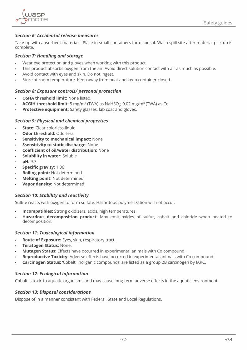
-72-
v7.4
Safety guides
Section 6: Accidental release measuresTake up with absorbent materials. Place in small containers for disposal. Wash spill site after material pick up is complete.
Section 7: Handling and storage • Wear eye protection and gloves when working with this product. • This product absorbs oxygen from the air. Avoid direct solution contact with air as much as possible. • Avoid contact with eyes and skin. Do not ingest. • Store at room temperature. Keep away from heat and keep container closed.
Section 8: Exposure controls/ personal protection • OSHA threshold limit: None listed. • ACGIH threshold limit: 5 mg/m3 (TWA) as NaHSO3; 0.02 mg/m3 (TWA) as Co. • Protective equipment: Safety glasses, lab coat and gloves.
Section 9: Physical and chemical properties • State: Clear colorless liquid • Odor threshold: Odorless • Sensitivity to mechanical impact: None • Ssensitivity to static discharge: None • Coefficient of oil/water distribution: None • Solubility in water: Soluble • pH: 9.7 • Specific gravity: 1.06 • Boiling point: Not determined • Melting point: Not determined • Vapor density: Not determined
Section 10: Stability and reactivitySulfite reacts with oxygen to form sulfate. Hazardous polymerization will not occur.
• Incompatibles: Strong oxidizers, acids, high temperatures. • Hazardous decomposition product: May emit oxides of sulfur, cobalt and chloride when heated to
decomposition.
Section 11: Toxicological information • Route of Exposure: Eyes, skin, respiratory tract. • Teratogen Status: None. • Mutagen Status: Effects have occurred in experimental animals with Co compound. • Reproductive Toxicity: Adverse effects have occurred in experimental animals with Co compound. • Carcinogen Status: ‘Cobalt, inorganic compounds’ are listed as a group 2B carcinogen by IARC.
Section 12: Ecological informationCobalt is toxic to aquatic organisms and may cause long-term adverse effects in the aquatic environment.
Section 13: Disposal considerationsDispose of in a manner consistent with Federal, State and Local Regulations.
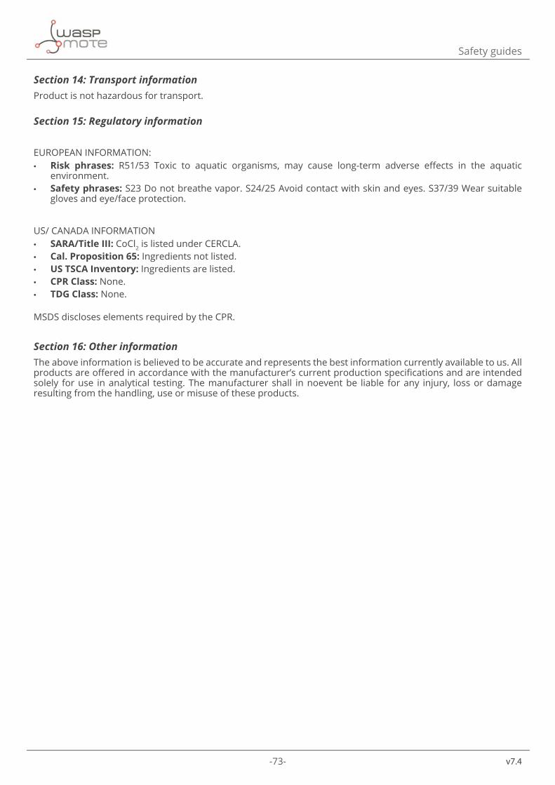
-73- v7.4
Safety guides
Section 14: Transport informationProduct is not hazardous for transport.
Section 15: Regulatory information
EUROPEAN INFORMATION: • Risk phrases: R51/53 Toxic to aquatic organisms, may cause long-term adverse effects in the aquatic
environment. • Safety phrases: S23 Do not breathe vapor. S24/25 Avoid contact with skin and eyes. S37/39 Wear suitable
gloves and eye/face protection.
US/ CANADA INFORMATION • SARA/Title III: CoCl2 is listed under CERCLA. • Cal. Proposition 65: Ingredients not listed. • US TSCA Inventory: Ingredients are listed. • CPR Class: None. • TDG Class: None.
MSDS discloses elements required by the CPR.
Section 16: Other informationThe above information is believed to be accurate and represents the best information currently available to us. All products are offered in accordance with the manufacturer’s current production specifications and are intended solely for use in analytical testing. The manufacturer shall in noevent be liable for any injury, loss or damage resulting from the handling, use or misuse of these products.
-74-
v7.4
Safety guides
8.5. ORP 225mV Calibration SolutionMaterial safety data sheet • UN Number: None Allocated • Dangerous Goods Class: None Allocated • Other Names: Nil • Subsidiary Risk: None Allocated • Hazchem Code: None Allocated • Poisons Schedule: Not Scheduled • Uses: Analytical reagent for calibrating ORP / Redox sensors
#US/Canada/International: 24 Hour Emergency Information Telephone NumbersCHEMTREC (USA): 800.424.9300CANUTEC (Canada): 613.424.6666International 703-527-3887
#Spain: Centro Nacional de ToxicologíaTeléfono: 91 5620420http://institutodetoxicologia.justicia.es/
Physical Description / Properties: • Appearance: Yellow odorless liquid • Boiling Point (ºC): 100 (approx) • Vapour Pressure (mm of Hg @ 25ºC): 25 (approx) • Specific Gravity: 1 • Flash Point (ºC): Not flammable • Flammability Limits (%): Not flammable • Solubility in Water (g/L): Completely miscible
Ingredients:
Chemical Entity CAS NO. ProportionPotassium Chloride 7447-40-7 0.75% w/vPotassium Ferricyanide 13746-66-2 0.11% w/vPotassium Ferrocyanide 14459-95-1 0.14% w/vWater 7732-18-5 to 100%
Health hazard informationHealth Effects: • Swallowed: May be harmful if swallowed. May cause irritation of the gastric system. • Eye: May be irritating to eye tissue. • Skin: May irritate skin tissue. • Inhaled: Not considered a hazard with normal laboratory use. Mists may cause irritation of mucous
membranes. • Chronic Effects: No data available
-75- v7.4
Safety guides
First Aid: • Swallowed: If conscious wash out mouth with water. Seek medical advice. Show this MSDS to medical
practitioner. • Eye: Immediately hold eyelids open and flood with water for at least 15 minutes. Obtain medical aid. Show
this MSDS to medical practitioner. • Skin: Remove contaminated clothing. Immediately wash skin thoroughly with water and mild soap. Seek
medical advice if irritation persists. Show this MSDS to medical practitioner. • Inhaled: Remove from contaminated air. Maintain breathing with artificial respiration if necessary. Seek
medical assistance. Show this MSDS to a doctor.
Advice to Doctor:Treat symptomatically.
Precautions for use • Exposure Limits: Work safe - None Established • Engineering Controls: Not usually required with normal use. If mists or aerosols generated, maintain personal
exposure to minimal concentrations with extraction ventilation. • Personal Protection: Wear protective clothing including safety glasses and rubber or PVC gloves. • Flammability: Not flammable.
Safe handling information • Storage & Transport: Store sealed in original container in a cool well ventilated situation away from foods
and other chemicals. Observe good hygiene and housekeeping practices. No special transport requirements apply.
• Spills & Disposal: Absorb spills with sand or vermiculite. Transfer carefully to disposal container. Dispose of in accordance with local regulations.
• Fire/Explosion Hazard: Fire fighters should wear self contained breathing apparatus and impervious clothing if exposure to fumes is likely. Use water spray, foam or dry chemical to control fire situation if compatible with other chemical products in the vicinity.
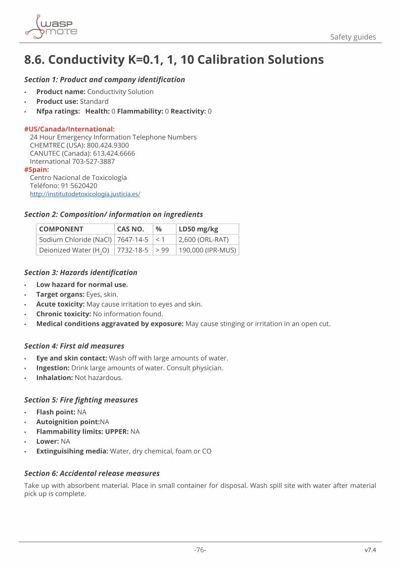
-76-
v7.4
Safety guides
8.6. Conductivity K=0.1, 1, 10 Calibration SolutionsSection 1: Product and company identification • Product name: Conductivity Solution • Product use: Standard • Nfpa ratings: Health: 0 Flammability: 0 Reactivity: 0
#US/Canada/International: 24 Hour Emergency Information Telephone NumbersCHEMTREC (USA): 800.424.9300CANUTEC (Canada): 613.424.6666International 703-527-3887
#Spain: Centro Nacional de ToxicologíaTeléfono: 91 5620420http://institutodetoxicologia.justicia.es/
Section 2: Composition/ information on ingredients
COMPONENT CAS NO. % LD50 mg/kgSodium Chloride (NaCl) 7647-14-5 < 1 2,600 (ORL-RAT)Deionized Water (H2O) 7732-18-5 > 99 190,000 (IPR-MUS)
Section 3: Hazards identification • Low hazard for normal use. • Target organs: Eyes, skin. • Acute toxicity: May cause irritation to eyes and skin. • Chronic toxicity: No information found. • Medical conditions aggravated by exposure: May cause stinging or irritation in an open cut.
Section 4: First aid measures • Eye and skin contact: Wash off with large amounts of water. • Ingestion: Drink large amounts of water. Consult physician. • Inhalation: Not hazardous.
Section 5: Fire fighting measures • Flash point: NA • Autoignition point:NA • Flammability limits: UPPER: NA • Lower: NA • Extinguisihing media: Water, dry chemical, foam or CO
Section 6: Accidental release measuresTake up with absorbent material. Place in small container for disposal. Wash spill site with water after material pick up is complete.
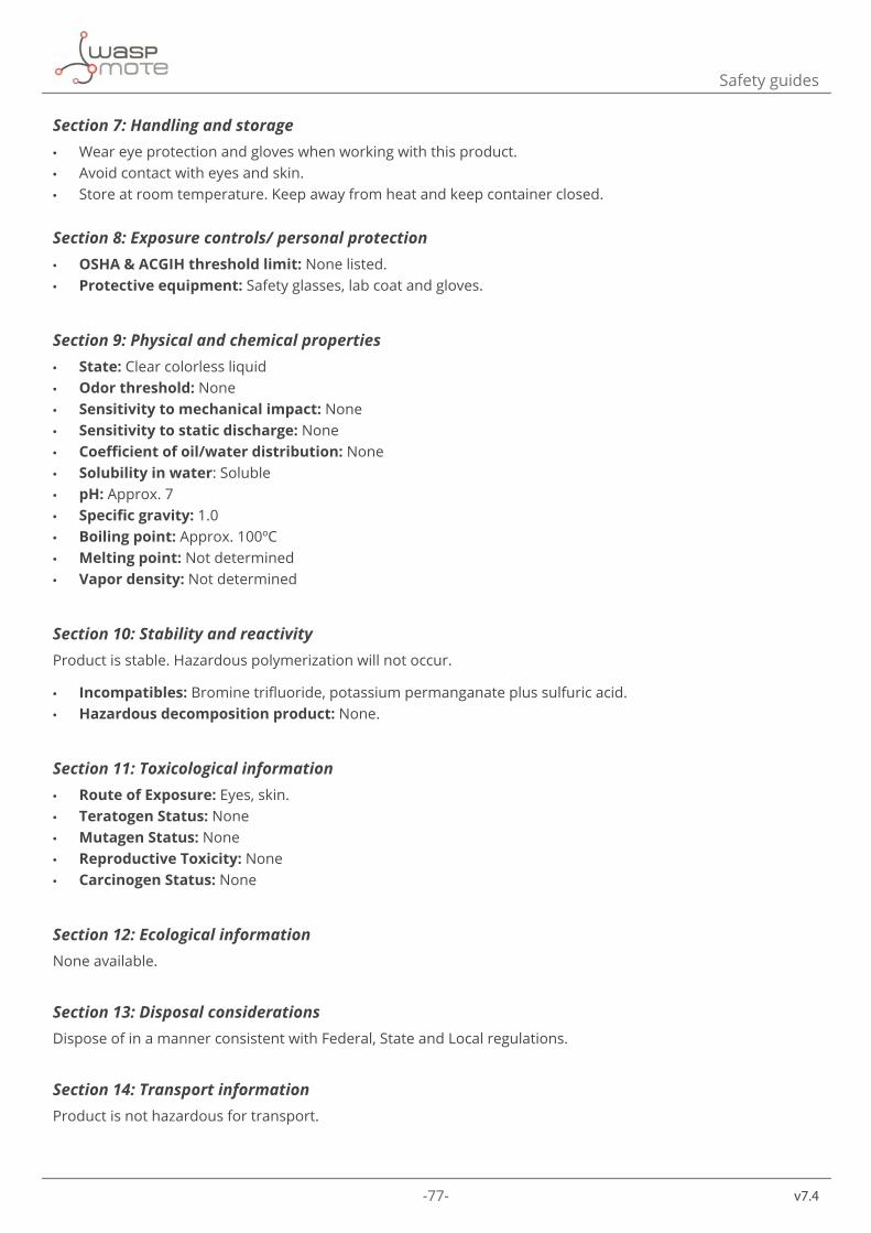
-77- v7.4
Safety guides
Section 7: Handling and storage • Wear eye protection and gloves when working with this product. • Avoid contact with eyes and skin. • Store at room temperature. Keep away from heat and keep container closed.
Section 8: Exposure controls/ personal protection • OSHA & ACGIH threshold limit: None listed. • Protective equipment: Safety glasses, lab coat and gloves.
Section 9: Physical and chemical properties • State: Clear colorless liquid • Odor threshold: None • Sensitivity to mechanical impact: None • Sensitivity to static discharge: None • Coefficient of oil/water distribution: None • Solubility in water: Soluble • pH: Approx. 7 • Specific gravity: 1.0 • Boiling point: Approx. 100ºC • Melting point: Not determined • Vapor density: Not determined
Section 10: Stability and reactivityProduct is stable. Hazardous polymerization will not occur.
• Incompatibles: Bromine trifluoride, potassium permanganate plus sulfuric acid. • Hazardous decomposition product: None.
Section 11: Toxicological information • Route of Exposure: Eyes, skin. • Teratogen Status: None • Mutagen Status: None • Reproductive Toxicity: None • Carcinogen Status: None
Section 12: Ecological informationNone available.
Section 13: Disposal considerationsDispose of in a manner consistent with Federal, State and Local regulations.
Section 14: Transport informationProduct is not hazardous for transport.
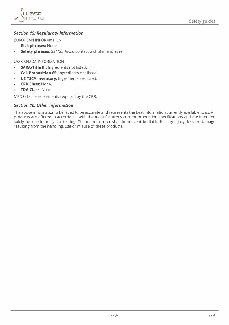
-78-
v7.4
Safety guides
Section 15: Regularoty informationEUROPEAN INFORMATION: • Risk phrases: None • Safety phrases: S24/25 Avoid contact with skin and eyes.
US/ CANADA INFORMATION • SARA/Title III: Ingredients not listed. • Cal. Proposition 65: Ingredients not listed. • US TSCA Inventory: Ingredients are listed. • CPR Class: None. • TDG Class: None.
MSDS discloses elements required by the CPR.
Section 16: Other informationThe above information is believed to be accurate and represents the best information currently available to us. All products are offered in accordance with the manufacturer’s current production specifications and are intended solely for use in analytical testing. The manufacturer shall in noevent be liable for any injury, loss or damage resulting from the handling, use or misuse of these products.

-79- v7.4
API changelog
9. API changelogKeep track of the software changes on this link:
www.libelium.com/development/waspmote/documentation/changelog/#SmartWater
-80-
v7.4
Documentation changelog
10. Documentation changelog
From v7.3 to v7.4
• Changed figure showing the connection of the turbidity sensor
From v7.2 to v7.3
• Added recommendations about sensors lifetime and recalibration • The length of the Pt-1000 sensor cable was updated
From v7.1 to v7.2
• The lengths of the cables of the sensors were updated
From v7.0 to v7.1
• The top image of the board was updated • Added references for the new GPS accessory for Plug & Sense!

-81- v7.4
Certifications
11. CertificationsLibelium offers 2 types of IoT sensor platforms, Waspmote OEM and Plug & Sense!:
• Waspmote OEM is intended to be used for research purposes or as part of a major product so it needs final certification on the client side. More info at: www.libelium.com/products/waspmote
• Plug & Sense! is the line ready to be used out-of-the-box. It includes market certifications. See below the specific list of regulations passed. More info at: www.libelium.com/products/plug-sense
Besides, Meshlium, our multiprotocol router for the IoT, is also certified with the certifications below. Get more info at:
www.libelium.com/products/meshlium
List of certifications for Plug & Sense! and Meshlium:
• CE (Europe) • FCC (US) • IC (Canada) • ANATEL (Brazil) • RCM (Australia) • PTCRB (cellular certification for the US) • AT&T (cellular certification for the US)
Figure: Certifications of the Plug & Sense! product line
You can find all the certification documents at:
www.libelium.com/certifications
-82-
v7.4
Maintenance
12. Maintenance • In this section, the term “Waspmote” encompasses both the Waspmote device itself as well as its modules and
sensor boards. • Take care with the handling of Waspmote, do not drop it, bang it or move it sharply. • Avoid putting the devices in areas of high temperatures since the electronic components may be damaged. • The antennas are lightly threaded to the connector; do not force them as this could damage the connectors. • Do not use any type of paint for the device, which may damage the functioning of the connections and closure
mechanisms.
-83- v7.4
Disposal and recycling
13. Disposal and recycling • In this section, the term “Waspmote” encompasses both the Waspmote device itself as well as its modules and
sensor boards. • When Waspmote reaches the end of its useful life, it must be taken to a recycling point for electronic equipment. • The equipment has to be disposed on a selective waste collection system, different to that of urban solid
waste. Please, dispose it properly. • Your distributor will inform you about the most appropriate and environmentally friendly waste process for
the used product and its packaging.


