Smarter Lifting Edition 3, February 2019 At first glance, collared eyebolts are a simple device. They have an eye at one end which we can connect to our slings and shackles and a thread which we can connect to our payload at the other. Eyenuts are now included The new Standard now includes comprehensive treatment of both eyebolts and eyenuts. Eyebolts have an external thread and eyenuts have an internal thread. This is important because the thread is an important part of the connection to the payload and these threads come in all shapes and sizes. The Substrate It is vital that the threaded connection to the payload is safe and does not over-stress the supporting material with its threaded interface. AS2317.1 calls this supporting material the substrate. Contained within the Standard are clearer rules to set out how strong the substrate material must be. A common pitfall is to fit an eyebolt to material which is simply not strong enough. One of the advantages of grade 4 (lower tensile) eyebolts is that when lifting softer materials, the grade 4 eyebolt can offer a larger thread to use with a soft payload. This is often at a lower cost than a high tensile lifting point of similar overall size. Matching the strength of an eyebolt to its substrate is vital to achieving sufficient strength and the new Standard provides SAFETY, STANDARDS & COMPLIANCE Update to Australian Standard (AS2317.7-2018) for collared eyebolts and eyenuts
Transcript
Smarter LiftingEdition 3, February 2019
At first glance, collared eyebolts are a simple device. They have an eye at one end which we can connect to our slings and shackles and a thread which we can connect to our payload at the other.
Eyenuts are now included
The new Standard now includes comprehensive treatment of both eyebolts and eyenuts. Eyebolts have an external thread and eyenuts have an internal thread.
This is important because the thread is an important part of the connection to the payload and these threads come in all shapes and sizes.
The Substrate
It is vital that the threaded connection to the payload is safe and does not over-stress the supporting material with its threaded interface. AS2317.1 calls this supporting material the substrate.
Contained within the Standard are clearer rules to set out how strong the substrate material must be. A common pitfall is to fit an eyebolt to material which is simply not strong enough. One of the advantages of grade 4 (lower tensile) eyebolts is that when lifting softer materials, the grade 4 eyebolt can offer a larger thread to use with a soft payload. This is often at a lower cost than a high tensile lifting point of similar overall size.
Matching the strength of an eyebolt to its substrate is vital to achieving sufficient strength and the new Standard provides
SAFETY, STANDARDS & COMPLIANCE
Update to Australian Standard (AS2317.7-2018) for collared eyebolts and eyenuts
guidance on a variety of common scenarios, such as use of a nut behind a plain hole, use of reinforcing washers and use with threaded studs. Common questions such as what grade of nut or stud to use and what tolerance on hole size is required are now addressed.
The importance of the collar
Further to this, the role of the collar is now emphasised. With any collared eyebolt it is important to understand what this means and how vital the ‘collar’ of the eyebolt is.
Wherever an eyebolt is loaded in line with the axis of its thread (in a straight line), the central threaded part can contribute fully towards resisting the lifting forces.
Wherever an eyebolt is loaded away from this axis, then the strength is greatly reduced and the collar with the support it provides becomes vital to resisting the lifting forces.
Without the support of the collar, damage in the form of a bent eyebolt is often the end result.
The new Standard provides clearer diagrams and instructions for avoiding this type of damage when the eyebolt collar cannot directly contact the payload, including the use of shims and packing washers.
Ensuring that the collar is fully supported by the payload (substrate) is important for other reasons too. For example, it provides a visual indication as to whether an eyebolt is unwinding itself.
The new Standard also provides guidance in order to avert such risks.
These are all examples of improved use guidance within the Standard, it is not possible to describe all of them here. Readers are urged to examine the Standard for themselves or to engage in suitable training on the subject.
The direction of loading
One of the most important changes to the Standard however is that it has addressed the differences between load rating methodologies that exist between low and high tensile eyebolts.
In general, good quality high tensile eyebolts around the world are marked with the worst case loading orientation in mind. With low tensile eyebolts however, practices vary - but the most common method is to mark the best-case load rating – that is, a straight pull (axial loading).
The old Australian Standard (by the way) avoided this controversy and did not specify any WLL marking.
In order to address the issue, the new Standard has clarified some terminology with the following terms:
• Axial Loading which is a straight pull• Lateral Loading which is a type of side loading that is never
allowed• Transverse Loading also called trunnion loading.
For straight line axial loading, some tolerances are given,
SAFETY, STANDARDS & COMPLIANCE
Update to Australian Standard (AS2317.7-2018) for collared eyebolts and eyenuts
Smarter Lifting
because nothing is ever perfect. For axial loading to apply, the true direction of force needs to be within 5° of perfectly axial.
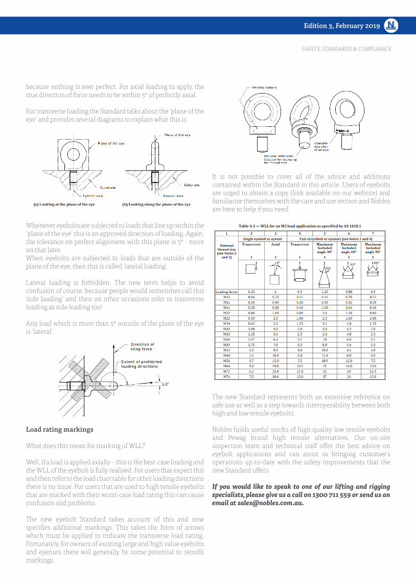
For transverse loading the Standard talks about the ‘plane of the eye’ and provides several diagrams to explain what this is.
Whenever eyebolts are subjected to loads that line up within the ‘plane of the eye’ this is an approved direction of loading. Again, the tolerance on perfect alignment with this plane is 5° - more on that later.When eyebolts are subjected to loads that are outside of the plane of the eye, then this is called ‘lateral loading’.
Lateral loading is forbidden. The new term helps to avoid confusion of course, because people would sometimes call this ‘side loading’ and then on other occasions refer to transverse loading as side loading too!
Any load which is more than 5° outside of the plane of the eye is ‘lateral’.
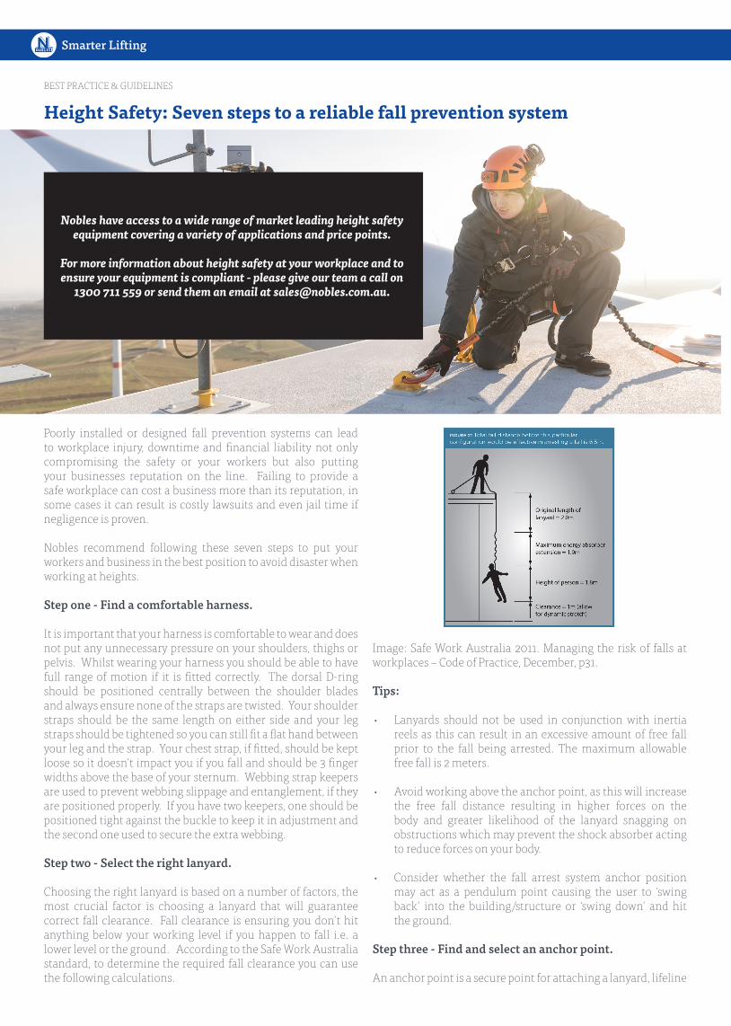
Load rating markings
What does this mean for marking of WLL?
Well, if a load is applied axially – this is the best-case loading and the WLL of the eyebolt is fully realised. For users that expect this and then refer to the load chart table for other loading directions there is no issue. For users that are used to high tensile eyebolts that are marked with their worst-case load rating this can cause confusion and problems.
The new eyebolt Standard takes account of this and now specifies additional markings. This takes the form of arrows which must be applied to indicate the transverse load rating. Fortunately, for owners of existing large and high value eyebolts and eyenuts there will generally be some potential to retrofit markings.
It is not possible to cover all of the advice and additions contained within the Standard in this article. Users of eyebolts are urged to obtain a copy (link available on our website) and familiarise themselves with the care and use section and Nobles are here to help if you need.
The new Standard represents both an extensive reference on safe use as well as a step towards interoperability between both high and low tensile eyebolts.
Nobles holds useful stocks of high quality low tensile eyebolts and Pewag brand high tensile alternatives. Our on-site inspection team and technical staff offer the best advice on eyebolt applications and can assist in bringing customer’s operations up-to-date with the safety improvements that the new Standard offers.
If you would like to speak to one of our lifting and rigging specialists, please give us a call on 1300 711 559 or send us an email at [email protected].
SAFETY, STANDARDS & COMPLIANCE
Edition 3, February 2019
Smarter Lifting
Poorly installed or designed fall prevention systems can lead to workplace injury, downtime and financial liability not only compromising the safety or your workers but also putting your businesses reputation on the line. Failing to provide a safe workplace can cost a business more than its reputation, in some cases it can result is costly lawsuits and even jail time if negligence is proven.
Nobles recommend following these seven steps to put your workers and business in the best position to avoid disaster when working at heights.
Step one - Find a comfortable harness.
It is important that your harness is comfortable to wear and does not put any unnecessary pressure on your shoulders, thighs or pelvis. Whilst wearing your harness you should be able to have full range of motion if it is fitted correctly. The dorsal D-ring should be positioned centrally between the shoulder blades and always ensure none of the straps are twisted. Your shoulder straps should be the same length on either side and your leg straps should be tightened so you can still fit a flat hand between your leg and the strap. Your chest strap, if fitted, should be kept loose so it doesn’t impact you if you fall and should be 3 finger widths above the base of your sternum. Webbing strap keepers are used to prevent webbing slippage and entanglement, if they are positioned properly. If you have two keepers, one should be positioned tight against the buckle to keep it in adjustment and the second one used to secure the extra webbing.
Step two - Select the right lanyard.
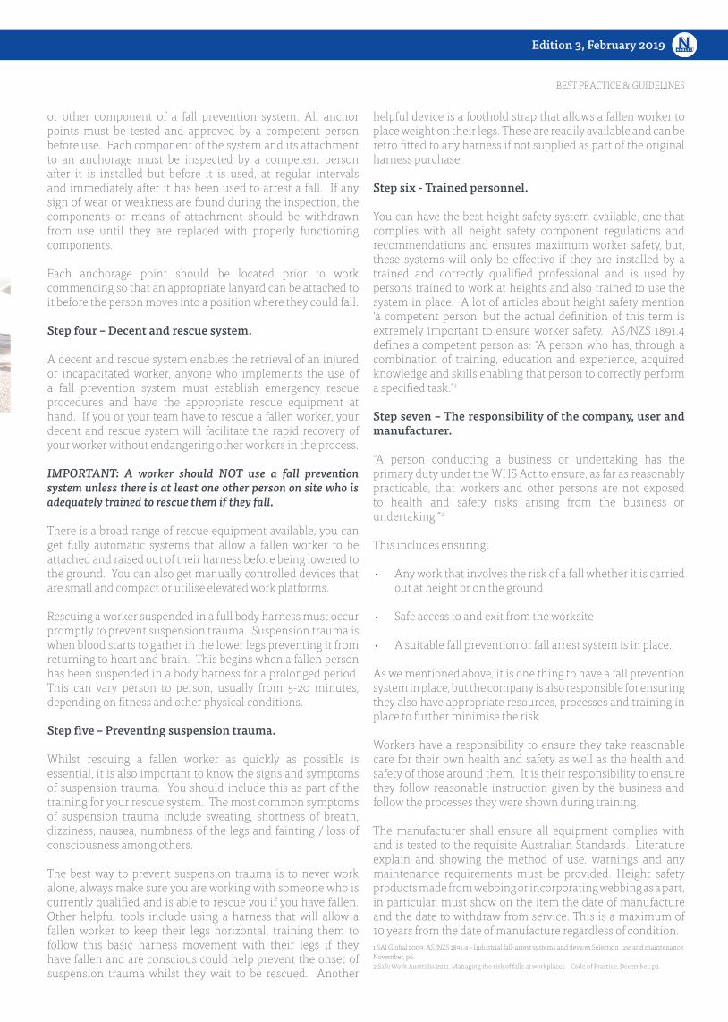
Choosing the right lanyard is based on a number of factors, the most crucial factor is choosing a lanyard that will guarantee correct fall clearance. Fall clearance is ensuring you don’t hit anything below your working level if you happen to fall i.e. a lower level or the ground. According to the Safe Work Australia standard, to determine the required fall clearance you can use the following calculations.
Image: Safe Work Australia 2011. Managing the risk of falls at workplaces – Code of Practice, December, p31.
Tips:
• Lanyards should not be used in conjunction with inertia reels as this can result in an excessive amount of free fall prior to the fall being arrested. The maximum allowable free fall is 2 meters.
• Avoid working above the anchor point, as this will increase the free fall distance resulting in higher forces on the body and greater likelihood of the lanyard snagging on obstructions which may prevent the shock absorber acting to reduce forces on your body.
• Consider whether the fall arrest system anchor position may act as a pendulum point causing the user to ‘swing back’ into the building/structure or ‘swing down’ and hit the ground.
Step three - Find and select an anchor point.
An anchor point is a secure point for attaching a lanyard, lifeline
BEST PRACTICE & GUIDELINES
Height Safety: Seven steps to a reliable fall prevention system
Nobles have access to a wide range of market leading height safety equipment covering a variety of applications and price points.
For more information about height safety at your workplace and to ensure your equipment is compliant - please give our team a call on
or other component of a fall prevention system. All anchor points must be tested and approved by a competent person before use. Each component of the system and its attachment to an anchorage must be inspected by a competent person after it is installed but before it is used, at regular intervals and immediately after it has been used to arrest a fall. If any sign of wear or weakness are found during the inspection, the components or means of attachment should be withdrawn from use until they are replaced with properly functioning components.
Each anchorage point should be located prior to work commencing so that an appropriate lanyard can be attached to it before the person moves into a position where they could fall.
Step four – Decent and rescue system.
A decent and rescue system enables the retrieval of an injured or incapacitated worker, anyone who implements the use of a fall prevention system must establish emergency rescue procedures and have the appropriate rescue equipment at hand. If you or your team have to rescue a fallen worker, your decent and rescue system will facilitate the rapid recovery of your worker without endangering other workers in the process.
IMPORTANT: A worker should NOT use a fall prevention system unless there is at least one other person on site who is adequately trained to rescue them if they fall.
There is a broad range of rescue equipment available, you can get fully automatic systems that allow a fallen worker to be attached and raised out of their harness before being lowered to the ground. You can also get manually controlled devices that are small and compact or utilise elevated work platforms.
Rescuing a worker suspended in a full body harness must occur promptly to prevent suspension trauma. Suspension trauma is when blood starts to gather in the lower legs preventing it from returning to heart and brain. This begins when a fallen person has been suspended in a body harness for a prolonged period. This can vary person to person, usually from 5-20 minutes, depending on fitness and other physical conditions.
Step five – Preventing suspension trauma.
Whilst rescuing a fallen worker as quickly as possible is essential, it is also important to know the signs and symptoms of suspension trauma. You should include this as part of the training for your rescue system. The most common symptoms of suspension trauma include sweating, shortness of breath, dizziness, nausea, numbness of the legs and fainting / loss of consciousness among others.
The best way to prevent suspension trauma is to never work alone, always make sure you are working with someone who is currently qualified and is able to rescue you if you have fallen. Other helpful tools include using a harness that will allow a fallen worker to keep their legs horizontal, training them to follow this basic harness movement with their legs if they have fallen and are conscious could help prevent the onset of suspension trauma whilst they wait to be rescued. Another
helpful device is a foothold strap that allows a fallen worker to place weight on their legs. These are readily available and can be retro fitted to any harness if not supplied as part of the original harness purchase.
Step six - Trained personnel.
You can have the best height safety system available, one that complies with all height safety component regulations and recommendations and ensures maximum worker safety, but, these systems will only be effective if they are installed by a trained and correctly qualified professional and is used by persons trained to work at heights and also trained to use the system in place. A lot of articles about height safety mention ‘a competent person’ but the actual definition of this term is extremely important to ensure worker safety. AS/NZS 1891.4 defines a competent person as: “A person who has, through a combination of training, education and experience, acquired knowledge and skills enabling that person to correctly perform a specified task.”1
Step seven – The responsibility of the company, user and manufacturer.
“A person conducting a business or undertaking has the primary duty under the WHS Act to ensure, as far as reasonably practicable, that workers and other persons are not exposed to health and safety risks arising from the business or undertaking.”2
This includes ensuring:
• Any work that involves the risk of a fall whether it is carried out at height or on the ground
• Safe access to and exit from the worksite
• A suitable fall prevention or fall arrest system is in place.
As we mentioned above, it is one thing to have a fall prevention system in place, but the company is also responsible for ensuring they also have appropriate resources, processes and training in place to further minimise the risk.
Workers have a responsibility to ensure they take reasonable care for their own health and safety as well as the health and safety of those around them. It is their responsibility to ensure they follow reasonable instruction given by the business and follow the processes they were shown during training.
The manufacturer shall ensure all equipment complies with and is tested to the requisite Australian Standards. Literature explain and showing the method of use, warnings and any maintenance requirements must be provided. Height safety products made from webbing or incorporating webbing as a part, in particular, must show on the item the date of manufacture and the date to withdraw from service. This is a maximum of 10 years from the date of manufacture regardless of condition. 1 SAI Global 2009. AS/NZS 1891.4 – Industrial fall-arrest systems and devices Selection, use and maintenance, November, p6.2 Safe Work Australia 2011. Managing the risk of falls at workplaces – Code of Practice, December, p3.
BEST PRACTICE & GUIDELINES
Smarter Lifting
SOLUTIONS & CASE STUDIES
Our technicians responded to a call out for an inspection of a jib crane that had been damaged in service. The crane had been ‘Tagged Out of Service’ and could not be used or placed back in service until assessment or repair was completed by a competent person, in this case, Nobles crane service technicians.
Once onsite our technician conducted an inspection and it was apparent that the jib crane was knocked and the jib mounting plate was now slightly dislodged from the concrete. The anchors were loose and the base plate had moved away from the floor showing a gap between the underside of the plate and the concrete floor (see image 1). Further discussions with the customer indicated that the jib crane was knocked by a forklift when trying to unload a pallet.
Image 1
Working in tight space restrictions it was initially thought that the jib base plate could be moved slightly and new holes could be drilled and new anchors fitted. This was decided against as the new holes needed to be at least 120mm from the existing holes or voids. This would have also decreased the integrity of the concrete therefore causing an unsafe working environment. After discussions it was then decided to replace the concrete under the jib to ensure the floor was structurally sound and the jib crane cold be mounted back in its original position.
Nobles crane technicians first removed the jib from the floor to see what damage was done to the concrete and if any damage was done the jib crane itself. As it was only a slight knock the jib crane itself was not damaged and could be reused.
The first step was to repair the concrete floor, Nobles outsourced this to an approved local concrete company. The original concrete area was cut out and removed and replaced with new concrete as per engineering specification. Previous engineer reports were also used to assist in providing the correct strength
and mix of the concrete. Once the concrete was completed it was left to set and strengthen to ensure a strong foundation for the jib crane to be mounted on.
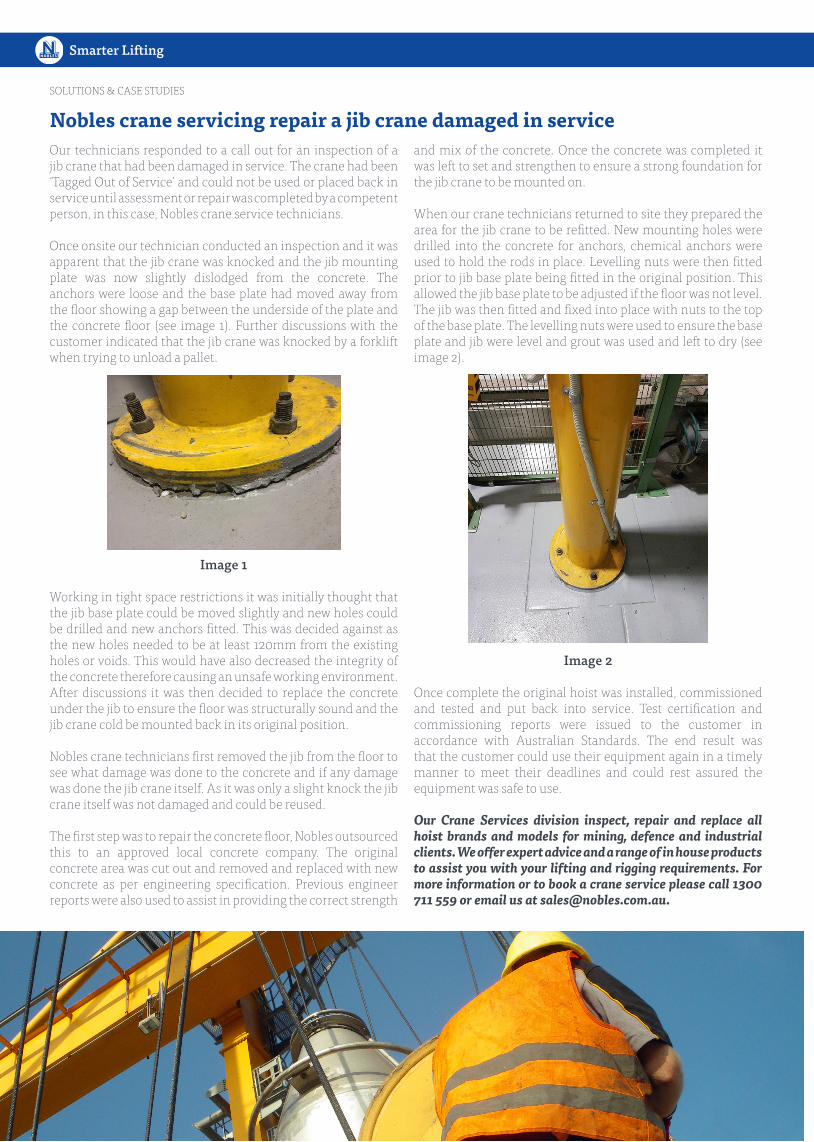
When our crane technicians returned to site they prepared the area for the jib crane to be refitted. New mounting holes were drilled into the concrete for anchors, chemical anchors were used to hold the rods in place. Levelling nuts were then fitted prior to jib base plate being fitted in the original position. This allowed the jib base plate to be adjusted if the floor was not level. The jib was then fitted and fixed into place with nuts to the top of the base plate. The levelling nuts were used to ensure the base plate and jib were level and grout was used and left to dry (see image 2).
Image 2
Once complete the original hoist was installed, commissioned and tested and put back into service. Test certification and commissioning reports were issued to the customer in accordance with Australian Standards. The end result was that the customer could use their equipment again in a timely manner to meet their deadlines and could rest assured the equipment was safe to use.
Our Crane Services division inspect, repair and replace all hoist brands and models for mining, defence and industrial clients. We offer expert advice and a range of in house products to assist you with your lifting and rigging requirements. For more information or to book a crane service please call 1300 711 559 or email us at [email protected].
Nobles crane servicing repair a jib crane damaged in service
Edition 3, February 2019
NEW PRODUCT RELEASES & NEWS
It has been just over one year since A. Noble & Son Limited (Nobles) and Bridon-Bekaert Ropes Group Australia (BBRG) announced their new long term national distribution agreement in November 2017. This agreement provided for Nobles to nationally distribute Bridon and WRI branded high-performance crane, industrial and mining ropes to Australian customers.
Nobles and BBRG have already collaborated on many joint customer projects, partnered at the recent CICA conference, and presented and exhibited at the largest Australian mining conference IMARC, recently held in Melbourne. Nobles sales of BBRG ropes have soared due to an increase in Bridon wire rope stocks being held by Nobles in all mainland states across Australia. These increased stock levels, with now over 100,000 metres of high-performance Bridon wire rope across a vast breadth of types and sizes (see below), have allowed orders to be processed and dispatched faster than ever before.
Bridon-Bekaert VP Oceania, Stuart Callender says “We have seen really positive results from our partnership with Nobles with the growth of our high-performance ropes in Australia being driven by our collaboration with the Nobles team. For example, the close work between Nobles and BBRG has substantially grown our sales into the mobile, tower and port crane sectors nationally”.
Nobles Managing Director, Guy Roberts has enjoyed seeing this partnership go from strength to strength over the past year and as a result the products have been flying off the shelves. “Sales of the new range of Bridon wire rope have been increasing with each passing month,” says Mr Roberts. “We have sold out
steadily increasing volumes of BBRG’s high performance wire rope and are on track to exceed our joint growth target for the next financial year.”
Mr Roberts said that, “Customers are appreciating the stronger performance attributes of BBRG wire rope, faster delivery that comes with new local stocking, combined with smarter advice from the combined technical resources of BBRG, the world’s largest wire rope manufacturer and Nobles, Australia’s leading lifting and rigging specialist.”
Nobles is now stocking across its national network over 25,000 metres of stock of Bridon Dyform 34LR in sizes 16-32mm, over 15,000 metres of Dyform 34LR PI in sizes 14-34mm, over 55,000 meters of Dyform 8PI in sizes 10-32mm and over 5,000m of Dyform DSC8 in sizes 8-14mm, across a variety of constructions in both 1960 and 2160 grades.
For more information on the Bridon wire rope available or to place an order, please call our team on 1300 711 559 or send them an email at [email protected].
Nobles and BBRG wire rope distribution partnership going strong
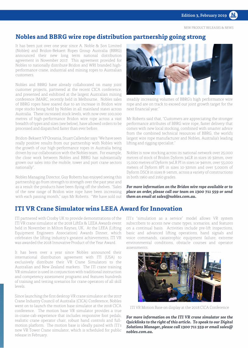
ITI partnered with Crosby UK to provide demonstrations of the ITI VR crane simulator at the 2018 LiftEx & LEEA Awards event held in November in Milton Keynes, UK. At the LEEA (Lifting Equipment Engineers Association) Awards Dinner, which celebrates the lifting industry’s greatest achievements, ITI VR was awarded the 2018 Innovative Product of the Year Award.
It has been over a year since Nobles announced their international distribution agreement with ITI (USA) to exclusively distribute their VR Crane Simulators to the Australian and New Zealand markets. The ITI crane training VR simulator is used in conjunction with traditional instruction and competency assessment programs and features hundreds of training and testing scenarios for crane operators of all skill levels.
Since launching the first desktop VR crane simulator at the 2017 Crane Industry Council of Australia (CICA) Conference, Nobles went on to launch the motion base simulator at the 2018 CICA conference. The motion base VR simulator provides a true in-crane-cab experience that includes responsive foot pedals, realistic crane operator chair, robust hand controls and full-motion platform. The motion base is ideally paired with ITI’s new VR Tower Crane simulator, which is scheduled for public release in February.
ITI’s “simulation as a service” model allows VR system subscribers to access new crane types, scenarios, and features on a continual basis. Activities include pre-lift inspections, basic and advanced lifting operations, hand signals and voice commands, catastrophic equipment failure, extreme environmental conditions, obstacle courses and operator assessments.
ITI VR Motion Base on display at the 2018 CICA Conference
For more information on the ITI VR crane simulator see the Quicklinks to the right of this article. To speak to our Digital Solutions Manager, please call 1300 711 559 or email [email protected].
ITI VR Crane Simulator wins LEEA Award for Innovation
RAPTOR redefines the concept of safety since it has two fall indicators that are visible to every user. Other smart details include the flexible inlet dampers, the linear force distribution and unequivocal anchor point. Thanks to its sophisticated design, RAPTOR also inspires when it comes to storage, maintenance and durability. All fall arresters are compliant to AS/NZS 1891.3:1997 and can secure a person with a maximum user weight of 140 kg.
Five Year RecertificationA six-monthly inspection is required by a competent person however recertification by Skylotec or a certified service agent is only required every 5 years. This is due to high quality design and manufacturing from our German production facility.
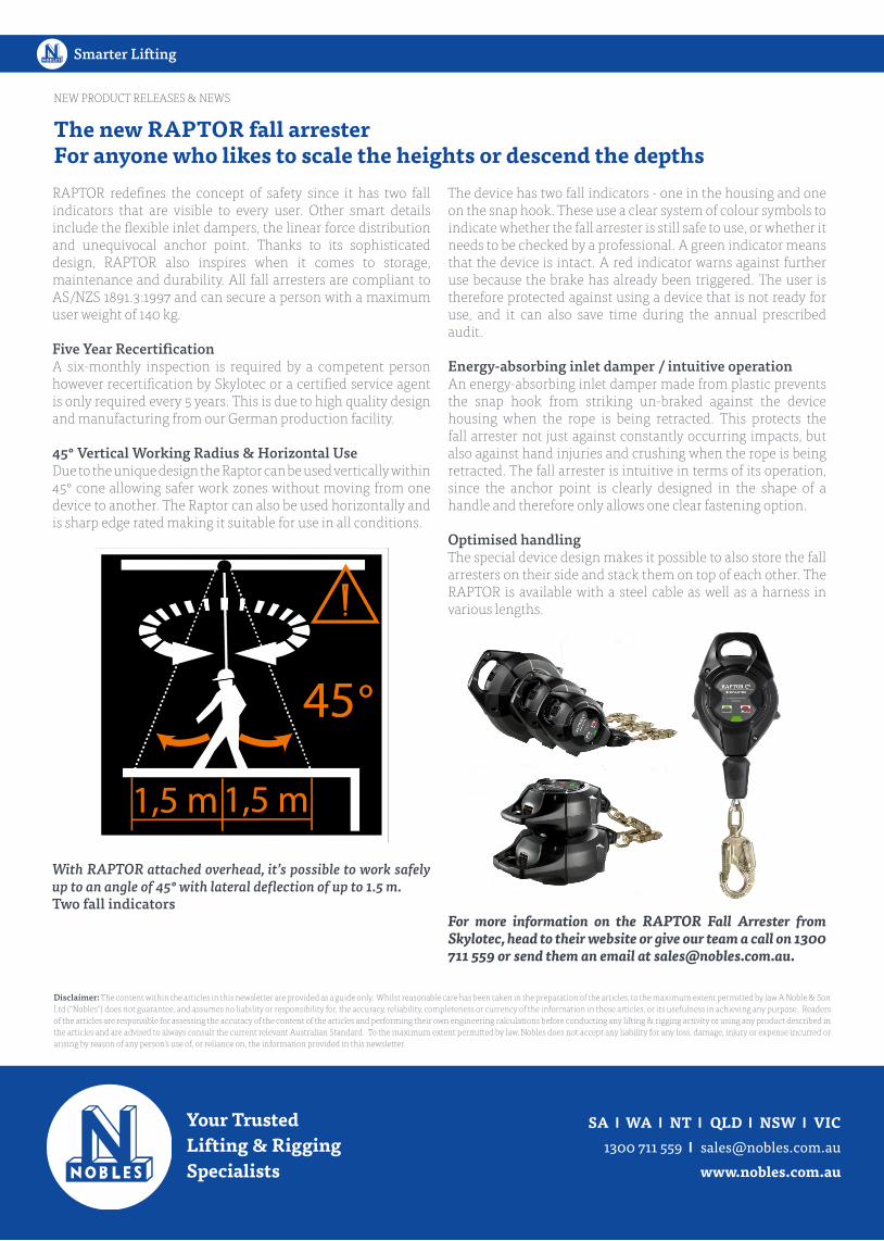
45° Vertical Working Radius & Horizontal UseDue to the unique design the Raptor can be used vertically within 45° cone allowing safer work zones without moving from one device to another. The Raptor can also be used horizontally and is sharp edge rated making it suitable for use in all conditions.
With RAPTOR attached overhead, it’s possible to work safely up to an angle of 45° with lateral deflection of up to 1.5 m.Two fall indicators
The device has two fall indicators - one in the housing and one on the snap hook. These use a clear system of colour symbols to indicate whether the fall arrester is still safe to use, or whether it needs to be checked by a professional. A green indicator means that the device is intact. A red indicator warns against further use because the brake has already been triggered. The user is therefore protected against using a device that is not ready for use, and it can also save time during the annual prescribed audit.
Energy-absorbing inlet damper / intuitive operationAn energy-absorbing inlet damper made from plastic prevents the snap hook from striking un-braked against the device housing when the rope is being retracted. This protects the fall arrester not just against constantly occurring impacts, but also against hand injuries and crushing when the rope is being retracted. The fall arrester is intuitive in terms of its operation, since the anchor point is clearly designed in the shape of a handle and therefore only allows one clear fastening option.
Optimised handlingThe special device design makes it possible to also store the fall arresters on their side and stack them on top of each other. The RAPTOR is available with a steel cable as well as a harness in various lengths.
For more information on the RAPTOR Fall Arrester from Skylotec, head to their website or give our team a call on 1300 711 559 or send them an email at [email protected].
The new RAPTOR fall arresterFor anyone who likes to scale the heights or descend the depths
Disclaimer: The content within the articles in this newsletter are provided as a guide only. Whilst reasonable care has been taken in the preparation of the articles, to the maximum extent permitted by law A Noble & Son Ltd (“Nobles”) does not guarantee, and assumes no liability or responsibility for, the accuracy, reliability, completeness or currency of the information in these articles, or its usefulness in achieving any purpose. Readers of the articles are responsible for assessing the accuracy of the content of the articles and performing their own engineering calculations before conducting any lifting & rigging activity or using any product described in the articles and are advised to always consult the current relevant Australian Standard. To the maximum extent permitted by law, Nobles does not accept any liability for any loss, damage, injury or expense incurred or arising by reason of any person’s use of, or reliance on, the information provided in this newsletter.