76
SmartPilot X-5 Wheel Installation & Setup Guide Document reference: 87074-4 Date: July 2012
| Date post: | 16-May-2018 |
| Category: |
Documents |
| Upload: | duongxuyen |
| View: | 220 times |
| Download: | 1 times |
SmartPilot X-5Wheel Installation & Setup Guide
Document reference: 87074-4
Date: July 2012

Autohelm, HSB, RayTech Navigator, Sail Pilot, SeaTalk and Sportpilot are UK registered trademarks of Raymarine UK Limited.
Pathfinder and Raymarine are UK registered trademarks of Raymarine Holdings Limited.
45STV, 60STV, AST, Autoadapt, AutoGST, AutoSeastate, AutoTrim, Bidata, G Series, HDFI, LifeTag, Marine Intelligence, Maxi-view, On Board, Raychart, Raynav, Raypilot, RayTalk, Raystar, ST40, ST60+, Seaclutter, Smart Route, Tridata and Waypoint
Navigation are trademarks of Raymarine UK Limited.
All other product names are trademarks or registered trademarks of their respective owners.
© Handbook contents copyright Raymarine Ltd 2012
Contents i
ContentsPreface ............................................................................................................................v
Safety notices .......................................................................................................... vEMC Conformance .................................................................................................. vLimitations on pressure washing .............................................................................. vProduct documents ..................................................................................................viWarranty ..................................................................................................................viProduct disposal ......................................................................................................vi
Waste Electrical and Electronic (WEEE) Directive ...................................vi
Chapter 1:Installation and system overviews ................................................... 11.1 Installation overview .................................................................................... 1
Planning....................................................................................................... 1Installing....................................................................................................... 1
1.2 Safe and successful installation ................................................................... 1Certified installation...................................................................................... 1Getting assistance........................................................................................ 1
1.3 System overviews ....................................................................................... 2Marine electronics systems .......................................................................... 2
Example SeaTalk system......................................................................... 31.4 Equipment & tools ....................................................................................... 4
Parts supplied .............................................................................................. 4Tools and equipment NOT supplied.............................................................. 5
Tools:........................................................................................................ 5Cables / equipment................................................................................... 5Optional equipment .................................................................................. 5
1.5 Create a schematic diagram ........................................................................ 5
Chapter 2:Installing the system ............................................................................. 72.1 Installation precautions ................................................................................ 7
EMC installation guidelines .......................................................................... 7Remember ................................................................................................ 7
Suppression ferrites.................................................................................. 8Connections to other equipment............................................................... 8Compass .................................................................................................. 8
2.2 General cabling guidelines .......................................................................... 8Power cable requirement ............................................................................. 8
2.3 SPX-5 Wheel system Course Computer ...................................................... 9Mounting ...................................................................................................... 9Connection overview...................................................................................11
2.4 Mounting the Wheel Drive ...........................................................................11Introduction .................................................................................................11Step 1 –Drill the spoke clamp holes ............................................................ 12Step 2 –Secure the wheel drive to the wheel............................................... 14Step 3 – Attach the pedestal bracket........................................................... 15
Motor tube location ................................................................................. 15Pedestal bracket – length and position................................................... 16
Wheel Drive electrical connection............................................................... 19Wheel Drive cable routing ...................................................................... 20
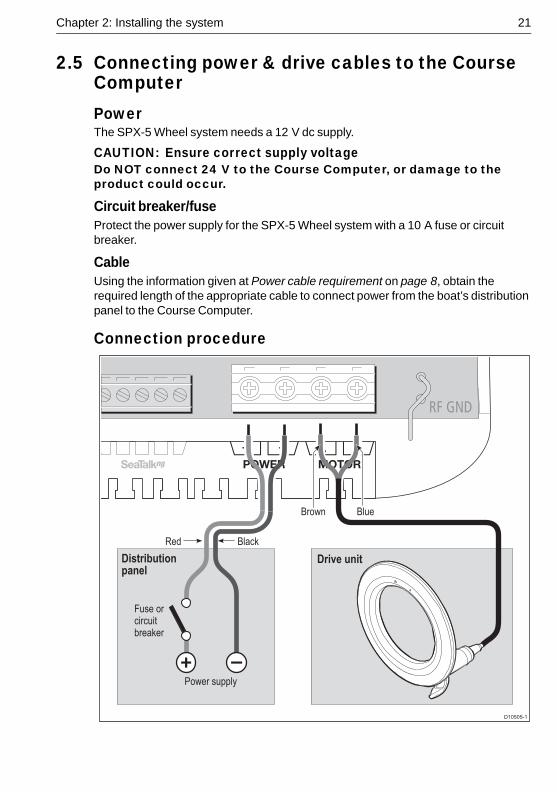
2.5 Connecting power & drive cables to the Course Computer ........................ 21Power......................................................................................................... 21
Circuit breaker/fuse ................................................................................ 21
ii SmartPilot Wheel Installation & Setup Guide
Cable ...................................................................................................... 21Connection procedure................................................................................ 21
2.6 Fluxgate Compass ..................................................................................... 22Compass mounting .................................................................................... 22
Location .................................................................................................. 22Mounting procedure................................................................................ 23
Compass connection.................................................................................. 232.7 Pilot Controller ........................................................................................... 24
Fitting...................................................................................................... 24Connecting to SeaTalk................................................................................ 24
SeaTalk power connections ................................................................... 242.8 Connect to ground ..................................................................................... 262.9 Optional connections ................................................................................. 27
Rudder reference ....................................................................................... 27SeaTalkng Connections ............................................................................. 28
SeaTalkng power.................................................................................... 28See also.................................................................................................. 28
NMEA 0183 equipment .............................................................................. 29Data bridging .......................................................................................... 29NMEA 0183 / Connecting other manufacturers’ equipment ................... 29
2.10 Final checks ............................................................................................... 30Secure all cables ........................................................................................ 30
2.11 Commission the system before use ........................................................... 30
Chapter 3:Commissioning & setup ...................................................................... 31Requirement .............................................................................................. 31
3.1 Commissioning .......................................................................................... 31Dockside checks & setup............................................................................ 31
Switching on ........................................................................................... 31Checking SeaTalk and NMEA 0183 connections................................... 32
SeaTalk instruments ................................................................................32SeaTalk and NMEA GPS or Chartplotter .................................................32Other NMEA 0183 connections ..............................................................32
Checking autopilot operating sense ....................................................... 32Setting the vessel and drive type............................................................ 33
Set the vessel type ..................................................................................34Set the drive type .....................................................................................34
Align the rudder indicator........................................................................ 34Set the rudder limits................................................................................ 34Save the new settings ............................................................................ 35
Seatrial calibration...................................................................................... 35Important ................................................................................................ 35Seatrial conditions .................................................................................. 35Compass calibration ............................................................................... 35
Swinging the compass ............................................................................35Aligning the compass heading ................................................................37
AutoLearn ............................................................................................... 38Commissioning complete ........................................................................... 40
3.2 Manual setup ............................................................................................. 41Checking SPX-5 Wheel system operation .................................................. 41Response level........................................................................................... 41Rudder gain................................................................................................ 42
Checking................................................................................................. 42Adjusting................................................................................................. 42
Counter rudder .......................................................................................... 43
Contents iii
Checking................................................................................................. 43Adjusting................................................................................................. 43
AutoTrim .................................................................................................... 43Adjusting................................................................................................. 43
Chapter 4:SPX-5 Wheel system settings ........................................................... 454.1 Introduction ............................................................................................... 45
Calibration modes ...................................................................................... 45Display calibration .................................................................................. 45User calibration....................................................................................... 45Seatrial calibration .................................................................................. 45Dealer calibration.................................................................................... 45
Accessing the Calibration modes ............................................................... 46Adjusting calibration values........................................................................ 46
4.2 Display calibration ..................................................................................... 47RUDD BAR screen..................................................................................... 47HDG screen ............................................................................................... 47Data pages ................................................................................................ 47
Setting up data pages............................................................................. 484.3 User calibration ......................................................................................... 49
AutoTack .................................................................................................... 50Gybe inhibit ................................................................................................ 50Wind selection............................................................................................ 50WindTrim.................................................................................................... 50Response level........................................................................................... 50
4.4 Dealer calibration ...................................................................................... 51Seatrial calibration lock .............................................................................. 52Vessel type ................................................................................................ 52Drive type .................................................................................................. 53Align rudder................................................................................................ 53Rudder limit ............................................................................................... 53Rudder gain ............................................................................................... 53Counter rudder ........................................................................................... 53Rudder damping......................................................................................... 54AutoTrim .................................................................................................... 54Response level .......................................................................................... 54Turn rate limit.............................................................................................. 55Off course angle ......................................................................................... 55AutoTack .................................................................................................... 55Gybe inhibit ................................................................................................ 56Wind selection............................................................................................ 56WindTrim.................................................................................................... 56PowerSteer ................................................................................................ 56Cruise speed .............................................................................................. 56Latitude ...................................................................................................... 56System reset .............................................................................................. 57
4.5 System defaults ......................................................................................... 57

iv SmartPilot Wheel Installation & Setup Guide
Appendix 1:NMEA 0183 sentences .................................................................... 59NMEA0183 to Course Computer ...........................................................................59NMEA0183 from Course Computer .......................................................................59
Appendix 2:SPX-5 Wheel system specifications ............................................ 61Course Computer ...................................................................................................61Wheel Drive ............................................................................................................62Pilot Controller (ST6002) ........................................................................................63
Index.............................................................................................................................. 65
v
ContentsPreface
Safety notices
EMC ConformanceAll Raymarine equipment and accessories are designed to the best industry standards for use in the recreational marine environment. Their design and manufacture conforms to the appropriate Electromagnetic Compatibility (EMC) standards, but correct installation is required to ensure that performance is not compromised.
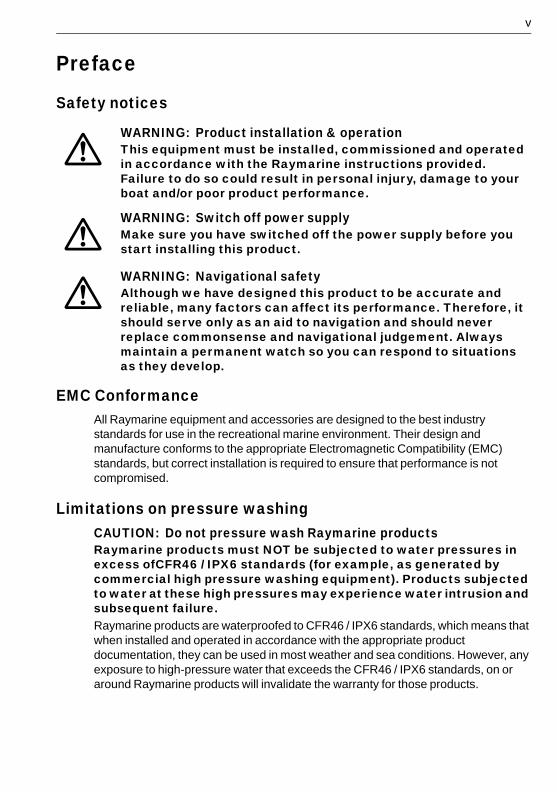
Limitations on pressure washingCAUTION: Do not pressure wash Raymarine productsRaymarine products must NOT be subjected to water pressures in excess ofCFR46 / IPX6 standards (for example, as generated by commercial high pressure washing equipment). Products subjected to water at these high pressures may experience water intrusion and subsequent failure. Raymarine products are waterproofed to CFR46 / IPX6 standards, which means that when installed and operated in accordance with the appropriate product documentation, they can be used in most weather and sea conditions. However, any exposure to high-pressure water that exceeds the CFR46 / IPX6 standards, on or around Raymarine products will invalidate the warranty for those products.
WARNING: Product installation & operationThis equipment must be installed, commissioned and operated in accordance with the Raymarine instructions provided. Failure to do so could result in personal injury, damage to your boat and/or poor product performance.
WARNING: Switch off power supplyMake sure you have switched off the power supply before you start installing this product.
WARNING: Navigational safetyAlthough we have designed this product to be accurate and reliable, many factors can affect its performance. Therefore, it should serve only as an aid to navigation and should never replace commonsense and navigational judgement. Always maintain a permanent watch so you can respond to situations as they develop.
vi SmartPilot X-5 Wheel Installation & Setup Guide
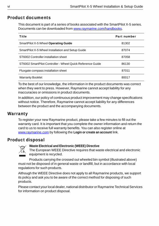
Product documentsThis document is part of a series of books associated with the SmartPilot X-5 series. Documents can be downloaded from www.raymarine.com/handbooks.
To the best of our knowledge, the information in the product documents was correct when they went to press. However, Raymarine cannot accept liability for any inaccuracies or omissions in product documents.
In addition, our policy of continuous product improvement may change specifications without notice. Therefore, Raymarine cannot accept liability for any differences between the product and the accompanying documents.
WarrantyTo register your new Raymarine product, please take a few minutes to fill out the warranty card. It is important that you complete the owner information and return the card to us to receive full warranty benefits. You can also register online at www.raymarine.com by following the Login or create an account link.
Product disposalWaste Electrical and Electronic (WEEE) DirectiveThe European WEEE Directive requires that waste electrical and electronic equipment is recycled.
Products carrying the crossed out wheeled bin symbol (illustrated above) must not be disposed of in general waste or landfill, but in accordance with local regulations for such products.
Although the WEEE Directive does not apply to all Raymarine products, we support its policy and ask you to be aware of the correct method for disposing of such products.
Please contact your local dealer, national distributor or Raymarine Technical Services for information on product disposal.
Title Part number
SmartPilot X-5 Wheel Operating Guide 81302
SmartPilot X-5 Wheel Installation and Setup Guide 87074
ST6002 Controller installation sheet 87058
ST6002 SmartPilot Controller - Wheel Quick Reference Guide 86130
Fluxgate compass installation sheet 87011
Warranty Booklet 80017
1
Chapter 1: Installation and system overviewsThis chapter gives an overview of installation procedures and network configurations for an SPX -5 Wheel system.
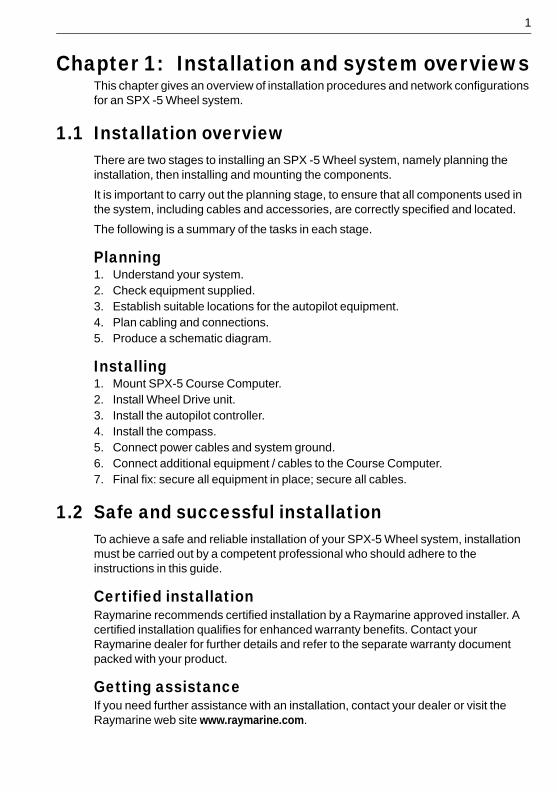
1.1 Installation overviewThere are two stages to installing an SPX -5 Wheel system, namely planning the installation, then installing and mounting the components.
It is important to carry out the planning stage, to ensure that all components used in the system, including cables and accessories, are correctly specified and located.
The following is a summary of the tasks in each stage.
Planning1. Understand your system.2. Check equipment supplied.3. Establish suitable locations for the autopilot equipment.4. Plan cabling and connections.5. Produce a schematic diagram.
Installing1. Mount SPX-5 Course Computer.2. Install Wheel Drive unit.3. Install the autopilot controller.4. Install the compass.5. Connect power cables and system ground.6. Connect additional equipment / cables to the Course Computer.7. Final fix: secure all equipment in place; secure all cables.
1.2 Safe and successful installationTo achieve a safe and reliable installation of your SPX-5 Wheel system, installation must be carried out by a competent professional who should adhere to the instructions in this guide.
Certified installationRaymarine recommends certified installation by a Raymarine approved installer. A certified installation qualifies for enhanced warranty benefits. Contact your Raymarine dealer for further details and refer to the separate warranty document packed with your product.
Getting assistanceIf you need further assistance with an installation, contact your dealer or visit the Raymarine web site www.raymarine.com.
2 SmartPilot X-5 Wheel Installation & Setup Guide
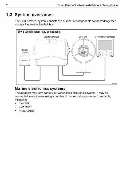
1.3 System overviewsThe SPX-5 Wheel system consists of a number of components connected together using a Raymarine SeaTalk bus.
Marine electronics systemsThe autopilot may form part of your wider ships electronics system. It may be connected to equipment using a number of marine industry standard protocols, including:• SeaTalk.• SeaTalkng
• NMEA 0183
D10501-1
Course Computer
SPX-5 Wheel system - key components
Drive unit
Fluxgatecompass
ST6002 Pilot Controller
Chapter 1: Installation and system overviews 3
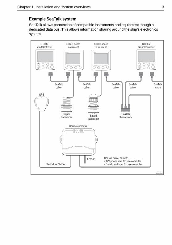
Example SeaTalk systemSeaTalk allows connection of compatible instruments and equipment though a dedicated data bus. This allows information sharing around the ship’s electronics system.
Depthtransducer
GPS
ST60+ depthinstrument
SeaTalkcable
SeaTalkcable
SeaTalk or NMEA
SeaTalkcable
SeaTalkcable
SeaTalk cable, carries:- 12V power from Course computer- Data to and from Course computer
SeaTalkcable
ST60+ speedinstrument
Course computer
ST6002SmartController
Speedtransducer
SeaTalk3-way block
D10628-1
ST6002SmartController
12 V dc
4 SmartPilot X-5 Wheel Installation & Setup Guide
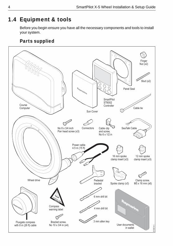
1.4 Equipment & toolsBefore you begin ensure you have all the necessary components and tools to install your system.
Parts supplied
D1
06
14
-1
Clamp screw, M5 x 16 mm (x6)
Wheel drive Pedestalbracket Spoke clamp (x3)
16 mm spokeclamp insert (x3)
12 mm spokeclamp insert (x3)
6 mm drill bit
3 mm allen key
4 mm drill bit
Power cable4.5 m (15 ft)
Bracket screw, No 10 x 3/4 in (x4)
Cable clipand screw,No 6 x 1/2 in
No 8 x 3/4 inchPan head screw (x3)
Sun Cover
SmartPilotST6002Controller
Panel Seal
Cable tie
Connectors
Stud (x2)
FingerNut (x2)
SeaTalk Cable
CourseComputer
Compass warning label
Fluxgate compasswith 8 m (26 ft) cable User documents
in wallet
Chapter 1: Installation and system overviews 5
Tools and equipment NOT suppliedYou will need to supply the following equipment and tools:
Tools:• Cross-head/pozi-drive screwdriver.• Pliers.• Power drill (cordless recommended).• Bearing puller to remove steering wheel.• Tape measure (metric/imperial).• Hammer and center punch.• Pencil, masking tape. • Spanner (Wrench) to fit wheel nut.• Washing-up liquid (to lubricate the spokes).• Hacksaw.• Power/battery Drill. • 4 mm + 6 mm drill bits (supplied).• 3 mm allen key (Hex key, supplied).
Cables / equipment• Power cable and fuse/breaker.• Additional data cables (e.g. for connection of GPS or chartplotter).• Grounding braid.
Optional equipment• Bulkhead fitting kit, Raymarine part number E15017, if your wheel is bulkhead or
box pedestal mounted. • Additional spoke clamp, Raymarine part number A18089. Enables you to fit an
extra clamp to a 4-spoke wheel, for esthetic reasons.
1.5 Create a schematic diagramAs part of the preparation for installing your SPX-5 Wheel system, we recommend that you create a schematic diagram representing the system you want to install. This will help ensure that you install a safe optimum system, and so is particularly important if you intend connecting your autopilot to other electronic equipment.
The schematic diagram should include:• Location of all components. See page v and page 7 for EMC guidelines that may
affect the location of specific components.• Connectors, cable types, routes and lengths.
When you have completed the schematic diagram, you are ready to begin installing the SPX-5 Wheel system.

6 SmartPilot X-5 Wheel Installation & Setup Guide
7
Chapter 2: Installing the systemBefore proceeding with the installation you should have the following to hand:• All necessary equipment and tools to install your SPX-5 Wheel system.• The correct type and length of power cable.• Schematic diagram detailing autopilot system location and connections.
You should also check that existing marine electronics, such as the GPS are installed and working.
2.1 Installation precautions
CAUTION: Switch off power supplySwitch off the power supply before you start installing this product.
EMC installation guidelinesRaymarine equipment and accessories conform to the appropriate Electromagnetic Compatibility (EMC) regulations. This minimizes electromagnetic interference between equipment, which could otherwise affect the performance of your system.
Correct installation is required to ensure that EMC performance is not compromised.
For optimum EMC performance, we recommend that:• Raymarine equipment and the cables connected to it are:
i. At least 3 ft (1 m) from any equipment transmitting or cables carrying radio sig-nals e.g. VHF radios, cables and antennas. In the case of SSB radios, the dis-tance should be increased to 7 ft (2 m).
ii. More than 7 ft (2 m) from the path of a radar beam. A radar beam can normally be assumed to spread 20 degrees above and below the radiating element.
• The product is supplied from a separate battery from that used for engine start. This is important to prevent erratic behavior and data loss which can occur if the engine start does not have a separate battery.
• Raymarine specified cables are used.• Cables are not cut or extended unless doing so is detailed in the installation
manual.
RememberWhere constraints on the installation prevent any of the above recommendations:• Always allow the maximum separation possible between different items of
electrical equipment. This will provide the best conditions for EMC performance for the installation.
WARNING: Install at docksideFor safety reasons your boat must be at dockside before commencing installation.
8 SmartPilot X-5 Wheel Installation & Setup Guide
Suppression ferritesRaymarine cables may be fitted with suppression ferrites. These are important for correct EMC performance. Any ferrite removed to facilitate installation must be replaced in the original position immediately after the installation is complete.
• Use only ferrites of the correct type, supplied by Raymarine authorized dealers.
Connections to other equipmentIf Raymarine equipment is to be connected to other equipment using a cable not supplied by Raymarine, a Raymarine suppression ferrite MUST always be attached to the cable near the Raymarine unit.
CompassThe compass is sensitive to magnetic influences and other potential sources of interference including engines and VHF radio waves. To ensure optimum operation it is essential to locate the compass correctly.
2.2 General cabling guidelines• Do not mix ac and dc cables.• Adhere to EMC guidelines (see page 7).• Use Copex conduit where appropriate to protect cables.• Label all cables for easy identification.• Keep the Fluxgate compass cable separate from other cables.
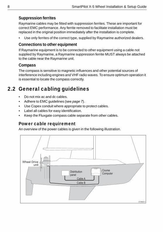
Power cable requirementAn overview of the power cables is given in the following illustration.
D10623-1
Distributionpanel
CourseComputer
Wheel Drive unit
Cable A
Cable B
Chapter 2: Installing the system 9
CAUTION: Power cableUsing an incorrect size of power cable could reduce the power supplied to the drive unit and therefore cause your SPX-5 Wheel system to malfunction. Ensure the correct cable size is used. If in doubt, use a heavier gauge cable.The requirement for power cables depends on the total length of the power circuit. In the above illustration, that is the total length of Cable A + Cable B.
The correct cable dimensions for various cable lengths are given in the following table.
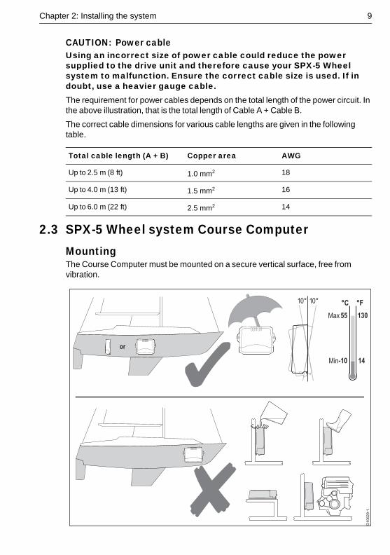
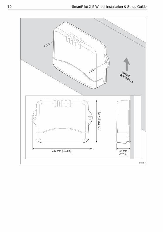
2.3 SPX-5 Wheel system Course ComputerMountingThe Course Computer must be mounted on a secure vertical surface, free from vibration.
Total cable length (A + B) Copper area AWG
Up to 2.5 m (8 ft) 1.0 mm2 18
Up to 4.0 m (13 ft) 1.5 mm2 16
Up to 6.0 m (22 ft) 2.5 mm2 14
or
Min
Max
-10
55
14
130
°F°C10° 10°
D1
06
29
-1
10 SmartPilot X-5 Wheel Installation & Setup Guide
D10375-1
MOUNTVERTICALLY
170
mm
(6.
7 in
)
237 mm (9.33 in) 56 mm(2.2 in)
Chapter 2: Installing the system 11
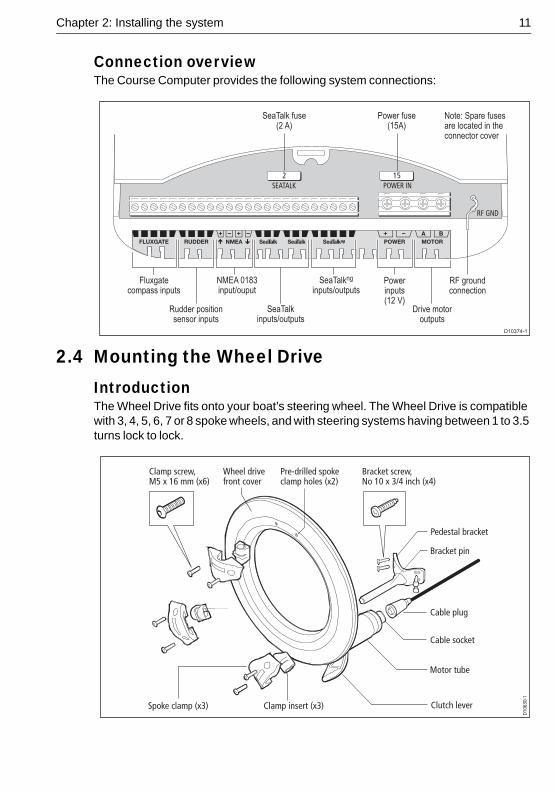
Connection overviewThe Course Computer provides the following system connections:
2.4 Mounting the Wheel DriveIntroductionThe Wheel Drive fits onto your boat’s steering wheel. The Wheel Drive is compatible with 3, 4, 5, 6, 7 or 8 spoke wheels, and with steering systems having between 1 to 3.5 turns lock to lock.
152
A B
Fluxgatecompass inputs
Rudder positionsensor inputs
SeaTalkinputs/outputs
Powerinputs(12 V)
RF groundconnection
NMEA 0183input/ouput
SeaTalkng
inputs/outputs
Drive motoroutputs
D10374-1
SeaTalk fuse(2 A)
Power fuse(15A)
Note: Spare fusesare located in theconnector cover
Clamp screw, M5 x 16 mm (x6)
Wheel drivefront cover
Pre-drilled spokeclamp holes (x2)
Bracket screw, No 10 x 3/4 inch (x4)
Clutch lever
Motor tube
Cable socket
Cable plug
Bracket pin
Pedestal bracketD1
0630
-1
Spoke clamp (x3) Clamp insert (x3)

12 SmartPilot X-5 Wheel Installation & Setup Guide
To install the wheel drive you need to:1. Drill the spoke clamp holes in the front cover.2. Securing the wheel drive to the wheel.3. Attaching the pedestal bracket.
Step 1 –Drill the spoke clamp holes1. Remove the wheel drive front cover:
• The front cover is held onto the wheel drive by three ‘push-fit’ posts which sit in three sockets on the drive ring.
• To remove the cover, hold the motor in one hand and use your other hand to pull the cover up and away from the drive unit (as shown below).
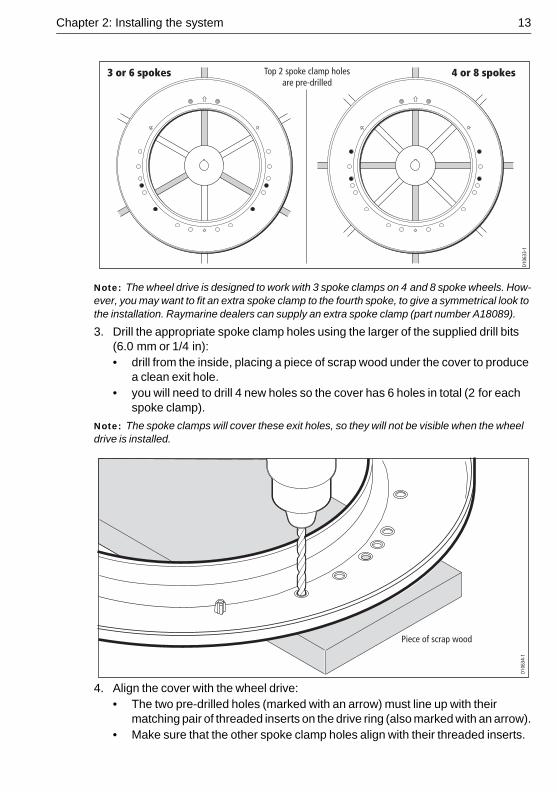
2. Identify the appropriate spoke clamp holes for your wheel. With the arrow at the top, refer to the following diagrams:• The holes are numbered inside the cover (e.g. if you have a 5 spoke wheel,
you need to drill the locations marked with ‘5’).• Mark the appropriate spoke clamp holes and check them by holding the cover
against your wheel.
D106
31-1
D106
32-1
5 spokes 7 spokesTop 2 spoke clamp holesare pre-drilled
Chapter 2: Installing the system 13
Note: The wheel drive is designed to work with 3 spoke clamps on 4 and 8 spoke wheels. How-ever, you may want to fit an extra spoke clamp to the fourth spoke, to give a symmetrical look to the installation. Raymarine dealers can supply an extra spoke clamp (part number A18089).
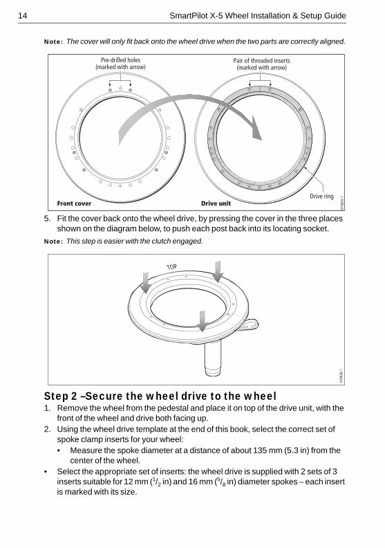
3. Drill the appropriate spoke clamp holes using the larger of the supplied drill bits (6.0 mm or 1/4 in):• drill from the inside, placing a piece of scrap wood under the cover to produce
a clean exit hole.• you will need to drill 4 new holes so the cover has 6 holes in total (2 for each
spoke clamp).
Note: The spoke clamps will cover these exit holes, so they will not be visible when the wheel drive is installed.
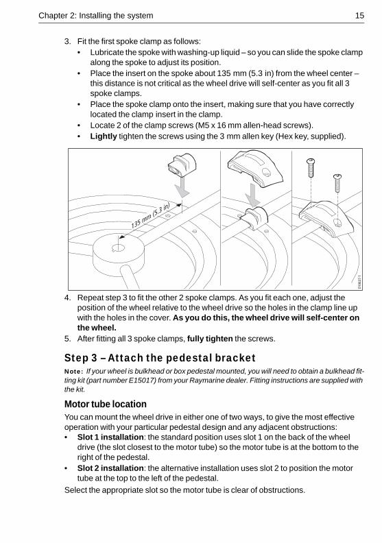
4. Align the cover with the wheel drive:• The two pre-drilled holes (marked with an arrow) must line up with their
matching pair of threaded inserts on the drive ring (also marked with an arrow).• Make sure that the other spoke clamp holes align with their threaded inserts.
D106
33-1
3 or 6 spokes 4 or 8 spokesTop 2 spoke clamp holesare pre-drilled
Piece of scrap wood
D106
34-1
14 SmartPilot X-5 Wheel Installation & Setup Guide
Note: The cover will only fit back onto the wheel drive when the two parts are correctly aligned.
5. Fit the cover back onto the wheel drive, by pressing the cover in the three places shown on the diagram below, to push each post back into its locating socket.
Note: This step is easier with the clutch engaged.
Step 2 –Secure the wheel drive to the wheel1. Remove the wheel from the pedestal and place it on top of the drive unit, with the
front of the wheel and drive both facing up.2. Using the wheel drive template at the end of this book, select the correct set of
spoke clamp inserts for your wheel:• Measure the spoke diameter at a distance of about 135 mm (5.3 in) from the
center of the wheel.• Select the appropriate set of inserts: the wheel drive is supplied with 2 sets of 3
inserts suitable for 12 mm (1/2 in) and 16 mm (5/8 in) diameter spokes – each insert is marked with its size.
Pre-drilled holes(marked with arrow)
Pair of threaded inserts(marked with arrow)
Drive ringFront cover Drive unit
D106
35-1
D106
36-1
TOP
Chapter 2: Installing the system 15
3. Fit the first spoke clamp as follows:• Lubricate the spoke with washing-up liquid – so you can slide the spoke clamp
along the spoke to adjust its position.• Place the insert on the spoke about 135 mm (5.3 in) from the wheel center –
this distance is not critical as the wheel drive will self-center as you fit all 3 spoke clamps.
• Place the spoke clamp onto the insert, making sure that you have correctly located the clamp insert in the clamp.
• Locate 2 of the clamp screws (M5 x 16 mm allen-head screws). • Lightly tighten the screws using the 3 mm allen key (Hex key, supplied).
4. Repeat step 3 to fit the other 2 spoke clamps. As you fit each one, adjust the position of the wheel relative to the wheel drive so the holes in the clamp line up with the holes in the cover. As you do this, the wheel drive will self-center on the wheel.
5. After fitting all 3 spoke clamps, fully tighten the screws.
Step 3 – Attach the pedestal bracketNote: If your wheel is bulkhead or box pedestal mounted, you will need to obtain a bulkhead fit-ting kit (part number E15017) from your Raymarine dealer. Fitting instructions are supplied with the kit.
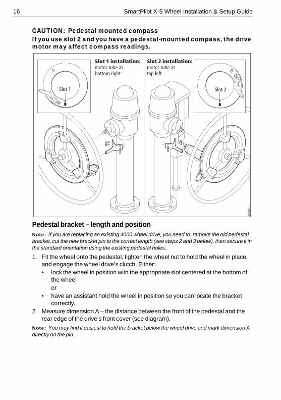
Motor tube locationYou can mount the wheel drive in either one of two ways, to give the most effective operation with your particular pedestal design and any adjacent obstructions:• Slot 1 installation: the standard position uses slot 1 on the back of the wheel
drive (the slot closest to the motor tube) so the motor tube is at the bottom to the right of the pedestal.
• Slot 2 installation: the alternative installation uses slot 2 to position the motor tube at the top to the left of the pedestal.
Select the appropriate slot so the motor tube is clear of obstructions.
D106
37-1
135 mm (5.3 in)
16 SmartPilot X-5 Wheel Installation & Setup Guide
CAUTION: Pedestal mounted compassIf you use slot 2 and you have a pedestal-mounted compass, the drive motor may affect compass readings.
Pedestal bracket – length and positionNote: If you are replacing an existing 4000 wheel drive, you need to: remove the old pedestal bracket, cut the new bracket pin to the correct length (see steps 2 and 3 below), then secure it in the standard orientation using the existing pedestal holes.
1. Fit the wheel onto the pedestal, tighten the wheel nut to hold the wheel in place, and engage the wheel drive’s clutch. Either:• lock the wheel in position with the appropriate slot centered at the bottom of
the wheelor
• have an assistant hold the wheel in position so you can locate the bracket correctly.
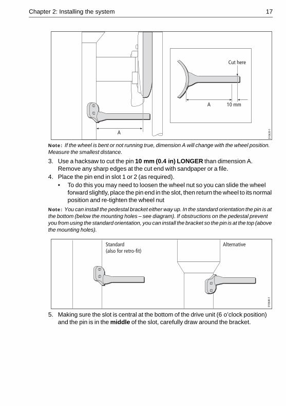
2. Measure dimension A – the distance between the front of the pedestal and the rear edge of the drive’s front cover (see diagram).
Note: You may find it easiest to hold the bracket below the wheel drive and mark dimension A directly on the pin.
D106
38-1
Slot 2 installation:motor tube at top left
Slot 1 installation:motor tube at bottom right
Slot 1 Slot 2
Chapter 2: Installing the system 17
Note: If the wheel is bent or not running true, dimension A will change with the wheel position. Measure the smallest distance.
3. Use a hacksaw to cut the pin 10 mm (0.4 in) LONGER than dimension A. Remove any sharp edges at the cut end with sandpaper or a file.
4. Place the pin end in slot 1 or 2 (as required).• To do this you may need to loosen the wheel nut so you can slide the wheel
forward slightly, place the pin end in the slot, then return the wheel to its normal position and re-tighten the wheel nut
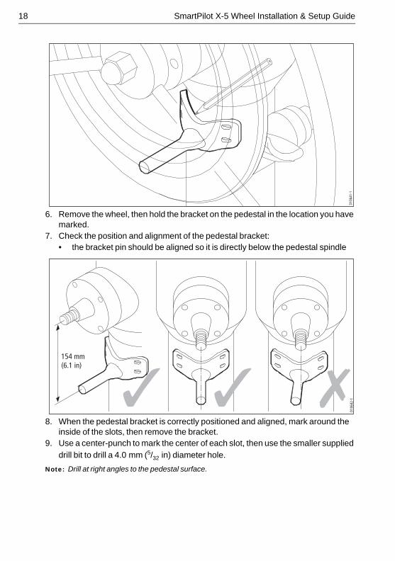
Note: You can install the pedestal bracket either way up. In the standard orientation the pin is at the bottom (below the mounting holes – see diagram). If obstructions on the pedestal prevent you from using the standard orientation, you can install the bracket so the pin is at the top (above the mounting holes).
5. Making sure the slot is central at the bottom of the drive unit (6 o’clock position) and the pin is in the middle of the slot, carefully draw around the bracket.
D106
39-1
A 10 mm
Cut here
A
Standard(also for retro-fit)
Alternative
D106
40-1
18 SmartPilot X-5 Wheel Installation & Setup Guide
6. Remove the wheel, then hold the bracket on the pedestal in the location you have marked.
7. Check the position and alignment of the pedestal bracket:• the bracket pin should be aligned so it is directly below the pedestal spindle
8. When the pedestal bracket is correctly positioned and aligned, mark around the inside of the slots, then remove the bracket.
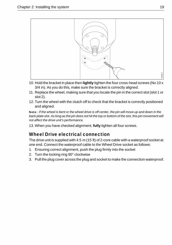
9. Use a center-punch to mark the center of each slot, then use the smaller supplied drill bit to drill a 4.0 mm (5/32 in) diameter hole.
Note: Drill at right angles to the pedestal surface.
D106
41-1
D106
42-1
154 mm(6.1 in)
Chapter 2: Installing the system 19
10. Hold the bracket in place then lightly tighten the four cross-head screws (No 10 x 3/4 in). As you do this, make sure the bracket is correctly aligned.
11. Replace the wheel, making sure that you locate the pin in the correct slot (slot 1 or slot 2).
12. Turn the wheel with the clutch off to check that the bracket is correctly positioned and aligned.
Note: If the wheel is bent or the wheel drive is off center, the pin will move up and down in the back plate slot. As long as the pin does not hit the top or bottom of the slot, this pin movement will not affect the drive unit’s performance.
13. When you have checked alignment, fully tighten all four screws.
Wheel Drive electrical connectionThe drive unit is supplied with 4.5 m (15 ft) of 2-core cable with a waterproof socket at one end. Connect the waterproof cable to the Wheel Drive socket as follows:1. Ensuring correct alignment, push the plug firmly into the socket2. Turn the locking ring 90° clockwise3. Pull the plug cover across the plug and socket to make the connection waterproof.
D106
43-1
20 SmartPilot X-5 Wheel Installation & Setup Guide
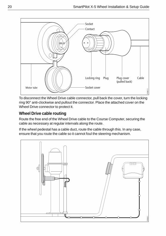
To disconnect the Wheel Drive cable connector, pull back the cover, turn the locking ring 90° anti-clockwise and pullout the connector. Place the attached cover on the Wheel Drive connector to protect it.
Wheel Drive cable routingRoute the free end of the Wheel Drive cable to the Course Computer, securing the cable as necessary at regular intervals along the route.
If the wheel pedestal has a cable duct, route the cable through this. In any case, ensure that you route the cable so it cannot foul the steering mechanism.
D106
17-1
CablePlug cover(pulled back)
Locking ring
Contact
Socket
Socket coverMotor tube
Plug
D106
16-1
Chapter 2: Installing the system 21
2.5 Connecting power & drive cables to the Course ComputerPowerThe SPX-5 Wheel system needs a 12 V dc supply.
CAUTION: Ensure correct supply voltageDo NOT connect 24 V to the Course Computer, or damage to the product could occur.
Circuit breaker/fuseProtect the power supply for the SPX-5 Wheel system with a 10 A fuse or circuit breaker.
CableUsing the information given at Power cable requirement on page 8, obtain the required length of the appropriate cable to connect power from the boat’s distribution panel to the Course Computer.
Connection procedure
A B
D10505-1
Power supply
Red Black
Fuse or circuitbreaker
Distributionpanel
Drive unit
Brown Blue
22 SmartPilot X-5 Wheel Installation & Setup Guide
At the Course Computer, locate the free ends of the cables from the distribution panel and Wheel Drive. Ensuring all power is switched off, refer to the illustration above and connect each cable to the correct Course Computer terminals as follows:1. Strip 8-10 mm (1/2 inch) of insulation from the end of each wire.2. Use a small screwdriver to loosen the relevant screws on the terminal block.3. Insert the stripped wires into the appropriate terminals then tighten the screws.
2.6 Fluxgate CompassUse these instructions to install the Fluxgate Compass.
After fitting the Fluxgate Compass, ensure you affix the compass safe area label adjacent to the Fluxgate Compass.
The compass contains a self-levelling mechanism. This enables the compass to provide accurate readings with pitch and roll movements up to +/- 35°.
Note: When shaken, the Fluxgate Compass makes a rattling sound. This is entirely normal and is not a cause for concern.
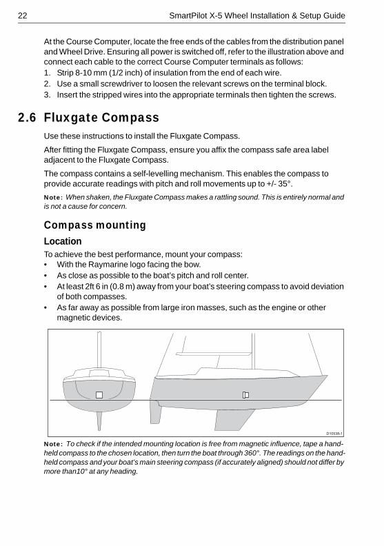
Compass mountingLocationTo achieve the best performance, mount your compass:• With the Raymarine logo facing the bow.• As close as possible to the boat’s pitch and roll center.• At least 2ft 6 in (0.8 m) away from your boat’s steering compass to avoid deviation
of both compasses. • As far away as possible from large iron masses, such as the engine or other
magnetic devices.
Note: To check if the intended mounting location is free from magnetic influence, tape a hand-held compass to the chosen location, then turn the boat through 360°. The readings on the hand-held compass and your boat’s main steering compass (if accurately aligned) should not differ by more than10° at any heading.
D10538-1
Chapter 2: Installing the system 23
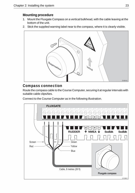
Mounting procedure1. Mount the Fluxgate Compass on a vertical bulkhead, with the cable leaving at the
bottom of the unit. 2. Stick the supplied warning label near to the compass, where it is clearly visible.
Compass connectionRoute the compass cable to the Course Computer, securing it at regular intervals with suitable cable clips/ties.
Connect to the Course Computer as in the following illustration.
D10618-1
Vertical
D10388-1
Cable, 8 metres (26 ft)
Screen
Red
Green
Yellow
Blue
Fluxgate compass
24 SmartPilot X-5 Wheel Installation & Setup Guide
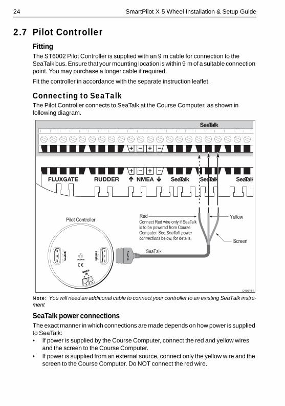
2.7 Pilot ControllerFittingThe ST6002 Pilot Controller is supplied with an 9 m cable for connection to the SeaTalk bus. Ensure that your mounting location is within 9 m of a suitable connection point. You may purchase a longer cable if required.
Fit the controller in accordance with the separate instruction leaflet.
Connecting to SeaTalkThe Pilot Controller connects to SeaTalk at the Course Computer, as shown in following diagram.
:
Note: You will need an additional cable to connect your controller to an existing SeaTalk instru-ment
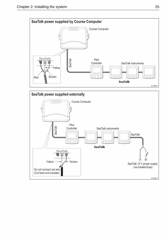
SeaTalk power connectionsThe exact manner in which connections are made depends on how power is supplied to SeaTalk:• If power is supplied by the Course Computer, connect the red and yellow wires
and the screen to the Course Computer.• If power is supplied from an external source, connect only the yellow wire and the
screen to the Course Computer. Do NOT connect the red wire.
D10619-1
Pilot Controller
SeaTalk
Screen
Red YellowConnect Red wire only if SeaTalk is to be powered from Course Computer. See SeaTalk power connections below, for details.
Chapter 2: Installing the system 25
D10644-1
SeaTalk power supplied by Course Computer
Screen
PilotController SeaTalk instruments
SeaTalk
Course Computer
Sea
Tal
kYellow
Red
PilotController SeaTalk instruments
SeaTalk
Course Computer
Sea
Tal
k
SeaTalk
Screen
Do not connect red wire (Cut back and insulate)
YellowSeaTalk 12 V power supply
(via breaker/fuse)
D10645-1
SeaTalk power supplied externally
26 SmartPilot X-5 Wheel Installation & Setup Guide
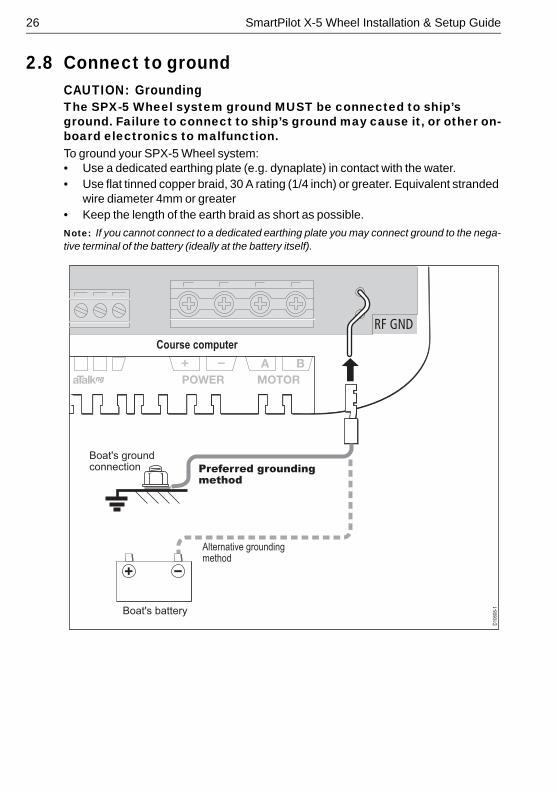
2.8 Connect to groundCAUTION: GroundingThe SPX-5 Wheel system ground MUST be connected to ship’s ground. Failure to connect to ship’s ground may cause it, or other on-board electronics to malfunction.To ground your SPX-5 Wheel system:• Use a dedicated earthing plate (e.g. dynaplate) in contact with the water.• Use flat tinned copper braid, 30 A rating (1/4 inch) or greater. Equivalent stranded
wire diameter 4mm or greater• Keep the length of the earth braid as short as possible.
Note: If you cannot connect to a dedicated earthing plate you may connect ground to the nega-tive terminal of the battery (ideally at the battery itself).
D10
608-
1
Boat's ground connection
Boat's battery
Preferred groundingmethod
Alternative groundingmethod
Course computer
A B
Chapter 2: Installing the system 27
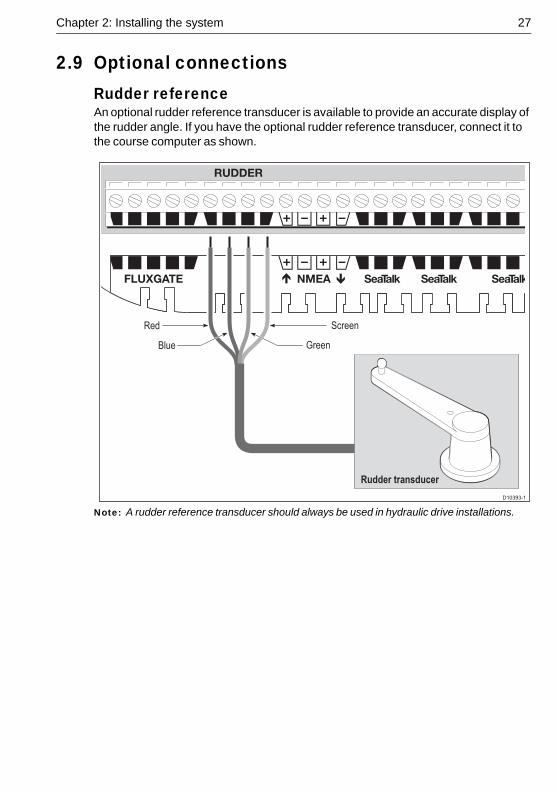
2.9 Optional connectionsRudder referenceAn optional rudder reference transducer is available to provide an accurate display of the rudder angle. If you have the optional rudder reference transducer, connect it to the course computer as shown.
Note: A rudder reference transducer should always be used in hydraulic drive installations.
D10393-1
Rudder transducer
Red
Blue
Screen
Green
28 SmartPilot X-5 Wheel Installation & Setup Guide
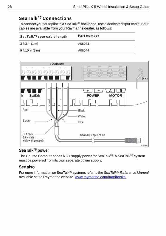
SeaTalkng ConnectionsTo connect your autopilot to a SeaTalkng backbone, use a dedicated spur cable. Spur cables are available from your Raymarine dealer, as follows:
SeaTalkng powerThe Course Computer does NOT supply power for SeaTalkng. A SeaTalkng system must be powered from its own separate power supply.
See alsoFor more information on SeaTalkng systems refer to the SeaTalkng Reference Manual available at the Raymarine website. www.raymarine.com/handbooks.
SeaTalkng spur cable length Part number
3 ft 3 in (1 m) A06043
9 ft 10 in (3 m) A06044
A B
D10394-2
Screen
Red
Cut back& insulateYellow (if present)
Black
White
Blue
SeaTalkng spur cable
Chapter 2: Installing the system 29
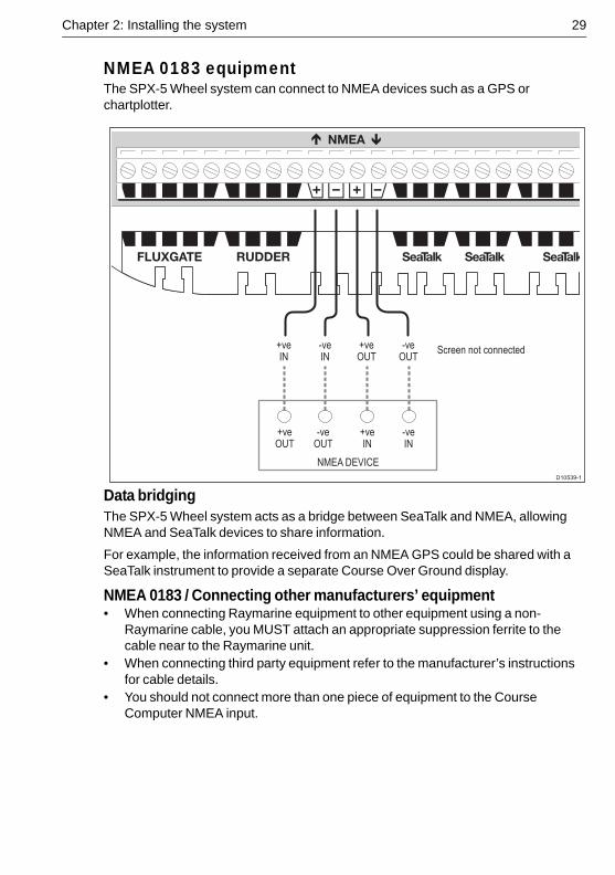
NMEA 0183 equipmentThe SPX-5 Wheel system can connect to NMEA devices such as a GPS or chartplotter.
Data bridgingThe SPX-5 Wheel system acts as a bridge between SeaTalk and NMEA, allowing NMEA and SeaTalk devices to share information.
For example, the information received from an NMEA GPS could be shared with a SeaTalk instrument to provide a separate Course Over Ground display.
NMEA 0183 / Connecting other manufacturers’ equipment• When connecting Raymarine equipment to other equipment using a non-
Raymarine cable, you MUST attach an appropriate suppression ferrite to the cable near to the Raymarine unit.
• When connecting third party equipment refer to the manufacturer’s instructions for cable details.
• You should not connect more than one piece of equipment to the Course Computer NMEA input.
-veIN
+veIN
+veOUT
-veOUT
Screen not connected
NMEA DEVICE
-veOUT
+veOUT
+veIN
-veIN
D10539-1
30 SmartPilot X-5 Wheel Installation & Setup Guide
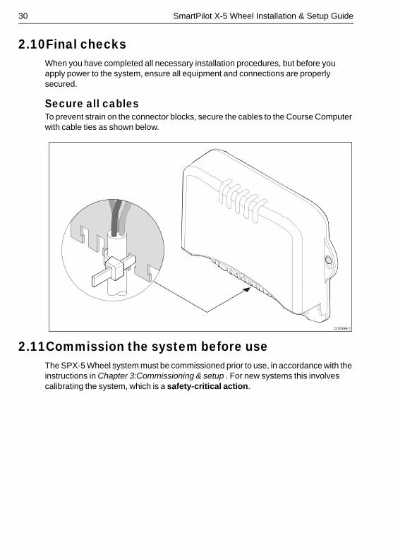
2.10Final checksWhen you have completed all necessary installation procedures, but before you apply power to the system, ensure all equipment and connections are properly secured.
Secure all cablesTo prevent strain on the connector blocks, secure the cables to the Course Computer with cable ties as shown below.
2.11Commission the system before useThe SPX-5 Wheel system must be commissioned prior to use, in accordance with the instructions in Chapter 3:Commissioning & setup . For new systems this involves calibrating the system, which is a safety-critical action.
D10396-1
31
Chapter 3: Commissioning & setupThis chapter describes the commissioning and setup procedures for your Raymarine SPX-5 Wheel system.
RequirementThe commissioning procedures are mandatory and must be carried out after installation, before the SPX-5 Wheel system is used to steer the boat.
Additional setup procedures are also provided for you to fine tune your SPX-5 Wheel system for optimum performance with your boat. They are not mandatory and you may find that you do not need to use them if the SPX-5 Wheel system operates to your satisfaction after commissioning.
When commissioning and setting up the SPX-5 Wheel system, use the supplied ST6002 controller (Pilot Controller):• standby & auto select the required operating mode.• +1, -1, +10 & -10 initiate course changes.• disp & track provide access to extended functions.
Note: The system is also compatible with ST7002, ST8002 and ST70 Pilot Controllers
3.1 CommissioningThe commissioning process comprises:• Dockside checks & setup.• Seatrial calibration.
Dockside checks & setupThe dockside checks comprise:1. Switching on.2. Checking SeaTalk and NMEA 0183 connections.3. Checking autopilot steering sense.4. Setting vessel type and drive type.5. Setting rudder limits, if rudder reference option fitted.
With the boat safely tied up, carry out the dockside checks and setup procedures before any trials at sea or other setup procedures.
Switching on1. Observing the Wheel drive unit, switch on the main power breaker. If the Wheel
drive moves, switch off the power immediately, then ensure the system wiring is correct.
2. When the Pilot Controller and Course Computer are powered up, the controller will beep and show the controller type for a few seconds, before showing the STANDBY screen.A CALIBRATE REQUIRED message may be displayed. This indicates that the autopilot commissioning is not yet complete.
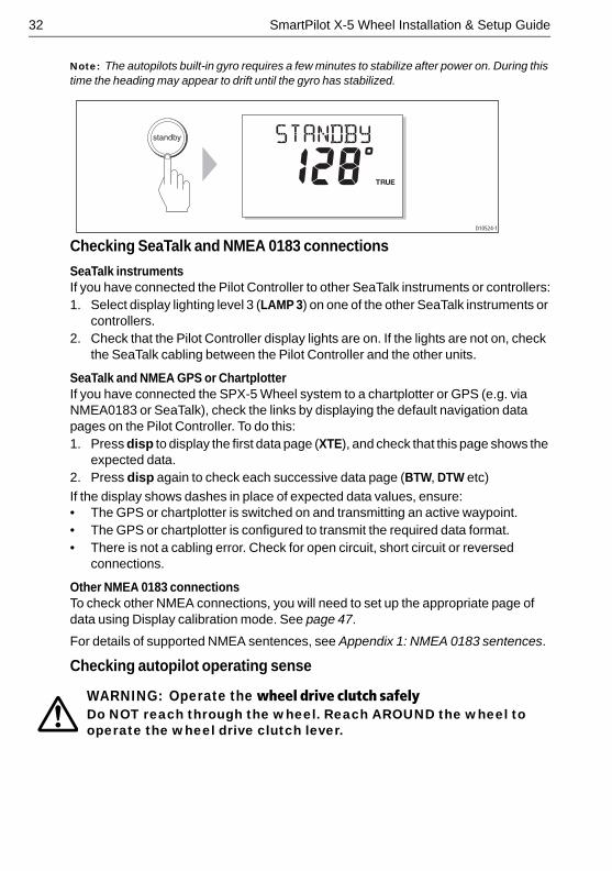
3. Check that the STANDBY screen displays a live compass heading.
32 SmartPilot X-5 Wheel Installation & Setup Guide
Note: The autopilots built-in gyro requires a few minutes to stabilize after power on. During this time the heading may appear to drift until the gyro has stabilized.
Checking SeaTalk and NMEA 0183 connections
SeaTalk instrumentsIf you have connected the Pilot Controller to other SeaTalk instruments or controllers:1. Select display lighting level 3 (LAMP 3) on one of the other SeaTalk instruments or
controllers.2. Check that the Pilot Controller display lights are on. If the lights are not on, check
the SeaTalk cabling between the Pilot Controller and the other units.
SeaTalk and NMEA GPS or ChartplotterIf you have connected the SPX-5 Wheel system to a chartplotter or GPS (e.g. via NMEA0183 or SeaTalk), check the links by displaying the default navigation data pages on the Pilot Controller. To do this:1. Press disp to display the first data page (XTE), and check that this page shows the
expected data.2. Press disp again to check each successive data page (BTW, DTW etc)
If the display shows dashes in place of expected data values, ensure:• The GPS or chartplotter is switched on and transmitting an active waypoint.• The GPS or chartplotter is configured to transmit the required data format.• There is not a cabling error. Check for open circuit, short circuit or reversed
connections.
Other NMEA 0183 connectionsTo check other NMEA connections, you will need to set up the appropriate page of data using Display calibration mode. See page 47.
For details of supported NMEA sentences, see Appendix 1: NMEA 0183 sentences.
Checking autopilot operating sense
WARNING: Operate the wheel drive clutch safelyDo NOT reach through the wheel. Reach AROUND the wheel to operate the wheel drive clutch lever.
D10524-1
TRUE
Chapter 3: Commissioning & setup 33
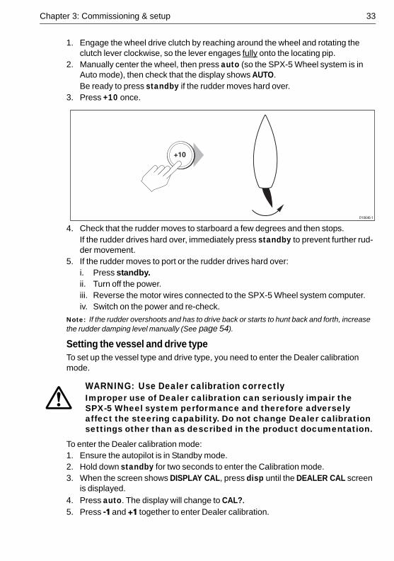
1. Engage the wheel drive clutch by reaching around the wheel and rotating the clutch lever clockwise, so the lever engages fully onto the locating pip.
2. Manually center the wheel, then press auto (so the SPX-5 Wheel system is in Auto mode), then check that the display shows AUTO.Be ready to press standby if the rudder moves hard over.
3. Press +10 once. .
4. Check that the rudder moves to starboard a few degrees and then stops.If the rudder drives hard over, immediately press standby to prevent further rud-der movement.
5. If the rudder moves to port or the rudder drives hard over:i. Press standby.ii. Turn off the power.iii. Reverse the motor wires connected to the SPX-5 Wheel system computer.iv. Switch on the power and re-check.
Note: If the rudder overshoots and has to drive back or starts to hunt back and forth, increase the rudder damping level manually (See page 54).
Setting the vessel and drive typeTo set up the vessel type and drive type, you need to enter the Dealer calibration mode.
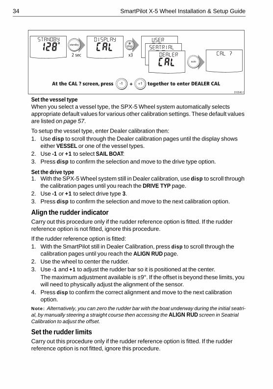
To enter the Dealer calibration mode:1. Ensure the autopilot is in Standby mode.2. Hold down standby for two seconds to enter the Calibration mode.3. When the screen shows DISPLAY CAL, press disp until the DEALER CAL screen
is displayed.
4. Press auto. The display will change to CAL?.5. Press -1 and +1 together to enter Dealer calibration.
WARNING: Use Dealer calibration correctlyImproper use of Dealer calibration can seriously impair the SPX-5 Wheel system performance and therefore adversely affect the steering capability. Do not change Dealer calibration settings other than as described in the product documentation.
D10646-1
34 SmartPilot X-5 Wheel Installation & Setup Guide
Set the vessel typeWhen you select a vessel type, the SPX-5 Wheel system automatically selects appropriate default values for various other calibration settings. These default values are listed on page 57.
To setup the vessel type, enter Dealer calibration then:1. Use disp to scroll through the Dealer calibration pages until the display shows
either VESSEL or one of the vessel types.2. Use -1 or +1 to select SAIL BOAT:3. Press disp to confirm the selection and move to the drive type option.
Set the drive type1. With the SPX-5 Wheel system still in Dealer calibration, use disp to scroll through
the calibration pages until you reach the DRIVE TYP page.2. Use -1 or +1 to select drive type 3.3. Press disp to confirm the selection and move to the next calibration option.
Align the rudder indicatorCarry out this procedure only if the rudder reference option is fitted. If the rudder reference option is not fitted, ignore this procedure.
If the rudder reference option is fitted: 1. With the SmartPilot still in Dealer Calibration, press disp to scroll through the
calibration pages until you reach the ALIGN RUD page.2. Use the wheel to center the rudder.3. Use -1 and +1 to adjust the rudder bar so it is positioned at the center.
The maximum adjustment available is ±9°. If the offset is beyond these limits, you will need to physically adjust the alignment of the sensor.
4. Press disp to confirm the correct alignment and move to the next calibration option.
Note: Alternatively, you can zero the rudder bar with the boat underway during the initial seatri-al, by manually steering a straight course then accessing the ALIGN RUD screen in Seatrial Calibration to adjust the offset.
Set the rudder limitsCarry out this procedure only if the rudder reference option is fitted. If the rudder reference option is not fitted, ignore this procedure.
At the CAL ? screen, press + together to enter DEALER CAL
2 sec x3
-1 +1
D10540-1
Chapter 3: Commissioning & setup 35
If the rudder reference option is fitted: 1. With the SmartPilot still in Dealer Calibration press disp to scroll through the
calibration pages until you reach the RUD LIMIT page.2. Turn the wheel to move the rudder:
• To the port end stop and note the angle on the rudder bar• To the starboard end stop and note the angle on the rudder bar
3. Use -1, +1, -10 and +10 to set the rudder limit to 5° less than the lowest angle you have noted.
4. Press disp to select the new value and move to the next calibration option.
Save the new settingsWhen you have adjusted the above settings, hold down standby for two seconds, to save your changes, leave Dealer calibration and return to the Standby mode.
Seatrial calibrationWhen you have completed the dockside checks, carry out a Seatrial calibration, to calibrate the compass and set up the autopilot steering characteristics.
Before commencing the seatrial:• The dockside calibration must have been successfully completed.• There must be no EMC problems (see page 7).
ImportantIf you need to return to manual steering at any time during a Seatrial or any other procedure, press the standby button. NEVER compromise vessel safety.
Seatrial conditionsThe seatrial must be carried out only:• In conditions of light wind and calm water.• In waters that are clear of any obstructions, so the boat has plenty of clear space
to maneuver.
In order to achieve optimum autopilot performance, course over ground (COG), speed over ground (SOG) and latitude (LAT) data must be available to the SPX-5 Wheel system (e.g. on SeaTalk). Ensure that the equipment providing this information (e.g. GPS), is switched on and fully operational, before starting a Seatrial.
The Seatrial procedures are:• Compass calibration.• Using AutoLearn to set the SPX-5 Wheel system steering characteristics.
Compass calibrationThe compass calibration procedures are:• Swinging the compass.• Aligning the compass.
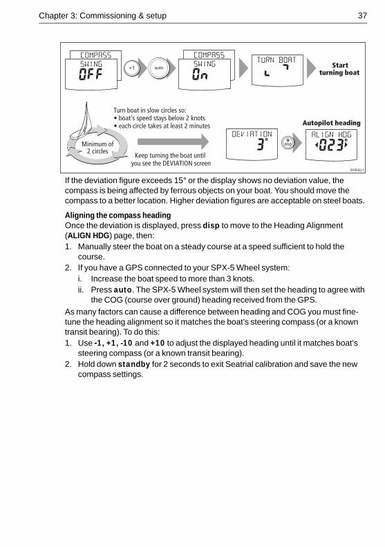
Swinging the compassThe magnetic deviation correction procedure (commonly called “swinging the compass”) involves turning your boat in slow circles so the autopilot can automatically
36 SmartPilot X-5 Wheel Installation & Setup Guide
determine the deviation and apply any correction required. The correction procedure reduces deviation errors to a few degrees.
As magnetic deviation can cause significant compass errors on your boat, you MUST complete the compass swing before any other seatrial procedure.
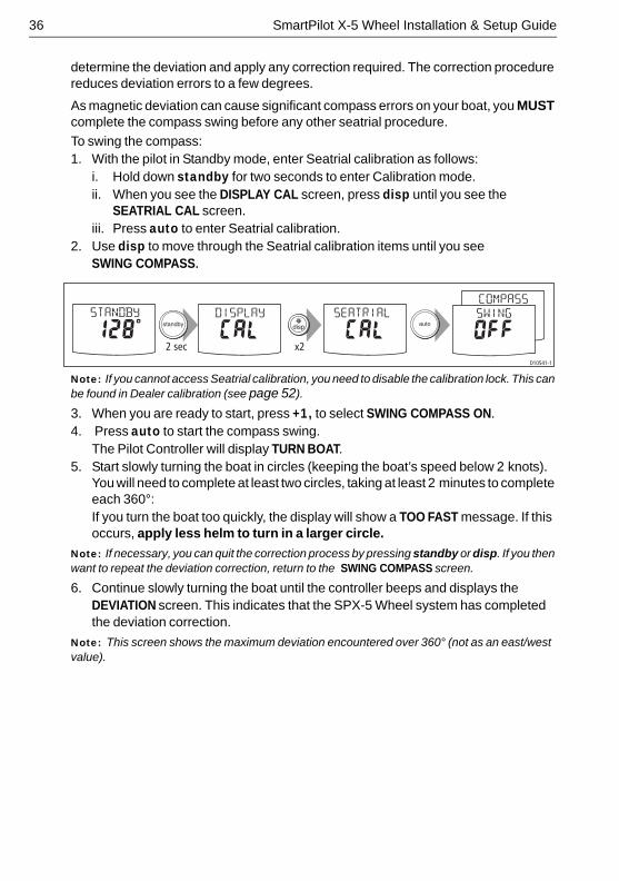
To swing the compass:1. With the pilot in Standby mode, enter Seatrial calibration as follows:
i. Hold down standby for two seconds to enter Calibration mode.ii. When you see the DISPLAY CAL screen, press disp until you see the
SEATRIAL CAL screen.iii. Press auto to enter Seatrial calibration.
2. Use disp to move through the Seatrial calibration items until you see SWING COMPASS.
Note: If you cannot access Seatrial calibration, you need to disable the calibration lock. This can be found in Dealer calibration (see page 52).
3. When you are ready to start, press +1, to select SWING COMPASS ON.4. Press auto to start the compass swing.
The Pilot Controller will display TURN BOAT. 5. Start slowly turning the boat in circles (keeping the boat’s speed below 2 knots).
You will need to complete at least two circles, taking at least 2 minutes to complete each 360°:If you turn the boat too quickly, the display will show a TOO FAST message. If this occurs, apply less helm to turn in a larger circle.
Note: If necessary, you can quit the correction process by pressing standby or disp. If you then want to repeat the deviation correction, return to the SWING COMPASS screen.
6. Continue slowly turning the boat until the controller beeps and displays the DEVIATION screen. This indicates that the SPX-5 Wheel system has completed the deviation correction.
Note: This screen shows the maximum deviation encountered over 360° (not as an east/west value).
2 sec x2D10541-1
Chapter 3: Commissioning & setup 37
If the deviation figure exceeds 15° or the display shows no deviation value, the compass is being affected by ferrous objects on your boat. You should move the compass to a better location. Higher deviation figures are acceptable on steel boats.
Aligning the compass headingOnce the deviation is displayed, press disp to move to the Heading Alignment (ALIGN HDG) page, then:1. Manually steer the boat on a steady course at a speed sufficient to hold the
course. 2. If you have a GPS connected to your SPX-5 Wheel system:
i. Increase the boat speed to more than 3 knots.ii. Press auto. The SPX-5 Wheel system will then set the heading to agree with
the COG (course over ground) heading received from the GPS.
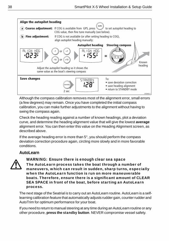
As many factors can cause a difference between heading and COG you must fine-tune the heading alignment so it matches the boat’s steering compass (or a known transit bearing). To do this:1. Use -1, +1, -10 and +10 to adjust the displayed heading until it matches boat’s
steering compass (or a known transit bearing).2. Hold down standby for 2 seconds to exit Seatrial calibration and save the new
compass settings.
D10542-1
Turn boat in slow circles so:• boat's speed stays below 2 knots• each circle takes at least 2 minutes
Minimum of2 circles
Keep turning the boat until you see the DEVIATION screen
Startturning boat
Autopilot heading
38 SmartPilot X-5 Wheel Installation & Setup Guide
Although the compass calibration removes most of the alignment error, small errors (a few degrees) may remain. Once you have completed the initial compass calibration, you can make further adjustments to the alignment without having to swing the compass again.
Check the heading reading against a number of known headings, plot a deviation curve, and determine the heading alignment value that will give the lowest average alignment error. You can then enter this value on the Heading Alignment screen, as described above.
If the average heading error is more than 5°, you should perform the compass deviation correction procedure again, circling more slowly and in more favorable conditions.
AutoLearn
The next stage of the Seatrial is to carry out an AutoLearn routine. AutoLearn is a self-learning calibration feature that automatically adjusts rudder gain, counter rudder and AutoTrim for optimum performance for your boat.
If you need to return to manual steering at any time during an AutoLearn routine or any other procedure, press the standby button. NEVER compromise vessel safety.
WARNING: Ensure there is enough clear sea spaceThe AutoLearn process takes the boat through a number of maneuvers, which can result in sudden, sharp turns, especially when the AutoLearn function is run on more maneuverable boats. Therefore, ensure there is a significant amount of CLEAR SEA SPACE in front of the boat, before starting an AutoLearn process.
2 secD10543-1
Align the autopilot heading
a
b
Save changes To:• save deviation correction• save heading alignment• return to STANDBY mode
Autopilot heading Steering compass
=Knownheading
or
or
Adjust the autopilot heading so it shows thesame value as the boat's steering compass
Coarse adjustment: If COG is available from GPS, press to set autopilot heading to COG value, then fine tune manually (see below).
Fine adjustment: If COG is not available (or after setting heading to COG), align autopilot heading manually:
Chapter 3: Commissioning & setup 39
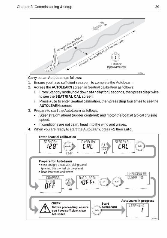
Carry out an AutoLearn as follows:1. Ensure you have sufficient sea room to complete the AutoLearn:2. Access the AUTOLEARN screen in Seatrial calibration as follows:
i. From Standby mode, hold down standby for 2 seconds, then press disp twice to see the SEATRIAL CAL screen.
ii. Press auto to enter Seatrial calibration, then press disp four times to see the AUTOLEARN screen.
3. Prepare to start the AutoLearn as follows: • Steer straight ahead (rudder centered) and motor the boat at typical cruising
speed.• If conditions are not calm, head into the wind and waves.
4. When you are ready to start the AutoLearn, press +1 then auto.
At least 0
.25 nm (500 m) of clear se
a space
At least 0
.04 nm (100 m)
of clear se
a space
D10544-1
1 minute(approximately)
Wind
2 sec x2
• steer straight ahead at cruising speed (planing boats – just on the plane)• head into wind and waves
x4
D10545-1
AutoLearn in progress
Prepare for AutoLearn
Start AutoLearn
Enter Seatrial calibration
CHECK!Before proceeding, ensure you have sufficient clear sea space
40 SmartPilot X-5 Wheel Installation & Setup Guide
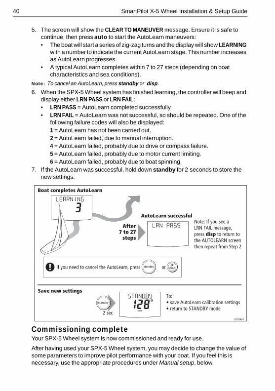
5. The screen will show the CLEAR TO MANEUVER message. Ensure it is safe to continue, then press auto to start the AutoLearn maneuvers:• The boat will start a series of zig-zag turns and the display will show LEARNING
with a number to indicate the current AutoLearn stage. This number increases as AutoLearn progresses.
• A typical AutoLearn completes within 7 to 27 steps (depending on boat characteristics and sea conditions).
Note: To cancel an AutoLearn, press standby or disp.
6. When the SPX-5 Wheel system has finished learning, the controller will beep and display either LRN PASS or LRN FAIL: • LRN PASS = AutoLearn completed successfully• LRN FAIL = AutoLearn was not successful, so should be repeated. One of the
following failure codes will also be displayed:1 = AutoLearn has not been carried out. 2 = AutoLearn failed, due to manual interruption. 4 = AutoLearn failed, probably due to drive or compass failure.5 = AutoLearn failed, probably due to motor current limiting.6 = AutoLearn failed, probably due to boat spinning.
7. If the AutoLearn was successful, hold down standby for 2 seconds to store the new settings.
Commissioning completeYour SPX-5 Wheel system is now commissioned and ready for use.
After having used your SPX-5 Wheel system, you may decide to change the value of some parameters to improve pilot performance with your boat. If you feel this is necessary, use the appropriate procedures under Manual setup, below.
2 secD10546-1
AutoLearn successful
If you need to cancel the AutoLearn, press or
Note: If you see a LRN FAIL message, press disp to return to the AUTOLEARN screen then repeat from Step 2
After7 to 27
steps
!
Boat completes AutoLearn
Save new settingsTo:• save AutoLearn calibration settings• return to STANDBY mode
Chapter 3: Commissioning & setup 41
3.2 Manual setupChecking SPX-5 Wheel system operationBefore manually adjusting any settings, familiarize yourself with basic SPX-5 Wheel system operation, as follows:1. Steer onto a compass heading and hold the course steady at a normal cruising
speed. If necessary, steer the boat manually for a short time to check how the boat steers.
2. Press auto to lock onto the current heading. The SPX-5 Wheel system should hold the locked heading in calm sea conditions.
3. Use -1, +1, -10 and +10 and observe how the SPX-5 Wheel system alters the course to port and starboard.
4. Press standby to return to manual steering.
If you feel you need to fine tune the SPX-5 Wheel system performance, you can do so by using one or more of the procedures below to adjust:• Response level.• Rudder gain.• Counter rudder.• AutoTrim.
Over time you may wish to repeat these adjustments using a range of sea conditions and headings to achieve optimum all-round performance for your particular vessel and preferences.
Adjust these settings when motoring your boat at cruising speed.
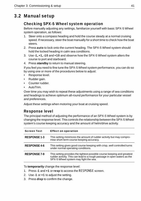
Response levelThe principal method of adjusting the performance of an SPX-5 Wheel system is by changing the response level. This controls the relationship between the SPX-5 Wheel system’s course keeping accuracy and the amount of helm/drive activity.
To temporarily change the response level:
1. Press -1 and +1 or resp to access the RESPONSE screen.2. Use -1 or +1 to adjust the setting.3. Press disp to confirm the change.
Screen Text Effect on operation
RESPONSE 1-3 This setting minimizes the amount of rudder activity but may compro-mise short-term course keeping accuracy,
RESPONSE 4-6 This setting gives good course keeping with crisp, well controlled turns under normal operating conditions.
RESPONSE 7-9 This setting provides the tightest possible course keeping and greatest rudder activity. This can lead to a rough passage in open waters as the SPX-5 Wheel system may fight the sea.
42 SmartPilot X-5 Wheel Installation & Setup Guide
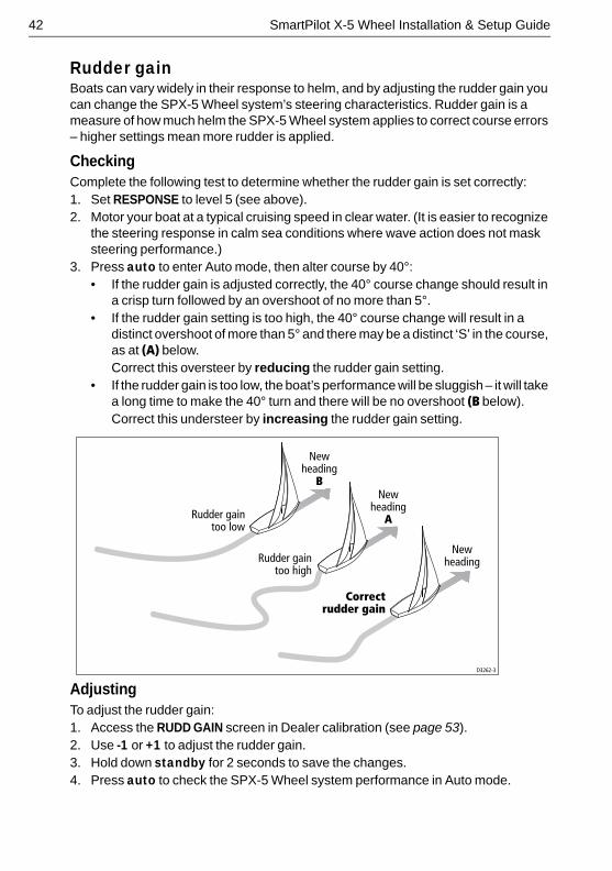
Rudder gainBoats can vary widely in their response to helm, and by adjusting the rudder gain you can change the SPX-5 Wheel system’s steering characteristics. Rudder gain is a measure of how much helm the SPX-5 Wheel system applies to correct course errors – higher settings mean more rudder is applied.
CheckingComplete the following test to determine whether the rudder gain is set correctly:1. Set RESPONSE to level 5 (see above).2. Motor your boat at a typical cruising speed in clear water. (It is easier to recognize
the steering response in calm sea conditions where wave action does not mask steering performance.)
3. Press auto to enter Auto mode, then alter course by 40°:• If the rudder gain is adjusted correctly, the 40° course change should result in
a crisp turn followed by an overshoot of no more than 5°.• If the rudder gain setting is too high, the 40° course change will result in a
distinct overshoot of more than 5° and there may be a distinct ‘S’ in the course, as at (A) below.Correct this oversteer by reducing the rudder gain setting.
• If the rudder gain is too low, the boat’s performance will be sluggish – it will take a long time to make the 40° turn and there will be no overshoot (B below).Correct this understeer by increasing the rudder gain setting.
AdjustingTo adjust the rudder gain:1. Access the RUDD GAIN screen in Dealer calibration (see page 53).2. Use -1 or +1 to adjust the rudder gain. 3. Hold down standby for 2 seconds to save the changes.4. Press auto to check the SPX-5 Wheel system performance in Auto mode.
Newheading
Newheading
A
Newheading
B
Correctrudder gain
Rudder gaintoo high
Rudder gaintoo low
D3262-3
Chapter 3: Commissioning & setup 43
Counter rudder Counter rudder is the amount of rudder the SPX-5 Wheel system applies to try to prevent the boat from yawing off course. Higher counter rudder settings result in more rudder being applied.
CheckingTo check the counter rudder setting:1. Set RESPONSE to level 5 (see page 41).2. Motor your boat at cruising speed in clear water.3. Press auto to switch the SPX-5 Wheel system to Auto mode, then make a 90°
course change:• When gain and counter rudder are both set correctly, the boat performs a
smooth continuous turn with minimal overshoot.• If the counter rudder is too low, the boat will still overshoot.• If counter rudder is too high, the boat will ‘fight the turn’ and make a series of
short, sharp turns: this results in a very ‘mechanical’ feel as the boat changes course.
AdjustingTo adjust the counter rudder:1. Access the COUNT RUD screen in Dealer calibration. (see page 53)2. Use -1 or +1 to adjust the counter rudder. 3. Press and hold standby for 2 seconds to save the changes.4. Press auto to check the SPX-5 Wheel system performance in Auto mode.
AutoTrimYou may also wish to adjust the AutoTrim setting. AutoTrim determines how quickly the SPX-5 Wheel system applies ‘standing helm’ to correct for trim changes, caused, for example, by changes in the wind load on the superstructure, or an imbalance of engines.
Increasing the AutoTrim level reduces the time the SPX-5 Wheel system takes to get back onto the correct course, but makes the boat less stable. If the SPX-5 Wheel system:• Gives unstable course keeping and the boat ‘snakes’ around the desired course,
decrease the AutoTrim level.• Hangs off course for excessive periods of time, increase the AutoTrim level.
AdjustingBefore attempting to adjust the AutoTrim setting, ensure you have sufficient experience using your SPX-5 Wheel system.
If you need to adjust AutoTrim, go up one level at a time and use the lowest acceptable value. The range of settings is from OFF (no trim correction) to 4 (fastest trim correction).
44 SmartPilot X-5 Wheel Installation & Setup Guide
To adjust the AutoTrim1. Access the AUTOTRIM screen in Dealer calibration.mode, then:2. Use -1 or +1 to adjust the AutoTrim level. 3. Hold down standby for 2 seconds to save the changes. 4. Press auto to check the SPX-5 Wheel system performance in Auto mode.
45
Chapter 4: SPX-5 Wheel system settings4.1 Introduction
This chapter describes the SPX-5 Wheel system calibration settings and the factory default settings. The calibration settings can be adjusted to best suit your operating requirements, but as many will have been adjusted to optimum values when commissioning the system, they should not require further change.
If you change the calibration settings after the SPX-5 Wheel system has been commissioned, you do not need to repeat the commissioning process. However, DO NOT manually adjust autopilot settings before the commissioning procedures in Chapter 3 have been completed.
Calibration modesThere are four calibration modes, namely Display calibration, User calibration, Seatrial calibration and Dealer calibration.
Each calibration mode uses a series of screens to set calibration values.
Display calibrationThe items in Display calibration affect the SPX-5 Wheel system Pilot Controller. They are stored in the controller and do not affect any other controllers connected through SeaTalk.
You can adjust the Display calibration settings as often as necessary – for example, to add or change information displayed on data pages.
User calibrationThe User calibration mode includes settings that you may need to adjust on a regular basis to respond to changing conditions.
Seatrial calibrationThe Seatrial calibration mode is used ONLY when commissioning your SPX-5 Wheel system, as described in Chapter 3, so is not described again here. Do not access Seatrial calibration during normal operation.
Dealer calibrationThe Dealer calibration mode includes items that have a significant impact on operation and can affect your boat’s safety.
After you have completed the initial installation and seatrial, you should not normally need to alter the Dealer calibration values.
46 SmartPilot X-5 Wheel Installation & Setup Guide
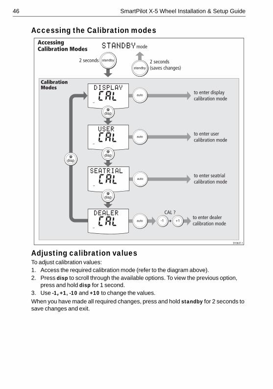
Accessing the Calibration modes
Adjusting calibration valuesTo adjust calibration values:1. Access the required calibration mode (refer to the diagram above).2. Press disp to scroll through the available options. To view the previous option,
press and hold disp for 1 second.3. Use -1, +1, -10 and +10 to change the values.
When you have made all required changes, press and hold standby for 2 seconds to save changes and exit.
+
AccessingCalibration Modes
2 seconds 2 seconds(saves changes)
CalibrationModes
to enter seatrialcalibration mode
D10647-1
to enter dealercalibration mode
to enter displaycalibration mode
to enter usercalibration mode
CAL ?
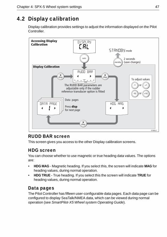
Chapter 4: SPX-5 Wheel system settings 47
4.2 Display calibrationDisplay calibration provides settings to adjust the information displayed on the Pilot Controller.
RUDD BAR screenThis screen gives you access to the other Display calibration screens.
HDG screenYou can choose whether to use magnetic or true heading data values. The options are:
• HDG MAG - Magnetic heading. If you select this, the screen will indicate MAG for heading values, during normal operation.
• HDG TRUE - True heading. If you select this the screen will indicate TRUE for heading values, during normal operation.
Data pages The Pilot Controller has fifteen user-configurable data pages. Each data page can be configured to display SeaTalk/NMEA data, which can be viewed during normal operation (see SmartPilot-X5 Wheel system Operating Guide).
D10602-1
or
or
To adjust values
2 seconds(save changes)
Data pages
Press dispfor next page
Accessing DisplayCalibration
Display Calibration
The RUDD BAR parameters are adjustable only if the rudder
reference transducer option is fitted
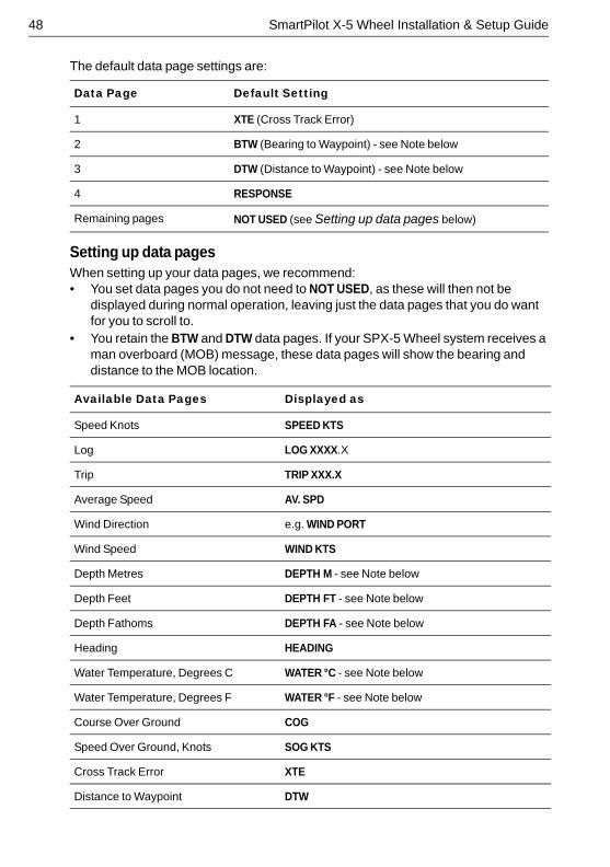
48 SmartPilot X-5 Wheel Installation & Setup Guide
The default data page settings are:
Setting up data pagesWhen setting up your data pages, we recommend:• You set data pages you do not need to NOT USED, as these will then not be
displayed during normal operation, leaving just the data pages that you do want for you to scroll to.
• You retain the BTW and DTW data pages. If your SPX-5 Wheel system receives a man overboard (MOB) message, these data pages will show the bearing and distance to the MOB location.
.
Data Page Default Setting
1 XTE (Cross Track Error)
2 BTW (Bearing to Waypoint) - see Note below
3 DTW (Distance to Waypoint) - see Note below
4 RESPONSE
Remaining pages NOT USED (see Setting up data pages below)
Available Data Pages Displayed as
Speed Knots SPEED KTS
Log LOG XXXX.X
Trip TRIP XXX.X
Average Speed AV. SPD
Wind Direction e.g. WIND PORT
Wind Speed WIND KTS
Depth Metres DEPTH M - see Note below
Depth Feet DEPTH FT - see Note below
Depth Fathoms DEPTH FA - see Note below
Heading HEADING
Water Temperature, Degrees C WATER °C - see Note below
Water Temperature, Degrees F WATER °F - see Note below
Course Over Ground COG
Speed Over Ground, Knots SOG KTS
Cross Track Error XTE
Distance to Waypoint DTW
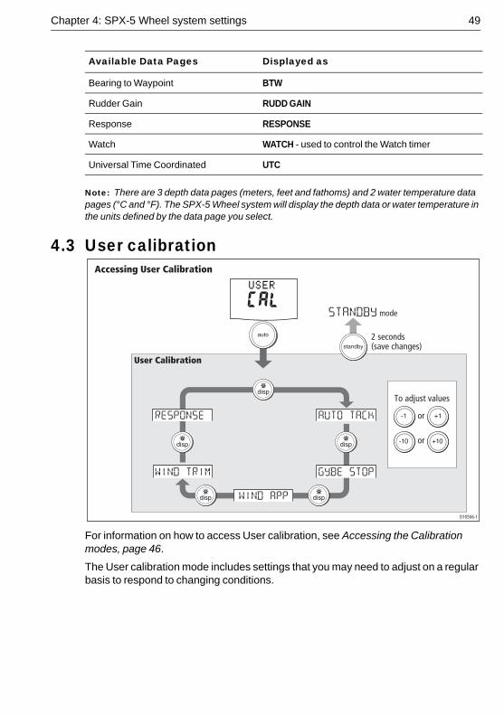
Chapter 4: SPX-5 Wheel system settings 49
Note: There are 3 depth data pages (meters, feet and fathoms) and 2 water temperature data pages (°C and °F). The SPX-5 Wheel system will display the depth data or water temperature in the units defined by the data page you select.
4.3 User calibration
For information on how to access User calibration, see Accessing the Calibration modes, page 46.
The User calibration mode includes settings that you may need to adjust on a regular basis to respond to changing conditions.
Bearing to Waypoint BTW
Rudder Gain RUDD GAIN
Response RESPONSE
Watch WATCH - used to control the Watch timer
Universal Time Coordinated UTC
Available Data Pages Displayed as
D10506-1
or
or
To adjust values
2 seconds(save changes)
Accessing User Calibration
User Calibration
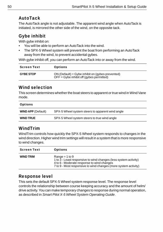
50 SmartPilot X-5 Wheel Installation & Setup Guide
AutoTackThe AutoTack angle is not adjustable. The apparent wind angle when AutoTack is initiated, is mirrored the other side of the wind, on the opposite tack.
Gybe inhibitWith gybe inhibit on:• You will be able to perform an AutoTack into the wind.• The SPX-5 Wheel system will prevent the boat from performing an AutoTack
away from the wind, to prevent accidental gybes.
With gybe inhibit off, you can perform an AutoTack into or away from the wind.
Wind selectionThis screen determines whether the boat steers to apparent or true wind in Wind Vane mode.
WindTrimWindTrim controls how quickly the SPX-5 Wheel system responds to changes in the wind direction. Higher wind trim settings will result in a system that is more responsive to wind changes.
Response levelThis sets the default SPX-5 Wheel system response level. The response level controls the relationship between course keeping accuracy and the amount of helm/drive activity. You can make temporary changes to response during normal operation, as described in Smart Pilot X-5 Wheel System Operating Guide.
Screen Text Options
GYBE STOP ON (Default) = Gybe inhibit on (gybes prevented)OFF = Gybe inhibit off (gybes permitted)
Options
WIND APP (Default) SPX-5 Wheel system steers to apparent wind angle
WIND TRUE SPX-5 Wheel system steers to true wind angle
Screen Text Options
WIND TRIM Range = 1 to 9 1 to 3 - Least responsive to wind changes (less system activity)4 to 6 - Moderate response to wind changes7 to 9 - Most responsive to wind changes (more system activity)
Chapter 4: SPX-5 Wheel system settings 51
4.4 Dealer calibration For information on how to access Dealer calibration, see Accessing the Calibration modes, page 46.
Some Dealer calibration values are adjusted during the commissioning process (see Chapter 2: Commissioning & setup), and once the SPX-5 Wheel system has been commissioned you should not normally need to change Dealer calibration values.
However if you decide you want to change values in Dealer calibration, be aware that the Dealer calibration mode includes items that have a significant impact on SPX-5 Wheel system operation and can affect your boat’s safety.
Screen Text Options
RESPONSE Range = 1 to 9 Level 1 to 3 minimizes the amount of pilot activity. This conserves power, but may compromise short-term course-keeping accuracy.Level 4 to 6 should give good course keeping with crisp, well con-trolled turns under normal operating conditionsLevel 7 to 9 gives the tightest course keeping and greatest rudder activity (and power consumption). This can lead to a rough passage in open waters as the SPX-5 Wheel system may ‘fight’ the sea.
WARNING: Dealer calibrationChanging the Dealer calibration values can have a significant affect on the SPX-5 Wheel system steering characteristics and therefore on the safety of your boat.
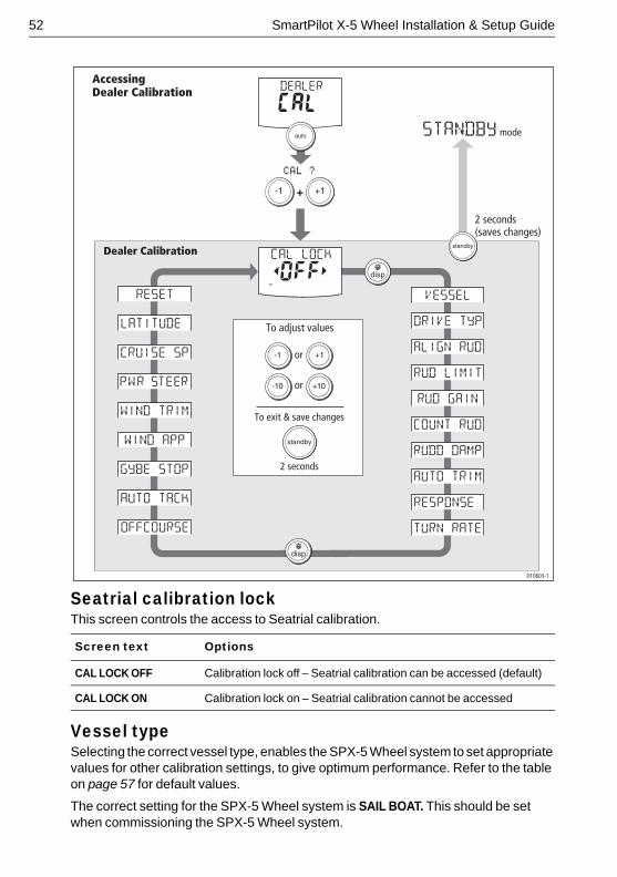
52 SmartPilot X-5 Wheel Installation & Setup Guide
Seatrial calibration lock This screen controls the access to Seatrial calibration.
Vessel type Selecting the correct vessel type, enables the SPX-5 Wheel system to set appropriate values for other calibration settings, to give optimum performance. Refer to the table on page 57 for default values.
The correct setting for the SPX-5 Wheel system is SAIL BOAT. This should be set when commissioning the SPX-5 Wheel system.
Screen text Options
CAL LOCK OFF Calibration lock off – Seatrial calibration can be accessed (default)
CAL LOCK ON Calibration lock on – Seatrial calibration cannot be accessed
AccessingDealer Calibration
Dealer Calibration
D10603-1
To exit & save changes
2 seconds
2 seconds(saves changes)
+
or
or
To adjust values
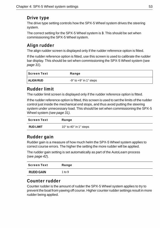
Chapter 4: SPX-5 Wheel system settings 53
Drive type The drive type setting controls how the SPX-5 Wheel system drives the steering system.
The correct setting for the SPX-5 Wheel system is 3. This should be set when commissioning the SPX-5 Wheel system.
Align rudderThe align rudder screen is displayed only if the rudder reference option is fitted.
If the rudder reference option is fitted, use this screen is used to calibrate the rudder bar display. This should be set when commissioning the SPX-5 Wheel system (see page 31).
Rudder limit The rudder limit screen is displayed only if the rudder reference option is fitted.
If the rudder reference option is fitted, this screen is used to set the limits of the rudder control just inside the mechanical end stops, and thus avoid putting the steering system under unnecessary load. This should be set when commissioning the SPX-5 Wheel system (see page 31).
Rudder gain Rudder gain is a measure of how much helm the SPX-5 Wheel system applies to correct course errors. The higher the setting the more rudder will be applied.
The rudder gain setting is set automatically as part of the AutoLearn process (see page 42). .
Counter rudderCounter rudder is the amount of rudder the SPX-5 Wheel system applies to try to prevent the boat from yawing off course. Higher counter rudder settings result in more rudder being applied.
Screen Text Range
ALIGN RUD -9° to +9° in 1° steps
Screen Text Range
RUD LIMIT 10° to 40° in 1° steps
Screen Text Range
RUDD GAIN 1 to 9
54 SmartPilot X-5 Wheel Installation & Setup Guide
The default counter rudder gain is set as part of the initial seatrial AutoLearn process (see page 43).
Rudder dampingIf the SPX-5 Wheel system ‘hunts’ when trying to position the rudder, adjust the rudder damping value to minimize this. Increasing the rudder damping value reduces hunting. Increase the damping one level at a time until the autopilot stops hunting, and always use the lowest acceptable value.
AutoTrim The AutoTrim setting determines the rate at which the SPX-5 Wheel system applies ‘standing helm’ to correct for trim changes caused by varying wind loads on the sails or superstructure.
The default AutoTrim is set as part of the AutoLearn process (see page 43).
If you need to change the setting, increase the AutoTrim one level at a time and use the lowest acceptable value:• If the SPX-5 Wheel system gives unstable course keeping or excessive drive
activity with a change in the heel angle, decrease the AutoTrim level.• If the SPX-5 Wheel system reacts slowly to a heading change due to a change in
the heel angle, increase the AutoTrim level.• If the AutoTrim level is too high, the boat will be less stable and snake around the
desired course.
Response level This sets the default SPX-5 Wheel system response level setting. The response level controls the relationship between course keeping accuracy and the amount of helm/drive activity. You can make temporary changes to response during normal operation (see your Operating Guide for details).
Screen Text Range
COUNT RUD 1 to 9 (Do NOT set to 0)
Screen Text Range
RUDD DAMP 1 to 9
Setting Effect
AUTO TRIM OFF No trim correction
AUTO TRIM 1 to 4 Auto trim applied:1 = Slowest, 4 = Fastest
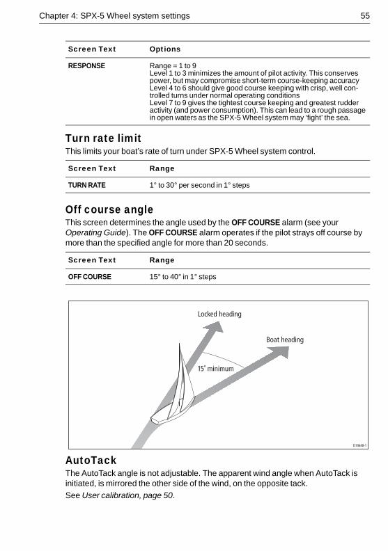
Chapter 4: SPX-5 Wheel system settings 55
Turn rate limitThis limits your boat’s rate of turn under SPX-5 Wheel system control.
Off course angleThis screen determines the angle used by the OFF COURSE alarm (see your Operating Guide). The OFF COURSE alarm operates if the pilot strays off course by more than the specified angle for more than 20 seconds.
AutoTackThe AutoTack angle is not adjustable. The apparent wind angle when AutoTack is initiated, is mirrored the other side of the wind, on the opposite tack.
See User calibration, page 50.
Screen Text Options
RESPONSE Range = 1 to 9 Level 1 to 3 minimizes the amount of pilot activity. This conserves power, but may compromise short-term course-keeping accuracyLevel 4 to 6 should give good course keeping with crisp, well con-trolled turns under normal operating conditionsLevel 7 to 9 gives the tightest course keeping and greatest rudder activity (and power consumption). This can lead to a rough passage in open waters as the SPX-5 Wheel system may ‘fight’ the sea.
Screen Text Range
TURN RATE 1° to 30° per second in 1° steps
Screen Text Range
OFF COURSE 15° to 40° in 1° steps
Locked heading
Boat heading
15˚ minimum
D10648-1
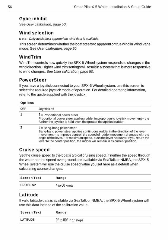
56 SmartPilot X-5 Wheel Installation & Setup Guide
Gybe inhibitSee User calibration, page 50.
Wind selectionNote: Only available if appropriate wind data is available.
This screen determines whether the boat steers to apparent or true wind in Wind Vane mode. See User calibration, page 50.
WindTrimWindTrim controls how quickly the SPX-5 Wheel system responds to changes in the wind direction. Higher wind trim settings will result in a system that is more responsive to wind changes. See User calibration, page 50.
PowerSteerIf you have a joystick connected to your SPX-5 Wheel system, use this screen to select the required joystick mode of operation. For detailed operating information, refer to the guide supplied with the joystick. .
Cruise speedSet the cruise speed to the boat’s typical cruising speed. If neither the speed through the water nor the speed over ground are available via SeaTalk or NMEA, the SPX-5 Wheel system will use the cruise speed value you set here as a default when calculating course changes.
LatitudeIf valid latitude data is available via SeaTalk or NMEA, the SPX-5 Wheel system will use this data instead of the calibration value.
Options
OFF Joystick off
1 1 = Proportional power steerProportional power steer applies rudder in proportion to joystick movement – the further the joystick is held over, the greater the applied rudder.
2 2 = Bang-bang power steerBang-bang power steer applies continuous rudder in the direction of the lever movement – to improve control, the speed of rudder movement changes with the angle of the lever. For maximum speed, push the lever hardover. If you return the lever to the center position, the rudder will remain in its current position.
Screen Text Range
CRUISE SP 4 to 60 knots
Screen Text Range
LATITUDE 0° to 80° in 1° steps
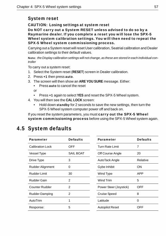
Chapter 4: SPX-5 Wheel system settings 57
System resetCAUTION: Losing settings at system resetDo NOT carry out a System RESET unless advised to do so by a Raymarine dealer. If you complete a reset you will lose the SPX-5 Wheel system calibration settings. You will then need to repeat the SPX-5 Wheel system commissioning process. Carrying out a System reset will reset User calibration, Seatrial calibration and Dealer calibration settings to their default values.
Note: the Display calibration settings will not change, as these are stored in each individual con-troller
To carry out a system reset:1. Select the System reset (RESET) screen in Dealer calibration. 2. Press +1 then press auto.3. The screen will then show an ARE YOU SURE message. Either:
• Press auto to cancel the resetor• Press +1 again to select YES and reset the SPX-5 Wheel system.
4. You will then see the CAL LOCK screen:• Hold down standby for 2 seconds to save the new settings, then turn the
SPX-5 Wheel system computer power off and back on.
If you reset the system parameters, you must carry out the SPX-5 Wheel system commissioning process before using the SPX-5 Wheel system again.
4.5 System defaults
Parameter Defaults Parameter Defaults
Calibration Lock OFF Turn Rate Limit 7
Vessel Type SAIL BOAT Off Course Angle 20
Drive Type 3 AutoTack Angle Relative
Rudder Alignment 0 Gybe Inhibit ON
Rudder Limit 30 Wind Type APP
Rudder Gain 2 Wind Trim 5
Counter Rudder 2 Power Steer (Joystick) OFF
Rudder Damping 2 Cruise Speed 8
AutoTrim 1 Latitude 0
Response: 5 Autopilot Reset OFF

58 SmartPilot X-5 Wheel Installation & Setup Guide
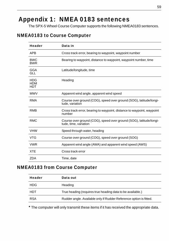
59
Appendix 1: NMEA 0183 sentencesThe SPX-5 Wheel Course Computer supports the following NMEA0183 sentences.
NMEA0183 to Course Computer
NMEA0183 from Course Computer
* The computer will only transmit these items if it has received the appropriate data.
Header Data in
APB Cross track error, bearing to waypoint, waypoint number
BWCBWR
Bearing to waypoint, distance to waypoint, waypoint number, time
GGAGLL
Latitude/longitude, time
HDGHDMHDT
Heading
MWV Apparent wind angle, apparent wind speed
RMA Course over ground (COG), speed over ground (SOG), latitude/longi-tude, variation
RMB Cross track error, bearing to waypoint, distance to waypoint, waypoint number
RMC Course over ground (COG), speed over ground (SOG), latitude/longi-tude, time, variation
VHW Speed through water, heading
VTG Course over ground (COG), speed over ground (SOG)
VWR Apparent wind angle (AWA) and apparent wind speed (AWS)
XTE Cross track error
ZDA Time, date
Header Data out
HDG Heading
HDT True heading (requires true heading data to be available.)
RSA Rudder angle. Available only if Rudder Reference option is fitted.

60 SmartPilot X-5 Wheel Installation & Setup Guide
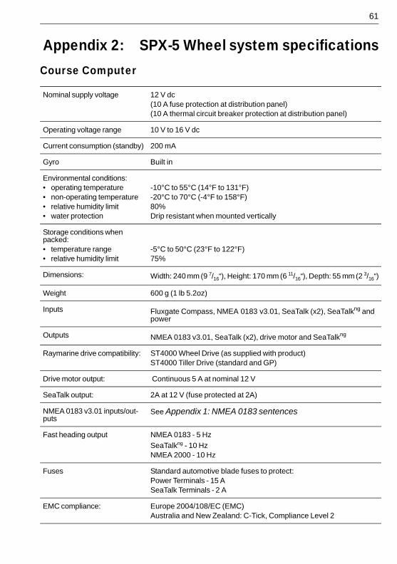
61
Appendix 2: SPX-5 Wheel system specificationsCourse Computer
Nominal supply voltage 12 V dc(10 A fuse protection at distribution panel)(10 A thermal circuit breaker protection at distribution panel)
Operating voltage range 10 V to 16 V dc
Current consumption (standby) 200 mA
Gyro Built in
Environmental conditions:• operating temperature• non-operating temperature• relative humidity limit• water protection
-10°C to 55°C (14°F to 131°F)-20°C to 70°C (-4°F to 158°F)80%Drip resistant when mounted vertically
Storage conditions when packed:• temperature range• relative humidity limit
-5°C to 50°C (23°F to 122°F)75%
Dimensions: Width: 240 mm (9 7/16“), Height: 170 mm (6 11/16“), Depth: 55 mm (2 3/16“)
Weight 600 g (1 lb 5.2oz)
Inputs Fluxgate Compass, NMEA 0183 v3.01, SeaTalk (x2), SeaTalkng and power
Outputs NMEA 0183 v3.01, SeaTalk (x2), drive motor and SeaTalkng
Raymarine drive compatibility: ST4000 Wheel Drive (as supplied with product)ST4000 Tiller Drive (standard and GP)
Drive motor output: Continuous 5 A at nominal 12 V
SeaTalk output: 2A at 12 V (fuse protected at 2A)
NMEA 0183 v3.01 inputs/out-puts
See Appendix 1: NMEA 0183 sentences
Fast heading output NMEA 0183 - 5 Hz
SeaTalkng - 10 HzNMEA 2000 - 10 Hz
Fuses Standard automotive blade fuses to protect:Power Terminals - 15 ASeaTalk Terminals - 2 A
EMC compliance: Europe 2004/108/EC (EMC)Australia and New Zealand: C-Tick, Compliance Level 2
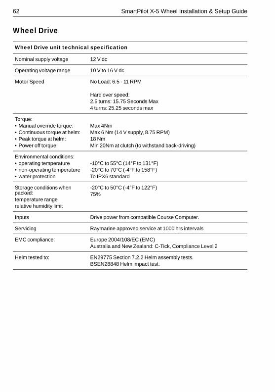
62 SmartPilot X-5 Wheel Installation & Setup Guide
Wheel Drive
Wheel Drive unit technical specification
Nominal supply voltage 12 V dc
Operating voltage range 10 V to 16 V dc
Motor Speed No Load: 6.5 - 11 RPM
Hard over speed:2.5 turns: 15.75 Seconds Max4 turns: 25.25 seconds max
Torque:• Manual override torque:• Continuous torque at helm:• Peak torque at helm: • Power off torque:
Max 4Nm Max 6 Nm (14 V supply, 8.75 RPM)18 NmMin 20Nm at clutch (to withstand back-driving)
Environmental conditions:• operating temperature• non-operating temperature• water protection
-10°C to 55°C (14°F to 131°F)-20°C to 70°C (-4°F to 158°F)To IPX6 standard
Storage conditions when packed:temperature rangerelative humidity limit
-20°C to 50°C (-4°F to 122°F)75%
Inputs Drive power from compatible Course Computer.
Servicing Raymarine approved service at 1000 hrs intervals
EMC compliance: Europe 2004/108/EC (EMC)Australia and New Zealand: C-Tick, Compliance Level 2
Helm tested to: EN29775 Section 7.2.2 Helm assembly tests.BSEN28848 Helm impact test.
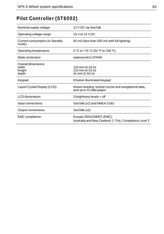
SPX-5 Wheel system specifications 63
Pilot Controller (ST6002)Nominal supply voltage: 12 V DC via SeaTalk
Operating voltage range: 10 V to 15 V DC
Current consumption (in Standby mode)
60 mA (less than 200 mA with full lighting)
Operating temperature: 0 °C to +70 °C (32 °F to 158 °F)
Water protection: waterproof to CFR46
Overall dimensions:widthheightdepth
110 mm (4.33 in)115 mm (4.53 in)41 mm (1.62 in)
Keypad: 8 button illuminated keypad
Liquid Crystal Display (LCD): shows heading, locked course and navigational data, and up to 15 data pages
LCD illumination: 3 brightness levels + off
Input connections: SeaTalk (x2) and NMEA 0183
Output connections: SeaTalk (x2)
EMC compliance: Europe 2004/108/EC (EMC)Australia and New Zealand: C-Tick, Compliance Level 2

64 SmartPilot X-5 Wheel Installation & Setup Guide
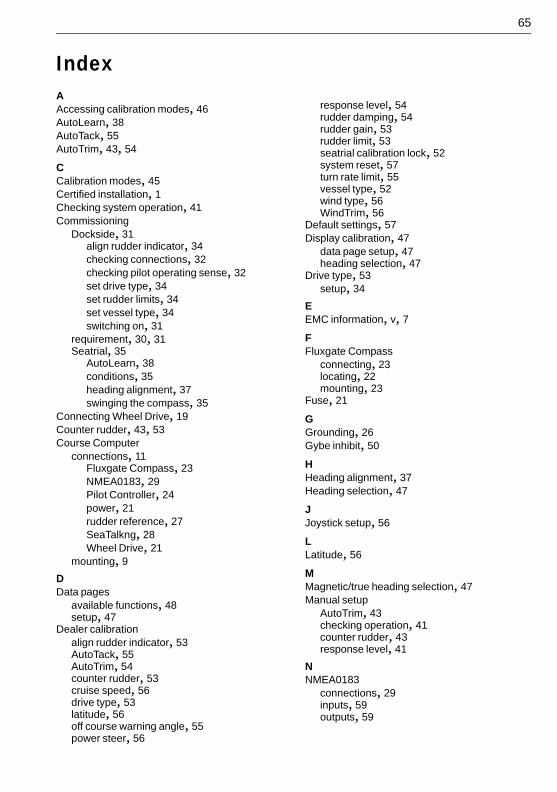
65
IndexAAccessing calibration modes, 46AutoLearn, 38AutoTack, 55AutoTrim, 43, 54
CCalibration modes, 45Certified installation, 1Checking system operation, 41Commissioning
Dockside, 31align rudder indicator, 34checking connections, 32checking pilot operating sense, 32set drive type, 34set rudder limits, 34set vessel type, 34switching on, 31
requirement, 30, 31Seatrial, 35
AutoLearn, 38conditions, 35heading alignment, 37swinging the compass, 35
Connecting Wheel Drive, 19Counter rudder, 43, 53Course Computer
connections, 11Fluxgate Compass, 23NMEA0183, 29Pilot Controller, 24power, 21rudder reference, 27SeaTalkng, 28Wheel Drive, 21
mounting, 9DData pages
available functions, 48setup, 47
Dealer calibrationalign rudder indicator, 53AutoTack, 55AutoTrim, 54counter rudder, 53cruise speed, 56drive type, 53latitude, 56off course warning angle, 55power steer, 56
response level, 54rudder damping, 54rudder gain, 53rudder limit, 53seatrial calibration lock, 52system reset, 57turn rate limit, 55vessel type, 52wind type, 56WindTrim, 56
Default settings, 57Display calibration, 47
data page setup, 47heading selection, 47
Drive type, 53setup, 34
EEMC information, v, 7FFluxgate Compass
connecting, 23locating, 22mounting, 23
Fuse, 21
GGrounding, 26Gybe inhibit, 50
HHeading alignment, 37Heading selection, 47
JJoystick setup, 56
LLatitude, 56
MMagnetic/true heading selection, 47Manual setup
AutoTrim, 43checking operation, 41counter rudder, 43response level, 41
NNMEA0183
connections, 29inputs, 59outputs, 59
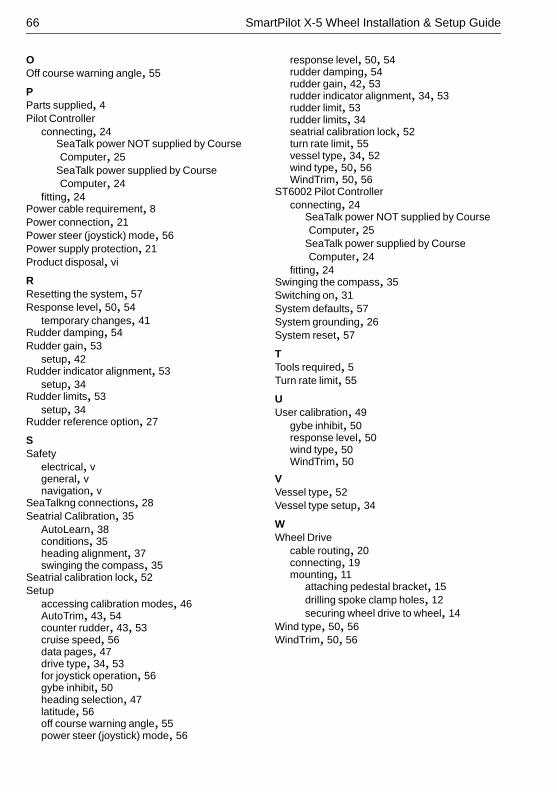
66 SmartPilot X-5 Wheel Installation & Setup Guide
OOff course warning angle, 55
PParts supplied, 4Pilot Controller
connecting, 24SeaTalk power NOT supplied by Course Computer, 25
SeaTalk power supplied by Course Computer, 24
fitting, 24Power cable requirement, 8Power connection, 21Power steer (joystick) mode, 56Power supply protection, 21Product disposal, vi
RResetting the system, 57Response level, 50, 54
temporary changes, 41Rudder damping, 54Rudder gain, 53
setup, 42Rudder indicator alignment, 53
setup, 34Rudder limits, 53
setup, 34Rudder reference option, 27
SSafety
electrical, vgeneral, vnavigation, v
SeaTalkng connections, 28Seatrial Calibration, 35
AutoLearn, 38conditions, 35heading alignment, 37swinging the compass, 35
Seatrial calibration lock, 52Setup
accessing calibration modes, 46AutoTrim, 43, 54counter rudder, 43, 53cruise speed, 56data pages, 47drive type, 34, 53for joystick operation, 56gybe inhibit, 50heading selection, 47latitude, 56off course warning angle, 55power steer (joystick) mode, 56
response level, 50, 54rudder damping, 54rudder gain, 42, 53rudder indicator alignment, 34, 53rudder limit, 53rudder limits, 34seatrial calibration lock, 52turn rate limit, 55vessel type, 34, 52wind type, 50, 56WindTrim, 50, 56
ST6002 Pilot Controllerconnecting, 24
SeaTalk power NOT supplied by Course Computer, 25
SeaTalk power supplied by Course Computer, 24
fitting, 24Swinging the compass, 35Switching on, 31System defaults, 57System grounding, 26System reset, 57
TTools required, 5Turn rate limit, 55
UUser calibration, 49
gybe inhibit, 50response level, 50wind type, 50WindTrim, 50
VVessel type, 52Vessel type setup, 34
WWheel Drive
cable routing, 20connecting, 19mounting, 11
attaching pedestal bracket, 15drilling spoke clamp holes, 12securing wheel drive to wheel, 14
Wind type, 50, 56WindTrim, 50, 56
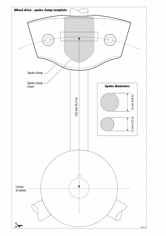
Spoke clamp
Spoke diameters
Wheel drive - spoke clamp template
Center of wheel
Spoke clampinsert
D5410-1
135
mm
(5.3
in)
16 m
m (5
/8 in
)12
mm
(1/2
in)


