124
IG 0100 BEN_I (1010) translation of the original instructions EN Operating Instructions SmartTest HLT 550 HLT 560 HLT 570 EN (505)872-0037 www.idealvac.com
IG 0
100
BE
N_I
(10
10)
tran
slat
ion
of
the
ori
gin
al in
stru
ctio
ns
EN
Operating Instructions
SmartTestHLT 550HLT 560HLT 570
EN
(505)872-0037
www.idealvac.com
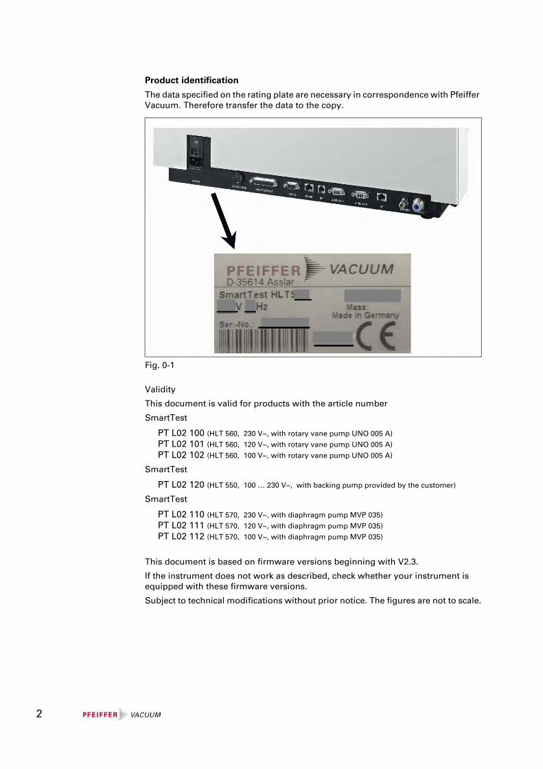
Product identification
The data specified on the rating plate are necessary in correspondence with Pfeiffer Vacuum. Therefore transfer the data to the copy.
Validity
This document is valid for products with the article number
SmartTest
PT L02 100 (HLT 560, 230 V~, with rotary vane pump UNO 005 A)
PT L02 101 (HLT 560, 120 V~, with rotary vane pump UNO 005 A)
PT L02 102 (HLT 560, 100 V~, with rotary vane pump UNO 005 A)
SmartTest
PT L02 120 (HLT 550, 100 … 230 V~, with backing pump provided by the customer)
SmartTest
PT L02 110 (HLT 570, 230 V~, with diaphragm pump MVP 035)
PT L02 111 (HLT 570, 120 V~, with diaphragm pump MVP 035)
PT L02 112 (HLT 570, 100 V~, with diaphragm pump MVP 035)
This document is based on firmware versions beginning with V2.3.
If the instrument does not work as described, check whether your instrument is equipped with these firmware versions.
Subject to technical modifications without prior notice. The figures are not to scale.
Fig. 0-1
2
Content
1 Safety 71.1 Directions for Use 71.1.1 Use of this Manual 71.1.2 Symbols Used 71.2 General Safety Precautions 81.2.1 Use for the Intended Purpose 81.2.2 Responsibility and Guarantee 101.2.3 Personnel 101.2.4 General Safety Rules 111.3 Scope of Delivery 14
2 Technical Data 152.1 General 152.2 Mains Connection 152.3 Environmental Data 152.4 Measure 162.5 Interfaces 172.6 Backing Pumps 172.7 Turbo Pump 18
3 Description 193.1 Measuring System 203.2 Detection Principles 213.3 Leak Detection Methods 223.4 Test Gases 243.5 Background Suppression 25
4 Manual Control Elements 294.1 Instrument Operation 29
5 Commissioning 305.1 Installation, Assembly 305.1.1 Unpacking 305.1.2 Carrying / Transport 305.1.3 Transport Lock 315.2 Mount the External Backing Pump 315.3 Mounting Accessories 325.3.1 Sniffing Probe 325.3.2 Remote Control 325.3.3 Bypass Option 335.3.4 Signal tower 335.3.5 Exhaust pipe 335.3.6 Venting Line 335.4 Mains Connection 33
6 Operation 356.1 Switching On and Off 356.2 Ready to start 396.2.1 Regeneration 406.2.2 Check internal test leak 406.2.3 Setup 40
3
6.2.4 Calibration 416.2.5 Measuring mode Vacuum / Sniffing 416.3 Measure 436.3.1 Measure with a test item 436.3.1.1 Vacuum mode 436.3.1.2 Sniffing mode 436.3.2 Measured Value Display 446.3.3 Display Range Settings 456.3.4 Volume 456.4 Setup 466.4.1 View 466.4.1.1 Contrast 476.4.1.2 Units 486.4.1.3 Time & Date 496.4.1.4 Display Range 496.4.1.5 Lower Display Limit 506.4.1.6 Background at “Ready to Start” 516.4.2 Access Control 516.4.2.1 Change Menu-PIN 526.4.2.2 Change Device PIN 536.4.2.3 Calibration Enabled 546.4.2.4 Maintenance enabled 556.4.3 Language 566.4.4 User Settings 566.4.4.1 Mode & Mass 576.4.4.2 Filter & Zero 596.4.4.3 Alarm 616.4.4.4 Interfaces 626.4.4.4.1 Analog Output 636.4.4.4.2 Compact Gauge 656.4.4.4.3 Control Location 666.4.4.4.4 Relay 676.4.4.4.5 Serial Port 686.4.4.4.6 Bypass Option 696.4.4.5 Parameter save / load 706.4.4.5.1 Load PARA Set 1 / 2 706.4.4.5.2 Load Factory Settings 716.4.4.5.3 Save PARA Set 1 / 2 716.4.4.6 Monitoring functions 726.4.4.6.1 Flow 726.4.4.6.2 Contamination Protection 736.4.4.6.3 Volume & Beep 746.4.4.6.4 Valves 756.4.4.6.5 Evacuation Time & Vent 766.4.4.6.6 Calibration Request 786.4.5 Calibration Settings 796.4.6 Information 806.4.6.1 Settings 806.4.6.2 System Data 816.4.6.3 Vacuum System 816.4.6.4 Error List 826.4.6.5 Calibration History 826.4.6.6 Paging function remote control RC 500 WL 836.4.7 Maintenance and Service 846.4.7.1 Maintenance device 846.4.7.2 Burn In 856.4.7.3 Maintenance Interval Components 86
4
6.4.7.4 Maintenance List 866.4.7.5 Service 876.5 Calibration Vacuum Method 886.6 Calibration Sniffing Method 926.7 Measuring the Internal Test Leak 95
7 Errors 977.1 Malfunction Messages 977.2 Warnings 1017.3 Changing Mains Fuses 105
8 Disposal 107
9 Accessories and Consumer Materials 108
Appendix 110A Remote Control RC 500 WL 110B Interfaces 111C List of Default Values 117D Pirani-Characteristic 119E List of literature 120F Declaration of Contamination 120G Declaration of Conformity 121
5

6
1 Safety
1.1 Directions for Use
1.1.1 Use of this Manual
This chapter describes the safety requirements which must be observed on all accounts when using the SmartTest Helium Leak Detector.
All persons working on and with the leak detector must have read and understood the chapters relevant to their activities. This chapter is binding for all persons and all activities.
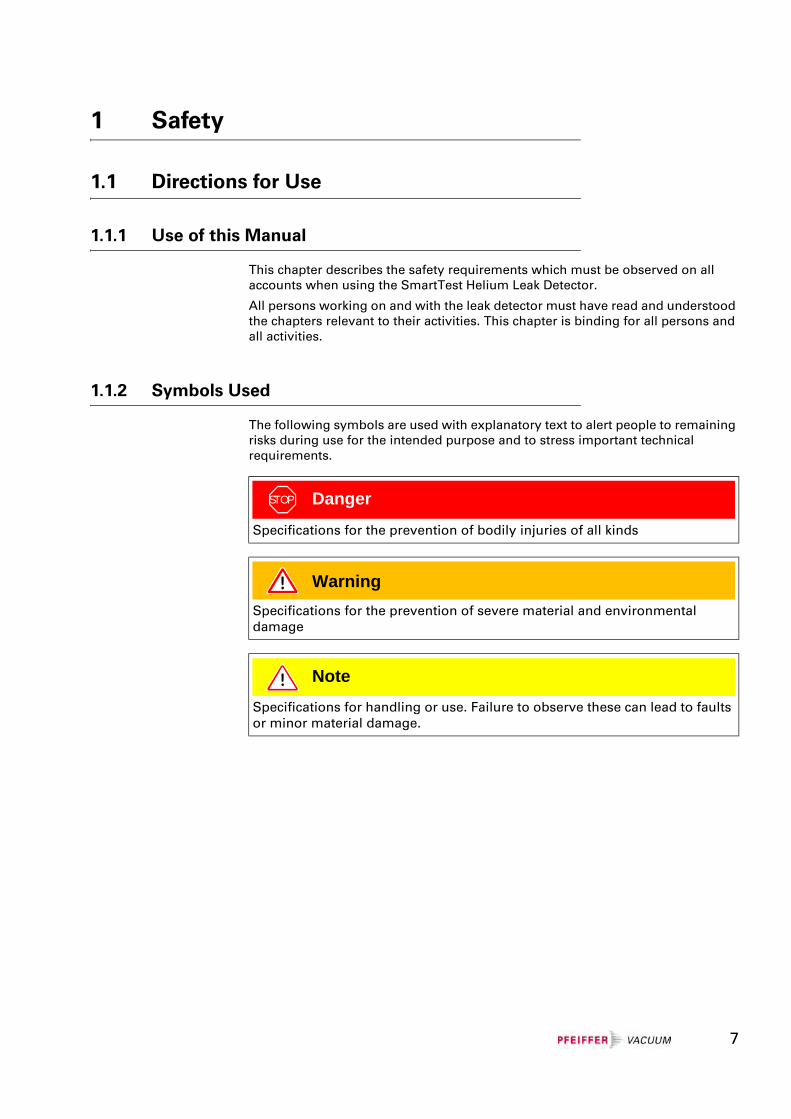
1.1.2 Symbols Used
The following symbols are used with explanatory text to alert people to remaining risks during use for the intended purpose and to stress important technical requirements.
STOP Danger
Specifications for the prevention of bodily injuries of all kinds
WarningSpecifications for the prevention of severe material and environmental damage
NoteSpecifications for handling or use. Failure to observe these can lead to faults or minor material damage.
7
1.2 General Safety Precautions
1.2.1 Use for the Intended Purpose
The SmartTest Helium Leak Detectors serve for measurement and localization of small and very small leaks both on components and modules and on fittings and systems. They are suitable both for underpressure leak testing (vacuum method with or without partial current operation) and for overpressure leak testing (sniffing method).
The SmartTest Helium Leak Detectors may only be used for leak testing for the gases specified in the ”Technical Data”.
The SmartTest Helium Leak Detectors are designed specially for industrial applications and are used:
• For quality control in manufacturing processes,
• for quality control of production plants,
• as a service unit.
Use for the intended purpose also includes:
• Use of standard and original accessories,
• observance of this document and compliance with the instructions and regulations therein.
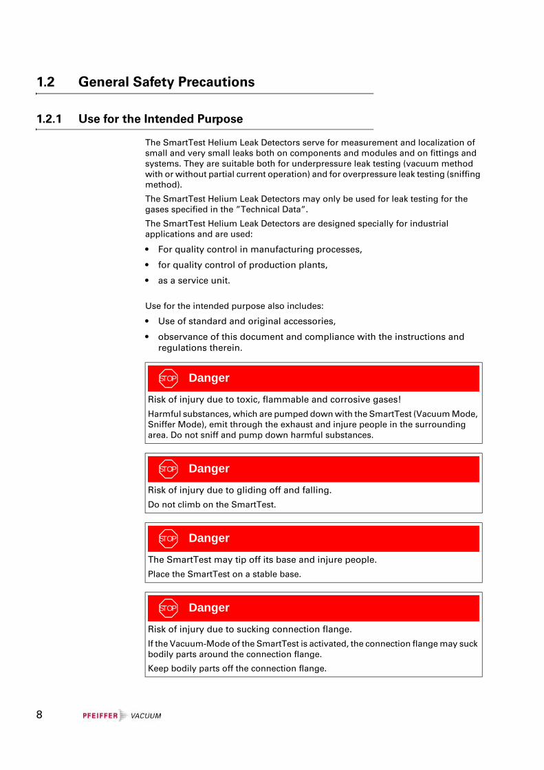
STOP Danger
Risk of injury due to toxic, flammable and corrosive gases!
Harmful substances, which are pumped down with the SmartTest (Vacuum Mode, Sniffer Mode), emit through the exhaust and injure people in the surrounding area. Do not sniff and pump down harmful substances.
STOP Danger
Risk of injury due to gliding off and falling.
Do not climb on the SmartTest.
STOP Danger
The SmartTest may tip off its base and injure people.
Place the SmartTest on a stable base.
STOP Danger
Risk of injury due to sucking connection flange.
If the Vacuum-Mode of the SmartTest is activated, the connection flange may suck bodily parts around the connection flange.
Keep bodily parts off the connection flange.
8
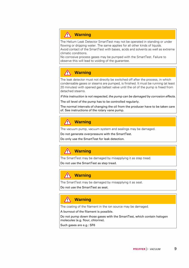
WarningThe Helium Leak Detector SmartTest may not be operated in standing or under flowing or dripping water. The same applies for all other kinds of liquids.Avoid contact of the SmartTest with bases, acids and solvents as well as extreme climatic conditions.No corrosive process gases may be pumped with the SmartTest. Failure to observe this will lead to voiding of the guarantee.
WarningThe leak detector must not directly be switched off after the process, in which condensable gases or steams are pumped, is finished. It must be running (at least 20 minutes) with opened gas ballast valve until the oil of the pump is freed from detached steams.
If this instruction is not respected, the pump can be damaged by corrosion effects.
The oil level of the pump has to be controlled regularly.
The normal intervals of changing the oil from the producer have to be taken care of. See instructions of the rotary vane pump.
WarningThe vacuum pump, vacuum system and sealings may be damaged.
Do not generate overpressure with the SmartTest.
Do only use the SmartTest for leak detection.
WarningThe SmartTest may be damaged by misapplying it as step tread.
Do not use the SmartTest as step tread.
WarningThe SmartTest may be damaged by misapplying it as seat.
Do not use the SmartTest as seat.
WarningThe coating of the filament in the ion source may be damaged.
A burnout of the filament is possible.
Do not pump down those gases with the SmartTest, which contain halogen molecules (e.g. flour, chlorine).
Such gases are e.g.: SF6
9
1.2.2 Responsibility and Guarantee
Pfeiffer Vacuum will accept no responsibility and provide no guarantee and exclude itself from all liability in the event that the user or third parties
• use the product for a purpose for which it was not intended,
• fail to observe the ”Technical Data”,
• manipulate the product in any way (conversions, modifications, etc.),
• operate the product with accessories which are not listed in the appropriate product documentation.
1.2.3 Personnel
Operating personnel
The operating personnel may operate the SmartTest leak detector in normal operation. The normal operation includes only the following activities:
• Operation,
• the care and maintenance work described in this document.
NoteCaution: Danger of injury
Although this instrument is distinguished by high standards of quality and safety and has been built and tested according to the latest state of the art, injury or material damages cannot be totally ruled out in the event of misuse or use for a purpose which was not intended.
Therefore read this document carefully and especially observe the ”Safety” chapter. Keep this document close to the instrument at all times.
NoteThe SmartTest may be damaged by wrong handling.
Do only run the SmartTest under the allowed conditions of temperature (+10° C to +35° C) and relative humidity (max. 80% up to +31° C, decreasing to 50% at +35° C). (See also chapter 2.3)
NoteThe SmartTest may be damaged due to lack of inspections.
In order to prevent subsequent damages, check the exterior of the SmartTest frequently relating to optical damages, and follow the Maintenance Instructions frequently.
10
Maintenance personnel
The maintenance personnel may operate the SmartTest leak detector in normal operation and perform maintenance work necessary for trouble-free operation of the instrument.
In order to be authorised to maintain the SmartTest leak detector, the person concerned must have taken part in an initial training conducted by a Pfeiffer Vacuum employee or an experienced member of staff of the system user. (See Maintenance Instructions IG 0108 BEN for further information.)
Service personnel
The service personnel may operate the SmartTest leak detector in normal operation and perform maintenance and service work.
The SmartTest leak detector may be serviced only by trained Pfeiffer Vacuum staff or trained employees of the system user with a similar qualification.
Training as a master electrician or a similar professional training is necessary in order to work on the electrical components.
See Maintenance Instructions IG 0108 BEN for further information.
1.2.4 General Safety Rules
Legal regulations
The generally applicable legal and otherwise binding regulations for the prevention of accidents and protection of the environment must be observed in addition to this document.
Such regulations may also extend to the handling of hazardous substances or provision/wearing of personal safety equipment etc. for example.
Probable risk
On suspicion that safe operation is no longer possible, the instrument must be taken out of operation and secured against accidental starting.
This may be the case:
• when the device shows visible signs of damage
• when liquid has penetrated the instrument
• when the instrument is no longer working
• after long periods of storage under adverse conditions
• after great transport stress
Energy connections, protective earthing
Make sure the instrument is suitable for operating on the local power supply before connecting it.
The mains plug may only be plugged into a shockproof socket
11
Installation of protective devices
An exhaust pipe must be installed under certain circumstances.
See Chapter 5.1.2.
Misuse of protective devices
Only fuses of the specified type with the specified current rating may be used as replacements.
Opening the instrument
Sending in for repairs
STOP Danger
Caution: Mains voltage
Improperly earthed products may be dangerous to life in the event of a malfunction.
Connect the product in accordance with local regulations and earth correctly. Interruption of the earthed conductor inside or outside the instrument is not permissible.
STOP Danger
Caution: Mains voltage, hot parts and rotating components
Removal of the housing shells is dangerous to life and limb.
The housing shells may never be removed in the course of the work described in this document.
WarningProducts returned to Pfeiffer Vacuum for service or repair must be free of harmful substances (e.g. radioactive, toxic, caustic or microbiological).
Forwarding contaminated products:
- Adhere to the forwarding regulations of all involved countries and forwarder companies.
- Enclose a completed Declaration of Contamination.
- Declare all dangers on the package.
Products which are not clearly declared as “free from potentially harmful substances” will be decontaminated at the expense of the customer.
12

A completed and signed "Contamination Declaration" (see: www.pfeiffer-vacuum.net and appendix Declaration of Contamination) must be enclosed with every product sent in for repair.
Spare parts
Only original spare parts may be used for repairs. See maintenance Instructions IG 0108 BEN.
13
1.3 Scope of Delivery
The scope of delivery includes the following parts:
• Basic device HLT 5xx
• Power-Subcon; relay plug
• Cap for Power-Subcon; relay plug
• Connecting plug: Ventilation sniffer connection
• Filter mat fan 500 μm
• Power cable
• Set of hexagonal wrenches
• Set of fuses
• Documentation
14
2 Technical Data
2.1 General
2.2 Mains Connection
2.3 Environmental Data
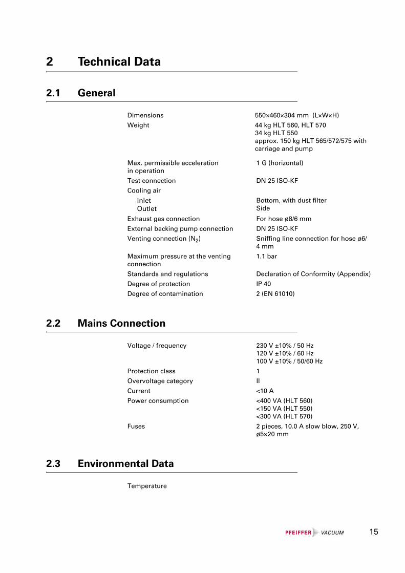
Dimensions 550×460×304 mm (L×W×H)
Weight 44 kg HLT 560, HLT 57034 kg HLT 550approx. 150 kg HLT 565/572/575 with carriage and pump
Max. permissible accelerationin operation
1 G (horizontal)
Test connection DN 25 ISO-KF
Cooling air
InletOutlet
Bottom, with dust filterSide
Exhaust gas connection For hose ø8/6 mm
External backing pump connection DN 25 ISO-KF
Venting connection (N2) Sniffing line connection for hose ø6/4 mm
Maximum pressure at the venting connection
1.1 bar
Standards and regulations Declaration of Conformity (Appendix)
Degree of protection IP 40
Degree of contamination 2 (EN 61010)
Voltage / frequency 230 V ±10% / 50 Hz120 V ±10% / 60 Hz100 V ±10% / 50/60 Hz
Protection class 1
Overvoltage category II
Current <10 A
Power consumption <400 VA (HLT 560) <150 VA (HLT 550) <300 VA (HLT 570)
Fuses 2 pieces, 10.0 A slow blow, 250 V, ø5×20 mm
Temperature
15
2.4 Measure
Vacuum mode
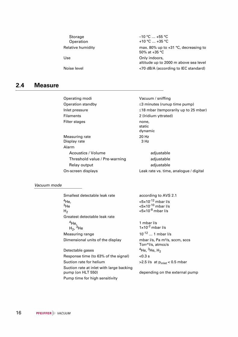
StorageOperation
–10 °C … +55 °C+10 °C … +35 °C
Relative humidity max. 80% up to +31 °C, decreasing to 50% at +35 °C
Use Only indoors,altitude up to 2000 m above sea level
Noise level <70 dB/A (according to IEC standard)
Operating modi Vacuum / sniffing
Operation standby ≤3 minutes (runup time pump)
Inlet pressure ≤18 mbar (temporarily up to 25 mbar)
Filaments 2 (Iridium yttrated)
Filter stages none,staticdynamic
Measuring rateDisplay rate
20 Hz 3 Hz
Alarm
Acoustics / Volume adjustable
Threshold value / Pre-warning adjustable
Relay output adjustableOn-screen displays Leak rate vs. time, analogue / digital
Smallest detectable leak rate4He,3HeH2
according to AVS 2.1
<5×10-12 mbar l/s <5×10⁻¹⁰ mbar l/s<5×10-8 mbar l/s
Greatest detectable leak rate4He,H2, 3He
1 mbar l/s1×10-2 mbar l/s
Measuring range 10-12 … 1 mbar l/s
Dimensional units of the display mbar l/s, Pa m³/s, sccm, sccsTorr*l/s, atmcc/s
Detectable gases 4He, 3He, H2
Response time (to 63% of the signal) <0.3 s
Suction rate for helium >2.5 l/s at pinlet < 0.5 mbar
Suction rate at inlet with large backing pump (on HLT 550) depending on the external pump
Pump time for high sensitivity
16
Sniffing mode
2.5 Interfaces
Connecting plug arrangement and detailed data, see Communication Protocol IG 0105 BEN.
2.6 Backing Pumps
HLT 550
HLT 560
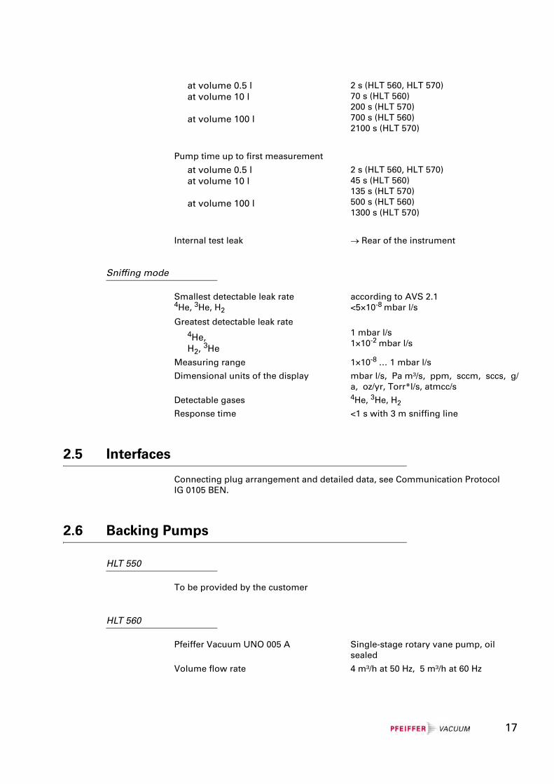
at volume 0.5 lat volume 10 l
at volume 100 l
2 s (HLT 560, HLT 570)70 s (HLT 560)200 s (HLT 570)700 s (HLT 560)2100 s (HLT 570)
Pump time up to first measurement
at volume 0.5 lat volume 10 l
at volume 100 l
2 s (HLT 560, HLT 570)45 s (HLT 560)135 s (HLT 570)500 s (HLT 560)1300 s (HLT 570)
Internal test leak → Rear of the instrument
Smallest detectable leak rate4He, 3He, H2
Greatest detectable leak rate4He, H2, 3He
according to AVS 2.1<5×10⁻⁸ mbar l/s
1 mbar l/s1×10-2 mbar l/s
Measuring range 1×10⁻⁸ … 1 mbar l/s
Dimensional units of the display mbar l/s, Pa m³/s, ppm, sccm, sccs, g/a, oz/yr, Torr*l/s, atmcc/s
Detectable gases 4He, 3He, H2
Response time <1 s with 3 m sniffing line
To be provided by the customer
Pfeiffer Vacuum UNO 005 A Single-stage rotary vane pump, oil sealed
Volume flow rate 4 m³/h at 50 Hz, 5 m³/h at 60 Hz
17
HLT570
2.7 Turbo Pump
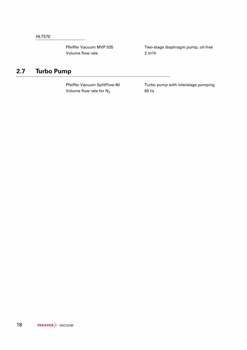
Pfeiffer Vacuum MVP 035 Two-stage diaphragm pump, oil-free
Volume flow rate 2 m³/h
Pfeiffer Vacuum SplitFlow 80 Turbo pump with interstage pumping
Volume flow rate for N2 60 l/s
18
3 Description
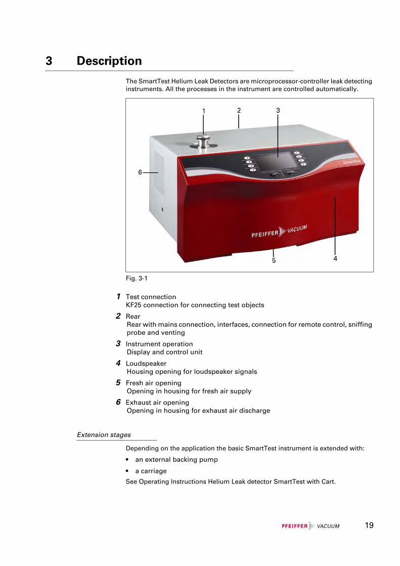
The SmartTest Helium Leak Detectors are microprocessor-controller leak detecting instruments. All the processes in the instrument are controlled automatically.
1 Test connectionKF25 connection for connecting test objects
2 RearRear with mains connection, interfaces, connection for remote control, sniffing probe and venting
3 Instrument operationDisplay and control unit
4 LoudspeakerHousing opening for loudspeaker signals
5 Fresh air openingOpening in housing for fresh air supply
6 Exhaust air openingOpening in housing for exhaust air discharge
Extension stages
Depending on the application the basic SmartTest instrument is extended with:
• an external backing pump
• a carriage
See Operating Instructions Helium Leak detector SmartTest with Cart.
Fig. 3-1
19
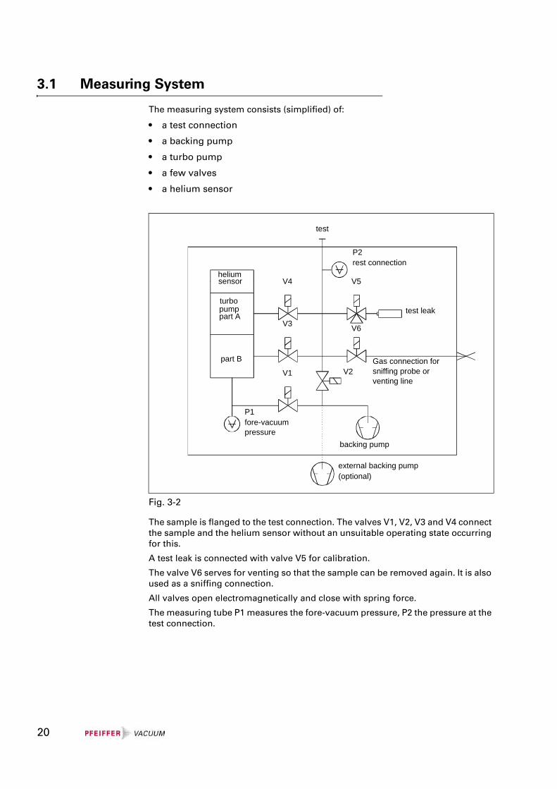
3.1 Measuring System
The measuring system consists (simplified) of:
• a test connection
• a backing pump
• a turbo pump
• a few valves
• a helium sensor
The sample is flanged to the test connection. The valves V1, V2, V3 and V4 connect the sample and the helium sensor without an unsuitable operating state occurring for this.
A test leak is connected with valve V5 for calibration.
The valve V6 serves for venting so that the sample can be removed again. It is also used as a sniffing connection.
All valves open electromagnetically and close with spring force.
The measuring tube P1 measures the fore-vacuum pressure, P2 the pressure at the test connection.
Fig. 3-2
V4
V3
V1
V6
V5
V2
test leakturbopumppart A
heliumsensor
part B
P1fore-vacuumpressure
backing pump
external backing pump(optional)
test
P2rest connection
Gas connection forsniffing probe orventing line
20
3.2 Detection Principles
Counterflow
The sample is connected to the backing pump via valve V2. At a pressure p2 £ 15 mbar *) the valve V1 to the turbo pump is opened. Helium can get to the helium sensor through the two partial pumps A and B against the pumping direction. The mass-dependent compression capacity of the two partial pumps keeps away heavy gases. The proportion of helium which gets through to the helium sensor depends on the suction performance of the backing pump and the compressions of the two partial pumps.
Twin-Flow™
The gas flow from the sample goes through the test connection.
Twin-Flow™ low: At pressure p2 < 5 mbar*) V1 and V3 are open
Twin-Flow™ high: At pressure p2 < 0.5 mbar*) V1 and V4 are open
The gas flow passes through partial pump B to the backing pump and the test connection is pumped up to high vacuum. The suction performance of the partial pump B is approx. 40 l/s. Only the partial pump A acts in counterflow and allows light gasses such as hydrogen and helium to get through to the helium sensor on account of the mass-dependent compression capacity.
21
3.3 Leak Detection Methods
When searching for leaks with the SmartTest the test gas entering or escaping through leaks in the sample is detected.
For gas to flow through a leak a pressure difference between the inside and outside of the sample is necessary. For this either excess pressure or vacuum pressure is generated inside the sample.
Vacuum method
In the vacuum method test gas is blown against the wall of the evacuated sample from the atmosphere side. It enters the sample at leaks and is fed to the leak detector.
The sample must be vacuum pressure-proof.
The sensitivity stages
counterflow ⇒ Twin-Flow™ low ⇒ Twin-Flow™ high
are run through.
The detection limit is lower than in the sniffing method. The helium concentration at the leak must be known in order to quantify the leak. The state of equilibrium must be waited for.
* Factory settings. Other valve settings. See Chapter 6.4.4.6.4.
22
Sniffing method
In the sniffing method the test gas escaping from leaks in the sample into the atmosphere is detected.
The sample must withstand the applied test pressure.
In operation with the sniffing probe a constant gas flow is sucked in from the atmosphere. The helium proportion of the air (5.2 ppm) causes a leak rate display of approx. 1×10⁻⁶ mbar l/s which can be eliminated by the ZERO function.
To detect a leak, the sniffing probe is applied to the points of the sample under helium overpressure which are suspected of leaking. An increased leak rate value indicates an increased concentration of helium and therefore a leak. The higher the pressure and the helium concentration in the sample, the smaller the leaks which can be detected.
The sensitivity stages
counterflow ⇒ Twin-Flow™ low
are run through.
The detection sensitivity and the quantifiability of the leak rate are less favourable than in the vacuum pressure leak detection.
23
3.4 Test Gases
For reasons of economy and detection sensitivity 4He (helium with mass 4) is generally used as a test gas for leak detection. Under certain conditions, e.g. at increased 4He concentration on the sample, it may be useful to change to a different test gas such as 3He (helium with mass 3) or H2 (hydrogen, mass 2). These gases can also be detected with the leak detector.
STOP Danger
Caution: Danger of explosion
Hydrogen forms a highly explosive gas mixture with air.
Great caution is necessary when using hydrogen! No smoking, no naked flames, avoid sparks.
NoteBecause of the high percentage of water in typical residual gases, the leak rate background in the measurement of hydrogen is fairly high (in a range from 10-7 mbar l/s).
For the leak detection the test gas can be diluted with a neutral gas such as nitrogen or argon. This helps to reduce contamination of the atmosphere and an increase in the signal background especially in case of serious leaks. The leak rate signal is then of course reduced according to the test gas concentration.
24
3.5 Background Suppression
The background signal may increase dependent on the measuring conditions (e.g. high percentage of helium in the ambient air).
The background signal can be suppressed to enable easy measurement of small leak rates despite a high background.
The background suppression can be locked or activated automatically with every START. See Chapter 6.4.4.2.
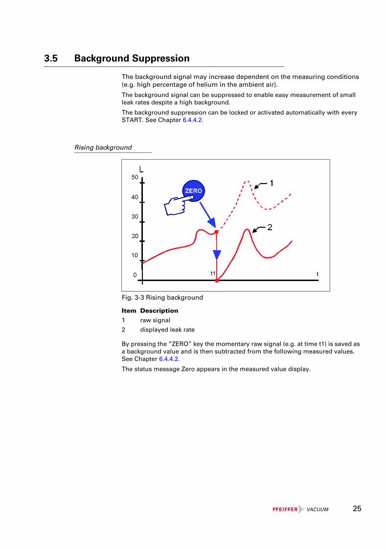
Rising background
By pressing the ”ZERO” key the momentary raw signal (e.g. at time t1) is saved as a background value and is then subtracted from the following measured values. See Chapter 6.4.4.2.
The status message Zero appears in the measured value display.
Fig. 3-3 Rising background
Item Description1 raw signal
2 displayed leak rate
25
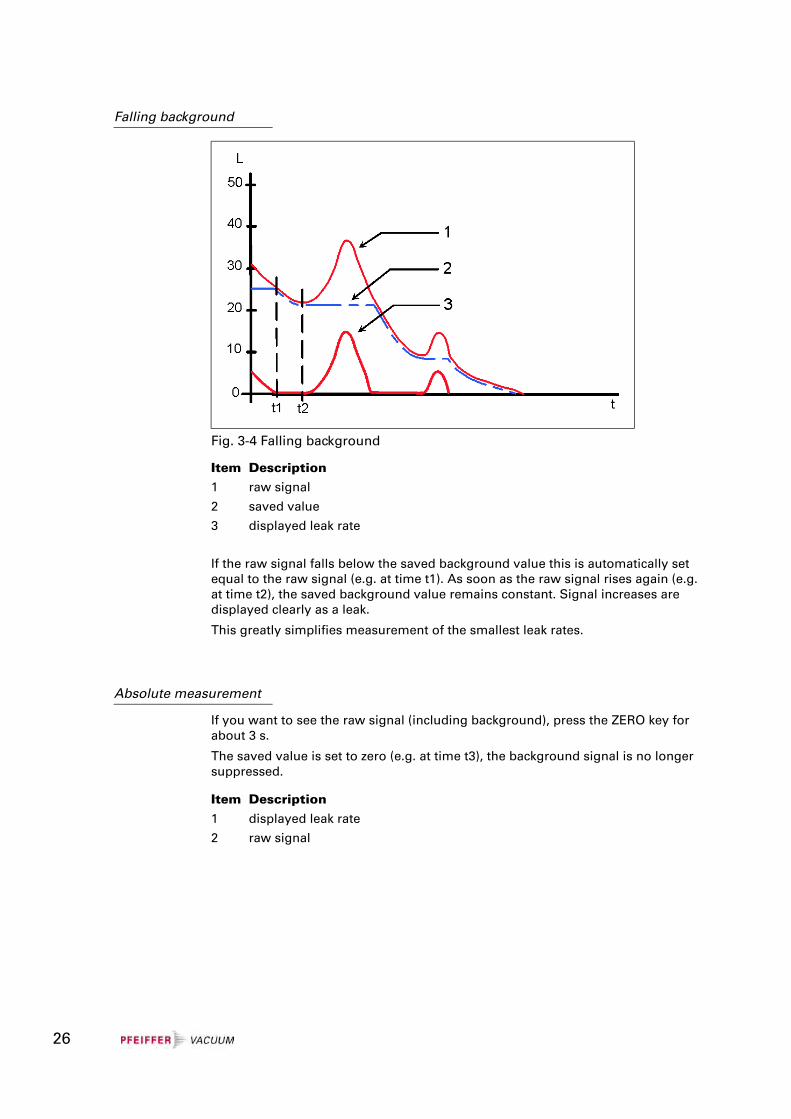
Falling background
If the raw signal falls below the saved background value this is automatically set equal to the raw signal (e.g. at time t1). As soon as the raw signal rises again (e.g. at time t2), the saved background value remains constant. Signal increases are displayed clearly as a leak.
This greatly simplifies measurement of the smallest leak rates.
Absolute measurement
If you want to see the raw signal (including background), press the ZERO key for about 3 s.
The saved value is set to zero (e.g. at time t3), the background signal is no longer suppressed.
Fig. 3-4 Falling background
Item Description1 raw signal
2 saved value
3 displayed leak rate
Item Description1 displayed leak rate
2 raw signal
26
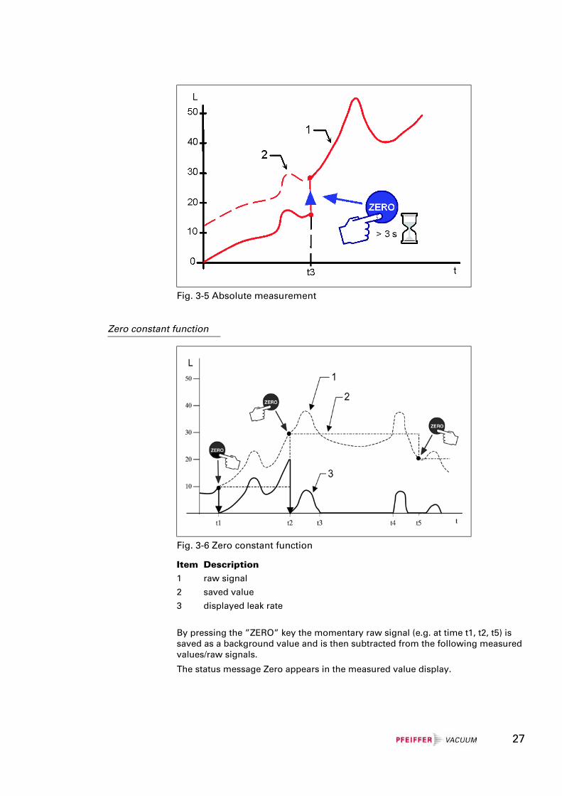
Zero constant function
By pressing the ”ZERO” key the momentary raw signal (e.g. at time t1, t2, t5) is saved as a background value and is then subtracted from the following measured values/raw signals.
The status message Zero appears in the measured value display.
Fig. 3-5 Absolute measurement
Fig. 3-6 Zero constant function
Item Description1 raw signal
2 saved value
3 displayed leak rate
27

The automatic background suppression is locked. The zero value is retained after pressing the Stop key. Pressing the Zero key again overwrites the zero value. The zero value is set to ”0” at Power Off or changing the zero function.
If the raw signal of the leak rate drops below the saved value/background value (see time: t3 to t4), it is not evaluated but the slightest detectable leak rate/detection limit is displayed.
So leaks are not displayed (raw signal) that are smaller than the saved underground value (saved value).
28
29
4 Manual Control Elements
4.1 Instrument Operation
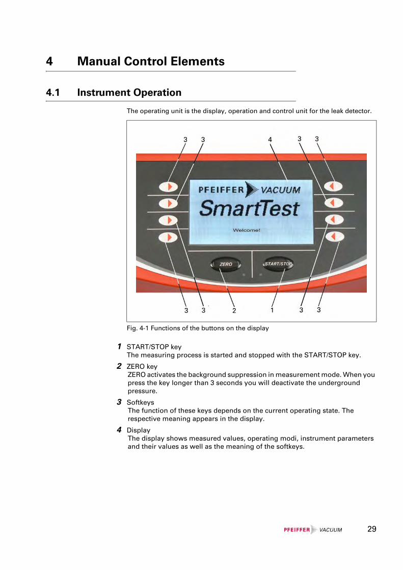
The operating unit is the display, operation and control unit for the leak detector.
1 START/STOP keyThe measuring process is started and stopped with the START/STOP key.
2 ZERO keyZERO activates the background suppression in measurement mode. When you press the key longer than 3 seconds you will deactivate the underground pressure.
3 SoftkeysThe function of these keys depends on the current operating state. The respective meaning appears in the display.
4 DisplayThe display shows measured values, operating modi, instrument parameters and their values as well as the meaning of the softkeys.
Fig. 4-1 Functions of the buttons on the display
5 Commissioning
5.1 Installation, Assembly
Despite good attenuation and vibration decoupling of the mechanical pumps in the SmartTest, vibrations of the instruments can never be ruled out totally.
To avoid humming (vibration of the instrument on a base with a similar resonance frequency) a firm, stable base should be chosen which only exhibits a slight tendency to vibrate.
5.1.1 Unpacking
The leak detector is delivered in a special packing ready for operation.
5.1.2 Carrying / Transport
NoteSee the Chapter ”Technical Data” (Chapter 2) regarding the permissible ambient temperature, degree of protection, voltages, max. acceleration of the instrument in operation etc.
NoteThe packing must be checked for damage before unpacking. If damage to the packing or the instrument itself is visible, please file a damage report with the shipping agent responsible immediately.
We recommend you to keep the special packing. This original packing offers the best protection for transport over a great distance or for returning the leak detector for servicing.
NoteOnly applies for type HLT560.
The pump (with oil filling) may be tilted by a maximum of 90°. In operation by a maximum 10°.
STOP Danger
Caution: Heavy productWhen carrying heavy items your back can be injured or other injuries can occur when the item slips out of your hands.
Two people should carry the product.
30
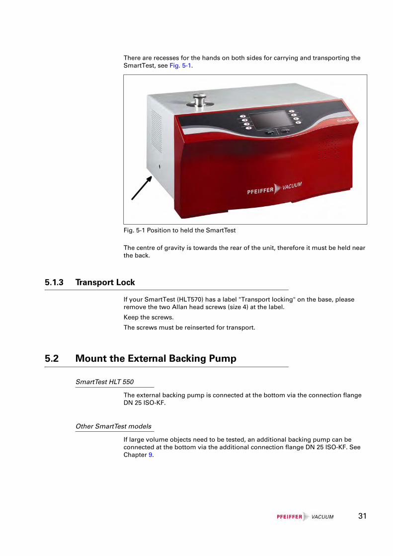
There are recesses for the hands on both sides for carrying and transporting the SmartTest, see Fig. 5-1.
The centre of gravity is towards the rear of the unit, therefore it must be held near the back.
5.1.3 Transport Lock
If your SmartTest (HLT570) has a label "Transport locking" on the base, please remove the two Allan head screws (size 4) at the label.
Keep the screws.
The screws must be reinserted for transport.
5.2 Mount the External Backing Pump
SmartTest HLT 550
The external backing pump is connected at the bottom via the connection flange DN 25 ISO-KF.
Other SmartTest models
If large volume objects need to be tested, an additional backing pump can be connected at the bottom via the additional connection flange DN 25 ISO-KF. See Chapter 9.
Fig. 5-1 Position to held the SmartTest
31
5.3 Mounting Accessories
5.3.1 Sniffing Probe
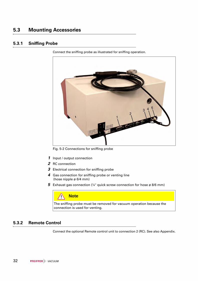
Connect the sniffing probe as illustrated for sniffing operation.
1 Input / output connection
2 RC connection
3 Electrical connection for sniffing probe
4 Gas connection for sniffing probe or venting line(hose nipple ø 6/4 mm)
5 Exhaust gas connection (¼" quick screw connection for hose ø 8/6 mm)
5.3.2 Remote Control
Connect the optional Remote control unit to connection 2 (RC). See also Appendix.
Fig. 5-2 Connections for sniffing probe
NoteThe sniffing probe must be removed for vacuum operation because the connection is used for venting.
32
5.3.3 Bypass Option
Connect the 25 poles D-sub connector of the bypass option to connection 1 (Input / Output). See also Operating Instructions.
5.3.4 Signal tower
Connect the 25 poles D-sub connector of the signal tower to connection 1 (Input / Output). See also Operating Instructions.
5.3.5 Exhaust pipe
In the HLT 560 oil fumes may occur after prolonged pumping against a high pressure caused by the oil-sealed pump used.
5.3.6 Venting Line
For venting the samples with a certain gas – e.g. argon or dry nitrogen – this can be connected to connection 4.
The excess pressure at the venting connection may not exceed 0.1 bar.
5.4 Mains Connection
STOP Danger
Caution: Exhaust gases and fumes
Exhaust gases and fumes from oil-sealed pumps may be harmful to health.
For operation in poorly ventilated rooms, an exhaust pipe should be connected to exhaust connection 5 depending on the application and gases used.
STOP Danger
Mains voltage
Improperly earthed products may be dangerous to life in the event of a malfunction.
Only a 3-pole power cable with a properly connected protective earth may be used. Only plug the mains plug into a shockproof socket. The protective effect may not be cancelled out by an extension cable without an earthed conductor.
33
NoteConnection data
Before connecting, make sure that the operating voltage of the instrument matches the local mains voltage. You will find the specifications on the rating plate on the back of the instrument.
34
6 Operation
6.1 Switching On and Off
Check the correct installation of all cables and accessories and compliance with the ”Technical Data”.
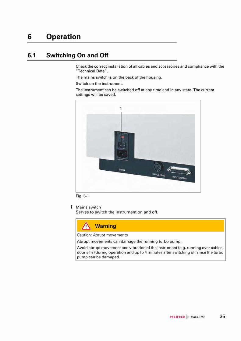
The mains switch is on the back of the housing.
Switch on the instrument.
The instrument can be switched off at any time and in any state. The current settings will be saved.
1 Mains switchServes to switch the instrument on and off.
Fig. 6-1
WarningCaution: Abrupt movements
Abrupt movements can damage the running turbo pump.
Avoid abrupt movement and vibration of the instrument (e.g. running over cables, door sills) during operation and up to 4 minutes after switching off since the turbo pump can be damaged.
35
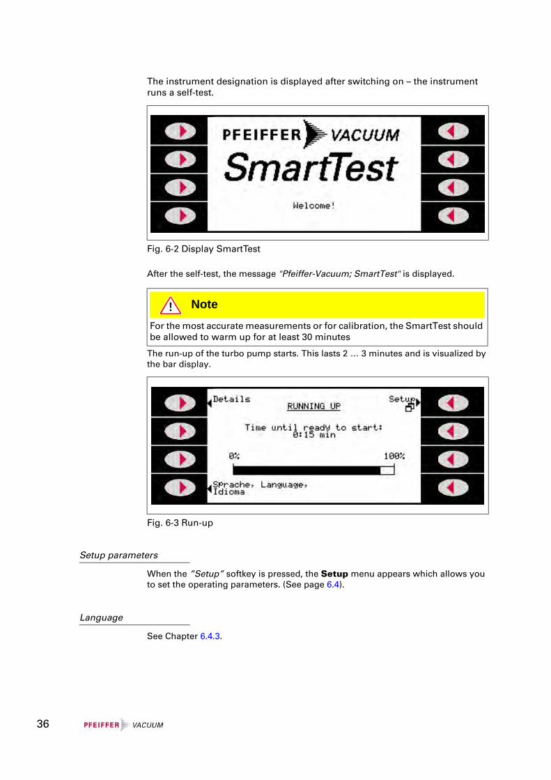
The instrument designation is displayed after switching on – the instrument runs a self-test.
After the self-test, the message "Pfeiffer-Vacuum; SmartTest" is displayed.
The run-up of the turbo pump starts. This lasts 2 … 3 minutes and is visualized by the bar display.
Setup parameters
When the ”Setup” softkey is pressed, the Setup menu appears which allows you to set the operating parameters. (See page 6.4).
Language
See Chapter 6.4.3.
Fig. 6-2 Display SmartTest
NoteFor the most accurate measurements or for calibration, the SmartTest should be allowed to warm up for at least 30 minutes
Fig. 6-3 Run-up
36
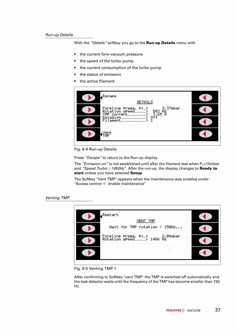
Run-up Details
With the ”Details” softkey you go to the Run-up Details menu with
• the current fore-vacuum pressure
• the speed of the turbo pump
• the current consumption of the turbo pump
• the status of emission
• the active filament
Press ”Escape” to return to the Run-up display.
The ”Emission on” is not established until after the filament test when P1<10mbar and ”Speed Turbo ≥ 1450Hz”. After the run-up, the display changes to Ready to start unless you have selected Setup.
The Softkey "Vent TMP" appears when the maintenance was enabled under "Access control enable maintenance"
Venting TMP
After confirming to Softkey "vent TMP" the TMP is switched off automatically and the leak detector waits until the frequency of the TMP has become smaller than 150 Hz.
Fig. 6-4 Run-up Details
Fig. 6-5 Venting TMP 1
37
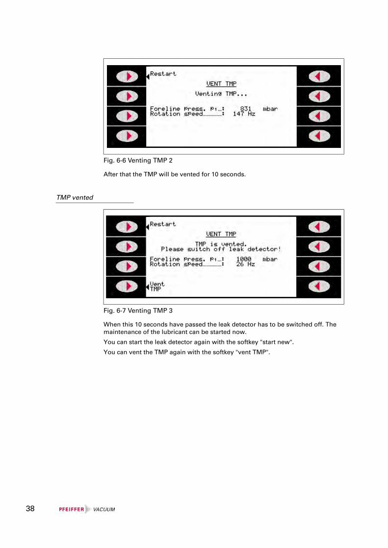
After that the TMP will be vented for 10 seconds.
TMP vented
When this 10 seconds have passed the leak detector has to be switched off. The maintenance of the lubricant can be started now.
You can start the leak detector again with the softkey "start new".
You can vent the TMP again with the softkey "vent TMP".
Fig. 6-6 Venting TMP 2
Fig. 6-7 Venting TMP 3
38
6.2 Ready to start
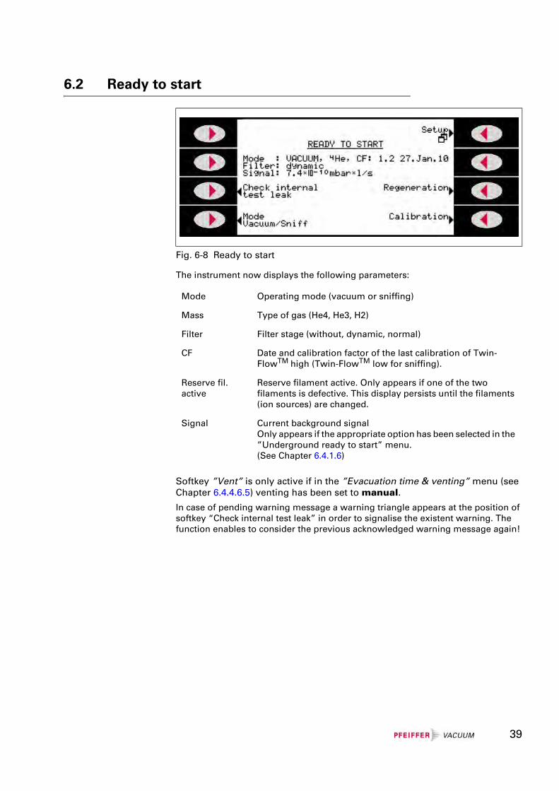
The instrument now displays the following parameters:
Softkey ”Vent” is only active if in the ”Evacuation time & venting” menu (see Chapter 6.4.4.6.5) venting has been set to manual.
In case of pending warning message a warning triangle appears at the position of softkey “Check internal test leak” in order to signalise the existent warning. The function enables to consider the previous acknowledged warning message again!
Fig. 6-8 Ready to start
Mode Operating mode (vacuum or sniffing)
Mass Type of gas (He4, He3, H2)
Filter Filter stage (without, dynamic, normal)
CF Date and calibration factor of the last calibration of Twin-FlowTM high (Twin-FlowTM low for sniffing).
Reserve fil. active
Reserve filament active. Only appears if one of the two filaments is defective. This display persists until the filaments (ion sources) are changed.
Signal Current background signalOnly appears if the appropriate option has been selected in the ”Underground ready to start” menu.(See Chapter 6.4.1.6)
39
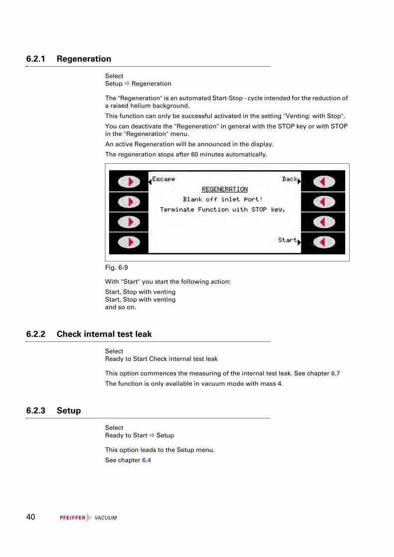
6.2.1 Regeneration
SelectSetup Regeneration
The "Regeneration" is an automated Start-Stop - cycle intended for the reduction of a raised helium background.
This function can only be successful activated in the setting "Venting: with Stop".
You can deactivate the "Regeneration" in general with the STOP key or with STOP in the "Regeneration" menu.
An active Regeneration will be announced in the display.
The regeneration stops after 60 minutes automatically.
With "Start" you start the following action:
Start, Stop with ventingStart, Stop with ventingand so on.
6.2.2 Check internal test leak
SelectReady to Start Check internal test leak
This option commences the measuring of the internal test leak. See chapter 6.7
The function is only available in vacuum mode with mass 4.
6.2.3 Setup
SelectReady to Start Setup
This option leads to the Setup menu.
See chapter 6.4
Fig. 6-9
40
6.2.4 Calibration
This function is only shown if the calibration is enabled in the Access Control mode (see Chapter 6.4.2.3).
Select Ready to Start Calibration
This option commences the calibration routine. See chapter 6.5 or 6.6, respectively.
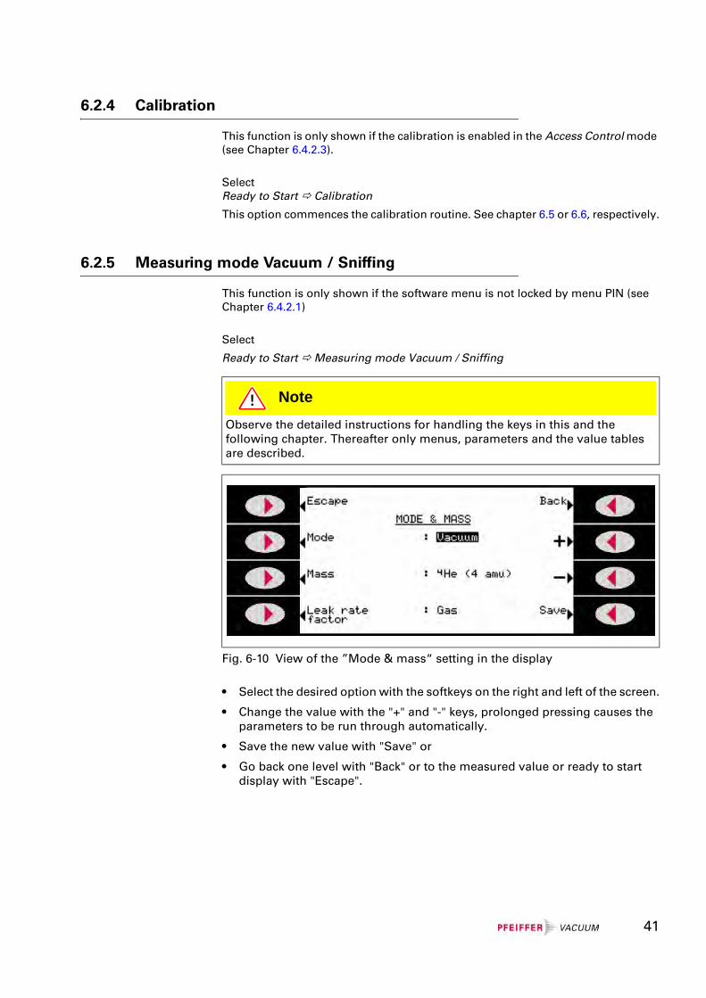
6.2.5 Measuring mode Vacuum / Sniffing
This function is only shown if the software menu is not locked by menu PIN (see Chapter 6.4.2.1)
Select
Ready to Start Measuring mode Vacuum / Sniffing
• Select the desired option with the softkeys on the right and left of the screen.
• Change the value with the "+" and "-" keys, prolonged pressing causes the parameters to be run through automatically.
• Save the new value with "Save" or
• Go back one level with "Back" or to the measured value or ready to start display with "Escape".
NoteObserve the detailed instructions for handling the keys in this and the following chapter. Thereafter only menus, parameters and the value tables are described.
Fig. 6-10 View of the ”Mode & mass“ setting in the display
41
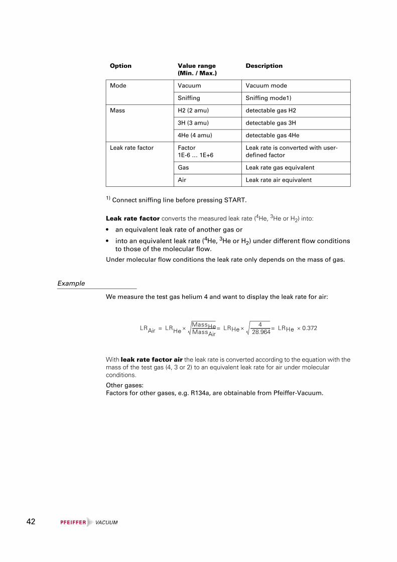
1) Connect sniffing line before pressing START.
Leak rate factor converts the measured leak rate (4He, 3He or H2) into:
• an equivalent leak rate of another gas or
• into an equivalent leak rate (4He, 3He or H2) under different flow conditions to those of the molecular flow.
Under molecular flow conditions the leak rate only depends on the mass of gas.
Example
We measure the test gas helium 4 and want to display the leak rate for air:
With leak rate factor air the leak rate is converted according to the equation with the mass of the test gas (4, 3 or 2) to an equivalent leak rate for air under molecular conditions.
Other gases:Factors for other gases, e.g. R134a, are obtainable from Pfeiffer-Vacuum.
Option Value range(Min. / Max.)
Description
Mode Vacuum Vacuum mode
Sniffing Sniffing mode1)
Mass H2 (2 amu) detectable gas H2
3H (3 amu) detectable gas 3H
4He (4 amu) detectable gas 4He
Leak rate factor Factor1E-6 … 1E+6
Leak rate is converted with user-defined factor
Gas Leak rate gas equivalent
Air Leak rate air equivalent
LRAir LRHeMassHeMassAir----------------------------× LRHe
4 28.964------------------------× LRHe 0.372×===
42
6.3 Measure
6.3.1 Measure with a test item
The instrument is ready to detect leaks as soon as it displays Ready to start:
• Select the desired measuring mode
Mode: Vacuum or Sniffing
• Check whether the parameters displayed in the Start menu are applicable.
6.3.1.1 Vacuum mode
Remove the blank flange from the inlet port and connect the test item.
Press the START / STOP button of the operating unit to start the measurement.
The test item will be evacuated and the pressure displayed during the pumping process.
After achieving the pressure for the measurement the measured value display appears (chapter 6.3.2) and starting with an appropriate background signal (<1E-09 mbarl/s) the test item can be charged with helium.
The leak rate of the test item will be shown in the display.
Press the START / STOP button again to stop the measurement.
The SmartTest goes back into Ready to Start; the test item will be vented and can be removed from the inlet port.
6.3.1.2 Sniffing mode
Seal the inlet port with a blank flange and connect the optional sniffing probe LP 5xx. See chapter 5.3.1.
Press the START / STOP button of the operating unit to start the measurement.
The leak rate in the now shown measured value display should adjust to <5E-06 mbarl/s (helium fraction of the air).
The helium charged test item can now be leak checked with the sniffing probe.
The appropriate leak rate of the test item will be shown in the display.
Press the START/STOP button again to stop the measurement.
The SmartTest goes back into Ready to Start and the test item will be vented.
STOP Danger
Risk of injury due to sucking connection flange.
If the Vacuum-Mode of the SmartTest is activated, the connection flange may suck bodily parts around the connection flange.
Keep bodily parts off the connection flange.
43
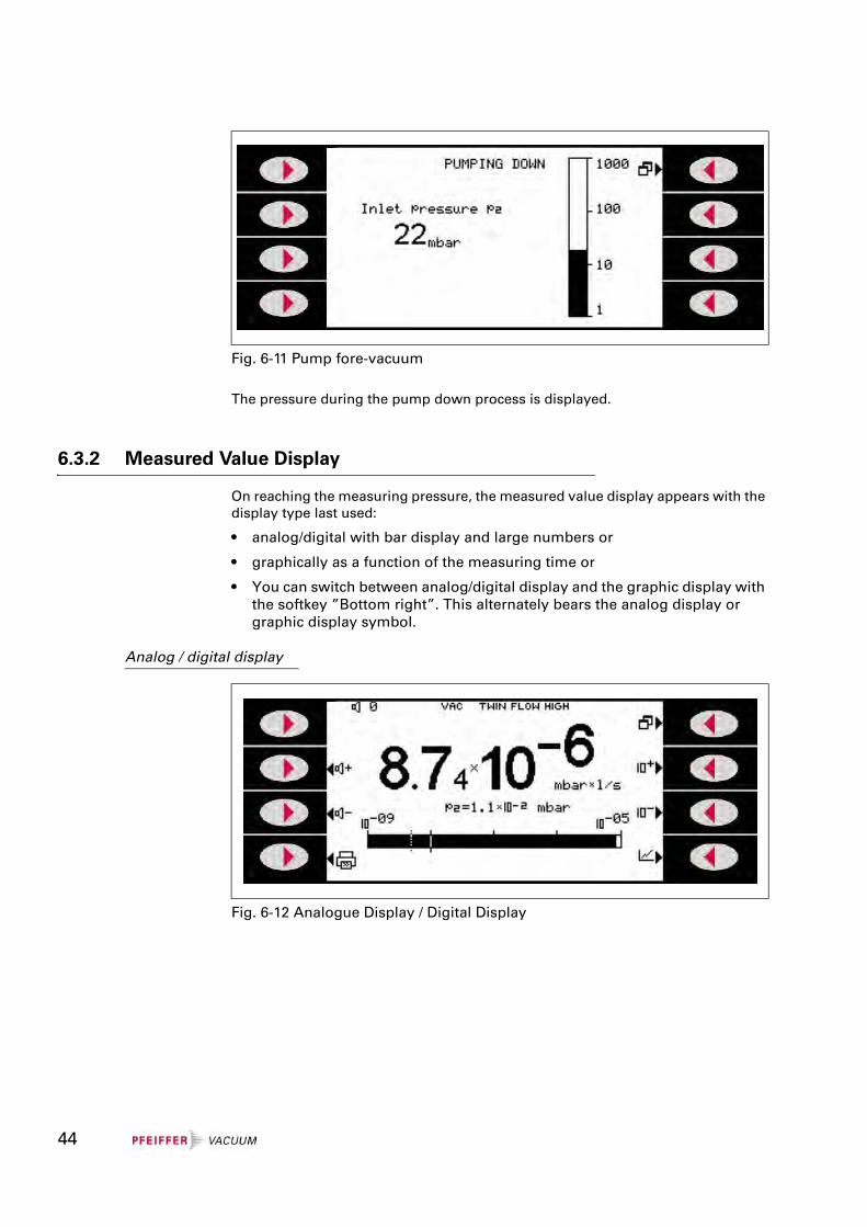
The pressure during the pump down process is displayed.
6.3.2 Measured Value Display
On reaching the measuring pressure, the measured value display appears with the display type last used:
• analog/digital with bar display and large numbers or
• graphically as a function of the measuring time or
• You can switch between analog/digital display and the graphic display with the softkey ”Bottom right”. This alternately bears the analog display or graphic display symbol.
Analog / digital display
Fig. 6-11 Pump fore-vacuum
Fig. 6-12 Analogue Display / Digital Display
44
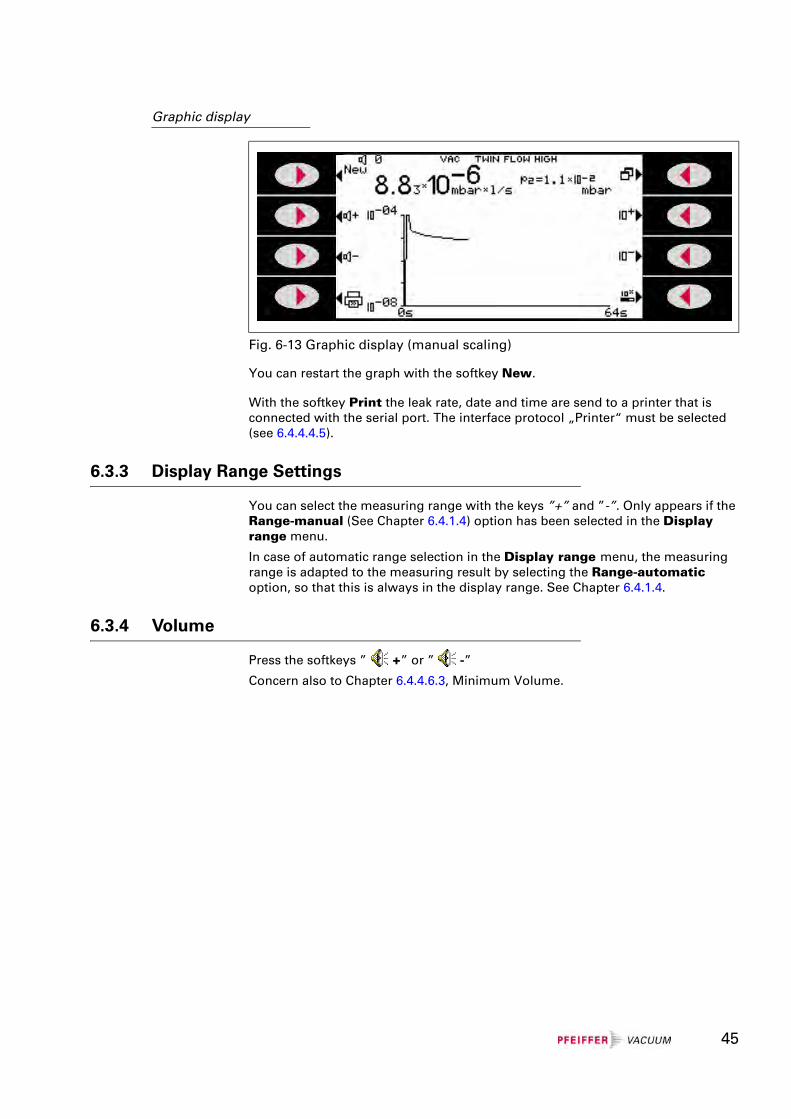
Graphic display
You can restart the graph with the softkey New.
With the softkey Print the leak rate, date and time are send to a printer that is connected with the serial port. The interface protocol „Printer“ must be selected (see 6.4.4.4.5).
6.3.3 Display Range Settings
You can select the measuring range with the keys ”+” and ”-”. Only appears if the Range-manual (See Chapter 6.4.1.4) option has been selected in the Display range menu.
In case of automatic range selection in the Display range menu, the measuring range is adapted to the measuring result by selecting the Range-automatic option, so that this is always in the display range. See Chapter 6.4.1.4.
6.3.4 Volume
Press the softkeys ” +” or ” -”
Concern also to Chapter 6.4.4.6.3, Minimum Volume.
Fig. 6-13 Graphic display (manual scaling)
45
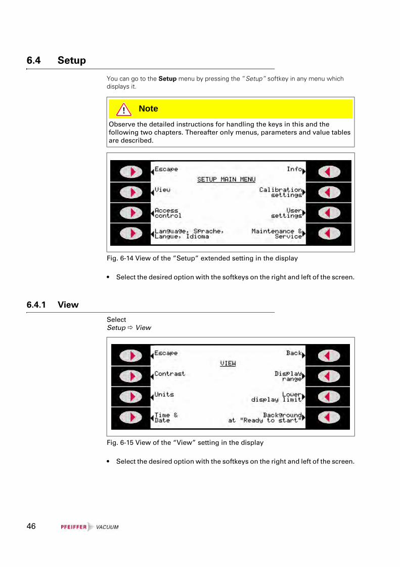
6.4 Setup
You can go to the Setup menu by pressing the ”Setup” softkey in any menu which displays it.
• Select the desired option with the softkeys on the right and left of the screen.
6.4.1 View
SelectSetup View
• Select the desired option with the softkeys on the right and left of the screen.
NoteObserve the detailed instructions for handling the keys in this and the following two chapters. Thereafter only menus, parameters and value tables are described.
Fig. 6-14 View of the ”Setup” extended setting in the display
Fig. 6-15 View of the “View” setting in the display
46
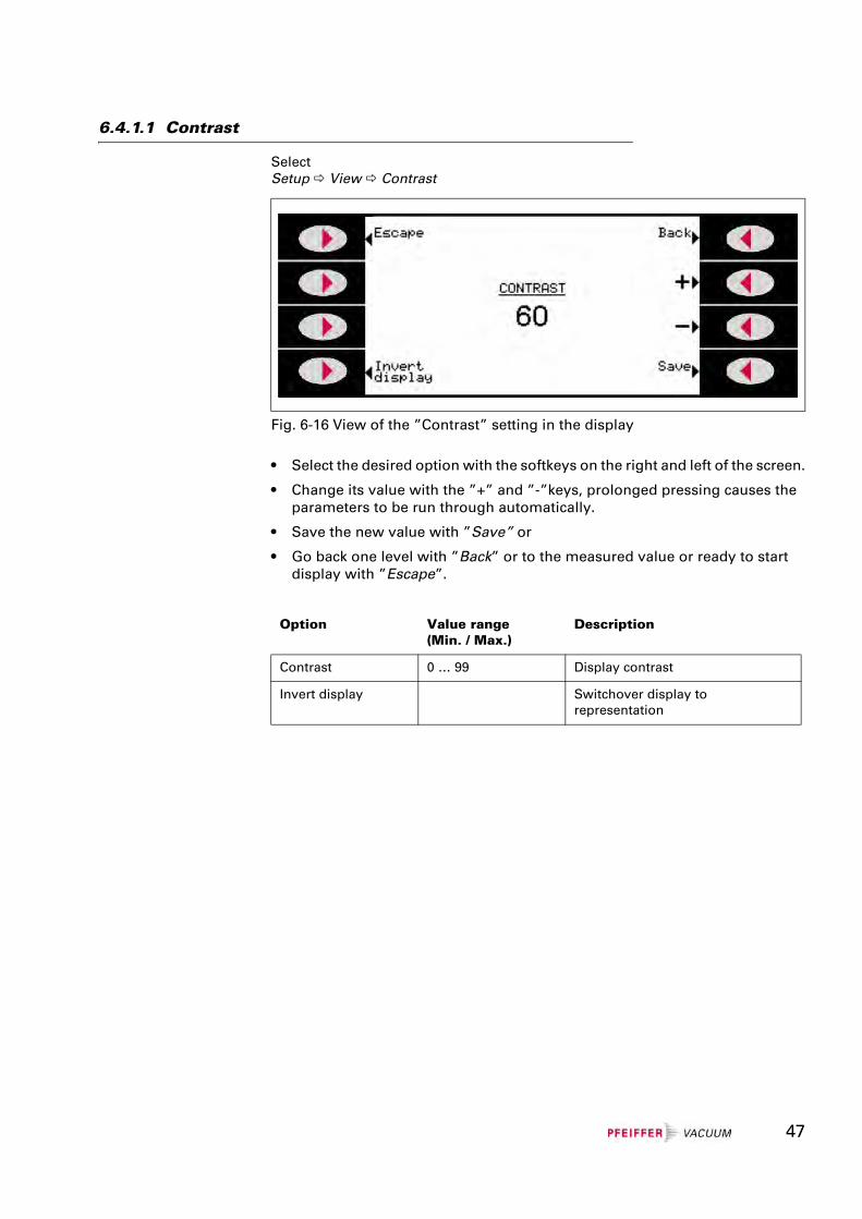
6.4.1.1 Contrast
SelectSetup View Contrast
• Select the desired option with the softkeys on the right and left of the screen.
• Change its value with the ”+” and ”-”keys, prolonged pressing causes the parameters to be run through automatically.
• Save the new value with ”Save” or
• Go back one level with ”Back” or to the measured value or ready to start display with ”Escape”.
Fig. 6-16 View of the ”Contrast” setting in the display
Option Value range(Min. / Max.)
Description
Contrast 0 … 99 Display contrast
Invert display Switchover display to representation
47
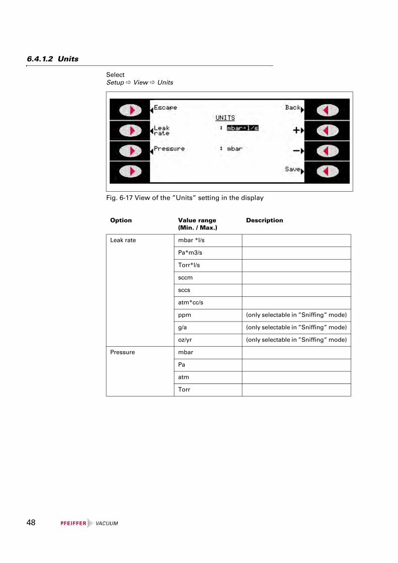
6.4.1.2 Units
SelectSetup View Units
Fig. 6-17 View of the ”Units” setting in the display
Option Value range(Min. / Max.)
Description
Leak rate mbar *l/s
Pa*m3/s
Torr*l/s
sccm
sccs
atm*cc/s
ppm (only selectable in ”Sniffing” mode)
g/a (only selectable in ”Sniffing” mode)
oz/yr (only selectable in ”Sniffing” mode)
Pressure mbar
Pa
atm
Torr
48
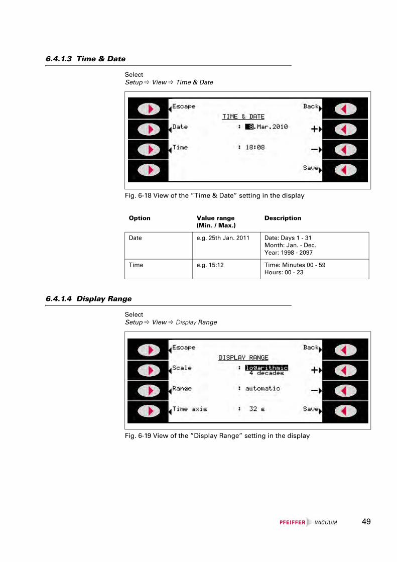
6.4.1.3 Time & Date
SelectSetup View Time & Date
6.4.1.4 Display Range
SelectSetup View Display Range
Fig. 6-18 View of the ”Time & Date” setting in the display
Option Value range(Min. / Max.)
Description
Date e.g. 25th Jan. 2011 Date: Days 1 - 31Month: Jan. - Dec.Year: 1998 - 2097
Time e.g. 15:12 Time: Minutes 00 - 59Hours: 00 - 23
Fig. 6-19 View of the ”Display Range” setting in the display
49
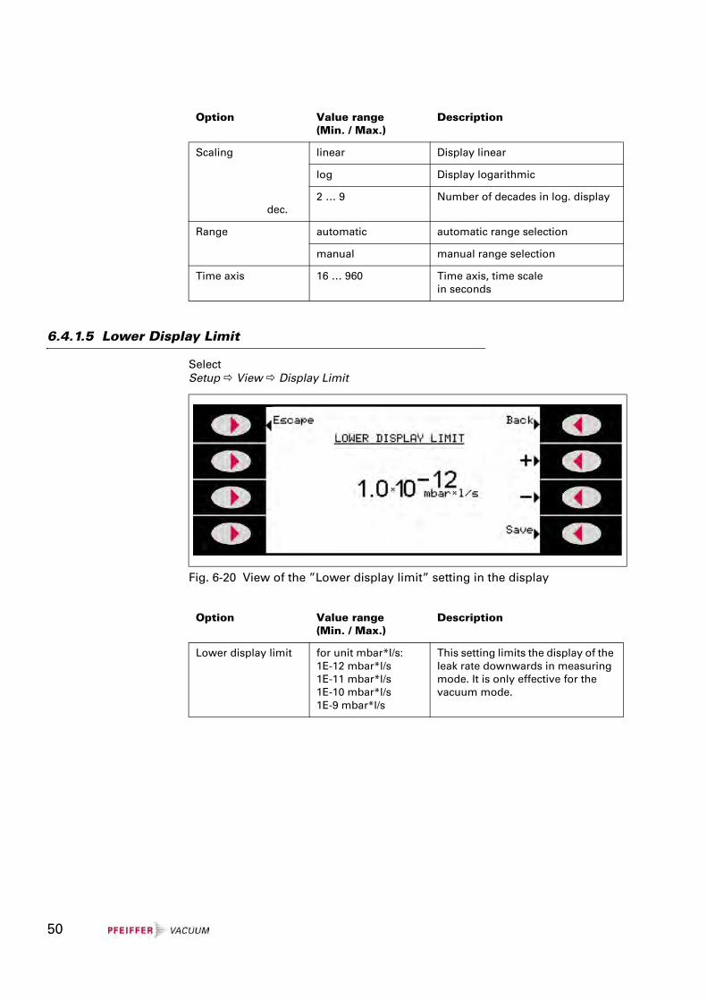
6.4.1.5 Lower Display Limit
SelectSetup View Display Limit
Option Value range(Min. / Max.)
Description
Scaling
dec.
linear Display linear
log Display logarithmic
2 … 9 Number of decades in log. display
Range automatic automatic range selection
manual manual range selection
Time axis 16 … 960 Time axis, time scalein seconds
Fig. 6-20 View of the ”Lower display limit” setting in the display
Option Value range(Min. / Max.)
Description
Lower display limit for unit mbar*l/s:1E-12 mbar*l/s1E-11 mbar*l/s1E-10 mbar*l/s1E-9 mbar*l/s
This setting limits the display of the leak rate downwards in measuring mode. It is only effective for the vacuum mode.
50
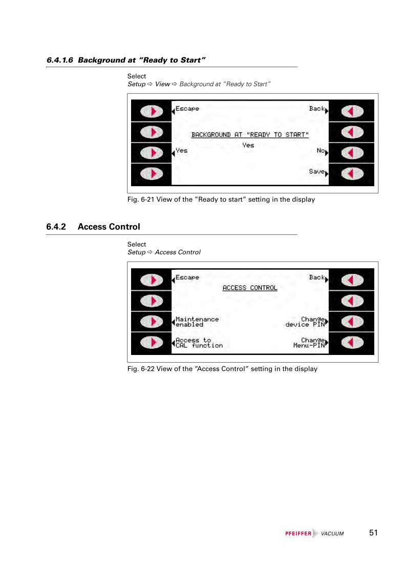
6.4.1.6 Background at “Ready to Start”
SelectSetup View Background at “Ready to Start”
6.4.2 Access Control
SelectSetup Access Control
Fig. 6-21 View of the ”Ready to start” setting in the display
Fig. 6-22 View of the ”Access Control” setting in the display
51
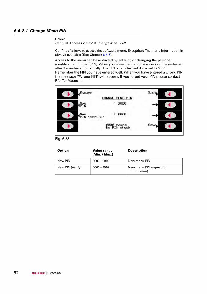
6.4.2.1 Change Menu-PIN
SelectSetup Access Control Change Menu PIN
Confines / allows to access the software menu. Exception: The menu Information is always available (See Chapter 6.4.6).
Access to the menu can be restricted by entering or changing the personal identification number (PIN). When you leave the menu the access will be restricted after 2 minutes automatically. The PIN is not checked if it is set to 0000.Remember the PIN you have entered well. When you have entered a wrong PIN the message “Wrong PIN” will appear. If you forget your PIN please contact Pfeiffer Vacuum.
Fig. 6-23
Option Value range(Min. / Max.)
Description
New PIN 0000 - 9999 New menu PIN
New PIN (verify) 0000 - 9999 New menu PIN (repeat for confirmation)
52
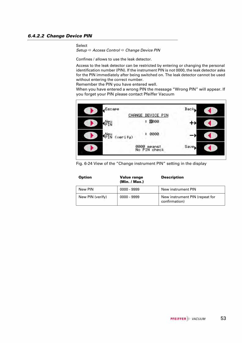
6.4.2.2 Change Device PIN
SelectSetup Access Control Change Device PIN
Confines / allows to use the leak detector.
Access to the leak detector can be restricted by entering or changing the personal identification number (PIN). If the instrument PIN is not 0000, the leak detector asks for the PIN immediately after being switched on. The leak detector cannot be used without entering the correct number.Remember the PIN you have entered well.When you have entered a wrong PIN the message “Wrong PIN” will appear. If you forget your PIN please contact Pfeiffer Vacuum
Fig. 6-24 View of the ”Change instrument PIN” setting in the display
Option Value range(Min. / Max.)
Description
New PIN 0000 - 9999 New instrument PIN
New PIN (verify) 0000 - 9999 New instrument PIN (repeat for confirmation)
53
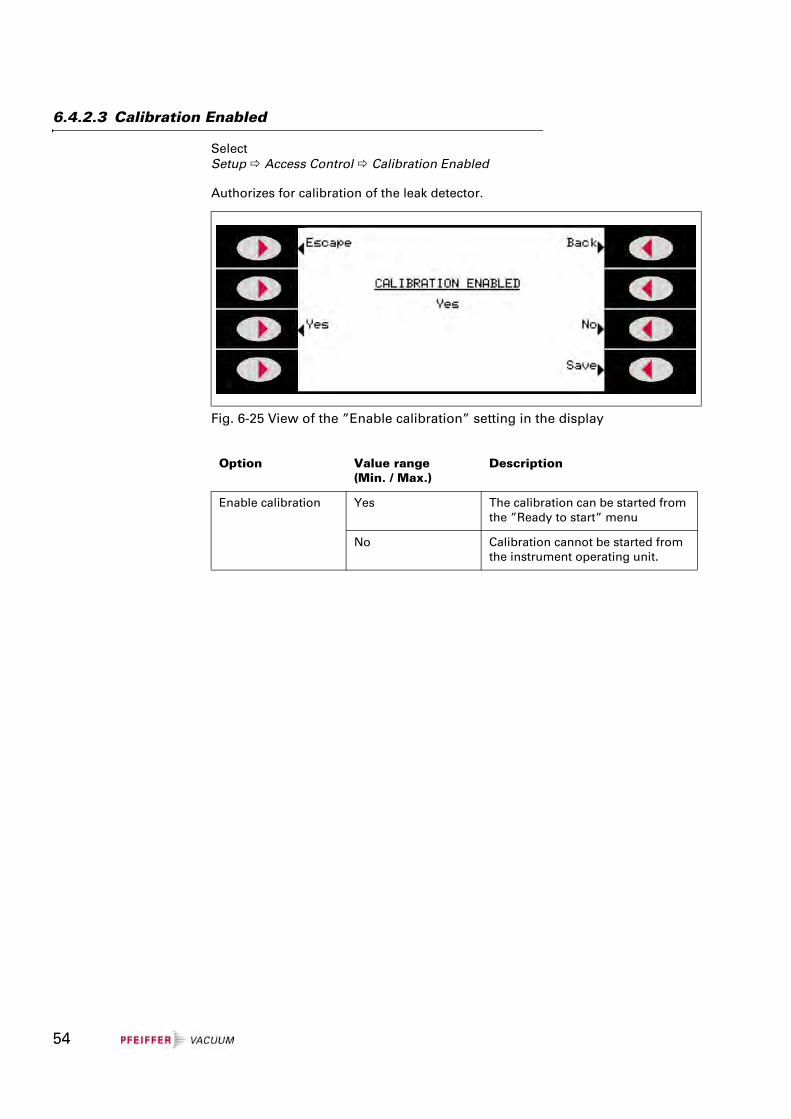
6.4.2.3 Calibration Enabled
SelectSetup Access Control Calibration Enabled
Authorizes for calibration of the leak detector.
Fig. 6-25 View of the ”Enable calibration” setting in the display
Option Value range(Min. / Max.)
Description
Enable calibration Yes The calibration can be started from the ”Ready to start” menu
No Calibration cannot be started from the instrument operating unit.
54
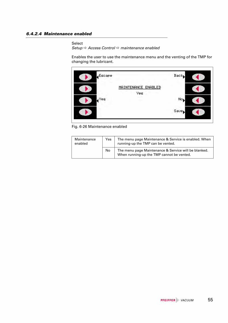
6.4.2.4 Maintenance enabled
SelectSetup Access Control maintenance enabled
Enables the user to use the maintenance menu and the venting of the TMP for changing the lubricant.
Fig. 6-26 Maintenance enabled
Maintenanceenabled
Yes The menu page Maintenance & Service is enabled. When running-up the TMP can be vented.
No The menu page Maintenance & Service will be blanked. When running-up the TMP cannot be vented.
55
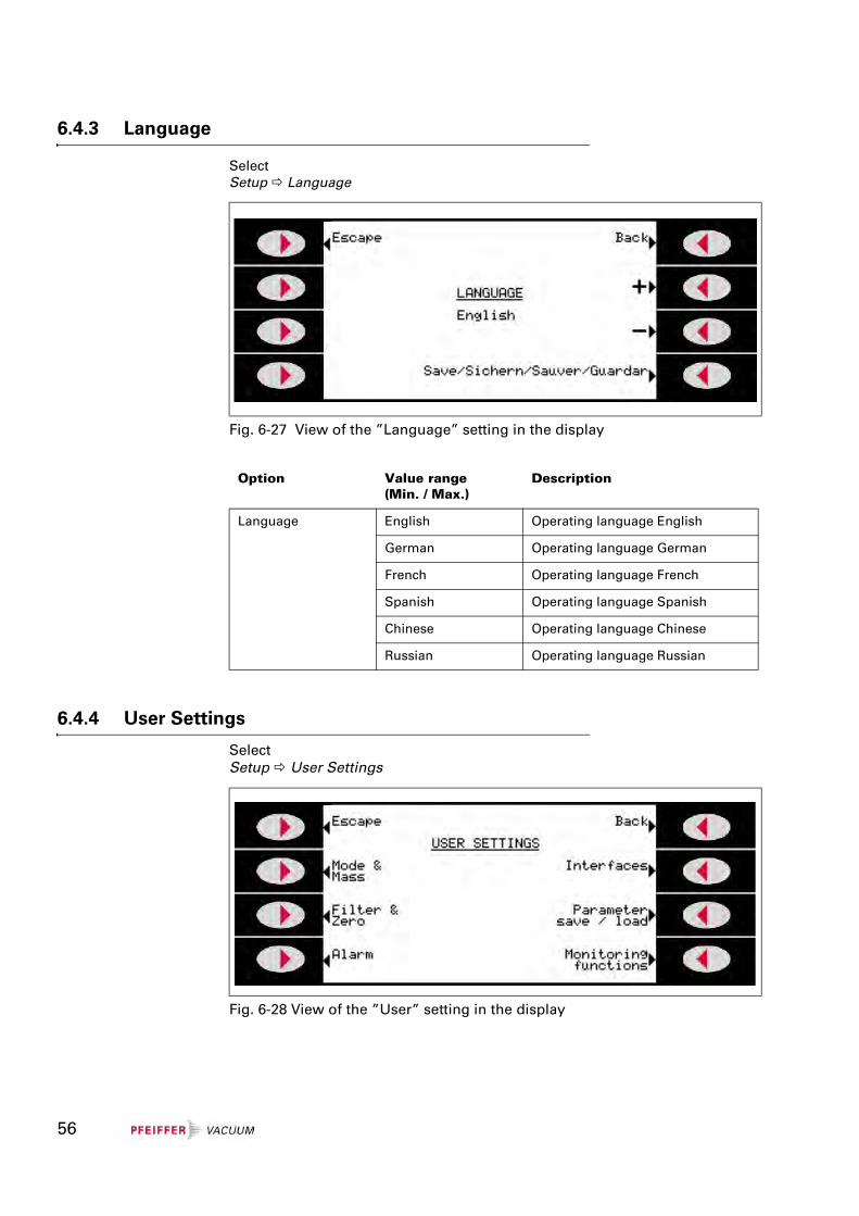
6.4.3 Language
Select Setup Language
6.4.4 User Settings
SelectSetup User Settings
Fig. 6-27 View of the ”Language” setting in the display
Option Value range(Min. / Max.)
Description
Language English Operating language English
German Operating language German
French Operating language French
Spanish Operating language Spanish
Chinese Operating language Chinese
Russian Operating language Russian
Fig. 6-28 View of the ”User” setting in the display
56
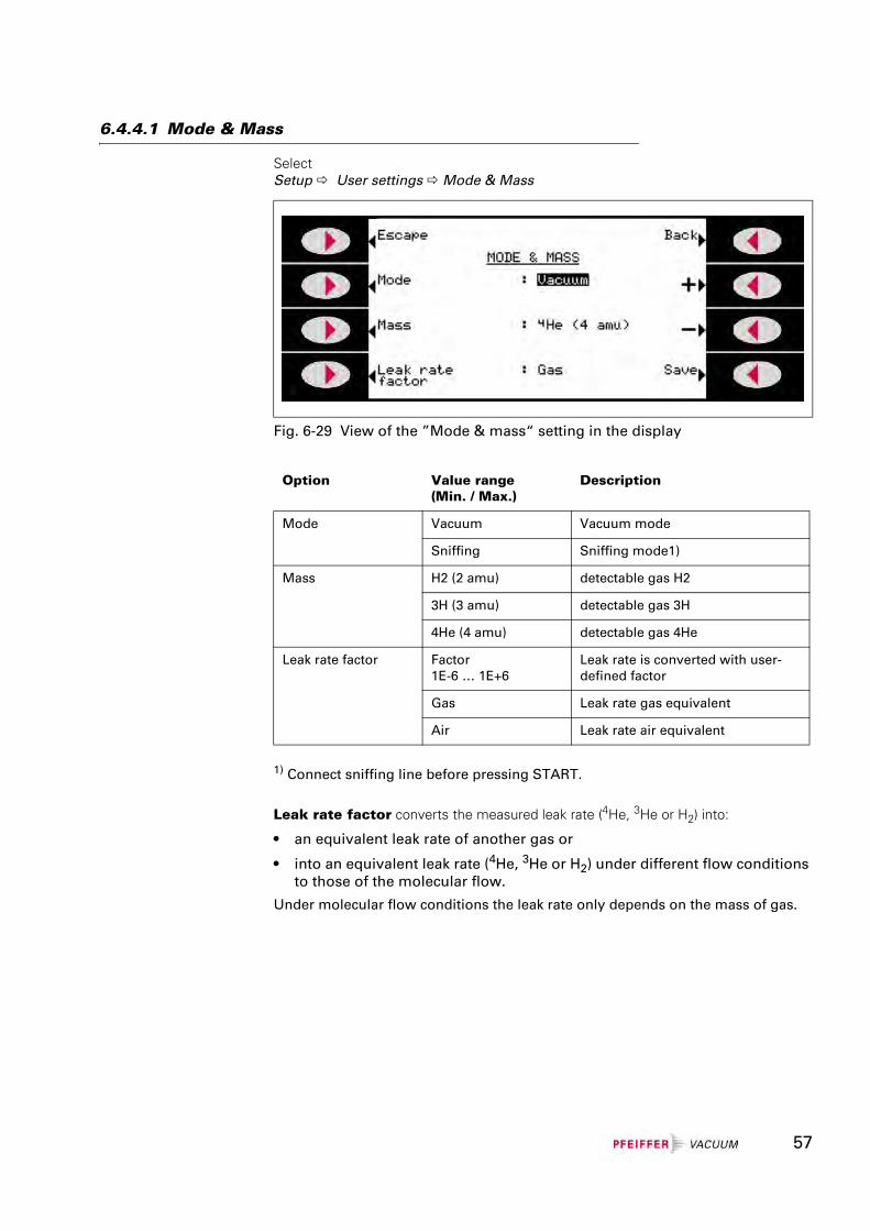
6.4.4.1 Mode & Mass
SelectSetup User settings Mode & Mass
1) Connect sniffing line before pressing START.
Leak rate factor converts the measured leak rate (4He, 3He or H2) into:
• an equivalent leak rate of another gas or
• into an equivalent leak rate (4He, 3He or H2) under different flow conditions to those of the molecular flow.
Under molecular flow conditions the leak rate only depends on the mass of gas.
Fig. 6-29 View of the ”Mode & mass“ setting in the display
Option Value range(Min. / Max.)
Description
Mode Vacuum Vacuum mode
Sniffing Sniffing mode1)
Mass H2 (2 amu) detectable gas H2
3H (3 amu) detectable gas 3H
4He (4 amu) detectable gas 4He
Leak rate factor Factor1E-6 … 1E+6
Leak rate is converted with user-defined factor
Gas Leak rate gas equivalent
Air Leak rate air equivalent
57
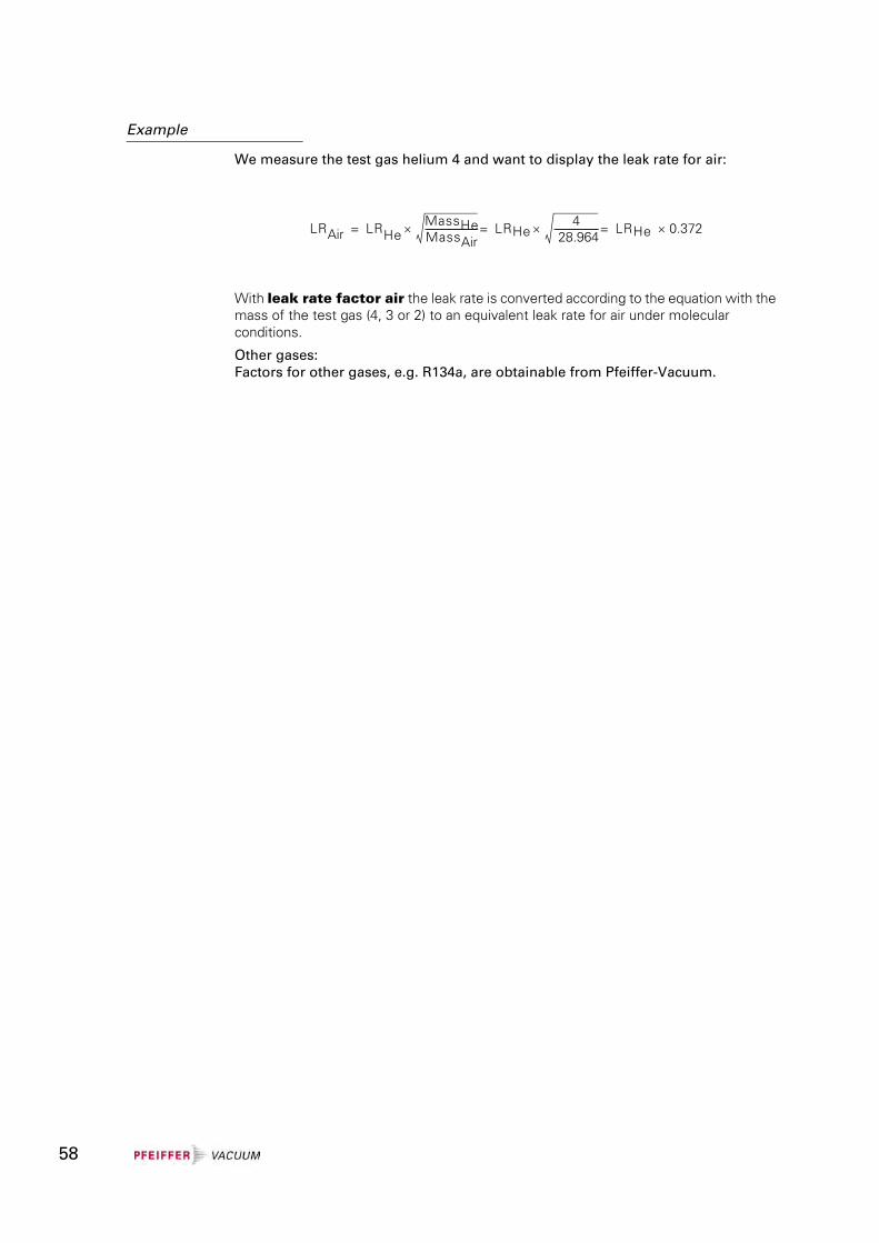
Example
We measure the test gas helium 4 and want to display the leak rate for air:
With leak rate factor air the leak rate is converted according to the equation with the mass of the test gas (4, 3 or 2) to an equivalent leak rate for air under molecular conditions.
Other gases:Factors for other gases, e.g. R134a, are obtainable from Pfeiffer-Vacuum.
LRAir LRHeMassHeMassAir----------------------------× LRHe
4 28.964------------------------× LRHe 0.372×===
58
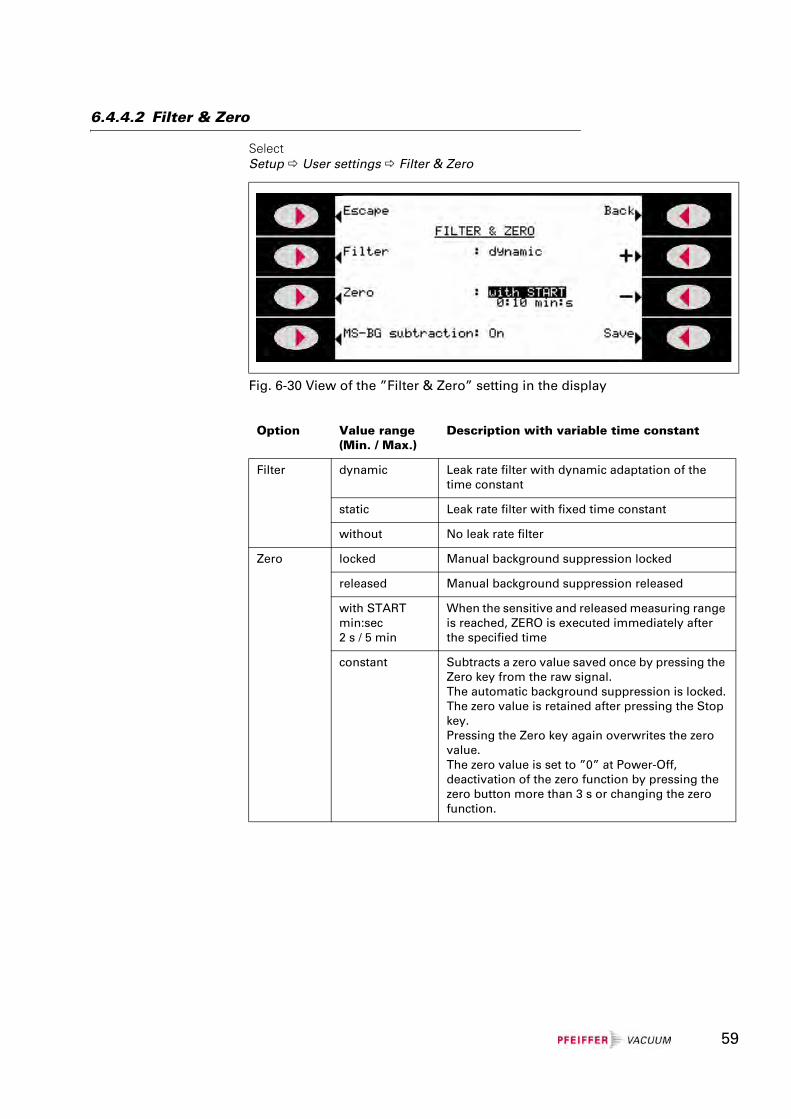
6.4.4.2 Filter & Zero
SelectSetup User settings Filter & Zero
Fig. 6-30 View of the ”Filter & Zero” setting in the display
Option Value range(Min. / Max.)
Description with variable time constant
Filter dynamic Leak rate filter with dynamic adaptation of the time constant
static Leak rate filter with fixed time constant
without No leak rate filter
Zero locked Manual background suppression locked
released Manual background suppression released
with STARTmin:sec2 s / 5 min
When the sensitive and released measuring range is reached, ZERO is executed immediately after the specified time
constant Subtracts a zero value saved once by pressing the Zero key from the raw signal.The automatic background suppression is locked.The zero value is retained after pressing the Stop key.Pressing the Zero key again overwrites the zero value.The zero value is set to ”0” at Power-Off, deactivation of the zero function by pressing the zero button more than 3 s or changing the zero function.
59
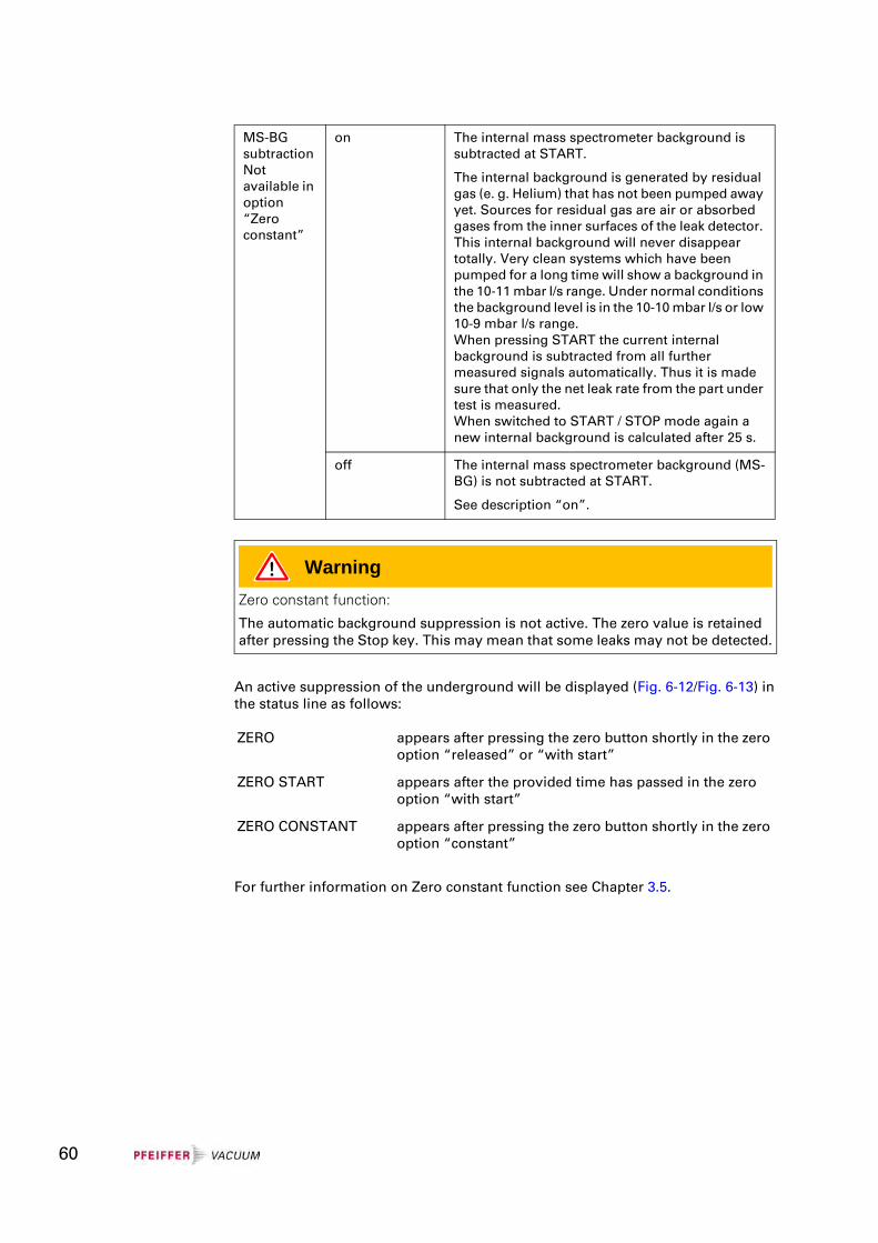
An active suppression of the underground will be displayed (Fig. 6-12/Fig. 6-13) in the status line as follows:
For further information on Zero constant function see Chapter 3.5.
MS-BG subtraction Not available in option “Zero constant”
on The internal mass spectrometer background is subtracted at START.
The internal background is generated by residual gas (e. g. Helium) that has not been pumped away yet. Sources for residual gas are air or absorbed gases from the inner surfaces of the leak detector. This internal background will never disappear totally. Very clean systems which have been pumped for a long time will show a background in the 10-11 mbar l/s range. Under normal conditions the background level is in the 10-10 mbar l/s or low 10-9 mbar l/s range.When pressing START the current internal background is subtracted from all further measured signals automatically. Thus it is made sure that only the net leak rate from the part under test is measured.When switched to START / STOP mode again a new internal background is calculated after 25 s.
off The internal mass spectrometer background (MS-BG) is not subtracted at START.
See description “on”.
WarningZero constant function:
The automatic background suppression is not active. The zero value is retained after pressing the Stop key. This may mean that some leaks may not be detected.
ZERO appears after pressing the zero button shortly in the zero option “released” or “with start”
ZERO START appears after the provided time has passed in the zero option “with start”
ZERO CONSTANT appears after pressing the zero button shortly in the zero option “constant”
60
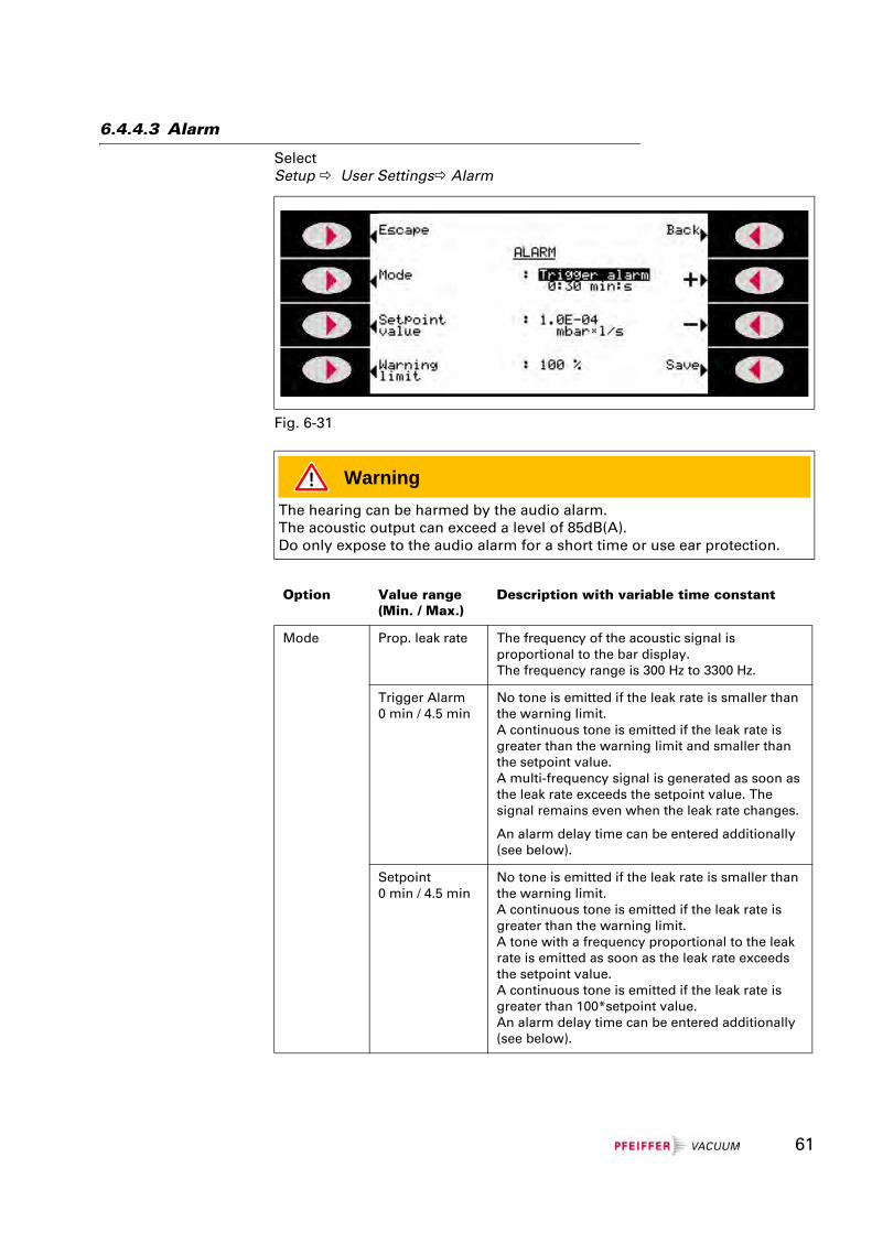
6.4.4.3 Alarm
SelectSetup User Settings Alarm
Fig. 6-31
WarningThe hearing can be harmed by the audio alarm.The acoustic output can exceed a level of 85dB(A).Do only expose to the audio alarm for a short time or use ear protection.
Option Value range(Min. / Max.)
Description with variable time constant
Mode Prop. leak rate The frequency of the acoustic signal is proportional to the bar display.The frequency range is 300 Hz to 3300 Hz.
Trigger Alarm0 min / 4.5 min
No tone is emitted if the leak rate is smaller than the warning limit.A continuous tone is emitted if the leak rate is greater than the warning limit and smaller than the setpoint value.A multi-frequency signal is generated as soon as the leak rate exceeds the setpoint value. The signal remains even when the leak rate changes.
An alarm delay time can be entered additionally (see below).
Setpoint0 min / 4.5 min
No tone is emitted if the leak rate is smaller than the warning limit.A continuous tone is emitted if the leak rate is greater than the warning limit.A tone with a frequency proportional to the leak rate is emitted as soon as the leak rate exceeds the setpoint value.A continuous tone is emitted if the leak rate is greater than 100*setpoint value.An alarm delay time can be entered additionally (see below).
61
In some applications (for example during the pump down of a ”test chamber system”) it may be necessary to suppress an alarm for some time after pressing the START key.
After pressing the START key the acoustic signal can be activated: as soon as the leak rate is lower than the warning limit or when the alarm delay has proceeded or when the type of alarm “Prop. leak rate” i.e. “Pinpoint” or the sniffer mode is adjusted.
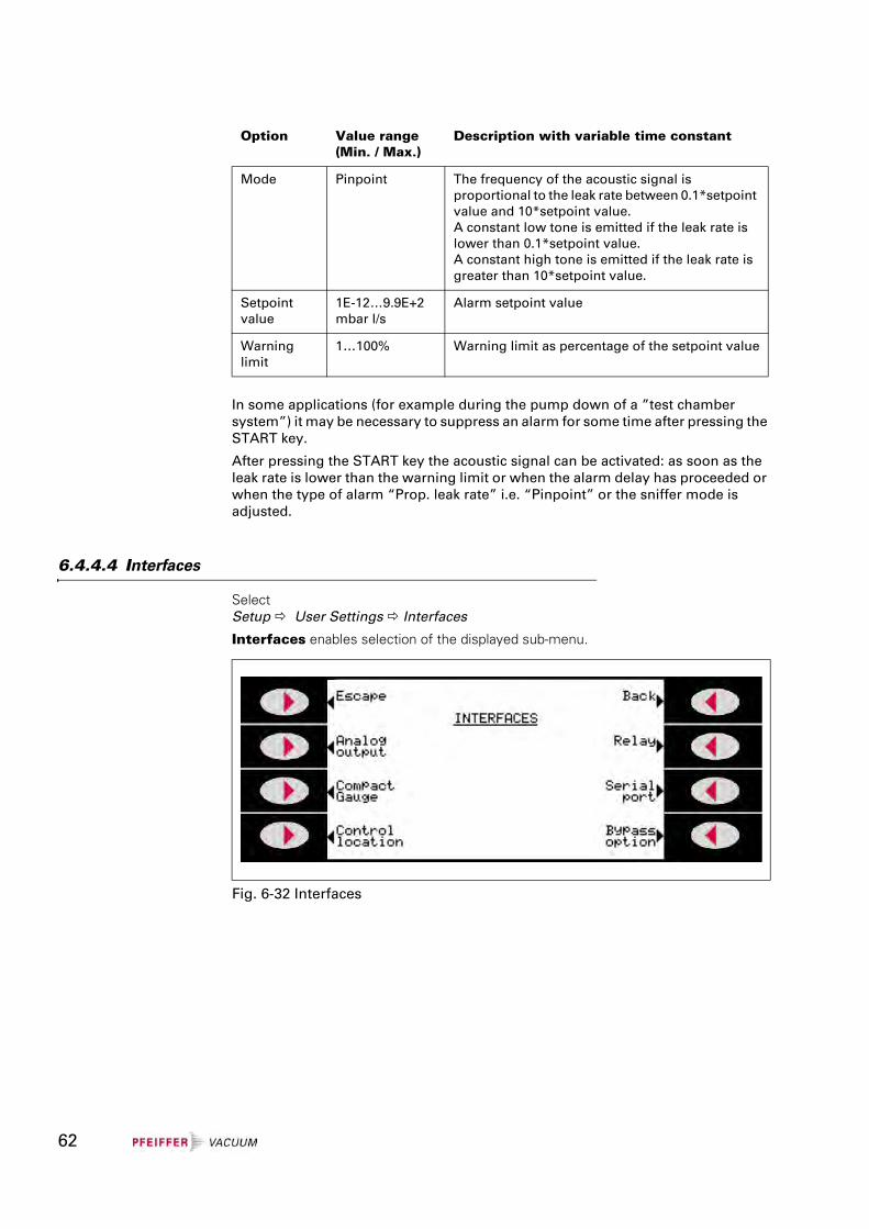
6.4.4.4 Interfaces
Select Setup User Settings Interfaces
Interfaces enables selection of the displayed sub-menu.
Mode Pinpoint The frequency of the acoustic signal is proportional to the leak rate between 0.1*setpoint value and 10*setpoint value.A constant low tone is emitted if the leak rate is lower than 0.1*setpoint value.A constant high tone is emitted if the leak rate is greater than 10*setpoint value.
Setpoint value
1E-12…9.9E+2mbar l/s
Alarm setpoint value
Warning limit
1…100% Warning limit as percentage of the setpoint value
Option Value range(Min. / Max.)
Description with variable time constant
Fig. 6-32 Interfaces
62
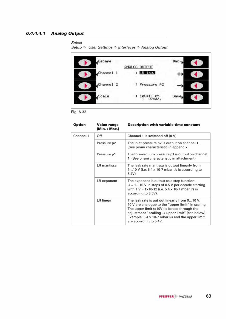
6.4.4.4.1 Analog Output
SelectSetup User Settings Interfaces Analog Output
Fig. 6-33
Option Value range(Min. / Max.)
Description with variable time constant
Channel 1 Off Channel 1 is switched off (0 V)
Pressure p2 The inlet pressure p2 is output on channel 1.(See pirani characteristic in appendix)
Pressure p1 The fore-vacuum pressure p1 is output on channel 1. (See pirani characteristic in attachment)
LR mantissa The leak rate mantissa is output linearly from 1…10 V (i.e. 5.4 x 10⁻⁷ mbar l/s is according to 5.4V)
LR exponent The exponent is output as a step function: U = 1…10 V in steps of 0.5 V per decade starting with 1 V = 1x10-12 (i.e. 5.4 x 10⁻⁷ mbar l/s is according to 3.5V).
LR linear The leak rate is put out linearly from 0…10 V.10 V are analogue to the “upper limit” in scaling. The upper limit (=10V) is forced through the adjustment “scalling → upper limit” (see below).Example: 5.4 x 10⁻⁷ mbar l/s and the upper limit are according to 5.4V.
63
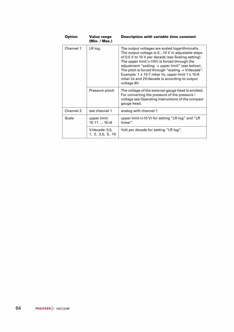
Channel 1 LR log. The output voltages are scaled logarithmically. The output voltage is 0…10 V in adjustable steps of 0.5 V to 10 V per decade (see Scaling setting). The upper limit (=10V) is forced through the adjustment “scaling → upper limit” (see below). The pitch is forced through “scaling → V/decade”. Example: 1 x 10⁻⁷ mbar l/s, upper limit 1 x 10⁻⁶ mbar l/s and 2V/decade is according to output voltage 8V.
Pressure p(ext) The voltage of the external gauge head is emitted. For converting the pressure of the pressure / voltage see Operating Instructions of the compact gauge head.
Channel 2 see channel 1 analog with channel 1
Scale upper limit:1E-11 … 1E+6
upper limit (=10 V) for setting ”LR log” and ”LR linear”.
V/decade: 0,5, 1, 2, 2,5, 5, 10
Volt per decade for setting ”LR log”.
Option Value range(Min. / Max.)
Description with variable time constant
64
6.4.4.4.2 Compact Gauge
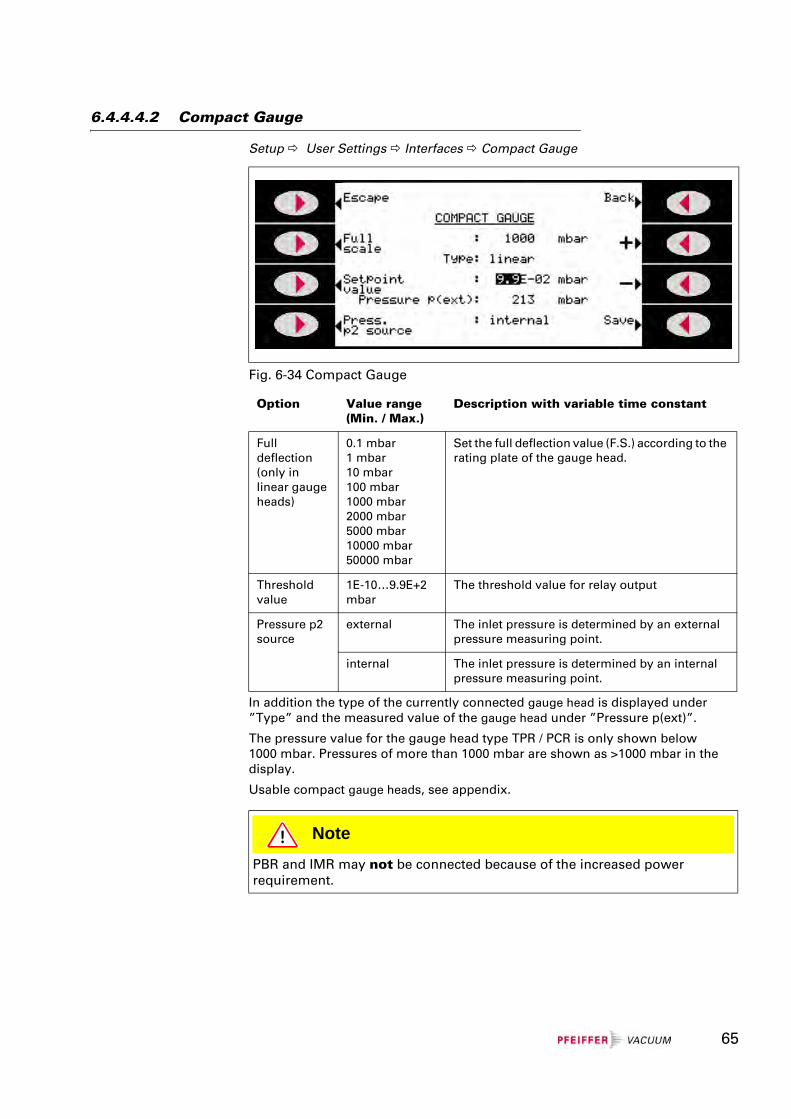
Setup User Settings Interfaces Compact Gauge
In addition the type of the currently connected gauge head is displayed under ”Type” and the measured value of the gauge head under ”Pressure p(ext)”.
The pressure value for the gauge head type TPR / PCR is only shown below 1000 mbar. Pressures of more than 1000 mbar are shown as >1000 mbar in the display.
Usable compact gauge heads, see appendix.
Fig. 6-34 Compact Gauge
Option Value range(Min. / Max.)
Description with variable time constant
Full deflection (only in linear gauge heads)
0.1 mbar1 mbar10 mbar100 mbar1000 mbar2000 mbar5000 mbar10000 mbar50000 mbar
Set the full deflection value (F.S.) according to the rating plate of the gauge head.
Threshold value
1E-10…9.9E+2 mbar
The threshold value for relay output
Pressure p2 source
external The inlet pressure is determined by an external pressure measuring point.
internal The inlet pressure is determined by an internal pressure measuring point.
NotePBR and IMR may not be connected because of the increased power requirement.
65
6.4.4.4.3 Control Location
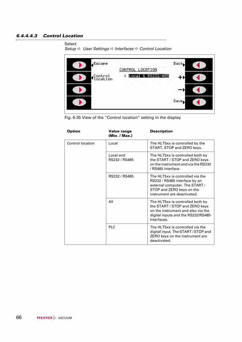
SelectSetup User Settings Interfaces Control Location
Fig. 6-35 View of the ”Control location” setting in the display
Option Value range(Min. / Max.)
Description
Control location Local The HLT5xx is controlled by the START, STOP and ZERO keys.
Local andRS232 / RS485
The HLT5xx is controlled both by the START / STOP and ZERO keys on the instrument and via the RS232 / RS485 interface.
RS232 / RS485 The HLT5xx is controlled via the RS232 / RS485 interface by an external computer. The START / STOP and ZERO keys on the instrument are deactivated.
All The HLT5xx is controlled both by the START / STOP and ZERO keys on the instrument and also via the digital inputs and the RS232/RS485-Interfaces.
PLC The HLT5xx is controlled via the digital input. The START / STOP and ZERO keys on the instrument are deactivated.
66
6.4.4.4.4 Relay
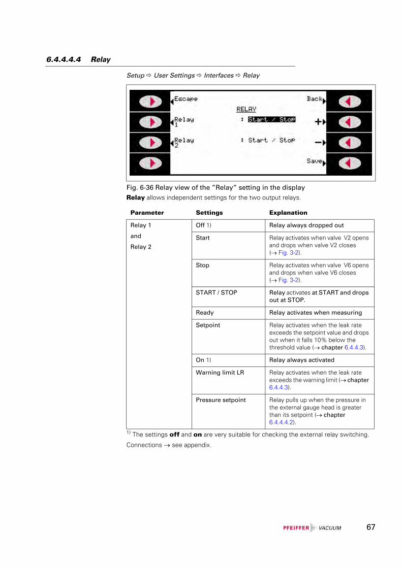
Setup User Settings Interfaces Relay
Relay allows independent settings for the two output relays.
1) The settings off and on are very suitable for checking the external relay switching.
Connections → see appendix.
Fig. 6-36 Relay view of the ”Relay” setting in the display
Parameter Settings Explanation
Relay 1
and
Relay 2
Off 1) Relay always dropped out
Start Relay activates when valve V2 opens and drops when valve V2 closes (→ Fig. 3-2).
Stop Relay activates when valve V6 opens and drops when valve V6 closes (→ Fig. 3-2).
START / STOP Relay activates at START and drops out at STOP.
Ready Relay activates when measuring
Setpoint Relay activates when the leak rate exceeds the setpoint value and drops out when it falls 10% below the threshold value (→ chapter 6.4.4.3).
On 1) Relay always activated
Warning limit LR Relay activates when the leak rate exceeds the warning limit (→ chapter 6.4.4.3).
Pressure setpoint Relay pulls up when the pressure in the external gauge head is greater than its setpoint (→ chapter 6.4.4.4.2).
67
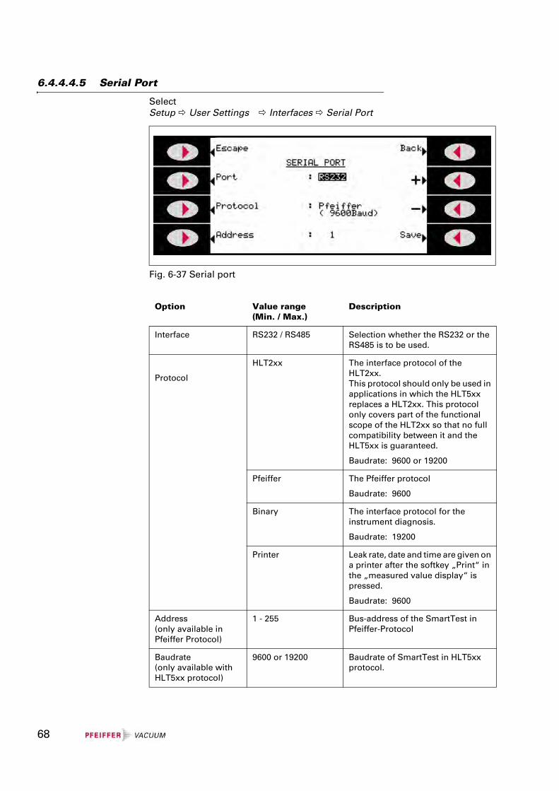
6.4.4.4.5 Serial Port
SelectSetup User Settings Interfaces Serial Port
Fig. 6-37 Serial port
Option Value range(Min. / Max.)
Description
Interface RS232 / RS485 Selection whether the RS232 or the RS485 is to be used.
Protocol
HLT2xx The interface protocol of the HLT2xx.This protocol should only be used in applications in which the HLT5xx replaces a HLT2xx. This protocol only covers part of the functional scope of the HLT2xx so that no full compatibility between it and the HLT5xx is guaranteed.
Baudrate: 9600 or 19200
Pfeiffer The Pfeiffer protocol
Baudrate: 9600
Binary The interface protocol for the instrument diagnosis.
Baudrate: 19200
Printer Leak rate, date and time are given on a printer after the softkey „Print“ in the „measured value display“ is pressed.
Baudrate: 9600
Address (only available in Pfeiffer Protocol)
1 - 255 Bus-address of the SmartTest in Pfeiffer-Protocol
Baudrate(only available with HLT5xx protocol)
9600 or 19200 Baudrate of SmartTest in HLT5xx protocol.
68
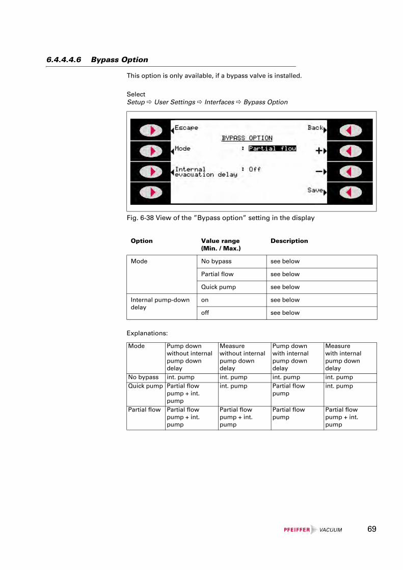
6.4.4.4.6 Bypass Option
This option is only available, if a bypass valve is installed.
SelectSetup User Settings Interfaces Bypass Option
Explanations:
Fig. 6-38 View of the ”Bypass option” setting in the display
Option Value range(Min. / Max.)
Description
Mode No bypass see below
Partial flow see below
Quick pump see below
Internal pump-down delay
on see below
off see below
Mode Pump downwithout internal pump down delay
Measurewithout internal pump down delay
Pump downwith internal pump down delay
Measurewith internal pump down delay
No bypass int. pump int. pump int. pump int. pumpQuick pump Partial flow
pump + int. pump
int. pump Partial flow pump
int. pump
Partial flow Partial flow pump + int. pump
Partial flow pump + int. pump
Partial flow pump
Partial flow pump + int. pump
69
6.4.4.5 Parameter save / load
SelectSetup User settings Parameter save / load
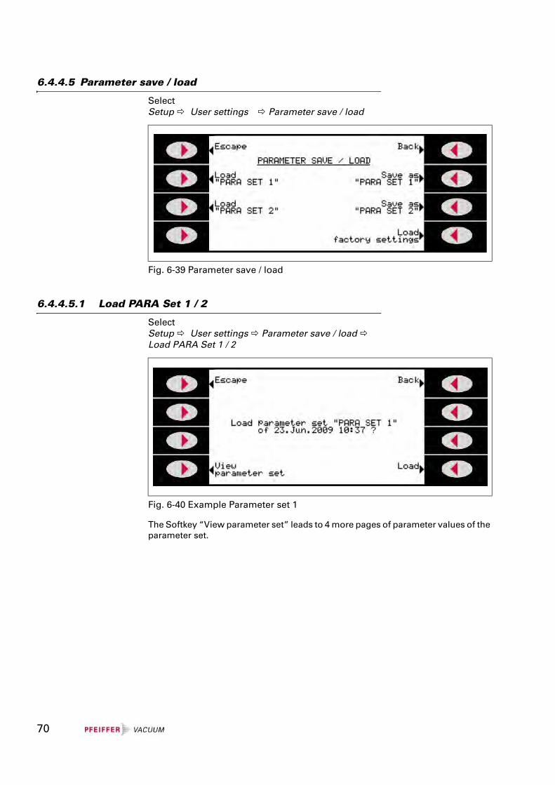
6.4.4.5.1 Load PARA Set 1 / 2
SelectSetup User settings Parameter save / load Load PARA Set 1 / 2
The Softkey “View parameter set” leads to 4 more pages of parameter values of the parameter set.
Fig. 6-39 Parameter save / load
Fig. 6-40 Example Parameter set 1
70
6.4.4.5.2 Load Factory Settings
SelectSetup User Settings Parameter save / load Load Factory Settings
List of default parameter see appendix.
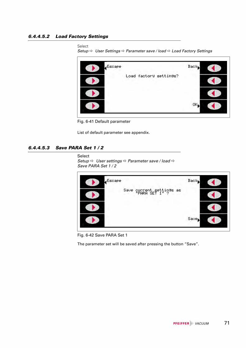
6.4.4.5.3 Save PARA Set 1 / 2
SelectSetup User settings Parameter save / load Save PARA Set 1 / 2
The parameter set will be saved after pressing the button “Save”.
Fig. 6-41 Default parameter
Fig. 6-42 Save PARA Set 1
71
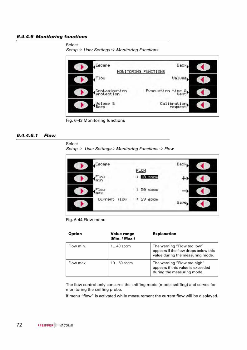
6.4.4.6 Monitoring functions
SelectSetup User Settings Monitoring Functions
6.4.4.6.1 Flow
SelectSetup User Settings Monitoring Functions Flow
The flow control only concerns the sniffing mode (mode: sniffing) and serves for monitoring the sniffing probe.
If menu “flow” is activated while measurement the current flow will be displayed.
Fig. 6-43 Monitoring functions
Fig. 6-44 Flow menu
Option Value range(Min. / Max.)
Explanation
Flow min. 1…40 sccm The warning ”Flow too low” appears if the flow drops below this value during the measuring mode.
Flow max. 10…50 sccm The warning ”Flow too high” appears if this value is exceeded during the measuring mode.
72
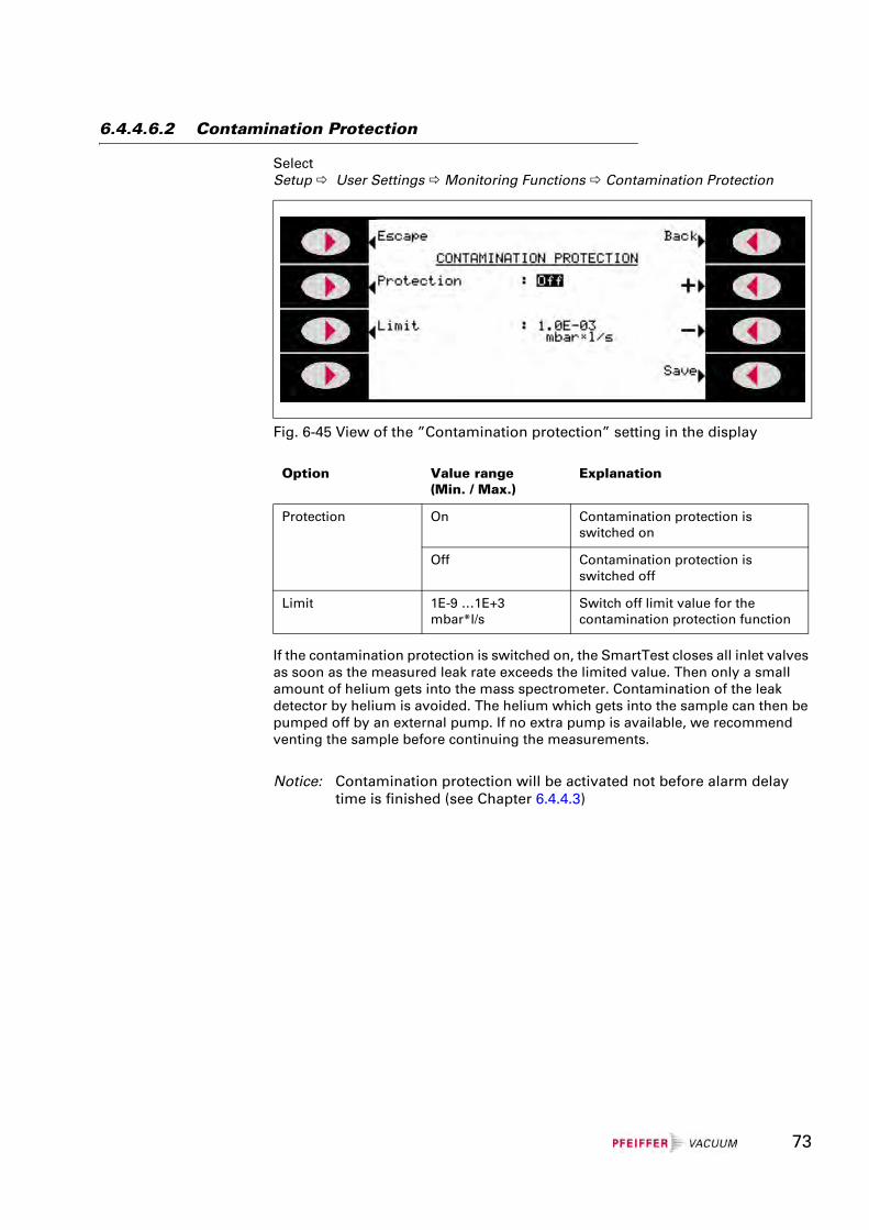
6.4.4.6.2 Contamination Protection
SelectSetup User Settings Monitoring Functions Contamination Protection
If the contamination protection is switched on, the SmartTest closes all inlet valves as soon as the measured leak rate exceeds the limited value. Then only a small amount of helium gets into the mass spectrometer. Contamination of the leak detector by helium is avoided. The helium which gets into the sample can then be pumped off by an external pump. If no extra pump is available, we recommend venting the sample before continuing the measurements.
Notice: Contamination protection will be activated not before alarm delay time is finished (see Chapter 6.4.4.3)
Fig. 6-45 View of the ”Contamination protection” setting in the display
Option Value range(Min. / Max.)
Explanation
Protection On Contamination protection is switched on
Off Contamination protection is switched off
Limit 1E-9 …1E+3mbar*l/s
Switch off limit value for the contamination protection function
73
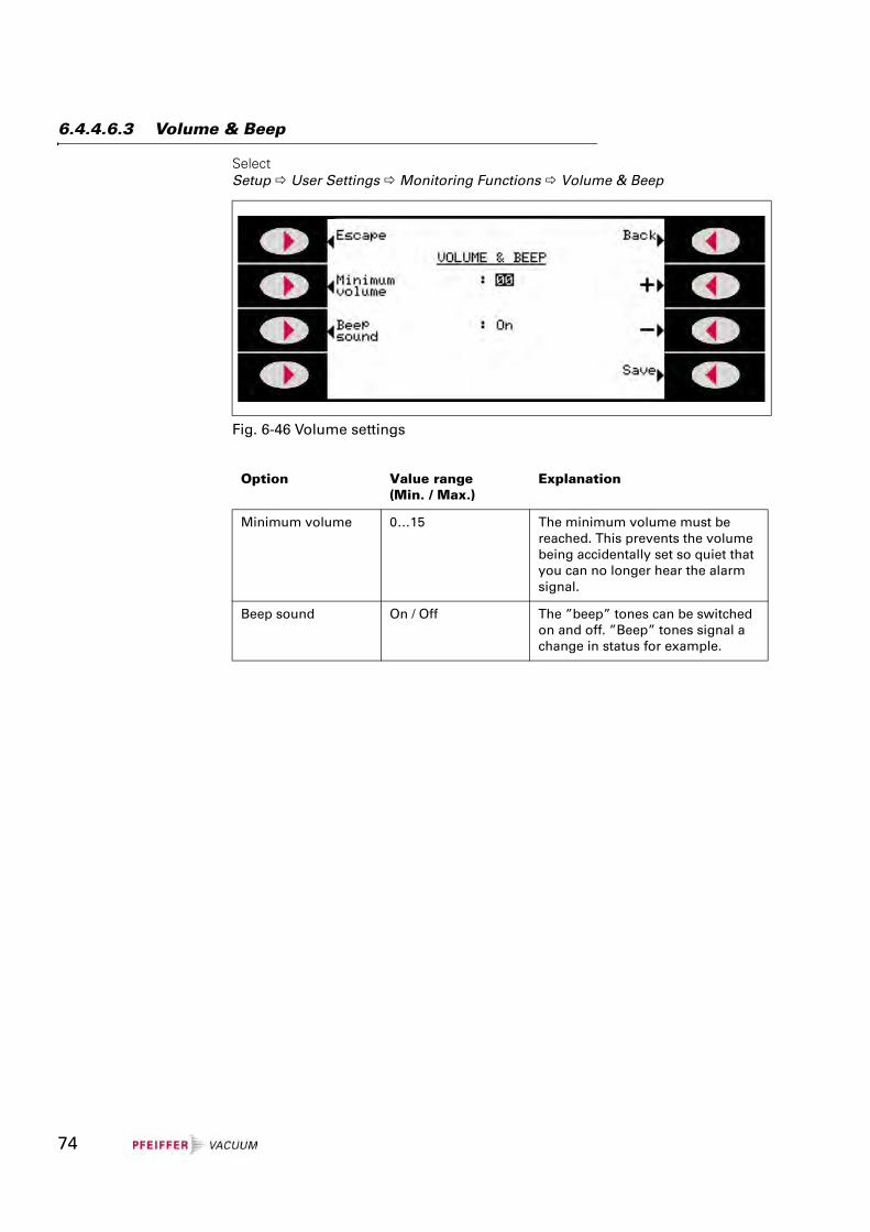
6.4.4.6.3 Volume & Beep
Select Setup User Settings Monitoring Functions Volume & Beep
Fig. 6-46 Volume settings
Option Value range(Min. / Max.)
Explanation
Minimum volume 0…15 The minimum volume must be reached. This prevents the volume being accidentally set so quiet that you can no longer hear the alarm signal.
Beep sound On / Off The ”beep” tones can be switched on and off. ”Beep” tones signal a change in status for example.
74
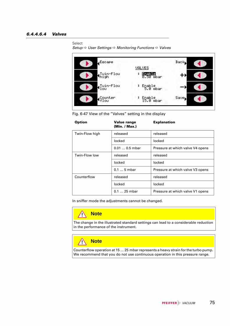
6.4.4.6.4 Valves
Select Setup User Settings Monitoring Functions Valves
In sniffer mode the adjustments cannot be changed.
Fig. 6-47 View of the ”Valves” setting in the display
Option Value range(Min. / Max.)
Explanation
Twin-Flow high released released
locked locked
0.01 … 0.5 mbar Pressure at which valve V4 opens
Twin-Flow low released released
locked locked
0.1 … 5 mbar Pressure at which valve V3 opens
Counterflow released released
locked locked
0.1 … 25 mbar Pressure at which valve V1 opens
NoteThe change in the illustrated standard settings can lead to a considerable reduction in the performance of the instrument.
NoteCounterflow operation at 15 … 25 mbar represents a heavy strain for the turbo pump. We recommend that you do not use continuous operation in this pressure range.
75
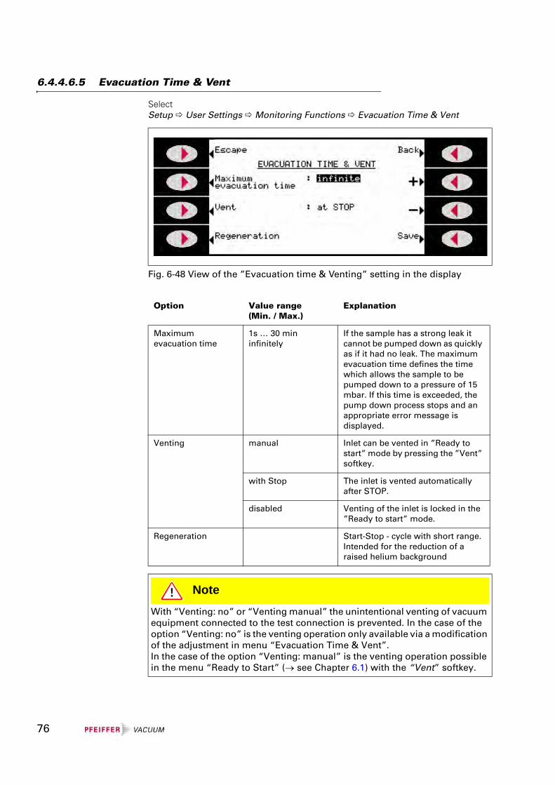
6.4.4.6.5 Evacuation Time & Vent
Select Setup User Settings Monitoring Functions Evacuation Time & Vent
Fig. 6-48 View of the ”Evacuation time & Venting” setting in the display
Option Value range(Min. / Max.)
Explanation
Maximum evacuation time
1s … 30 mininfinitely
If the sample has a strong leak it cannot be pumped down as quickly as if it had no leak. The maximum evacuation time defines the time which allows the sample to be pumped down to a pressure of 15 mbar. If this time is exceeded, the pump down process stops and an appropriate error message is displayed.
Venting manual Inlet can be vented in ”Ready to start” mode by pressing the ”Vent” softkey.
with Stop The inlet is vented automatically after STOP.
disabled Venting of the inlet is locked in the ”Ready to start” mode.
Regeneration Start-Stop - cycle with short range. Intended for the reduction of a raised helium background
NoteWith “Venting: no” or “Venting manual” the unintentional venting of vacuum equipment connected to the test connection is prevented. In the case of the option “Venting: no” is the venting operation only available via a modification of the adjustment in menu “Evacuation Time & Vent”.In the case of the option “Venting: manual” is the venting operation possible in the menu “Ready to Start” (→ see Chapter 6.1) with the “Vent” softkey.
76
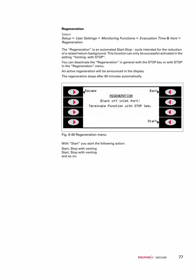
Regeneration
Select Setup User Settings Monitoring Functions Evacuation Time & Vent Regeneration
The “Regeneration” is an automated Start-Stop - cycle intended for the reduction of a raised helium background. This function can only be successful activated in the setting “Venting: with STOP”.
You can deactivate the “Regeneration” in general with the STOP key or with STOP in the “Regeneration” menu.
An active regeneration will be announced in the display.
The regeneration stops after 60 minutes automatically.
With “Start” you start the following action:
Start, Stop with ventingStart, Stop with ventingand so on.
Fig. 6-49 Regeneration menu
77
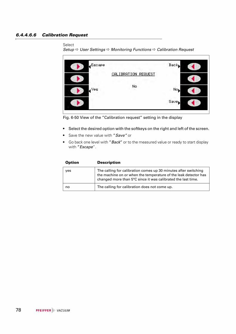
6.4.4.6.6 Calibration Request
Select Setup User Settings Monitoring Functions Calibration Request
• Select the desired option with the softkeys on the right and left of the screen.
• Save the new value with ”Save” or
• Go back one level with ”Back” or to the measured value or ready to start display with ”Escape”.
Fig. 6-50 View of the ”Calibration request” setting in the display
Option Description
yes The calling for calibration comes up 30 minutes after switching the machine on or when the temperature of the leak detector has changed more than 5°C since it was calibrated the last time.
no The calling for calibration does not come up.
78
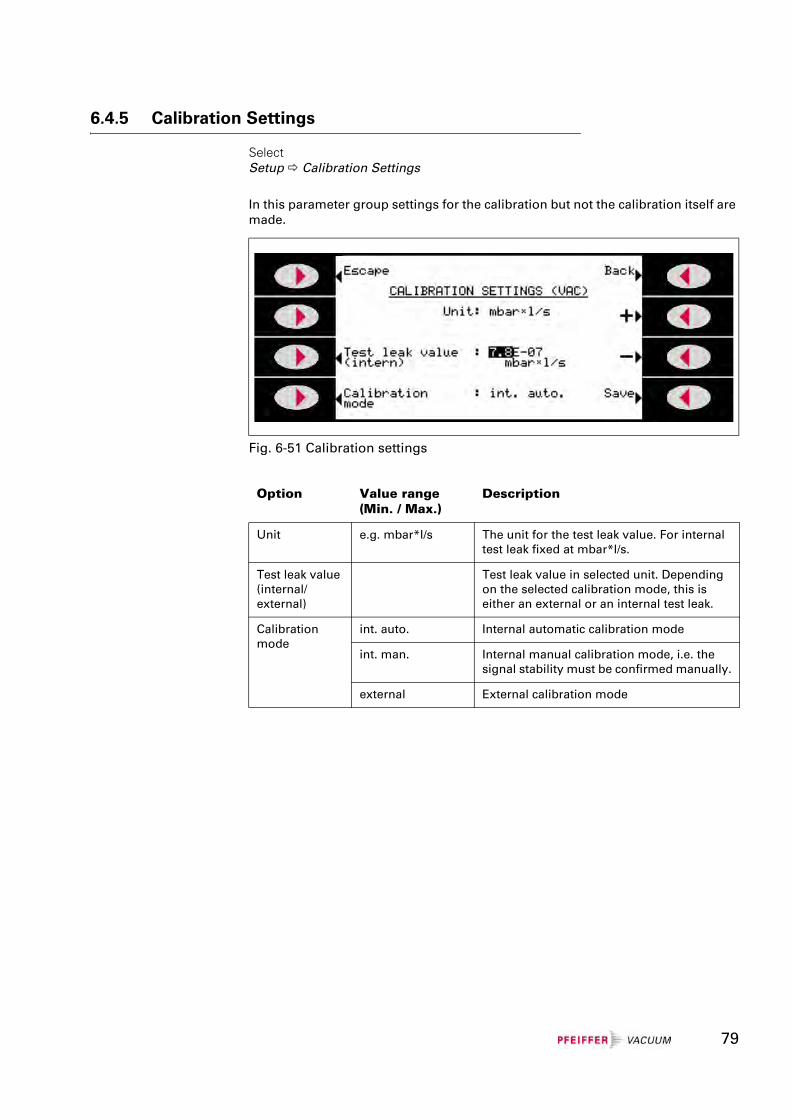
6.4.5 Calibration Settings
Select Setup Calibration Settings
In this parameter group settings for the calibration but not the calibration itself are made.
Fig. 6-51 Calibration settings
Option Value range(Min. / Max.)
Description
Unit e.g. mbar*l/s The unit for the test leak value. For internal test leak fixed at mbar*l/s.
Test leak value (internal/external)
Test leak value in selected unit. Depending on the selected calibration mode, this is either an external or an internal test leak.
Calibration mode
int. auto. Internal automatic calibration mode
int. man. Internal manual calibration mode, i.e. the signal stability must be confirmed manually.
external External calibration mode
79
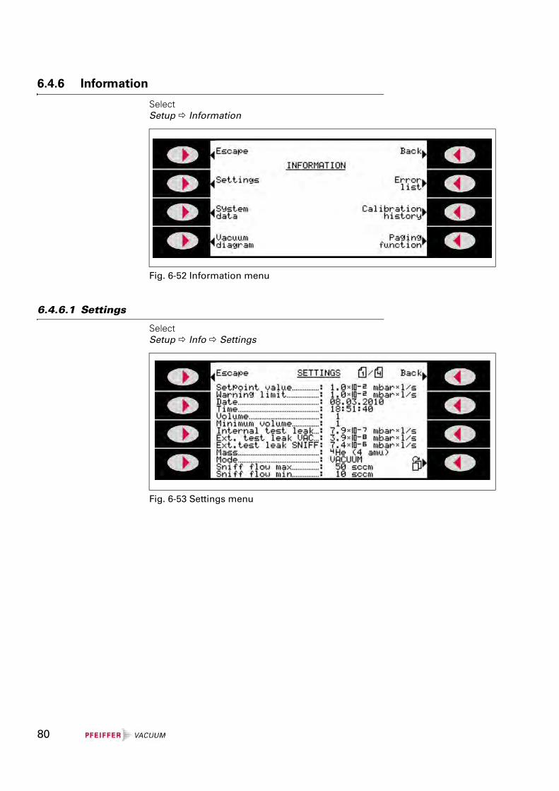
6.4.6 Information
Select Setup Information
6.4.6.1 Settings
Select Setup Info Settings
Fig. 6-52 Information menu
Fig. 6-53 Settings menu
80
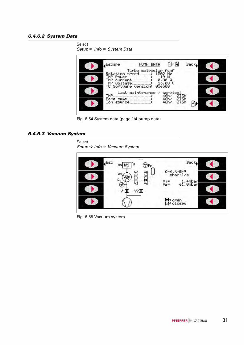
6.4.6.2 System Data
Select Setup Info System Data
6.4.6.3 Vacuum System
Select Setup Info Vacuum System
Fig. 6-54 System data (page 1/4 pump data)
Fig. 6-55 Vacuum system
81
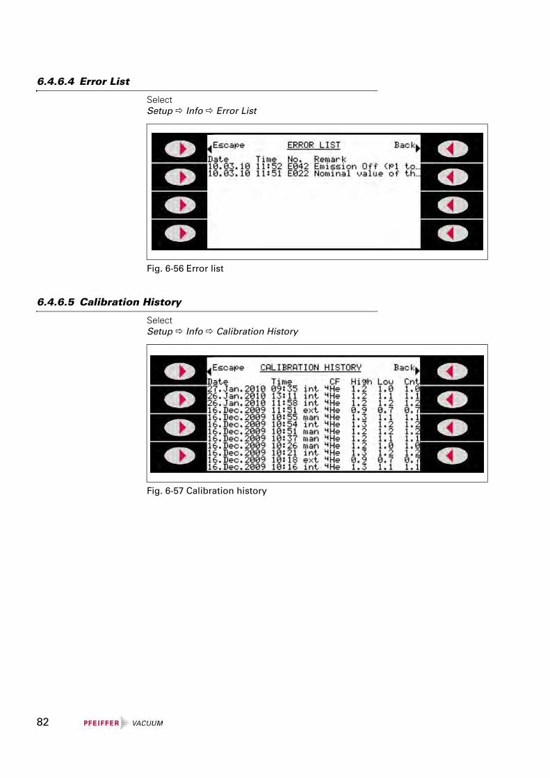
6.4.6.4 Error List
Select Setup Info Error List
6.4.6.5 Calibration History
Select Setup Info Calibration History
Fig. 6-56 Error list
Fig. 6-57 Calibration history
82
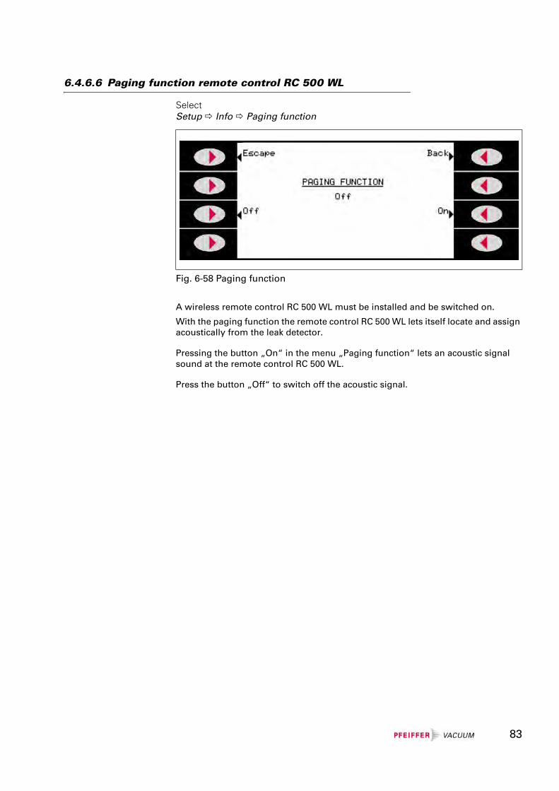
6.4.6.6 Paging function remote control RC 500 WL
Select Setup Info Paging function
A wireless remote control RC 500 WL must be installed and be switched on.
With the paging function the remote control RC 500 WL lets itself locate and assign acoustically from the leak detector.
Pressing the button „On“ in the menu „Paging function“ lets an acoustic signal sound at the remote control RC 500 WL.
Press the button „Off“ to switch off the acoustic signal.
Fig. 6-58 Paging function
83
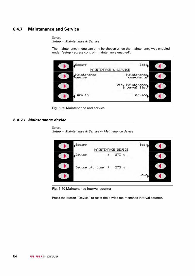
6.4.7 Maintenance and Service
Select Setup Maintenance & Service
The maintenance menu can only be chosen when the maintenance was enabled under "setup - access control - maintenance enabled".
6.4.7.1 Maintenance device
Select Setup Maintenance & Service Maintenance device
Press the button “Device” to reset the device maintenance interval counter.
Fig. 6-59 Maintenance and service
Fig. 6-60 Maintenance interval counter
84
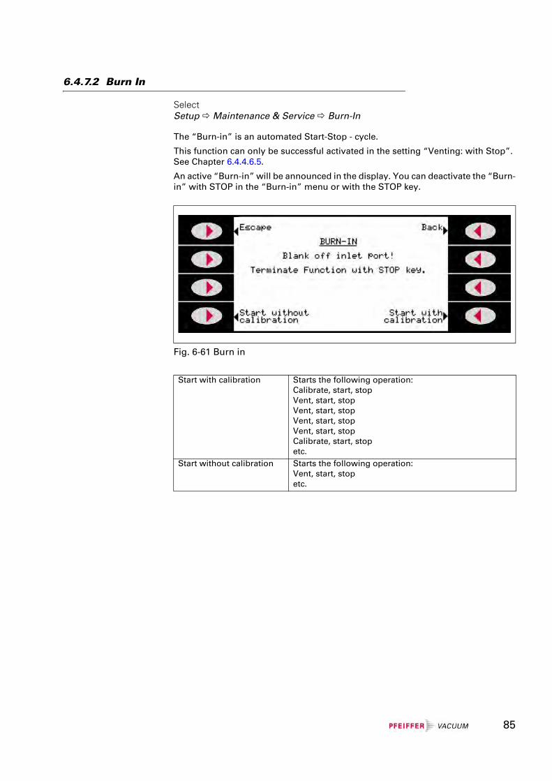
6.4.7.2 Burn In
Select Setup Maintenance & Service Burn-In
The “Burn-in” is an automated Start-Stop - cycle.
This function can only be successful activated in the setting “Venting: with Stop”. See Chapter 6.4.4.6.5.
An active “Burn-in” will be announced in the display. You can deactivate the “Burn-in” with STOP in the “Burn-in” menu or with the STOP key.
Fig. 6-61 Burn in
Start with calibration Starts the following operation:Calibrate, start, stopVent, start, stopVent, start, stopVent, start, stopVent, start, stopCalibrate, start, stopetc.
Start without calibration Starts the following operation:Vent, start, stopetc.
85
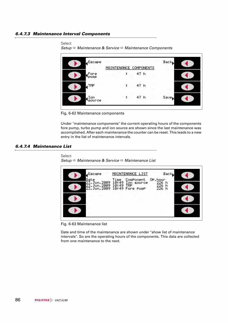
6.4.7.3 Maintenance Interval Components
Select Setup Maintenance & Service Maintenance Components
Under "maintenance components" the current operating hours of the components fore pump, turbo pump and ion source are shown since the last maintenance was accomplished. After each maintenance the counter can be reset. This leads to a new entry in the list of maintenance intervals.
6.4.7.4 Maintenance List
Select Setup Maintenance & Service Maintenance List
Date and time of the maintenance are shown under "show list of maintenance intervals". So are the operating hours of the components. This data are collected from one maintenance to the next.
Fig. 6-62 Maintenance components
Fig. 6-63 Maintenance list
86
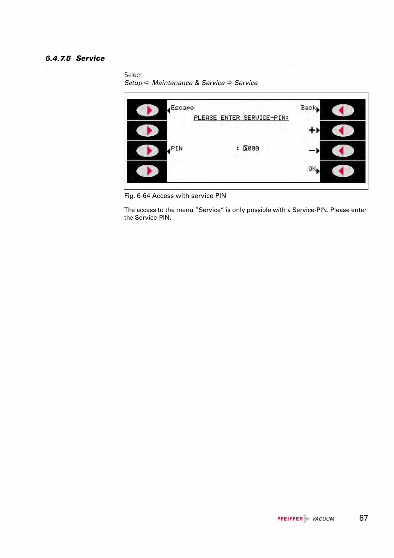
6.4.7.5 Service
Select Setup Maintenance & Service Service
The access to the menu ”Service” is only possible with a Service-PIN. Please enter the Service-PIN.
Fig. 6-64 Access with service PIN
87
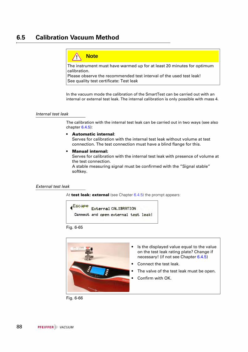
6.5 Calibration Vacuum Method
In the vacuum mode the calibration of the SmartTest can be carried out with an internal or external test leak. The internal calibration is only possible with mass 4.
Internal test leak
The calibration with the internal test leak can be carried out in two ways (see also chapter 6.4.5):
• Automatic internal:Serves for calibration with the internal test leak without volume at test connection. The test connection must have a blind flange for this.
• Manual internal:Serves for calibration with the internal test leak with presence of volume at the test connection.A stable measuring signal must be confirmed with the ”Signal stable” softkey.
External test leak
At test leak: external (see Chapter 6.4.5) the prompt appears:
NoteThe instrument must have warmed up for at least 20 minutes for optimum calibration.Please observe the recommended test interval of the used test leak!See quality test certificate: Test leak
Fig. 6-65
• Is the displayed value equal to the value on the test leak rating plate? Change if necessary! (if not see Chapter 6.4.5)
• Connect the test leak.
• The valve of the test leak must be open.
• Confirm with OK.
Fig. 6-66
88
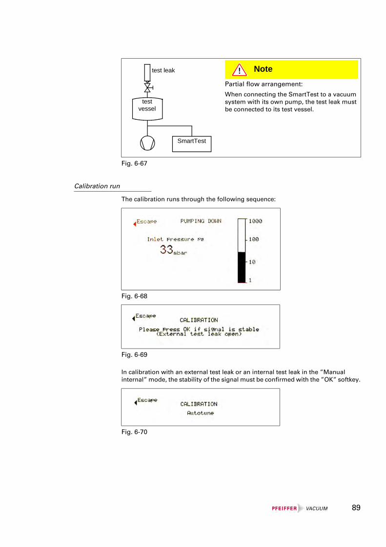
Calibration run
The calibration runs through the following sequence:
In calibration with an external test leak or an internal test leak in the ”Manual internal” mode, the stability of the signal must be confirmed with the ”OK” softkey.
NotePartial flow arrangement:
When connecting the SmartTest to a vacuum system with its own pump, the test leak must be connected to its test vessel.
Fig. 6-67
SmartTest
test leak
testvessel
Fig. 6-68
Fig. 6-69
Fig. 6-70
89
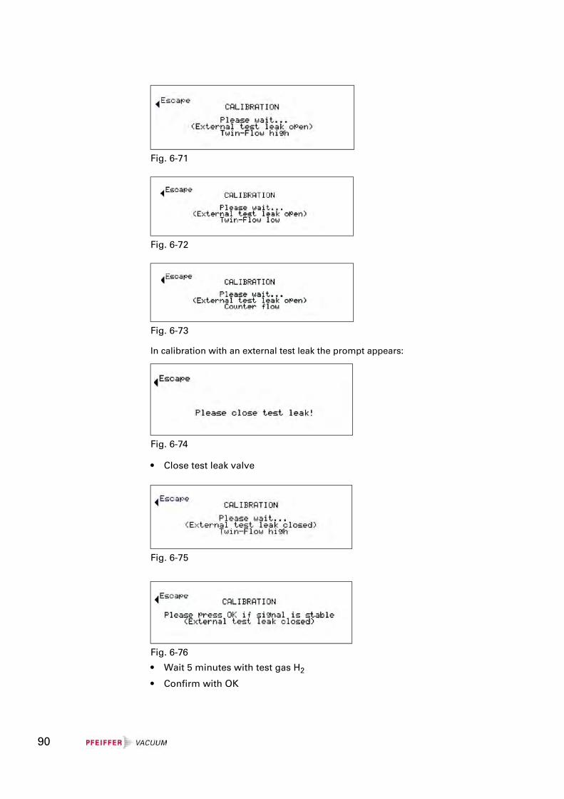
In calibration with an external test leak the prompt appears:
• Close test leak valve
• Wait 5 minutes with test gas H2
• Confirm with OK
Fig. 6-71
Fig. 6-72
Fig. 6-73
Fig. 6-74
Fig. 6-75
Fig. 6-76
90
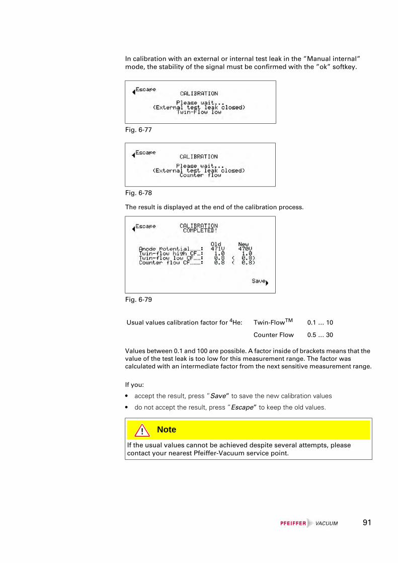
In calibration with an external or internal test leak in the ”Manual internal” mode, the stability of the signal must be confirmed with the ”ok” softkey.
The result is displayed at the end of the calibration process.
Values between 0.1 and 100 are possible. A factor inside of brackets means that the value of the test leak is too low for this measurement range. The factor was calculated with an intermediate factor from the next sensitive measurement range.
If you:
• accept the result, press ”Save” to save the new calibration values
• do not accept the result, press ”Escape” to keep the old values.
Fig. 6-77
Fig. 6-78
Fig. 6-79
Usual values calibration factor for 4He: Twin-FlowTM 0.1 … 10
Counter Flow 0.5 … 30
NoteIf the usual values cannot be achieved despite several attempts, please contact your nearest Pfeiffer-Vacuum service point.
91
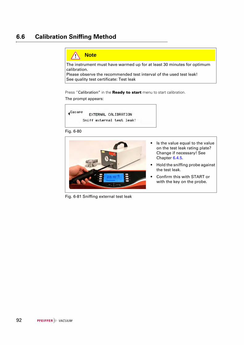
6.6 Calibration Sniffing Method
Press ”Calibration” in the Ready to start menu to start calibration.
The prompt appears:
NoteThe instrument must have warmed up for at least 30 minutes for optimum calibration.Please observe the recommended test interval of the used test leak!See quality test certificate: Test leak
Fig. 6-80
• Is the value equal to the value on the test leak rating plate? Change if necessary! See Chapter 6.4.5.
• Hold the sniffing probe against the test leak.
• Confirm this with START or with the key on the probe.
Fig. 6-81 Sniffing external test leak
92
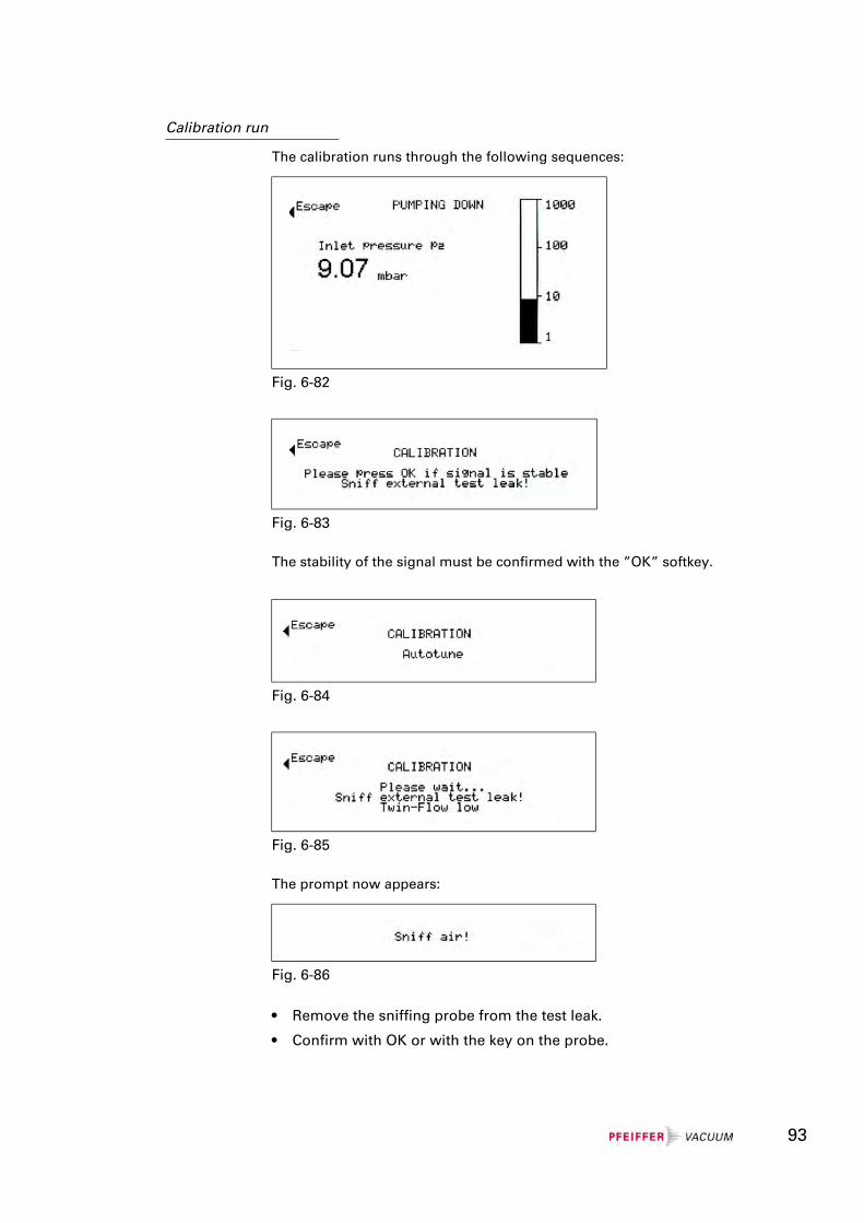
Calibration run
The calibration runs through the following sequences:
The stability of the signal must be confirmed with the ”OK” softkey.
The prompt now appears:
• Remove the sniffing probe from the test leak.
• Confirm with OK or with the key on the probe.
Fig. 6-82
Fig. 6-83
Fig. 6-84
Fig. 6-85
Fig. 6-86
93
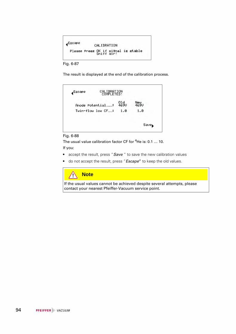
The result is displayed at the end of the calibration process.
The usual value calibration factor CF for 4He is: 0.1 … 10.
If you:
• accept the result, press ”Save ” to save the new calibration values
• do not accept the result, press ”Escape” to keep the old values.
Fig. 6-87
Fig. 6-88
NoteIf the usual values cannot be achieved despite several attempts, please contact your nearest Pfeiffer-Vacuum service point.
94
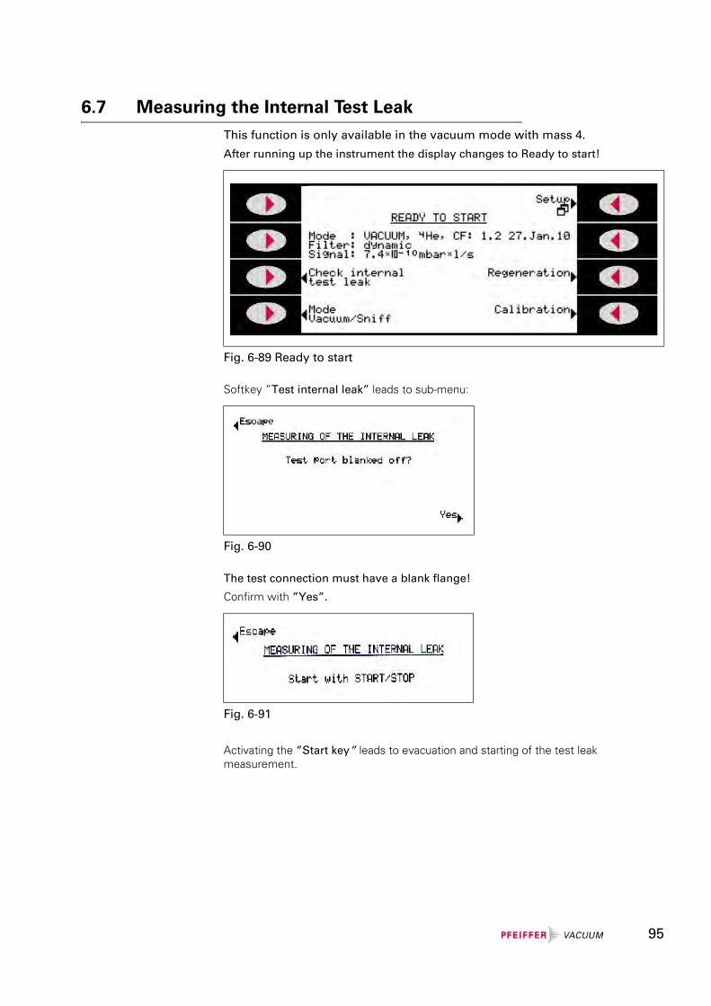
6.7 Measuring the Internal Test LeakThis function is only available in the vacuum mode with mass 4.
After running up the instrument the display changes to Ready to start!
Softkey ”Test internal leak” leads to sub-menu:
The test connection must have a blank flange!
Confirm with ”Yes”.
Activating the ”Start key” leads to evacuation and starting of the test leak measurement.
Fig. 6-89 Ready to start
Fig. 6-90
Fig. 6-91
95
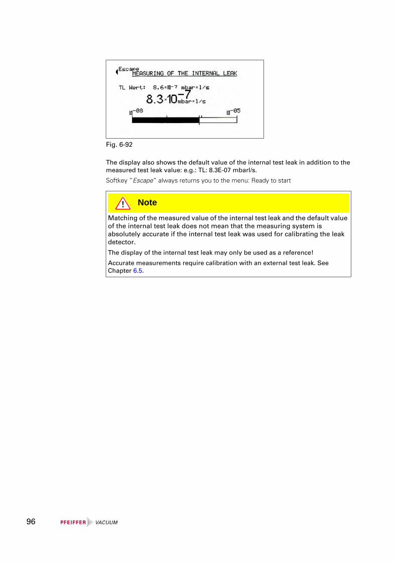
The display also shows the default value of the internal test leak in addition to the measured test leak value: e.g.: TL: 8.3E-07 mbarl/s.
Softkey ”Escape” always returns you to the menu: Ready to start
Fig. 6-92
NoteMatching of the measured value of the internal test leak and the default value of the internal test leak does not mean that the measuring system is absolutely accurate if the internal test leak was used for calibrating the leak detector.
The display of the internal test leak may only be used as a reference!
Accurate measurements require calibration with an external test leak. See Chapter 6.5.
96
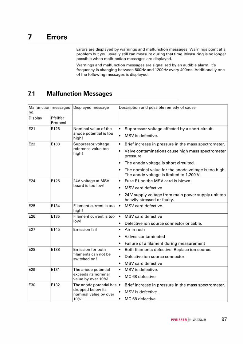
7 Errors
Errors are displayed by warnings and malfunction messages. Warnings point at a problem but you usually still can measure during that time. Measuring is no longer possible when malfunction messages are displayed.
Warnings and malfunction messages are signalized by an audible alarm. It’s frequency is changing between 500Hz and 1200Hz every 400ms. Additionally one of the following messages is displayed:
7.1 Malfunction Messages
Malfunction messages no.
Displayed message Description and possible remedy of cause
Display Pfeiffer Protocol
E21 E128 Nominal value of the anode potential is too high!
• Suppressor voltage affected by a short-circuit.
• MSV is defective.
E22 E133 Suppressor voltage reference value too high!
• Brief increase in pressure in the mass spectrometer.
• Valve contaminations cause high mass spectrometer pressure.
• The anode voltage is short circuited.
• The nominal value for the anode voltage is too high. The anode voltage is limited to 1,200 V.
E24 E125 24V voltage at MSV board is too low!
• Fuse F1 on the MSV card is blown.
• MSV card defective
• 24 V supply voltage from main power supply unit too heavily stressed or faulty.
E25 E134 Filament current is too high!
• MSV card defective.
E26 E135 Filament current is too low!
• MSV card defective
• Defective ion source connector or cable.E27 E145 Emission fail • Air in rush
• Valves contaminated
• Failure of a filament during measurementE28 E138 Emission for both
filaments can not be switched on!
• Both filaments defective. Replace ion source.
• Defective ion source connector.
• MSV card defectiveE29 E131 The anode potential
exceeds its nominal value by over 10%!
• MSV is defective.
• MC 68 defective
E30 E132 The anode potential has dropped below its nominal value by over 10%!
• Brief increase in pressure in the mass spectrometer.
• MSV is defective.
• MC 68 defective
97
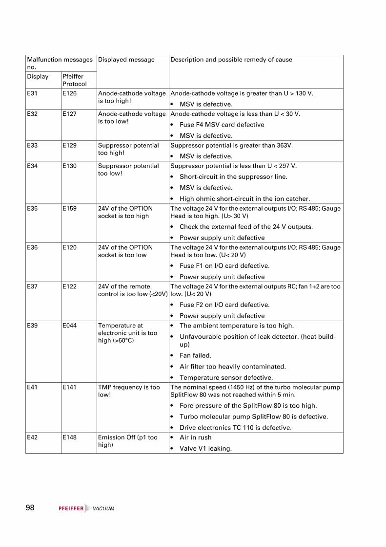
E31 E126 Anode-cathode voltage is too high!
Anode-cathode voltage is greater than U > 130 V.
• MSV is defective.E32 E127 Anode-cathode voltage
is too low!Anode-cathode voltage is less than U < 30 V.
• Fuse F4 MSV card defective
• MSV is defective.E33 E129 Suppressor potential
too high!Suppressor potential is greater than 363V.
• MSV is defective.E34 E130 Suppressor potential
too low!Suppressor potential is less than U < 297 V.
• Short-circuit in the suppressor line.
• MSV is defective.
• High ohmic short-circuit in the ion catcher. E35 E159 24V of the OPTION
socket is too highThe voltage 24 V for the external outputs I/O; RS 485; Gauge Head is too high. (U> 30 V)
• Check the external feed of the 24 V outputs.
• Power supply unit defectiveE36 E120 24V of the OPTION
socket is too lowThe voltage 24 V for the external outputs I/O; RS 485; Gauge Head is too low. (U< 20 V)
• Fuse F1 on I/O card defective.
• Power supply unit defectiveE37 E122 24V of the remote
control is too low (<20V)The voltage 24 V for the external outputs RC; fan 1+2 are too low. (U< 20 V)
• Fuse F2 on I/O card defective.
• Power supply unit defectiveE39 E044 Temperature at
electronic unit is too high (>60°C)
• The ambient temperature is too high.
• Unfavourable position of leak detector. (heat build-up)
• Fan failed.
• Air filter too heavily contaminated.
• Temperature sensor defective.E41 E141 TMP frequency is too
low!The nominal speed (1450 Hz) of the turbo molecular pump SplitFlow 80 was not reached within 5 min.
• Fore pressure of the SplitFlow 80 is too high.
• Turbo molecular pump SplitFlow 80 is defective.
• Drive electronics TC 110 is defective.E42 E148 Emission Off (p1 too
high)• Air in rush
• Valve V1 leaking.
Malfunction messages no.
Displayed message Description and possible remedy of cause
Display Pfeiffer Protocol
98
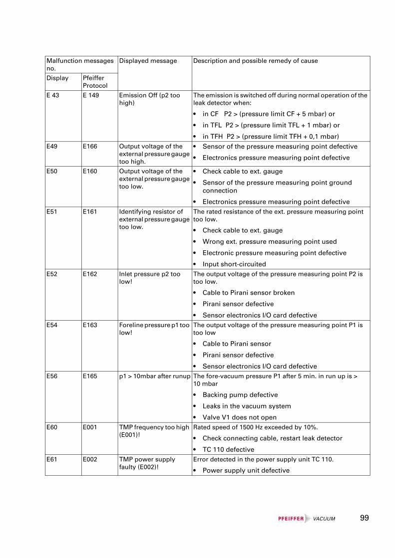
E 43 E 149 Emission Off (p2 too high)
The emission is switched off during normal operation of the leak detector when:
• in CF P2 > (pressure limit CF + 5 mbar) or
• in TFL P2 > (pressure limit TFL + 1 mbar) or
• in TFH P2 > (pressure limit TFH + 0,1 mbar) E49 E166 Output voltage of the
external pressure gauge too high.
• Sensor of the pressure measuring point defective
• Electronics pressure measuring point defective
E50 E160 Output voltage of the external pressure gauge too low.
• Check cable to ext. gauge
• Sensor of the pressure measuring point ground connection
• Electronics pressure measuring point defectiveE51 E161 Identifying resistor of
external pressure gauge too low.
The rated resistance of the ext. pressure measuring point too low.
• Check cable to ext. gauge
• Wrong ext. pressure measuring point used
• Electronic pressure measuring point defective
• Input short-circuitedE52 E162 Inlet pressure p2 too
low!The output voltage of the pressure measuring point P2 is too low.
• Cable to Pirani sensor broken
• Pirani sensor defective
• Sensor electronics I/O card defectiveE54 E163 Foreline pressure p1 too
low!The output voltage of the pressure measuring point P1 is too low
• Cable to Pirani sensor
• Pirani sensor defective
• Sensor electronics I/O card defectiveE56 E165 p1 > 10mbar after runup The fore-vacuum pressure P1 after 5 min. in run up is >
10 mbar
• Backing pump defective
• Leaks in the vacuum system
• Valve V1 does not openE60 E001 TMP frequency too high
(E001)!Rated speed of 1500 Hz exceeded by 10%.
• Check connecting cable, restart leak detector
• TC 110 defectiveE61 E002 TMP power supply
faulty (E002)!Error detected in the power supply unit TC 110.
• Power supply unit defective
Malfunction messages no.
Displayed message Description and possible remedy of cause
Display Pfeiffer Protocol
99
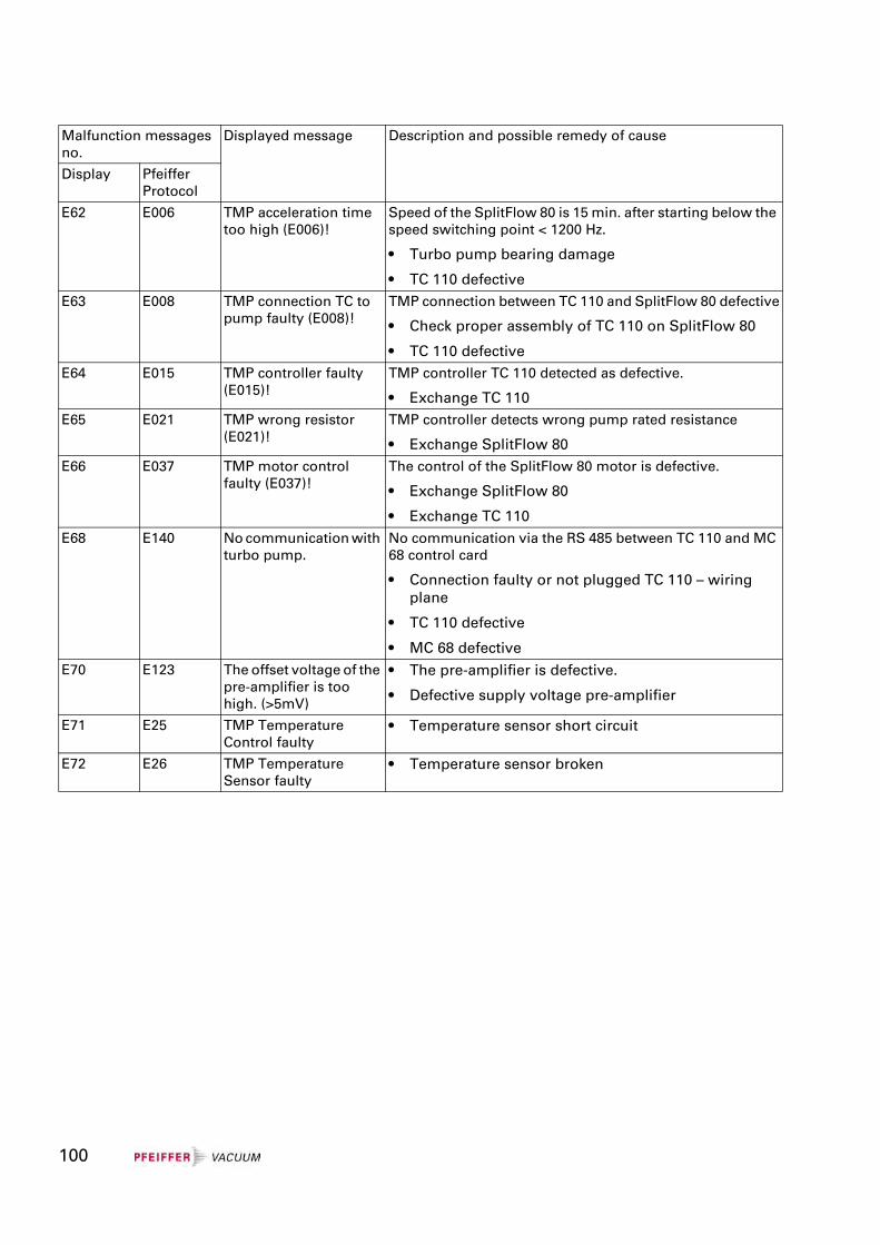
E62 E006 TMP acceleration time too high (E006)!
Speed of the SplitFlow 80 is 15 min. after starting below the speed switching point < 1200 Hz.
• Turbo pump bearing damage
• TC 110 defectiveE63 E008 TMP connection TC to
pump faulty (E008)!TMP connection between TC 110 and SplitFlow 80 defective
• Check proper assembly of TC 110 on SplitFlow 80
• TC 110 defective E64 E015 TMP controller faulty
(E015)!TMP controller TC 110 detected as defective.
• Exchange TC 110E65 E021 TMP wrong resistor
(E021)!TMP controller detects wrong pump rated resistance
• Exchange SplitFlow 80E66 E037 TMP motor control
faulty (E037)!The control of the SplitFlow 80 motor is defective.
• Exchange SplitFlow 80
• Exchange TC 110E68 E140 No communication with
turbo pump.No communication via the RS 485 between TC 110 and MC 68 control card
• Connection faulty or not plugged TC 110 – wiring plane
• TC 110 defective
• MC 68 defectiveE70 E123 The offset voltage of the
pre-amplifier is too high. (>5mV)
• The pre-amplifier is defective.
• Defective supply voltage pre-amplifier
E71 E25 TMP Temperature Control faulty
• Temperature sensor short circuit
E72 E26 TMP Temperature Sensor faulty
• Temperature sensor broken
Malfunction messages no.
Displayed message Description and possible remedy of cause
Display Pfeiffer Protocol
100
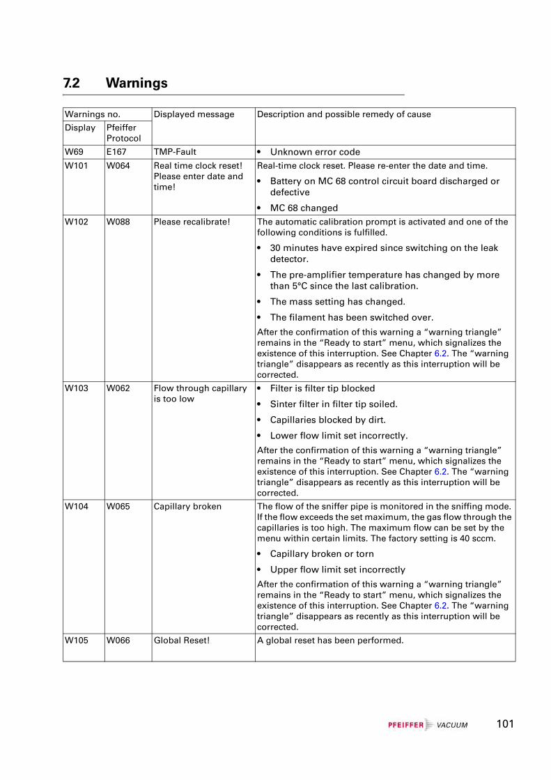
7.2 Warnings
Warnings no. Displayed message Description and possible remedy of cause
Display Pfeiffer Protocol
W69 E167 TMP-Fault • Unknown error codeW101 W064 Real time clock reset!
Please enter date and time!
Real-time clock reset. Please re-enter the date and time.
• Battery on MC 68 control circuit board discharged or defective
• MC 68 changedW102 W088 Please recalibrate! The automatic calibration prompt is activated and one of the
following conditions is fulfilled.
• 30 minutes have expired since switching on the leak detector.
• The pre-amplifier temperature has changed by more than 5°C since the last calibration.
• The mass setting has changed.
• The filament has been switched over.
After the confirmation of this warning a “warning triangle” remains in the “Ready to start” menu, which signalizes the existence of this interruption. See Chapter 6.2. The “warning triangle” disappears as recently as this interruption will be corrected.
W103 W062 Flow through capillary is too low
• Filter is filter tip blocked
• Sinter filter in filter tip soiled.
• Capillaries blocked by dirt.
• Lower flow limit set incorrectly.
After the confirmation of this warning a “warning triangle” remains in the “Ready to start” menu, which signalizes the existence of this interruption. See Chapter 6.2. The “warning triangle” disappears as recently as this interruption will be corrected.
W104 W065 Capillary broken The flow of the sniffer pipe is monitored in the sniffing mode. If the flow exceeds the set maximum, the gas flow through the capillaries is too high. The maximum flow can be set by the menu within certain limits. The factory setting is 40 sccm.
• Capillary broken or torn
• Upper flow limit set incorrectly
After the confirmation of this warning a “warning triangle” remains in the “Ready to start” menu, which signalizes the existence of this interruption. See Chapter 6.2. The “warning triangle” disappears as recently as this interruption will be corrected.
W105 W066 Global Reset! A global reset has been performed.
101
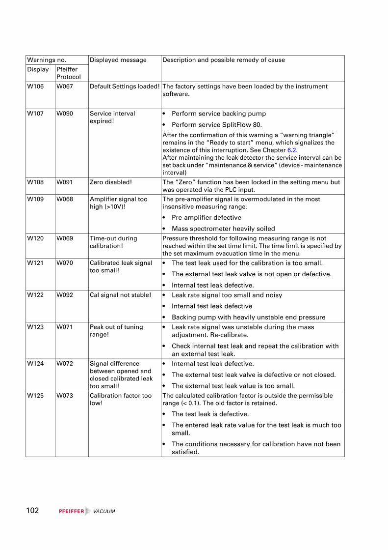
W106 W067 Default Settings loaded! The factory settings have been loaded by the instrument software.
W107 W090 Service interval expired!
• Perform service backing pump
• Perform service SplitFlow 80.
After the confirmation of this warning a “warning triangle” remains in the “Ready to start” menu, which signalizes the existence of this interruption. See Chapter 6.2.After maintaining the leak detector the service interval can be set back under ”maintenance & service“ (device - maintenance interval)
W108 W091 Zero disabled! The ”Zero” function has been locked in the setting menu but was operated via the PLC input.
W109 W068 Amplifier signal too high (>10V)!
The pre-amplifier signal is overmodulated in the most insensitive measuring range.
• Pre-amplifier defective
• Mass spectrometer heavily soiledW120 W069 Time-out during
calibration!Pressure threshold for following measuring range is not reached within the set time limit. The time limit is specified by the set maximum evacuation time in the menu.
W121 W070 Calibrated leak signal too small!
• The test leak used for the calibration is too small.
• The external test leak valve is not open or defective.
• Internal test leak defective.W122 W092 Cal signal not stable! • Leak rate signal too small and noisy
• Internal test leak defective
• Backing pump with heavily unstable end pressureW123 W071 Peak out of tuning
range!• Leak rate signal was unstable during the mass
adjustment. Re-calibrate.
• Check internal test leak and repeat the calibration with an external test leak.
W124 W072 Signal difference between opened and closed calibrated leak too small!
• Internal test leak defective.
• The external test leak valve is defective or not closed.
• The external test leak value is too small.W125 W073 Calibration factor too
low!The calculated calibration factor is outside the permissible range (< 0.1). The old factor is retained.
• The test leak is defective.
• The entered leak rate value for the test leak is much too small.
• The conditions necessary for calibration have not been satisfied.
Warnings no. Displayed message Description and possible remedy of cause
Display Pfeiffer Protocol
102
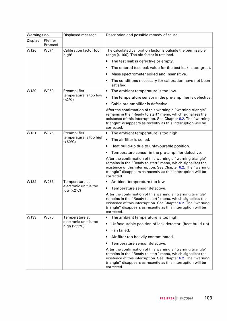
W126 W074 Calibration factor too high!
The calculated calibration factor is outside the permissible range (> 100). The old factor is retained.
• The test leak is defective or empty.
• The entered test leak value for the test leak is too great.
• Mass spectrometer soiled and insensitive.
• The conditions necessary for calibration have not been satisfied.
W130 W060 Preamplifier temperature is too low (<2°C)
• The ambient temperature is too low.
• The temperature sensor in the pre-amplifier is defective.
• Cable pre-amplifier is defective.
After the confirmation of this warning a “warning triangle” remains in the “Ready to start” menu, which signalizes the existence of this interruption. See Chapter 6.2. The “warning triangle” disappears as recently as this interruption will be corrected.
W131 W075 Preamplifier temperature is too high (>60°C)
• The ambient temperature is too high.
• The air filter is soiled.
• Heat build-up due to unfavourable position.
• Temperature sensor in the pre-amplifier defective.
After the confirmation of this warning a “warning triangle” remains in the “Ready to start” menu, which signalizes the existence of this interruption. See Chapter 6.2. The “warning triangle” disappears as recently as this interruption will be corrected.
W132 W063 Temperature at electronic unit is too low (<2°C)
• Ambient temperature too low
• Temperature sensor defective.
After the confirmation of this warning a “warning triangle” remains in the “Ready to start” menu, which signalizes the existence of this interruption. See Chapter 6.2. The “warning triangle” disappears as recently as this interruption will be corrected.
W133 W076 Temperature at electronic unit is too high (>55°C)
• The ambient temperature is too high.
• Unfavourable position of leak detector. (heat build-up)
• Fan failed.
• Air filter too heavily contaminated.
• Temperature sensor defective.
After the confirmation of this warning a “warning triangle” remains in the “Ready to start” menu, which signalizes the existence of this interruption. See Chapter 6.2. The “warning triangle” disappears as recently as this interruption will be corrected.
Warnings no. Displayed message Description and possible remedy of cause
Display Pfeiffer Protocol
103
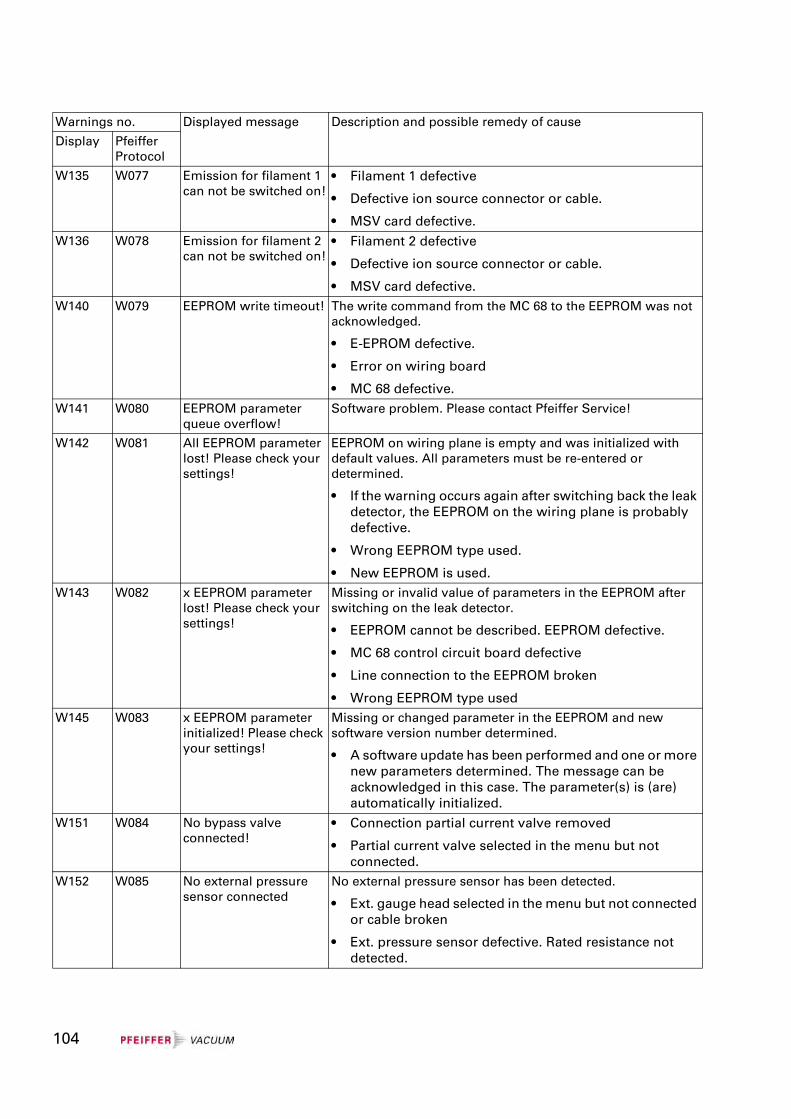
W135 W077 Emission for filament 1 can not be switched on!
• Filament 1 defective
• Defective ion source connector or cable.
• MSV card defective.W136 W078 Emission for filament 2
can not be switched on!• Filament 2 defective
• Defective ion source connector or cable.
• MSV card defective.W140 W079 EEPROM write timeout! The write command from the MC 68 to the EEPROM was not
acknowledged.
• E-EPROM defective.
• Error on wiring board
• MC 68 defective.W141 W080 EEPROM parameter
queue overflow!Software problem. Please contact Pfeiffer Service!
W142 W081 All EEPROM parameter lost! Please check your settings!
EEPROM on wiring plane is empty and was initialized with default values. All parameters must be re-entered or determined.
• If the warning occurs again after switching back the leak detector, the EEPROM on the wiring plane is probably defective.
• Wrong EEPROM type used.
• New EEPROM is used.W143 W082 x EEPROM parameter
lost! Please check your settings!
Missing or invalid value of parameters in the EEPROM after switching on the leak detector.
• EEPROM cannot be described. EEPROM defective.
• MC 68 control circuit board defective
• Line connection to the EEPROM broken
• Wrong EEPROM type usedW145 W083 x EEPROM parameter
initialized! Please check your settings!
Missing or changed parameter in the EEPROM and new software version number determined.
• A software update has been performed and one or more new parameters determined. The message can be acknowledged in this case. The parameter(s) is (are) automatically initialized.
W151 W084 No bypass valve connected!
• Connection partial current valve removed
• Partial current valve selected in the menu but not connected.
W152 W085 No external pressure sensor connected
No external pressure sensor has been detected.
• Ext. gauge head selected in the menu but not connected or cable broken
• Ext. pressure sensor defective. Rated resistance not detected.
Warnings no. Displayed message Description and possible remedy of cause
Display Pfeiffer Protocol
104
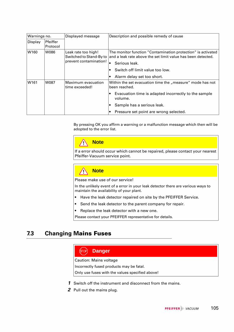
By pressing OK you affirm a warning or a malfunction message which then will be adopted to the error list.
7.3 Changing Mains Fuses
1 Switch off the instrument and disconnect from the mains.
2 Pull out the mains plug.
W160 W086 Leak rate too high! Switched to Stand-By to prevent contamination!
The monitor function ”Contamination protection” is activated and a leak rate above the set limit value has been detected.
• Serious leak.
• Switch off limit value too low.
• Alarm delay set too short.W161 W087 Maximum evacuation
time exceeded!Within the set evacuation time the „measure“ mode has not been reached.
• Evacuation time is adapted incorrectly to the sample volume.
• Sample has a serious leak.
• Pressure set point are wrong selected.
Warnings no. Displayed message Description and possible remedy of cause
Display Pfeiffer Protocol
NoteIf a error should occur which cannot be repaired, please contact your nearest Pfeiffer-Vacuum service point.
NotePlease make use of our service!
In the unlikely event of a error in your leak detector there are various ways to maintain the availability of your plant.
• Have the leak detector repaired on site by the PFEIFFER Service.
• Send the leak detector to the parent company for repair.
• Replace the leak detector with a new one.
Please contact your PFEIFFER representative for details.
STOP Danger
Caution: Mains voltage
Incorrectly fused products may be fatal.
Only use fuses with the values specified above!
105
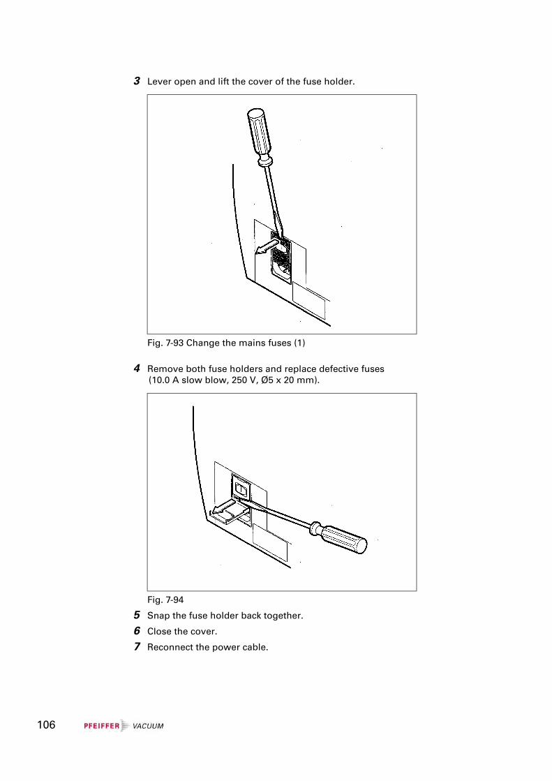
3 Lever open and lift the cover of the fuse holder.
4 Remove both fuse holders and replace defective fuses(10.0 A slow blow, 250 V, Ø5 x 20 mm).
5 Snap the fuse holder back together.
6 Close the cover.
7 Reconnect the power cable.
Fig. 7-93 Change the mains fuses (1)
Fig. 7-94
106
107
8 Disposal
Division of the components
After dismantling the product, the components must be divided into the following categories for disposal:
Contaminated components
Contaminated components (radioactive, toxic, caustic, microbiological, etc.) must be decontaminated according to national regulations, separated and disposed of according to their type of material.
Uncontaminated components
These components must be separated according to their type of material and recycled.
Operating fluids
Operating fluids of the backing pump and high vacuum pumps must be disposed of according to the local regulations.
STOP Danger
Caution: Contaminated parts
Contaminated parts can cause damage to health and the environment.
Find out about possible contamination before starting work. Observe the pertinent regulations and safety precautions when handling contaminated parts.
WarningCaution: Materials which are harmful to the environment
Products or parts (mechanical and electrical components, operating fluids etc.) can be harmful to the environment.
Dispose of such harmful materials according to local regulations.
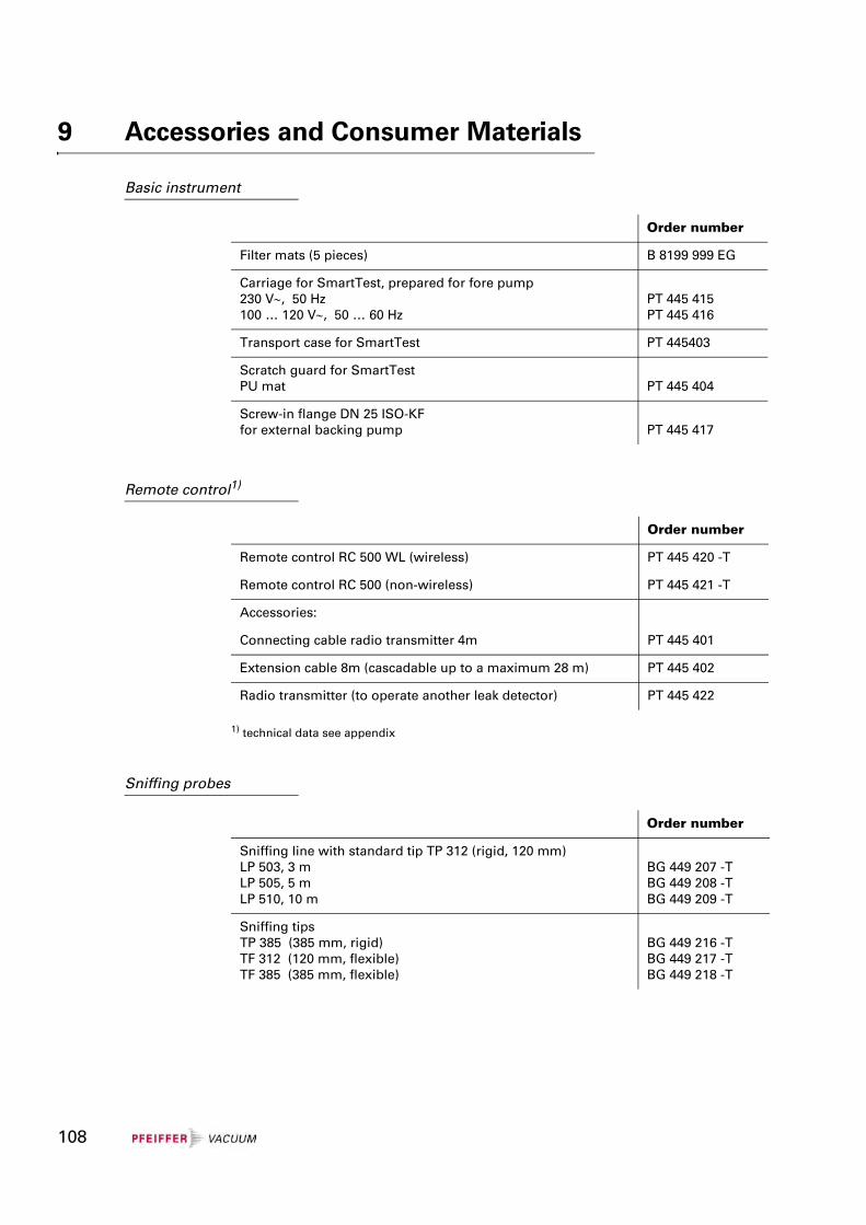
9 Accessories and Consumer Materials
Basic instrument
Remote control1)
1) technical data see appendix
Sniffing probes
Order number
Filter mats (5 pieces) B 8199 999 EG
Carriage for SmartTest, prepared for fore pump230 V∼, 50 Hz100 … 120 V∼, 50 … 60 Hz
PT 445 415PT 445 416
Transport case for SmartTest PT 445403
Scratch guard for SmartTestPU mat PT 445 404
Screw-in flange DN 25 ISO-KFfor external backing pump PT 445 417
Order number
Remote control RC 500 WL (wireless) PT 445 420 -T
Remote control RC 500 (non-wireless) PT 445 421 -T
Accessories:
Connecting cable radio transmitter 4m PT 445 401
Extension cable 8m (cascadable up to a maximum 28 m) PT 445 402
Radio transmitter (to operate another leak detector) PT 445 422
Order number
Sniffing line with standard tip TP 312 (rigid, 120 mm)LP 503, 3 mLP 505, 5 mLP 510, 10 m
BG 449 207 -TBG 449 208 -TBG 449 209 -T
Sniffing tipsTP 385 (385 mm, rigid)TF 312 (120 mm, flexible)TF 385 (385 mm, flexible)
BG 449 216 -TBG 449 217 -TBG 449 218 -T
108
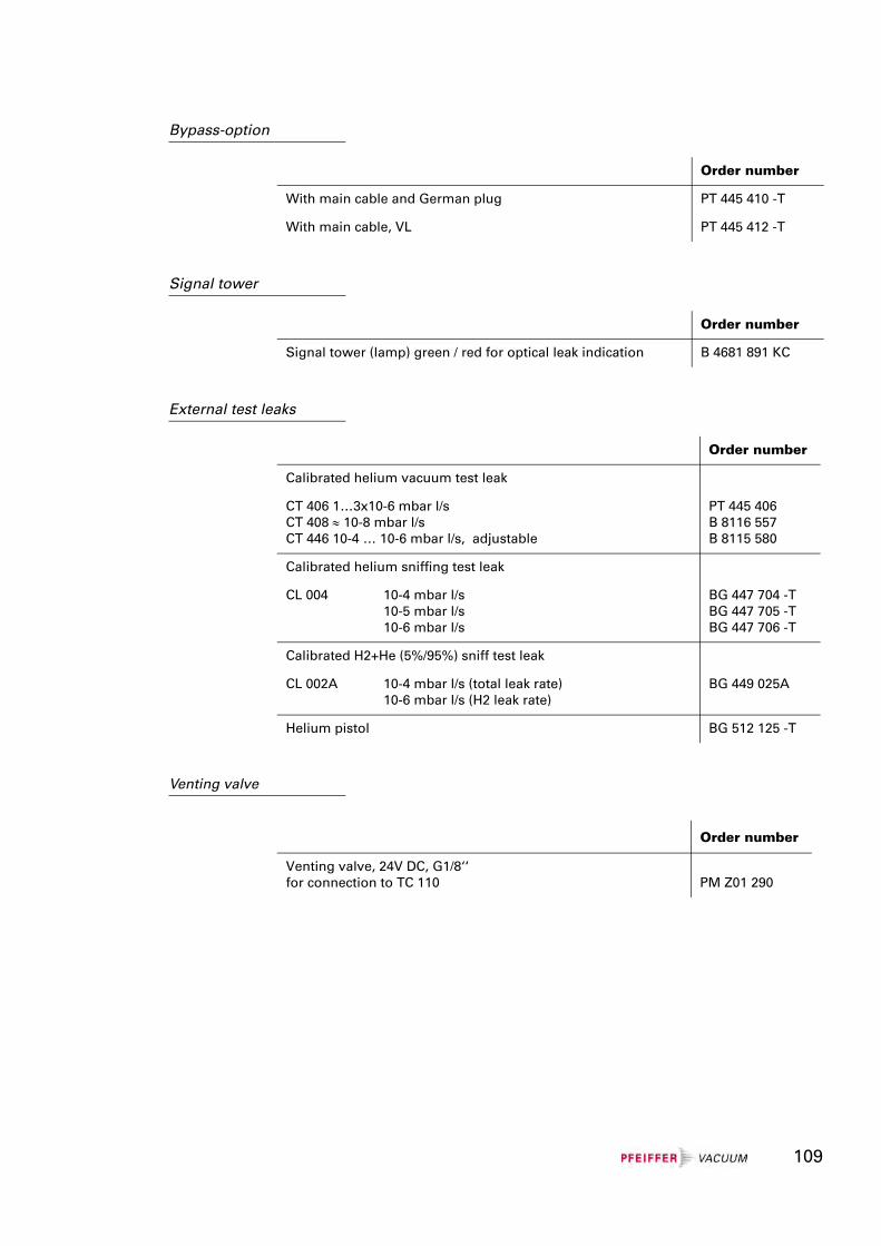
Bypass-option
Signal tower
External test leaks
Venting valve
Order number
With main cable and German plug PT 445 410 -T
With main cable, VL PT 445 412 -T
Order number
Signal tower (lamp) green / red for optical leak indication B 4681 891 KC
Order number
Calibrated helium vacuum test leak
CT 406 1…3x10⁻⁶ mbar l/sCT 408 ≈ 10-8 mbar l/sCT 446 10-4 … 10-6 mbar l/s, adjustable
PT 445 406B 8116 557B 8115 580
Calibrated helium sniffing test leak
CL 004 10-4 mbar l/s10-5 mbar l/s10-6 mbar l/s
BG 447 704 -TBG 447 705 -TBG 447 706 -T
Calibrated H2+He (5%/95%) sniff test leak
CL 002A 10-4 mbar l/s (total leak rate)10-6 mbar l/s (H2 leak rate)
BG 449 025A
Helium pistol BG 512 125 -T
Order number
Venting valve, 24V DC, G1/8‘‘ for connection to TC 110 PM Z01 290
109
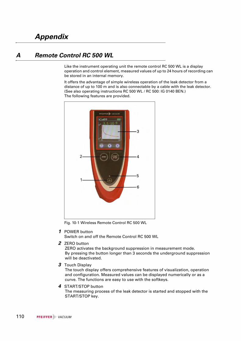
Appendix
A Remote Control RC 500 WL
Like the instrument operating unit the remote control RC 500 WL is a display operation and control element, measured values of up to 24 hours of recording can be stored in an internal memory.
It offers the advantage of simple wireless operation of the leak detector from a distance of up to 100 m and is also connectable by a cable with the leak detector. (See also operating instructions RC 500 WL / RC 500: IG 0140 BEN.) The following features are provided.
1 POWER buttonSwitch on and off the Remote Control RC 500 WL
2 ZERO buttonZERO activates the background suppression in measurement mode. By pressing the button longer than 3 seconds the underground suppression will be deactivated.
3 Touch DisplayThe touch display offers comprehensive features of visualization, operation and configuration. Measured values can be displayed numerically or as a curve. The functions are easy to use with the softkeys.
4 START/STOP buttonThe measuring process of the leak detector is started and stopped with the START/STOP key.
Fig. 10-1 Wireless Remote Control RC 500 WL
110
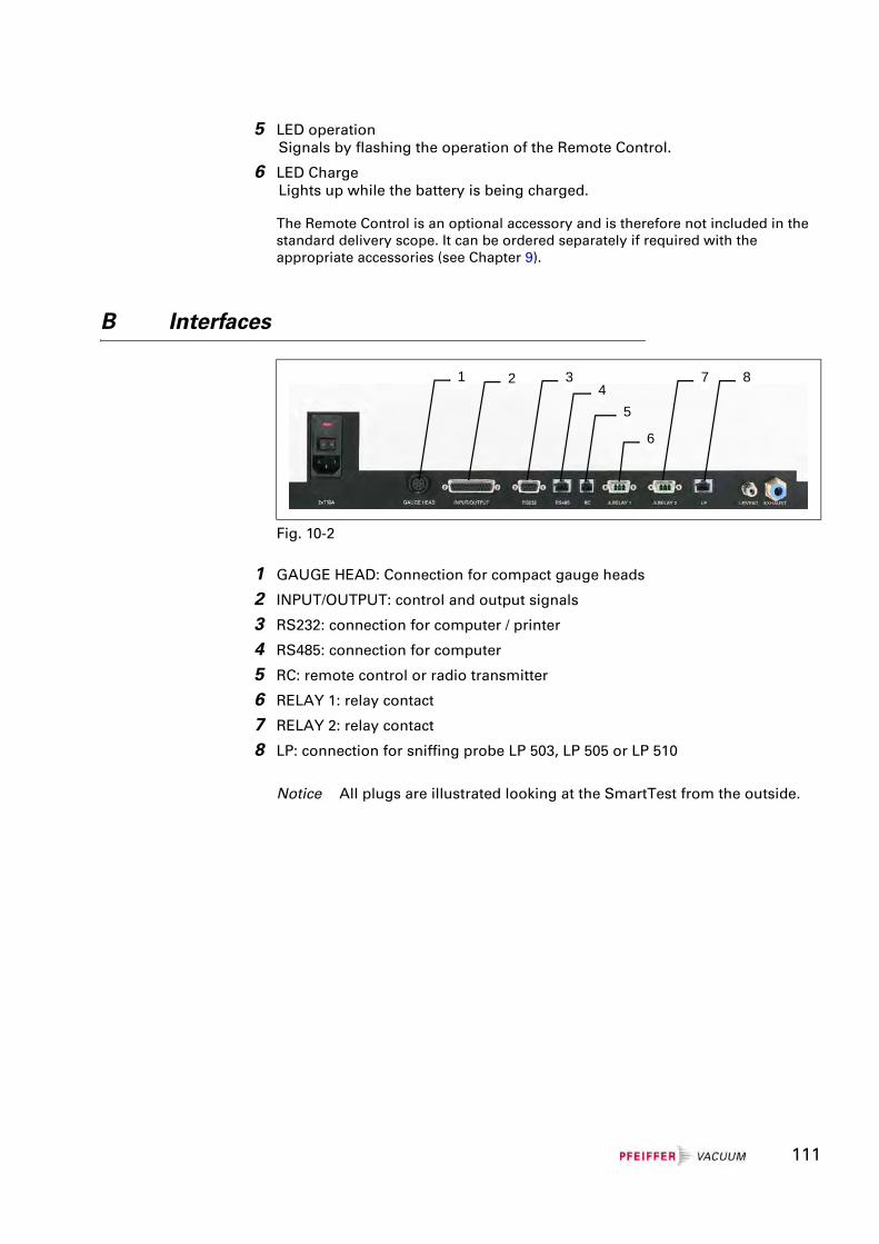
5 LED operationSignals by flashing the operation of the Remote Control.
6 LED ChargeLights up while the battery is being charged.
The Remote Control is an optional accessory and is therefore not included in the standard delivery scope. It can be ordered separately if required with the appropriate accessories (see Chapter 9).
B Interfaces
1 GAUGE HEAD: Connection for compact gauge heads
2 INPUT/OUTPUT: control and output signals
3 RS232: connection for computer / printer
4 RS485: connection for computer
5 RC: remote control or radio transmitter
6 RELAY 1: relay contact
7 RELAY 2: relay contact
8 LP: connection for sniffing probe LP 503, LP 505 or LP 510
Notice All plugs are illustrated looking at the SmartTest from the outside.
Fig. 10-2
1 2 34
5
6
7 8
111
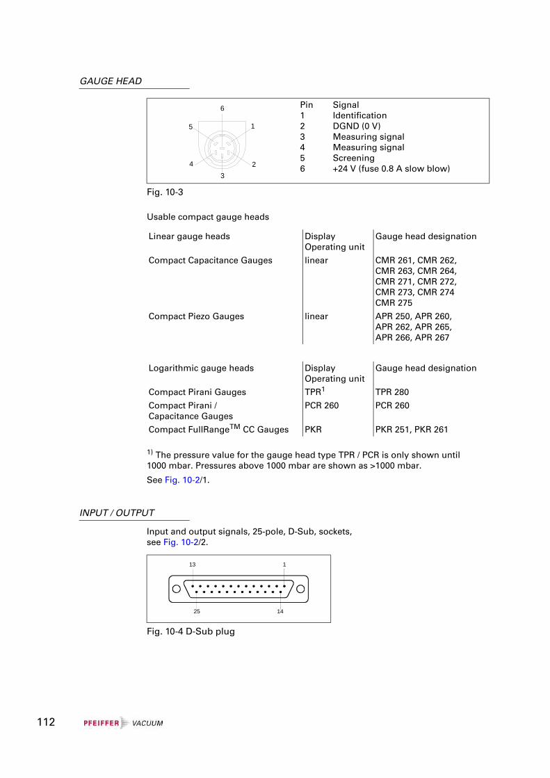
GAUGE HEAD
Usable compact gauge heads
1) The pressure value for the gauge head type TPR / PCR is only shown until 1000 mbar. Pressures above 1000 mbar are shown as >1000 mbar.
See Fig. 10-2/1.
INPUT / OUTPUT
Input and output signals, 25-pole, D-Sub, sockets, see Fig. 10-2/2.
Pin123456
SignalIdentificationDGND (0 V)Measuring signalMeasuring signalScreening+24 V (fuse 0.8 A slow blow)
Fig. 10-3
Linear gauge heads DisplayOperating unit
Gauge head designation
Compact Capacitance Gauges linear CMR 261, CMR 262, CMR 263, CMR 264, CMR 271, CMR 272, CMR 273, CMR 274 CMR 275
Compact Piezo Gauges linear APR 250, APR 260, APR 262, APR 265, APR 266, APR 267
Logarithmic gauge heads DisplayOperating unit
Gauge head designation
Compact Pirani Gauges TPR1 TPR 280
Compact Pirani / Capacitance Gauges
PCR 260 PCR 260
Compact FullRangeTM CC Gauges PKR PKR 251, PKR 261
4
5 1
23
6
Fig. 10-4 D-Sub plug
1
14
13
25
112
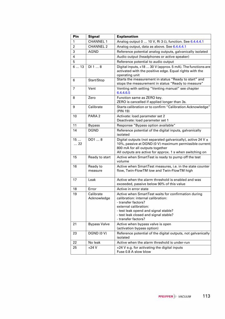
Pin Signal Explanation1 CHANNEL 1 Analog output 0 … 10 V, Ri 3 Ω, function. See 6.4.4.4.12 CHANNEL 2 Analog output, data as above. See 6.4.4.4.13 AGND Reference potential analog outputs, galvanically isolated4 Audio output (headphones or active speaker)5 Reference potential to audio output6 … 13 DI 1 … 8 Digital inputs, +18 … 30 V (approx. 5 mA). The functions are
activated with the positive edge. Equal rights with the operating unit
6 Start/Stop Starts the measurement in status “Ready to start” and stops the measurement in status “Ready to measure”
7 Vent Venting with setting “Venting manual” see chapter 6.4.4.6.5
8 Zero Function same as ZERO key.ZERO is cancelled if applied longer than 3s.
9 Calibrate Starts calibration or to confirm “Calibration Acknowledge” (PIN 19)
10 PARA 2 Activate: load parameter set 2Deactivate: load parameter set 1
11 Bypass Response ”Bypass option available”14 DGND Reference potential of the digital inputs, galvanically
isolated15 … … 22
DO1 … 8 Digital outputs (not separated galvanically), active 24 V ± 10%, passive at DGND (0 V) maximum permissible current:800 mA for all outputs togetherAll outputs are active for approx. 1 s when switching on
15 Ready to start Active when SmartTest is ready to pump off the test volume
16 Ready to measure
Active when SmartTest measures, i.e. in the state counter flow, Twin-FlowTM low and Twin-FlowTM high
17 Leak Active when the alarm threshold is enabled and was exceeded, passive below 90% of this value
18 Error Active in error state19 Calibrate
AcknowledgeActive when SmartTest waits for confirmation during calibration: internal calibration:- transfer factors?external calibration:- test leak opend and signal stable?- test leak closed and signal stable?- transfer factors?
21 Bypass Valve Active when bypass valve is open(activation bypass option)
23 DGND (0 V) Reference potential of the digital outputs, not galvanically isolated
22 No leak Active when the alarm threshold is under-run25 +24 V +24 V e.g. for activating the digital inputs
Fuse 0.8 A slow blow
113
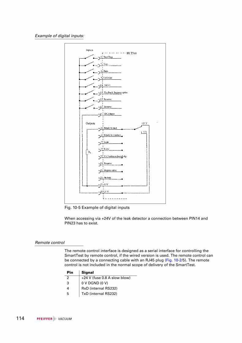
Example of digital inputs:
When accessing via +24V of the leak detector a connection between PIN14 and PIN23 has to exist.
Remote control
The remote control interface is designed as a serial interface for controlling the SmartTest by remote control, if the wired version is used. The remote control can be connected by a connecting cable with an RJ45 plug (Fig. 10-2/5). The remote control is not included in the normal scope of delivery of the SmartTest.
Fig. 10-5 Example of digital inputs
Pin Signal2 +24 V (fuse 0.8 A slow blow)3 0 V DGND (0 V)4 RxD (internal RS232)5 TxD (internal RS232)
114
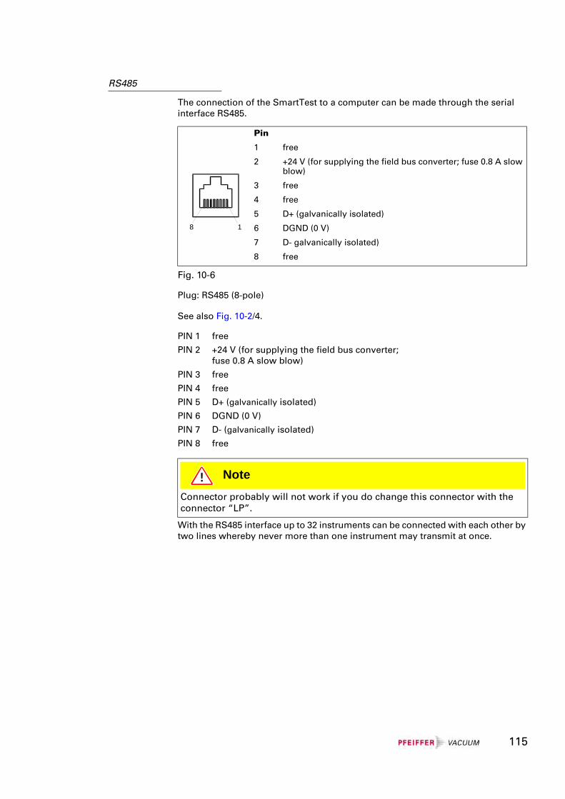
RS485
The connection of the SmartTest to a computer can be made through the serial interface RS485.
Plug: RS485 (8-pole)
See also Fig. 10-2/4.
With the RS485 interface up to 32 instruments can be connected with each other by two lines whereby never more than one instrument may transmit at once.
Pin
1
2
3
4
5
6
7
8
free
+24 V (for supplying the field bus converter; fuse 0.8 A slow blow)
free
free
D+ (galvanically isolated)
DGND (0 V)
D- galvanically isolated)
free
Fig. 10-6
PIN 1 free
PIN 2 +24 V (for supplying the field bus converter; fuse 0.8 A slow blow)
PIN 3 free
PIN 4 free
PIN 5 D+ (galvanically isolated)
PIN 6 DGND (0 V)
PIN 7 D- (galvanically isolated)
PIN 8 free
NoteConnector probably will not work if you do change this connector with the connector “LP”.
8 1
115
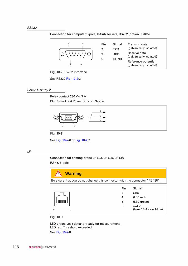
RS232
Connection for computer 9-pole, D-Sub sockets, RS232 (option RS485)
See RS232 Fig. 10-2/3.
Relay 1, Relay 2
Relay contact 230 V~, 3 A
Plug SmartTest Power Subcon, 3-pole
See Fig. 10-2/6 or Fig. 10-2/7.
LP
Connection for sniffing probe LP 503, LP 505, LP 510
RJ-45, 8-pole
LED green: Leak detector ready for measurement.LED red: Threshold exceeded.
See Fig. 10-2/8.
Pin
2
3
5
Signal
TXD
RXD
GGND
Transmit data(galvanically isolated)
Receive data(galvanically isolated)
Reference potential (galvanically isolated)
Fig. 10-7 RS232 interface
6
1
9
5
Fig. 10-8
1
23
3 1
WarningBe aware that you do not change this connector with the connector “RS485”.
Pin
3
4
5
6
Signal
zero
(LED red)
(LED green)
+24 V(fuse 0.8 A slow blow)
Fig. 10-9
8 1
116
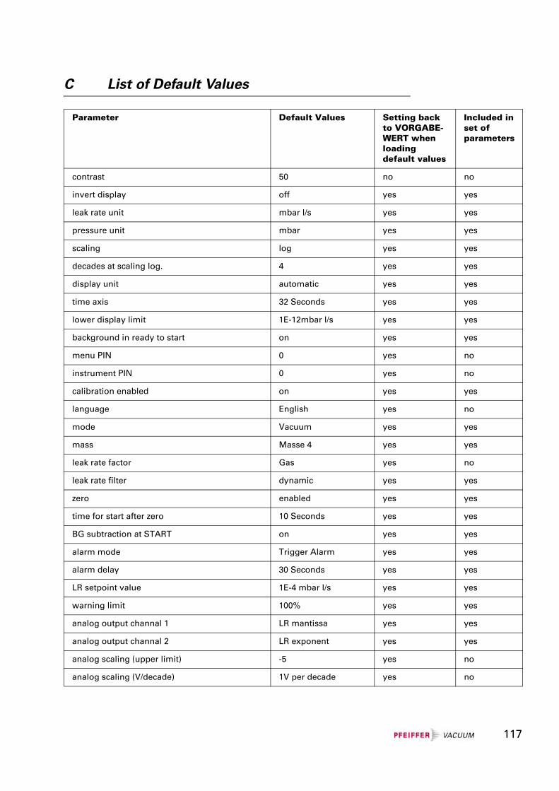
C List of Default Values
Parameter Default Values Setting back to VORGABE-WERT when loading default values
Included in set of parameters
contrast 50 no no
invert display off yes yes
leak rate unit mbar l/s yes yes
pressure unit mbar yes yes
scaling log yes yes
decades at scaling log. 4 yes yes
display unit automatic yes yes
time axis 32 Seconds yes yes
lower display limit 1E-12mbar l/s yes yes
background in ready to start on yes yes
menu PIN 0 yes no
instrument PIN 0 yes no
calibration enabled on yes yes
language English yes no
mode Vacuum yes yes
mass Masse 4 yes yes
leak rate factor Gas yes no
leak rate filter dynamic yes yes
zero enabled yes yes
time for start after zero 10 Seconds yes yes
BG subtraction at START on yes yes
alarm mode Trigger Alarm yes yes
alarm delay 30 Seconds yes yes
LR setpoint value 1E-4 mbar l/s yes yes
warning limit 100% yes yes
analog output channal 1 LR mantissa yes yes
analog output channal 2 LR exponent yes yes
analog scaling (upper limit) -5 yes no
analog scaling (V/decade) 1V per decade yes no
117
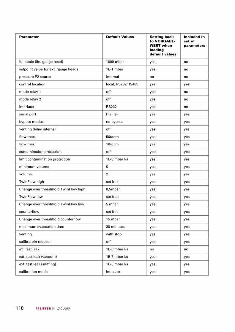
full scale (lin. gauge head) 1000 mbar yes no
setpoint value for ext. gauge heads 1E-1 mbar yes no
pressure P2 source internal no no
control location local, RS232/RS485 yes yes
mode relay 1 off yes no
mode relay 2 off yes no
interface RS232 yes no
serial port Pfeiffer yes yes
bypass modus no bypass yes yes
venting delay internal off yes yes
flow max. 50sccm yes yes
flow min. 10sccm yes yes
contamination protection off yes yes
limit contamination protection 1E-3 mbar l/s yes yes
minimum volume 0 yes yes
volume 2 yes yes
TwinFlow high set free yes yes
Change over threshhold TwinFlow high 0,5mbar yes yes
TwinFlow low set free yes yes
Change over threshhold TwinFlow low 5 mbar yes yes
counterflow set free yes yes
Change over threshhold counterflow 15 mbar yes yes
maximum evacuation time 30 minutes yes yes
venting with stop yes yes
calibratoin request off yes yes
int. test leak 1E-6 mbar l/s no no
ext. test leak (vacuum) 1E-7 mbar l/s yes yes
ext. test leak (sniffing) 1E-5 mbar l/s yes yes
calibration mode int. auto yes yes
Parameter Default Values Setting back to VORGABE-WERT when loading default values
Included in set of parameters
118
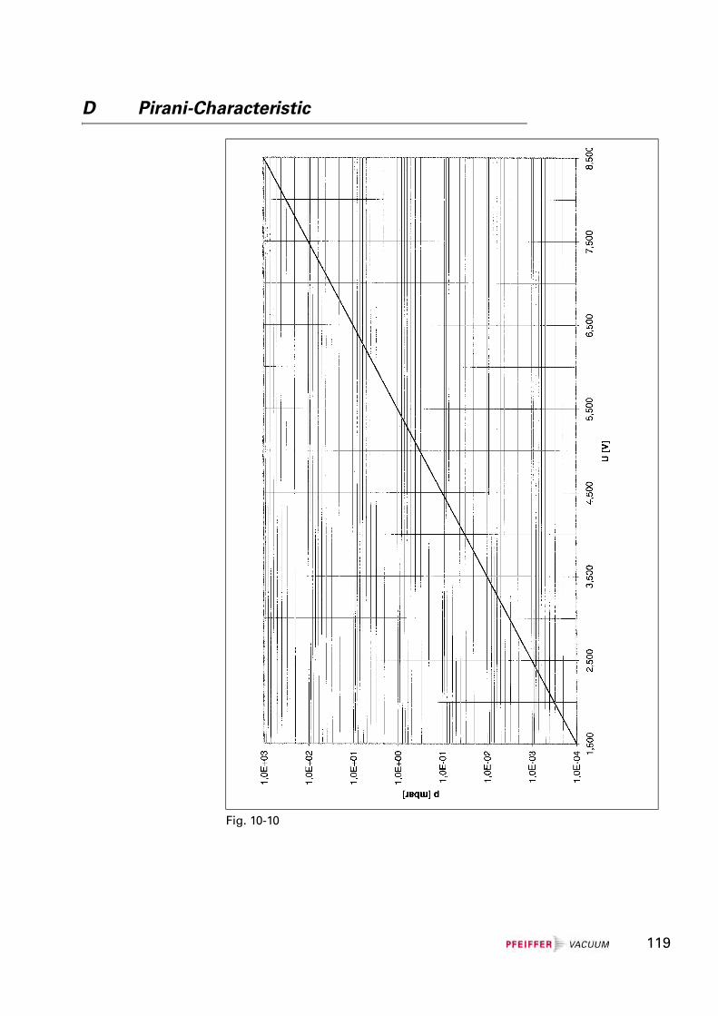
D Pirani-Characteristic
Fig. 10-10
119
E List of literature
Operating manual
Sniffer Probe LP 503, LP 505, LP 510
BG 805 268 BEN
Operating manual
Bypass-Option
PL0002 BN
Operating manual Cart for SmartTest
IG 0110 BEN
Communication Protocol SmartTest
IG 0105 BEN
Maintenance Instructions SmartTest
IG 0108 BEN
Operating instructions RC 500 WL / RC 500 IG 0140 BEN
F Declaration of Contamination
Fill in the form Declaration of Contamination before you ship a product to Pfeiffer Vacuum and enclose it to the shipment.
You can download the form on: http://www.pfeiffer-vacuum.net ..... from the Service-site.
WarningProducts returned to Pfeiffer Vacuum for service or repair must be free of harmful substances (e.g. radioactive, toxic, caustic or microbiological).
Forwarding contaminated products:
- Adhere to the forwarding regulations of all involved countries and forwarder companies.
- Enclose a completed Declaration of Contamination.
- Declare all dangers on the package.
Products which are not clearly declared as “free from potentially harmful substances” will be decontaminated at the expense of the customer.
120
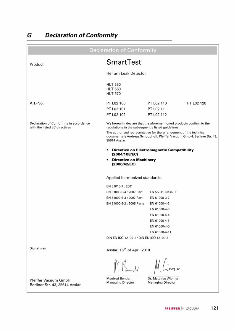
G Declaration of Conformity
Product SmartTestHelium Leak Detector
HLT 550HLT 560HLT 570
Art.-No. PT L02 100 PT L02 110 PT L02 120
PT L02 101 PT L02 111
PT L02 102 PT L02 112
Declaration of Conformity in accordance with the listed EC directives
We herewith declare that the aforementioned products confirm to the regulations in the subsequently listed guidelines.
The authorised representative for the arrangement of the technical documents is Andreas Schopphoff, Pfeiffer Vacuum GmbH, Berliner Str. 43, 35614 Asslar
• Directive on Electromagnetic Compatibility(2004/108/EC)
• Directive on Machinery(2006/42/EC)
Applied harmonized standards:
EN 61010-1 : 2001
EN 61000-6-4 : 2007 Part EN 55011 Class B
EN 61000-6-3 : 2007 Part EN 61000-3-2
EN 61000-6-2 : 2005 Parts EN 61000-4-2
EN 61000-4-3
EN 61000-4-4
EN 61000-4-5
EN 61000-4-6
EN 61000-4-11
DIN EN ISO 12100-1 / DIN EN ISO 12100-2
Signatures Asslar, 16th of April 2010
_______________________________ _____________________________
Pfeiffer Vacuum GmbHBerliner Str. 43, 35614 Asslar
Manfred BenderManaging Director
Dr. Matthias WiemerManaging Director
Declaration of Conformity
121

122

123

bH
a AB
G
m
You are looking for a perfect vacuum solution? Please contact us:
Leading. Dependable. Customer Friendly.
Pfeiffer Vacuum stands for innovative and custom vacuum solutions worldwide. For German engineering art,competent advice and reliable services.
Ever since the invention of the turbopump, we´ve been setting standards in our industry. And this claim to leadership will continue to drive us in the future.
GermanyPfeiffer Vacuum GmbH HeadquartersTel. +49 (0) 6441 [email protected]
Great BritainPfeiffer Vacuum Ltd.Tel.: +44 1908 [email protected]
AustriaPfeiffer Vacuum Austria GmTel.: +43 1 894 17 [email protected]
BeneluxPfeiffer Vacuum GmbHSales & Service BeneluxTel.: [email protected]
IndiaPfeiffer Vacuum India Ltd.Tel.: +91 40 2775 [email protected]
SwedenPfeiffer Vacuum ScandinaviTel.: +46 8 590 748 [email protected]
ChinaPfeiffer Vacuum (Shanghai) Co., Ltd.Tel.: +86 21 3393 [email protected]
ItalyPfeiffer Vacuum Italia S.p.A.Tel.: +39 02 93 99 05 [email protected]
SwitzerlandPfeiffer Vacuum (Schweiz) ATel.: +41 44 444 22 [email protected]
FrancePfeiffer Vacuum France SASTel.: +33 169 30 92 [email protected]
KoreaPfeiffer Vacuum Korea Ltd.Tel.: +82 31 266 [email protected]
United StatesPfeiffer Vacuum Inc.Tel.: +1 603 578 [email protected]
www.pfeiffer-vacuum.net


