24
Subject to technical modification Smarty 4X P_VP_P0116_AZ_0001 AHU WITH HEAT RECOVERY Smarty 4X P Control and Maintenance Manual

Subject to technical modification
Smarty 4X P_VP_P0116_AZ_0001
AHU WITH HEAT RECOVERY
Smarty 4X P
Control and Maintenance Manual

2
Smarty 4X P
www.salda.lt
Safety instructions and precautions 3Information about the product 4
Description 4Operating conditions 4Components 5Accessories Smarty 4X P 6Spare Parts Smarty 4X P 7
Device control 8Device control 8Meaning of the symbols used in the instructions and
on the device 8Descriptions of the functions 8Descriptions of Unit Functions 9System modes 10System Control 10System status 11Setting Date and Time 11Supply Air Temperature Control and Compensation 11 Fan Control 11“BOOST” Function 12Planing 12Winter/Summer Mode 12Protection against Dryness 12Night Cooling Function 13Chimney Sweep Function 13CO2 Reduction Function 13 Filter Protections 13Mode from an External System Contactor 13Fan Speeds from an External System Contactor 13Heat Exchanger Control 14System Monitoring 14Stand-By Mode Blocking 14Air Flow Adjustment 14Manual Control of Components 15Changing Passwords 15Restoring Factory Defaults 15Indications of Functions, Alarms and Warnings 15Display and Cancellation of Alarms and Warnings 15Event Log (History) 16System Versions and Running Time 16
Maintenance 17Cover opening 17Filters maintenance 17Heat exchanger maintenance 18Fans maintenance 18Bypass Dampers maintenance 20Control board maintenance 21Impulsinio maitinimo šaltinio priežiūra 21General recommendations for the maintenance of
ventilation system 22Possible faults and troubleshooting 22
Warranty 23Unit’s maintenance table 24

3
Smarty 4X P
www.salda.lt
Warning – pay attention Additional information
Stick the auxiliary label on the unit (on an easily accessible place) or on the dashed place of a technical manual in order to keep the important information about the unit.
STIC
K H
ERE
200003025238
IV
PV
KE
PE
M
0.084 kW; 0.92 A; 230/50 V/Hz; ~10.085 kW; 0.93 A; 230/50 V/Hz; ~1
kW; A; 0 V/Hz; ~0kW; A; 0 V/Hz; ~0
0.005 kW; 0.021 A; 24/50 V/Hz; ~-0.17 kW; 1.87 A; IP-34TOTAL:
gu072489 / 2014.03 www.salda.lt
1
3
4
5
2
6
200003025238
IV
PV
KE
PE
M
0.084 kW; 0.92 A; 230/50 V/Hz; ~10.085 kW; 0.93 A; 230/50 V/Hz; ~1
kW; A; 0 V/Hz; ~0kW; A; 0 V/Hz; ~0
0.005 kW; 0.021 A; 24/50 V/Hz; ~-0.17 kW; 1.87 A; IP-34TOTAL:
gu072489 / 2014.03 www.salda.lt
1
3
4
5
2
6
PAVYZDYS
EXAPLE
PAVADINIMAS
TITLE
M
200003025238
IV
PV
KE
PE
M
0.084 kW; 0.92 A; 230/50 V/Hz; ~10.085 kW; 0.93 A; 230/50 V/Hz; ~1
kW; A; 0 V/Hz; ~0kW; A; 0 V/Hz; ~0
0.005 kW; 0.021 A; 24/50 V/Hz; ~-0.17 kW; 1.87 A; IP-34TOTAL:
gu072489 / 2014.03 www.salda.lt
1
3
4
5
2
6
ESEMPIOTITOLO
200003025238
IV
PV
KE
PE
M
0.084 kW; 0.92 A; 230/50 V/Hz; ~10.085 kW; 0.93 A; 230/50 V/Hz; ~1
kW; A; 0 V/Hz; ~0kW; A; 0 V/Hz; ~0
0.005 kW; 0.021 A; 24/50 V/Hz; ~-0.17 kW; 1.87 A; IP-34TOTAL:
gu072489 / 2014.03 www.salda.lt
1
3
4
5
2
6
MUSTERTITEL
200003025238
IV
PV
KE
PE
M
0.084 kW; 0.92 A; 230/50 V/Hz; ~10.085 kW; 0.93 A; 230/50 V/Hz; ~1
kW; A; 0 V/Hz; ~0kW; A; 0 V/Hz; ~0
0.005 kW; 0.021 A; 24/50 V/Hz; ~-0.17 kW; 1.87 A; IP-34TOTAL:
gu072489 / 2014.03 www.salda.lt
1
3
4
5
2
6
ПPИМEPНАЗВАНИЕ
200003025238
IV
PV
KE
PE
M
0.084 kW; 0.92 A; 230/50 V/Hz; ~10.085 kW; 0.93 A; 230/50 V/Hz; ~1
kW; A; 0 V/Hz; ~0kW; A; 0 V/Hz; ~0
0.005 kW; 0.021 A; 24/50 V/Hz; ~-0.17 kW; 1.87 A; IP-34TOTAL:
gu072489 / 2014.03 www.salda.lt
1
3
4
5
2
6
PRZYKŁADTYTUŁ
1 – Logo2 – Internal usage code3 – Brand name4 – Technical data5 – Units number6 – Web address
Device is manufactured in compliance with the following directives:• Machinery Directive, 2006/42/EC;• Low Voltage Directive, EEC 2006/95;• Electromagnetic Compatibility Directive, 2004/108/EC.
Read this instruction very carefully before installing and using this equipment. Installation, connection and maintenance should be carried out by a qualified technician and in accordance with the local rules and legal acts.The company shall take no responsibility for the injuries suffered by the people or for the damaged property, if the safety requirements are not followed or the device is modified without the permission of the manufacturer.
Main safety rules
Danger• Before performing any electricity or maintenance tasks make sure, that the device is disconnected from the mains.• Before performing any installation or maintenance tasks, make sure that all moving parts of the device have stopped.• Make sure that the fans can not be entered through air ducts or branch openings.• If you notice liquids on electric parts or connections that bear voltage, stop the operation of the appliance.• Do not plug the device into the mains, that differs from the one indicated on the label or on the housing.• Voltage of the mains should comply with the electrotechnical parameters indicated on the label.• The device should be earthed in accordance with the rules of installation of electric appliances. It is forbidden to turn on and use
unearthed device. Follow the requirements of the device’s labels that indicate Danger.
Warnings• Connection of electricity and maintenance of the device should be performed only by a qualified personnel, in accordance with the
manufacturer’s instructions and valid safety requirements.• In order to reduce the risk during installation and maintenance, suitable protective clothes should be worn.• Beware of sharp angles while performing installation and maintenance tasks.• Do not touch heating elements until they haven’t cooled down.• Some devices are heavy, thus one should be very careful while transporting and installing. Use suitable lifting equipment.• While connecting electricity to the mains a circuit breaker of suitable size is necessary.
Warning!• If the device is installed in a cold environment, make sure that all connections and tubes are properly isolated. Intake and discharge
air ducts should be isolated in all cases.• Openings of the ducts should be covered during transportation and installation.• Do not connect humidity transducers to the ventilation system.
Before starting the equipment• make sure, that there are no strange objects inside;• manually check whether fans are not stuck or blocked;• if rotary heat exchanger is installed in the device, make sure that it is not stuck or blocked;• check the grounding;• make sure that all components and accessories are connected in accordance with the project or provided instructions.
Danger: FumesSalda Antifrost system uses dis-balancing of the air flow and it may cause negative pressure in premises. Great care should be taken when using at the same time in premises as another heating appliance what depend on the air in premises. Such appliances include gas, oil, wood or coal-fired boilers and heaters, fireplaces, continuous flow or other water heaters, gas hobs, cookers or ovens which draw air in from the room and duct exhaust gases out through a chimney or extraction ducting. The heating appliance can be starved of oxygen, impairing combustion. In exceptional cases harmful gases could be drawn out of the chimney or extraction ducting back into the room. In this case we strictly recommend to turn off Salda Antifrost and use an external preheater for heat exchanger anti-frost protection (see Salda Antifrost function on the Remote controller manual)

4
Smarty 4X P
www.salda.lt
Smarty 4X P are residential air handling unit with a high efficiency (up to 90 %) counter flow heat exchanger. The unit provides ventilation in the home and takes the heat from the exhausted air. AHU complies with ErP 2018. The unit is operated by a separate remote control panel or though separate MB-Gateway by PC. Remote control panel and MB-Gateway are optional and not included in standard package. Control functions depend on selected control board type: MiniMCB or MiniMCB basic.Smarty 4XP operates within the limits of the airflow diagrams and is suitable for indoor operation only. Required ambient temperatures must be from +5 oC to +40 oC. For the cold climate zones (air temperatures below -5 oC, integrated or optional pre-heater is required.
Not suitable for swimming pools, saunas and other similar facilities.
Prod
uct n
ame
Con
trol
boa
rd
Type
Hea
t rec
over
y
Tem
pera
ture
co
ntro
l
Byp
ass
dam
per
Pres
sure
sen
-so
r(fi
lter p
ollu
tion
mon
itorin
g)
Optional heating elements*- only pre-heater or heater
Duct based Air Pre-Heater
Duct based Air Heater
Smarty 4X P 1.1 Mini MCB Premium + + + + + +
Smarty 4X P 1.2 Mini MCB Basic Advanced + + + - +*
Thank you for purchasing the devices of our company!
* ‒ when relative humidity of extracted air is lower than 35 %.** ‒ uses dis-balancing of the air flow and it may cause negative pressure in premises.
Place of operation Indoors / outdoors / indoors and outdoors / outdoors with special accessories
Operation in explosive environment impossible
Transporting of the polluted air impossible
Outdoor air temeperature without preheater (Salda Antifrost** off) [°C] -5/+40*
Outdoor air temeperature without preheater (Salda Antifrost** on) [°C] -15/+40
Outdoor air temperature limits with a selected pre-heater on an air duct [°C] -30/+40
Outdoor air max humidity [%] 90
Temperature limits of an extracted air [°C] +15 / +40
Extract air max humidity [%] 60
5
Smarty 4X P
www.salda.lt
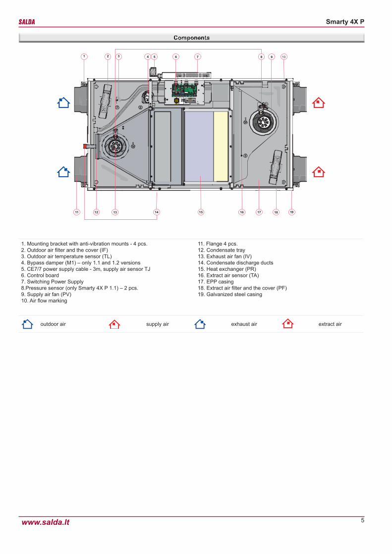
1. Mounting bracket with anti-vibration mounts - 4 pcs.2. Outdoor air filter and the cover (IF)3. Outdoor air temperature sensor (TL)4. Bypass damper (M1) ‒ only 1.1 and 1.2 versions5. CE7/7 power supply cable - 3m, supply air sensor TJ 6. Control board7. Switching Power Supply8.Pressure sensor (only Smarty 4X P 1.1) ‒ 2 pcs.9. Supply air fan (PV)10. Air flow marking
11. Flange 4 pcs.12. Condensate tray13. Exhaust air fan (IV)14. Condensate discharge ducts15. Heat exchanger (PR)16. Extract air sensor (TA)17. EPP casing18. Extract air filter and the cover (PF)19. Galvanized steel casing
outdoor air supply air exhaust air extract air

6
Smarty 4X P
www.salda.lt
WSG AKS SKG-A
MUTE Stouch MB Gateway
TE EKA EKA NIS
MAXI BLUE SET
S-KFF-U S-RFF-U-D-F2
S-KCO2 S-RCO2-F2 CM230-F-L
Smarty 4X P legs
MPL (G4) MPL (F7)
AP ALU IR24-P
PATROL-701 774451 + 774411
UG-3-A40 Incl VR-0,6M
Siphon D20
Supply and extract air gratingsWSG 160 GGRWSG0126_509
WSG 150 GGRWSG0126_508
DampersSKG-A 160 GSKSKG003
SKG-A 150 GSKSKG014
Actuator for damper CM230-F-L ZAKP0076
Temperature sensor TE PJUT0063
CO2 sensorsS-KCO2 ZAKKT0049
S-RCO2-F2 ZAKKT0048
Channel humidity transmitter S-KFF-U ZAKKT0051
Humidity transmitter RH S-RFF-U-D-F2 ZAKKT0050
Remote control panels Stouch PRGPU51
Net module MB Gateway PRGPU082
FiltersMPL (G4) ZFEPF109
MPL (F7)(pasirenkamas)
ZFEPF108
Legs Smarty 4X P legs GAGKS-MARTY168_1000
ClampsAP 150 GAPAP003
AP 160 GAPAP004
Ventilation grille ALU 160 GGRALU003
Condensate pump MAXI BLUE SET PRGSIK002
Electrical heaters
EKA 160-0,6-1f PSIEKA018
EKA NIS 160-0,6-1f PSIEKANIS81
EKA 160-1,0-1f PSIEKA031
EKA NIS 160-1,0-1f PSIEKANIS03
Electrical preheaters
EKA 160-1,0-1f PSIEKA031
EKA NIS 160-1,0-1f PSIEKANIS03
EKA 160-1,2-1f PSIEKA16003
EKA NIS 160-1,2-1f PSIEKANIS23
EKA 160-2.4-1f PSIEKA16005
EKA NIS 160-2,4-1f PSIEKANIS24
EKA 160-5.0-2f PSIEKA16007
EKA NIS 160-5,0-2F PSIEKANIS27
Silencers
AKS 150-6 GSOAKS064
AKS 150-9 GSOAKS048
AKS 150-10 GSOAKS106
AKS 150-12 GSOAKS086
MUTE 160x600 GSOMUTE010
MUTE 160x900 GSOMUTE012
AKS 160-10 GSOAKS029
MUTE 160x1200 GSOMUTE013
Siphon Siphon D20 GKIS001
Duct smoke detector UG-3-A4O incl VR-0,6M ZAKKT0110
Switch 774451+774411 ZEPSM001
Motion detector PATROL-701 ZAKJT021
Ceiling presence detector IR24-PC ZAKJT020
Wall presence detector IR24-P ZAKJT019

7
Smarty 4X P
www.salda.lt
Heat exchanger Heat exchanger ZSLPLGS0020
Door Door Smarty 2X P GPUD232_1002_0
Supply air fan Fan GPUVM224_1061_1061
Extract air fan Fan GPUVM224_1062_1061
Bypass damper By-pass(tik Smarty 4X P 1.1, 1.2) GPUSK227_1001_1021
Control boards
MiniMCB(tik Smarty 4X P 1.1) GAUSM219_1042_1063
MiniMCB basic(tik Smarty 4X P 1.2) GAUSM219_1042_1071
Temperature sensor 1,5 m TL/TA PJUT0062
Temperature sensor 3 m TJ PJUT0063
Circulation damper’s drive with a string of wires, tips and sealants
15 D SEE-202(tik Smarty 4X P 1.1, 1.2) GPYSM221_0_1055
Switching Power Supply G2 ZED01008
Heat ex-changer
Door Smarty 4X P
Fan
By-pass MiniMCB MiniMCB basic
TL/TA TJ 15 D SEE-202
G2

8
Smarty 4X P
www.salda.lt
Ventilation unit can be controlled using a remote control, web interface via MB-Gateway and building management system. More information about the possibilities of controlling is provided in the table below.
Stouch MB-Gateway BMS
+ + Modbus RTU
outdoor air supply air exhaust air extract air
FunctionsSmarty 4X P 1.1 Smarty 4X P 1.2
MiniMCB MiniMCB basic
Date and time settings ● ●
System modes for easy and-user friedly control (Stand-by, Building protection, Economy, Comfort)
● ●
BOOST function (Fans operate at highst speed) ● ●
Comfortable air temperature function ● ●
Cold/heat recovery ● ●
Fire place function ● -
Heating season (from a selected date, 3-day temperature average or manually) ● ●
Dryness protection ○ ○ 1
Weekly/holiday schedule ● ●
User and service control levels ● ●
Automatic air flow balancing (using integrated pressure transducers) ● -
Manual air flow balancing ● ●
CO2 level indication and reduction function ○ ○ 1
Night cooling function ● ●
Relative humidity (RH) level indication and reduction function ○ ○ 1
Software and configuration update possibility ● ●
Supply air temperature control according to the extract air sensor ● ●
Monitoring function (all sensors and I/O) ● ●
Mode switch (start/stop) ● ●
Manual components control ● ●
Switching the speed of the fans ● ●
Functional units
Fans
Soft start and stop ● ●
Fan failure protection ● 2 ● 2
Protection by RPM ● 2 ● 2
Protection by pressure ● -
Speed synchronous/asynchronous 0-10V control ● ●
Electrical heater
On/off/PWM control ● ● 3
Manual protection ● ● 3
Automatic protection ● ● 3
Overheat protection (additional protection software) ● ● 3
9
Smarty 4X P
www.salda.lt
Control board functions and logics are designed according to Standards DIN 1946-6:2009-05 and EN 12098-3.MCB control board can be controlled by: Ptouch remote control panel, Stouch remote control panel or MB - GATEWAY web application. Description of remote control panel functions is provided in the remote control panel technical documentation or on the website www.salda.lt.
Air Handling Unit uses two types of boards, depending on the selected product version: miniMCB or miniMCB basic. Their functionality is different, thus check the board name by the product version.
The unit can be configured only with Ptouch remote control panel or MB-Gateway web application.The following control board functions can be fully controlled only with Ptouch remote control panel or MB-Gateway web application. In case of Stouch remote control panel use the description of remote control panel functions for MCB control board.
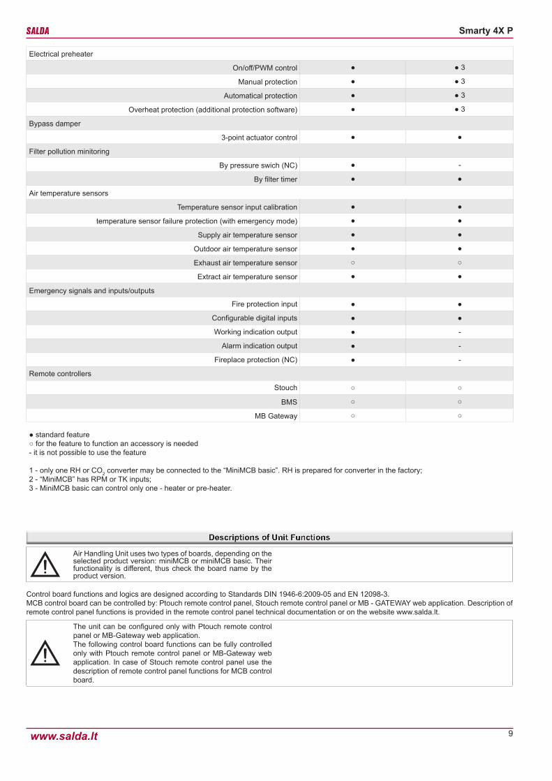
Electrical preheater
On/off/PWM control ● ● 3
Manual protection ● ● 3
Automatical protection ● ● 3
Overheat protection (additional protection software) ● ● 3
Bypass damper
3-point actuator control ● ●
Filter pollution minitoring
By pressure swich (NC) ● -
By filter timer ● ●
Air temperature sensors
Temperature sensor input calibration ● ●
temperature sensor failure protection (with emergency mode) ● ●
Supply air temperature sensor ● ●
Outdoor air temperature sensor ● ●
Exhaust air temperature sensor ○ ○
Extract air temperature sensor ● ●
Emergency signals and inputs/outputs
Fire protection input ● ●
Configurable digital inputs ● ●
Working indication output ● -
Alarm indication output ● -
Fireplace protection (NC) ● -
Remote controllers
Stouch ○ ○
BMS ○ ○
MB Gateway ○ ○
● standard feature○ for the feature to function an accessory is needed- it is not possible to use the feature
1 - only one RH or CO2 converter may be connected to the “MiniMCB basic”. RH is prepared for converter in the factory;2 - “MiniMCB” has RPM or TK inputs;3 - MiniMCB basic can control only one - heater or pre-heater.

10
Smarty 4X P
www.salda.lt
System modes:• Stand-by• Building protection• Economy• Comfort
In stand-by mode the system is shut down for a permissible shutdown period (based on the stand-by mode blocking function settings).The building protection mode is designed to protect a building against moisture accumulation. In this mode the system operates at speed 1. By default, in this mode temperature maintenance is controlled (preferred temperature is indicated). However, if necessary, temperature maintenance can be switched off.Economy mode is designed to save energy when people are not in the room. In this mode the system operates at speed 2. By default, in this mode temperature maintenance is controlled (preferred temperature is indicated). However, if necessary, temperature maintenance can be switched off.Comfort mode is used when people are present in the room. In this mode the system operates at speed 3. In this mode the temperature is always maintained.
System mode can be changed automatically by the functions (in a sequential order as indicated):1 - Weekly Schedule2 - Mode is activated from an external contactor3 - User’s manual mode selection4 - Holiday Schedule5 - Stand-by mode blocking
Based on the weekly schedule the system decides which mode it will be operating in; however, the user may change the existing mode manually. The system will inform when the next mode change is scheduled. After power loss the mode is selected based on the weekly schedule; however, if the schedule is not set, the mode used before the power loss will be activated.The user may change modes only when the mode is activated from an external contactor. The only case when the user cannot change the mode is when the period of a holiday schedule is active. The system informs that the holiday schedule mode is active. To prevent blocking, the period of the holiday schedule must be changed.Stand-by mode can be blocked based on selected parameters. If at least one of the above functions changes its mode into stand-by mode, it must be checked whether this mode is not currently blocked. If it is blocked, the previous selected mode is on.The function order is provided below.
User entered data.
Reading of inputdata
Data sending to outputs and user interface
Weekly Schedule
Mode external switch
Holiday Schedule
Stand-by mode block-ing
Protection against Dryness
Boost ventilation
Ventilation logics
Protections
Ventilation logics blocking
Manual control of com-ponents
Start
End
11
Smarty 4X P
www.salda.lt
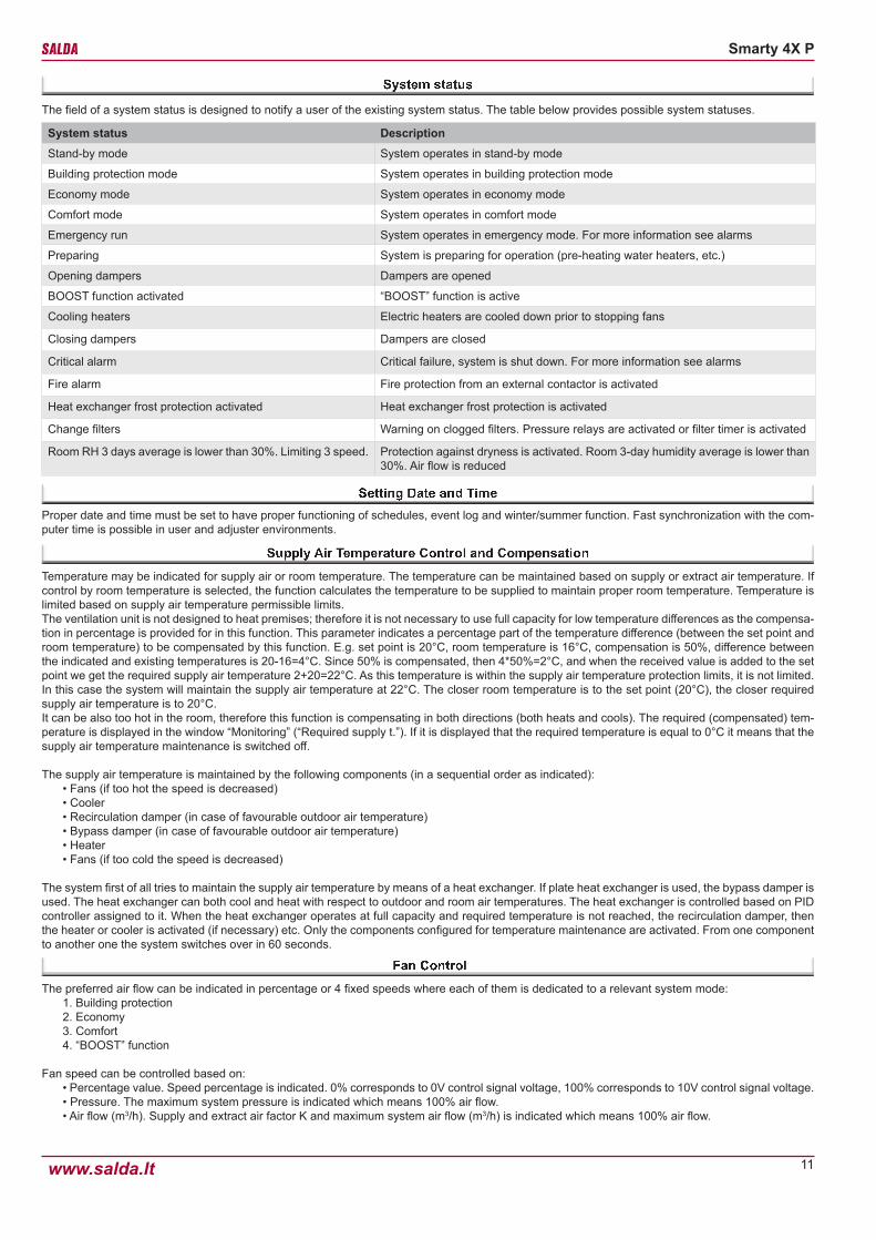
The field of a system status is designed to notify a user of the existing system status. The table below provides possible system statuses.
System status DescriptionStand-by mode System operates in stand-by mode
Building protection mode System operates in building protection mode
Economy mode System operates in economy mode
Comfort mode System operates in comfort mode
Emergency run System operates in emergency mode. For more information see alarms
Preparing System is preparing for operation (pre-heating water heaters, etc.)
Opening dampers Dampers are opened
BOOST function activated “BOOST” function is active
Cooling heaters Electric heaters are cooled down prior to stopping fans
Closing dampers Dampers are closed
Critical alarm Critical failure, system is shut down. For more information see alarms
Fire alarm Fire protection from an external contactor is activated
Heat exchanger frost protection activated Heat exchanger frost protection is activated
Change filters Warning on clogged filters. Pressure relays are activated or filter timer is activated
Room RH 3 days average is lower than 30%. Limiting 3 speed. Protection against dryness is activated. Room 3-day humidity average is lower than 30%. Air flow is reduced
Proper date and time must be set to have proper functioning of schedules, event log and winter/summer function. Fast synchronization with the com-puter time is possible in user and adjuster environments.
Temperature may be indicated for supply air or room temperature. The temperature can be maintained based on supply or extract air temperature. If control by room temperature is selected, the function calculates the temperature to be supplied to maintain proper room temperature. Temperature is limited based on supply air temperature permissible limits.The ventilation unit is not designed to heat premises; therefore it is not necessary to use full capacity for low temperature differences as the compensa-tion in percentage is provided for in this function. This parameter indicates a percentage part of the temperature difference (between the set point and room temperature) to be compensated by this function. E.g. set point is 20°C, room temperature is 16°C, compensation is 50%, difference between the indicated and existing temperatures is 20-16=4°C. Since 50% is compensated, then 4*50%=2°C, and when the received value is added to the set point we get the required supply air temperature 2+20=22°C. As this temperature is within the supply air temperature protection limits, it is not limited. In this case the system will maintain the supply air temperature at 22°C. The closer room temperature is to the set point (20°C), the closer required supply air temperature is to 20°C.It can be also too hot in the room, therefore this function is compensating in both directions (both heats and cools). The required (compensated) tem-perature is displayed in the window “Monitoring” (“Required supply t.”). If it is displayed that the required temperature is equal to 0°C it means that the supply air temperature maintenance is switched off.
The supply air temperature is maintained by the following components (in a sequential order as indicated):• Fans (if too hot the speed is decreased)• Cooler• Recirculation damper (in case of favourable outdoor air temperature)• Bypass damper (in case of favourable outdoor air temperature)• Heater• Fans (if too cold the speed is decreased)
The system first of all tries to maintain the supply air temperature by means of a heat exchanger. If plate heat exchanger is used, the bypass damper is used. The heat exchanger can both cool and heat with respect to outdoor and room air temperatures. The heat exchanger is controlled based on PID controller assigned to it. When the heat exchanger operates at full capacity and required temperature is not reached, the recirculation damper, then the heater or cooler is activated (if necessary) etc. Only the components configured for temperature maintenance are activated. From one component to another one the system switches over in 60 seconds.
The preferred air flow can be indicated in percentage or 4 fixed speeds where each of them is dedicated to a relevant system mode:1. Building protection2. Economy3. Comfort4. “BOOST” function
Fan speed can be controlled based on:• Percentage value. Speed percentage is indicated. 0% corresponds to 0V control signal voltage, 100% corresponds to 10V control signal voltage.• Pressure. The maximum system pressure is indicated which means 100% air flow.• Air flow (m3/h). Supply and extract air factor K and maximum system air flow (m3/h) is indicated which means 100% air flow.

12
Smarty 4X P
www.salda.lt
Boost ventilation function is used for fast ventilation of the rooms. This function activates the maximum air flow (speed 4). Boost ventilation must be temporary, i.e. it must be a final condition (e.g. CO2 limit, time). The reason for this limitation is protection against dryness. The function is activated manually and from the external system contactor.The function is inactive in stand-by mode. Time limit shall be set to this function. Once the function is activated, the indicated time is set for the function timer and time is counted till the function deactivation. This time may be adjusted in real-time, i.e. when the function is on.
The winter/summer function is used to set upcoming cold periods, because some part of the system need to be protected against cold outdoor air. During the winter period it is recommended to leave the unit on, therefore it is possible to set that the system switch-off is blocked during the winter period. Water heaters must be always on during the entire winter period.
The winter mode may be indicated:• Manually• By date• Based on 3-day mean outdoor air temperature. The mean is calculated only when the fresh air (outdoor) pre-heater is off.
This function is designed to protected premises against dryness. If the function is active, it calculates the 3-day mean humidity of extract air from the premises. If the mean drops below 30%, fans start operating at speed 2 in comfort mode. A user is notified of the activated protection and limited air flow.If the humidity mean exceeds 30% or the function is switched off manually, fans start operating at speed 3 in comfort mode.
Weekly Schedule
A weekly schedule consists of 10 weekly events. They can be added, deleted, activated and deactivated. One event indicates time, mode and days of the week.The system changes modes based on the weekly schedule only when the indicated time comes; therefore a user can always change the existing mode manually. This schedule notifies the user of the upcoming mode change by indicating the time remaining till the next event.
Holiday Schedule
A holiday schedule is used when the unit has to operate in an indicated mode during holidays. The user interface shows when the schedule period is active as the mode activated by this function (except for protections) can be changed by no-one. In order to control the system in a normal manner, the holiday schedule period must be deactivated, i.e. zero values must be indicated or period dates must be changed. Up to five holiday periods can be indicated.
The fans are controlled by PID controller based on air flow and pressure. Every fan is controlled individually.It is possible to limit the minimum and maximum fan control signal voltage. By default, minimum 2V voltage is indicated which means that 0V voltage signal is sent when fans are off, and 2V voltage signal is immediately sent when rotation is required.
Fan Protection based on Rotating Speed
If fans have “tacho” outputs, the fan failure can be identified based on their rotating speed. If the system sends the signal for fans to rotate and they fail to rotate, then protection is activated, system operation is shut down and alarm is displayed.
Air Flow Protection based on Pressure (only Smarty 4X P 1.1)
Where this protection is activated the system must reach the required pressure or air flow. If the system fails to reach the required air flow or pressure within the indicated period of time, the protection is activated, unit is shut down and alarm is displayed. This may happen due to failures of air flow/pressure transmitters, pressure hose defect, clogged flow, impeller defects, incorrect factor K, etc.
Protection of Premises with a Fireplace (only Smarty 4X P 1.1)
This protection is used for premises with a fireplace. It protects against improper air pressure difference which can result in presence of flue gas (carbon black) in premises. Pressure switch must be connected to the assigned digital input to measure pressure drop in the premises and inside the chimney. Upon activation of this protection the pressure switch will shut down the unit and display the alarm.
Slowing Down Air Flows based on Temperature
If supply air temperature is more important than air flow, the function of air flow slowing down based on temperature may be switched on. If full heat-ing/cooling capacity is used to reach the desired temperature and it is not reached, the air flow is slowed down to have sufficient power to maintain the desired temperature.
Continuous Temperature Maintenance by Slowing Fans Down
This function is designed to save energy when air flow is changed. It is active when fans are controlled based on percentage, since PID controllers do it automatically if it is controlled based on air flows or pressure. Fast change of air flows imbalances the temperature maintenance function and consumes energy until it is balanced again. If a user sets a higher air flow, this function starts gradually increasing the air flow and gradually slows down the conversion speed when it approaches the set value. In this way the temperature maintenance function suffers less stress and consumes less energy. If the user reduces the air flow, the system switches off coolers and heaters to prevent from the heat/cold wave and gradually changes the air flow. After the air flow has been reduced, heaters and coolers continue operating as required.

13
Smarty 4X P
www.salda.lt
This function is designed to save energy which is used to cool a building in the morning by cool night air.
If the function is on but not active, activation conditions are checked:1 - System time is between function start and function end (hours/minutes).2 - Time is every hour since the start.3 - If “Stand-by” mode is set, the unit operates in “Building protection” for 5 minutes so that the actual temperature data is available. Temperatures
are checked after purging. If wrong temperatures are received the unit returns to “Stand-by” mode.4 - Outdoor temperature is higher than the set outdoor temperature.5 - Extract air temperature is higher than the set temperature.6 - Extract air temperature is higher than the outdoor temperature by at least 2 °C.7 - Summer time.
If all conditions are fulfilled the unit starts operating in “Comfort” mode (without temperature maintenance). The main window shows that the night cooling function is active.
Where the function is active, the deactivation conditions are regularly checked:1 - Time does not correspond to the start/end interval.2 - Extract air temperature drops below the set point.3 - Outdoor air temperature drops below the set point.4 - Mode other than “Comfort” was switched or the unit has been shut down
If at least one condition is correct, the unit switches off the night cooling function and it switches to the mode that was on prior to activating the function.
When the function of fan speed from an external contactor is used, the function can be adjusted so that it helps to light a fire in a fireplace. The external contactor may be connected to the switch of the fireplace door. It must be indicated in the function that “On/Off” signal will be used, minimum extract air fan speed and maximum supply air fan speed must be indicated. This combination will create the pressure in a room, which will improve the smoke extract through a chimney as well as burning. When the fireplace door is opened, the function will be activated. When the door is closed, the function will be deactivated.
This function is designed to maintain a proper quality of room air.Where CO2 exceeds the permissible limit, CO2 reduction is activated and air flow is increased. When CO2 reaches the set point, this function is switched off.
Filter Timer Settings
Filter timer limit is set to the function. The maximum setting can be 1 year.
Air Filter Protections based on Pressure Relays
The function checks if the filters are clogged by means of pressure switches. Available function operating combinations:• Not available• Supply air• Extract air• Supply and extract air
When pressure switches are activated an alarm is displayed.
This function is designed to activate the preferred system mode by means of an external contactor. The function indicates a type of a signal to be sent to the input.
Possible types of signals:• Not used• Button click. Selected system mode is activated. Function is activated when it receives an impulse. It is deactivated when it receives the impulse
again.• On/off. Selected system mode is activated. Mode is active when contactor is on.• PIR sensor. When the sensor is activated, the selected system mode is activated. If the signal is not received within 30 minutes, the mode is
deactivated.
This function is designed to activate/deactivate the boost ventilation function or preferred combination of fan speeds by means of an external contactor. The function indicates a type of a signal to be sent to the input and components controlled by it. Possible combinations of signal types and functions:
• Not used.• On/off. Selected fan speed combination is activated. Function is on when contactor is on.• Button click. Selected fan speed combination is activated. Function is activated when it receives an impulse. It is deactivated when it receives
the impulse again.• On/off. Boost ventilation function is controlled. Function is on when contactor is on. If the boost ventilation function is not terminated by means of
this function within the boost ventilation time limit, force shutdown is used after the time expires.• Button click. Boost ventilation function is controlled. Function is activated when it receives an impulse. It is deactivated when it receives the
impulse again. • If the boost ventilation function is not terminated by means of this function within the boost ventilation time limit, force shutdown is used after the
time expires.
14
Smarty 4X P
www.salda.lt
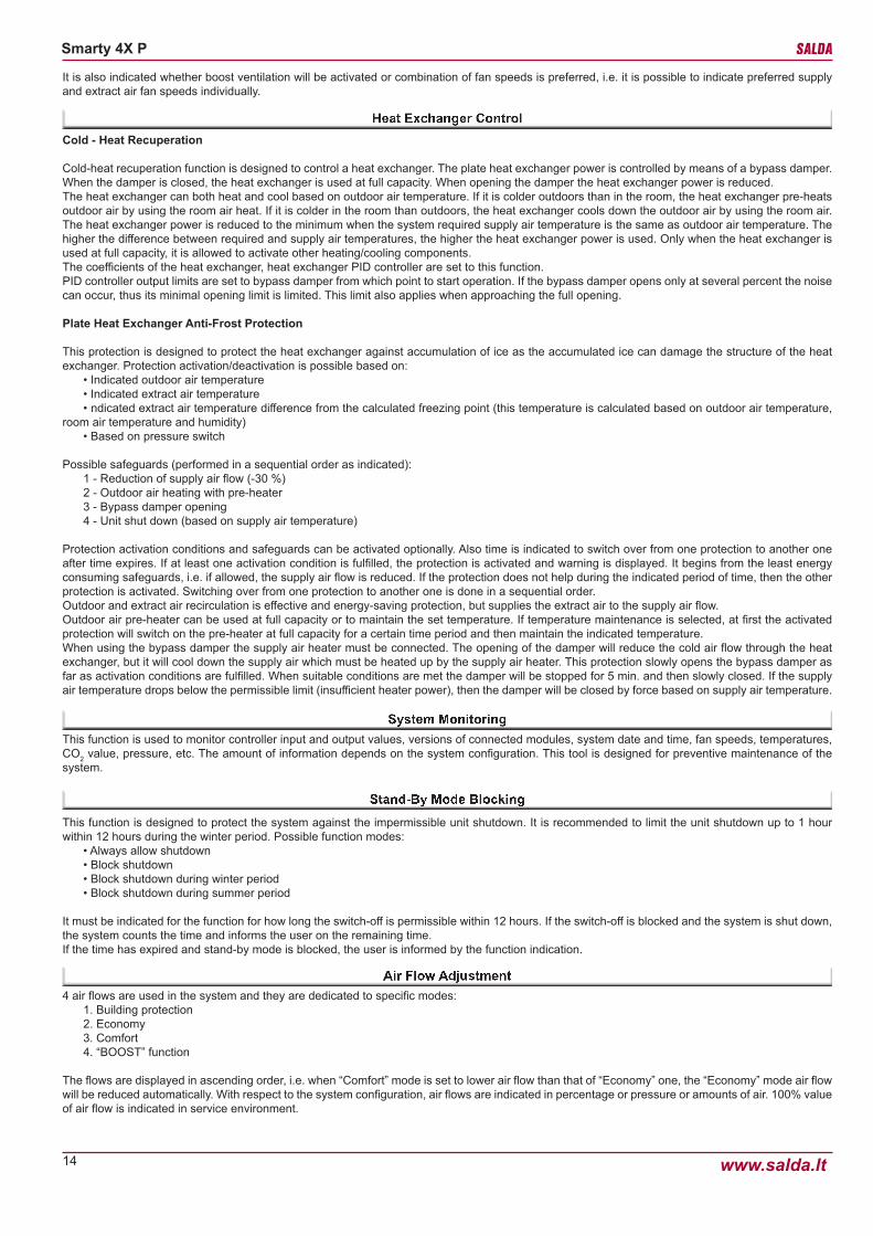
Cold - Heat Recuperation
Cold-heat recuperation function is designed to control a heat exchanger. The plate heat exchanger power is controlled by means of a bypass damper. When the damper is closed, the heat exchanger is used at full capacity. When opening the damper the heat exchanger power is reduced.The heat exchanger can both heat and cool based on outdoor air temperature. If it is colder outdoors than in the room, the heat exchanger pre-heats outdoor air by using the room air heat. If it is colder in the room than outdoors, the heat exchanger cools down the outdoor air by using the room air. The heat exchanger power is reduced to the minimum when the system required supply air temperature is the same as outdoor air temperature. The higher the difference between required and supply air temperatures, the higher the heat exchanger power is used. Only when the heat exchanger is used at full capacity, it is allowed to activate other heating/cooling components.The coefficients of the heat exchanger, heat exchanger PID controller are set to this function.PID controller output limits are set to bypass damper from which point to start operation. If the bypass damper opens only at several percent the noise can occur, thus its minimal opening limit is limited. This limit also applies when approaching the full opening.
Plate Heat Exchanger Anti-Frost Protection
This protection is designed to protect the heat exchanger against accumulation of ice as the accumulated ice can damage the structure of the heat exchanger. Protection activation/deactivation is possible based on:
• Indicated outdoor air temperature• Indicated extract air temperature• ndicated extract air temperature difference from the calculated freezing point (this temperature is calculated based on outdoor air temperature,
room air temperature and humidity)• Based on pressure switch
Possible safeguards (performed in a sequential order as indicated):1 - Reduction of supply air flow (-30 %)2 - Outdoor air heating with pre-heater3 - Bypass damper opening4 - Unit shut down (based on supply air temperature)
Protection activation conditions and safeguards can be activated optionally. Also time is indicated to switch over from one protection to another one after time expires. If at least one activation condition is fulfilled, the protection is activated and warning is displayed. It begins from the least energy consuming safeguards, i.e. if allowed, the supply air flow is reduced. If the protection does not help during the indicated period of time, then the other protection is activated. Switching over from one protection to another one is done in a sequential order.Outdoor and extract air recirculation is effective and energy-saving protection, but supplies the extract air to the supply air flow.Outdoor air pre-heater can be used at full capacity or to maintain the set temperature. If temperature maintenance is selected, at first the activated protection will switch on the pre-heater at full capacity for a certain time period and then maintain the indicated temperature.When using the bypass damper the supply air heater must be connected. The opening of the damper will reduce the cold air flow through the heat exchanger, but it will cool down the supply air which must be heated up by the supply air heater. This protection slowly opens the bypass damper as far as activation conditions are fulfilled. When suitable conditions are met the damper will be stopped for 5 min. and then slowly closed. If the supply air temperature drops below the permissible limit (insufficient heater power), then the damper will be closed by force based on supply air temperature.
This function is used to monitor controller input and output values, versions of connected modules, system date and time, fan speeds, temperatures, CO2 value, pressure, etc. The amount of information depends on the system configuration. This tool is designed for preventive maintenance of the system.
This function is designed to protect the system against the impermissible unit shutdown. It is recommended to limit the unit shutdown up to 1 hour within 12 hours during the winter period. Possible function modes:
• Always allow shutdown• Block shutdown• Block shutdown during winter period• Block shutdown during summer period
It must be indicated for the function for how long the switch-off is permissible within 12 hours. If the switch-off is blocked and the system is shut down, the system counts the time and informs the user on the remaining time.If the time has expired and stand-by mode is blocked, the user is informed by the function indication.
4 air flows are used in the system and they are dedicated to specific modes:1. Building protection2. Economy3. Comfort4. “BOOST” function
The flows are displayed in ascending order, i.e. when “Comfort” mode is set to lower air flow than that of “Economy” one, the “Economy” mode air flow will be reduced automatically. With respect to the system configuration, air flows are indicated in percentage or pressure or amounts of air. 100% value of air flow is indicated in service environment.
It is also indicated whether boost ventilation will be activated or combination of fan speeds is preferred, i.e. it is possible to indicate preferred supply and extract air fan speeds individually.
15
Smarty 4X P
www.salda.lt
The function of manual control of components is designed to activate/deactivate the components manually. Components are controlled by digital and analogue outputs. Analogue outputs are controlled in percentage, and digital output are controlled by “on/off”. By default, all components are attributed “Auto” status which means that a component is controlled based on ventilation logic. Components are displayed by the system configuration. Settings must be saved so that they remain the same after power loss.The minimum unit consumption in stand-by mode is ensured only when all the manual control components are set to “Auto” position.Prior to using the manual control function, it is recommended to activate the force shutdown function which blocks the ventilation logic functions.This function may be useful, if you need to check whether everything is properly connected. Moreover, in the event of failure, certain component can be activated so that the unit operates irrespective of sensors and protections. Of course, this method should be applied in exceptional cases until the failure is rectified.If an external (“Remote”) type of a temperature sensor is displayed, the sensor temperature may be indicated manually, and the values may be indi-cated via the Modbus interface.
Login passwords can be changed in the service environment. To change passwords of service and adjuster environments the password must be activated.The password consists of 4 digits. If password is not necessary for parameter review and change, set the password (number “0”).
This function allows to restore the factory defaults.
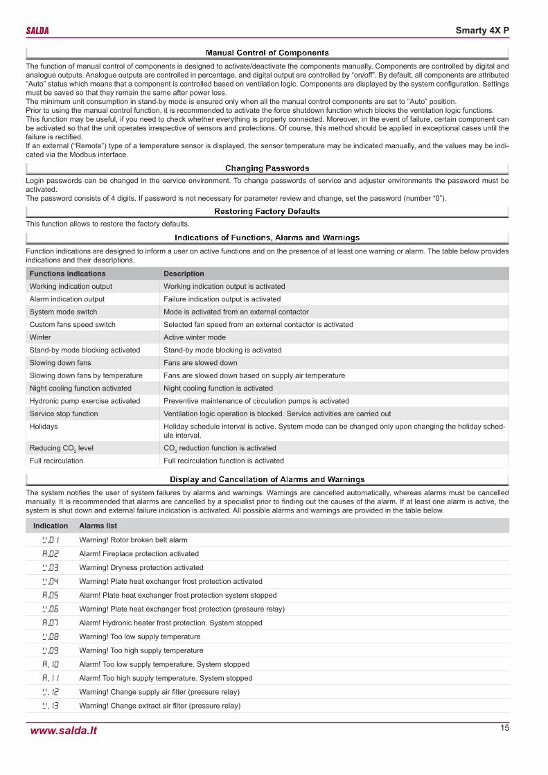
Function indications are designed to inform a user on active functions and on the presence of at least one warning or alarm. The table below provides indications and their descriptions.
Functions indications DescriptionWorking indication output Working indication output is activated
Alarm indication output Failure indication output is activated
System mode switch Mode is activated from an external contactor
Custom fans speed switch Selected fan speed from an external contactor is activated
Winter Active winter mode
Stand-by mode blocking activated Stand-by mode blocking is activated
Slowing down fans Fans are slowed down
Slowing down fans by temperature Fans are slowed down based on supply air temperature
Night cooling function activated Night cooling function is activated
Hydronic pump exercise activated Preventive maintenance of circulation pumps is activated
Service stop function Ventilation logic operation is blocked. Service activities are carried out
Holidays Holiday schedule interval is active. System mode can be changed only upon changing the holiday sched-ule interval.
Reducing CO2 level CO2 reduction function is activated
Full recirculation Full recirculation function is activated
The system notifies the user of system failures by alarms and warnings. Warnings are cancelled automatically, whereas alarms must be cancelled manually. It is recommended that alarms are cancelled by a specialist prior to finding out the causes of the alarm. If at least one alarm is active, the system is shut down and external failure indication is activated. All possible alarms and warnings are provided in the table below.
Indication Alarms list
. Warning! Rotor broken belt alarm
A.2 Alarm! Fireplace protection activated
. Warning! Dryness protection activated
. Warning! Plate heat exchanger frost protection activated
A.5 Alarm! Plate heat exchanger frost protection system stopped
.6 Warning! Plate heat exchanger frost protection (pressure relay)
A.7 Alarm! Hydronic heater frost protection. System stopped
. Warning! Too low supply temperature
. Warning! Too high supply temperature
A. Alarm! Too low supply temperature. System stopped
A. Alarm! Too high supply temperature. System stopped
.2 Warning! Change supply air filter (pressure relay)
. Warning! Change extract air filter (pressure relay)
16
Smarty 4X P
www.salda.lt
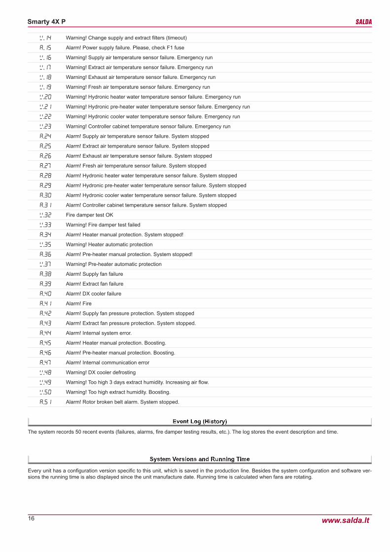
The system records 50 recent events (failures, alarms, fire damper testing results, etc.). The log stores the event description and time.
Every unit has a configuration version specific to this unit, which is saved in the production line. Besides the system configuration and software ver-sions the running time is also displayed since the unit manufacture date. Running time is calculated when fans are rotating.
. Warning! Change supply and extract filters (timeout)
A.5 Alarm! Power supply failure. Please, check F1 fuse
.6 Warning! Supply air temperature sensor failure. Emergency run
.7 Warning! Extract air temperature sensor failure. Emergency run
. Warning! Exhaust air temperature sensor failure. Emergency run
. Warning! Fresh air temperature sensor failure. Emergency run
.2 Warning! Hydronic heater water temperature sensor failure. Emergency run
.2 Warning! Hydronic pre-heater water temperature sensor failure. Emergency run
.22 Warning! Hydronic cooler water temperature sensor failure. Emergency run
.2 Warning! Controller cabinet temperature sensor failure. Emergency run
A.2 Alarm! Supply air temperature sensor failure. System stopped
A.25 Alarm! Extract air temperature sensor failure. System stopped
A.26 Alarm! Exhaust air temperature sensor failure. System stopped
A.27 Alarm! Fresh air temperature sensor failure. System stopped
A.2 Alarm! Hydronic heater water temperature sensor failure. System stopped
A.2 Alarm! Hydronic pre-heater water temperature sensor failure. System stopped
A. Alarm! Hydronic cooler water temperature sensor failure. System stopped
A. Alarm! Controller cabinet temperature sensor failure. System stopped
.2 Fire damper test OK
. Warning! Fire damper test failed
A. Alarm! Heater manual protection. System stopped!
.5 Warning! Heater automatic protection
A.6 Alarm! Pre-heater manual protection. System stopped!
.7 Warning! Pre-heater automatic protection
A. Alarm! Supply fan failure
A. Alarm! Extract fan failure
A. Alarm! DX cooler failure
A. Alarm! Fire
A.2 Alarm! Supply fan pressure protection. System stopped
A. Alarm! Extract fan pressure protection. System stopped.
A. Alarm! Internal system error.
A.5 Alarm! Heater manual protection. Boosting.
A.6 Alarm! Pre-heater manual protection. Boosting.
A.7 Alarm! Internal communication error
. Warning! DX cooler defrosting
. Warning! Too high 3 days extract humidity. Increasing air flow.
.5 Warning! Too high extract humidity. Boosting.
A.5 Alarm! Rotor broken belt alarm. System stopped.
17
Smarty 4X P
www.salda.lt
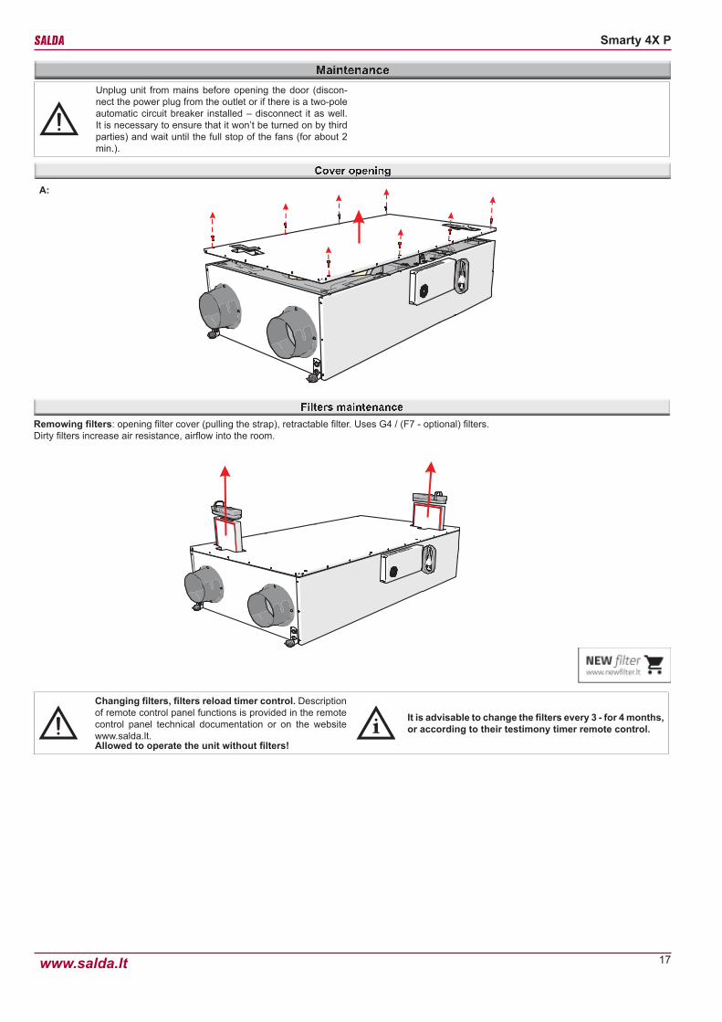
Unplug unit from mains before opening the door (discon-nect the power plug from the outlet or if there is a two-pole automatic circuit breaker installed – disconnect it as well. It is necessary to ensure that it won’t be turned on by third parties) and wait until the full stop of the fans (for about 2 min.).
Remowing filters: opening filter cover (pulling the strap), retractable filter. Uses G4 / (F7 - optional) filters.Dirty filters increase air resistance, airflow into the room.
Changing filters, filters reload timer control. Description of remote control panel functions is provided in the remote control panel technical documentation or on the website www.salda.lt.Allowed to operate the unit without filters!
It is advisable to change the filters every 3 - for 4 months, or according to their testimony timer remote control.
A:

18
Smarty 4X P
www.salda.lt
• Maintenance should be performed only by experienced and trained staff.• The fan should be inspected and cleaned at least once a year. • Be sure the fan is disconnected from power source before performing any maintenance or repair.• Observe staff safety regulations during maintenance and repair.• The motor is of heavy duty ball bearing construction. The motor is completely sealed and requires no lubrication. Supplied air fan from X2, X4. Extract
air fan from X2, X4.• Detach fan from the unit.• Impeller should be specially checked for buil-up material or dirt which may cause an imbalance. Excessive imbalance can lead to accelerated wear
on motor bearings and vibration.• Clean impeller and inside housing with mild detergent, water and damp, soft cloth.• Do not use high pressure cleaner, abrasives, sharp instruments or caustic solvents that may scratch or damage housing and impeller.• Do not plunge the motor into any fluid while cleaning impeller.• Make sure, that impeller’s balance weights are not moved.• Make sure the impeller is not hindered.• Mount the fan back into the unit. Connect the fan to power supply source.• If after maintenance the fan does not start or stop itself, contact the producer. Malfunction of the fan can be identified according to the pressure in the
system (when pressure switches are connected). When there is a folt in fans’ motor, any separate notice is shown on the control panel.
Be sure the unit is disconnected from power source before performing any maintenance or repair.
• Proceed to maintenance and repair after any rotation in the fan stopped.• Clean the heat exchanger once a year.• Firstly take out heat exchanger cassette carefully. Submerge it into a bath and wash with warm soapy water (do not use soda). Then rinse it with
weak hot water stream (too strong stream can fold the plates). Place back the heat exchanger only when it is completely dry.
B:
NOTE. Before performing action B, actions A should be performed.
1 2

19
Smarty 4X P
www.salda.lt
• Remove the fan connectors from the control board. Supplied air fan from X2, X4. Extract air fan from X2, X4.• Fan power cables are connected directly to a 48 VDC power supply.• Remove steel cover by unscrewing 4 bolts in order to access power supply unit.• Disconnect blue and red fan power cables from the power supply unit.
DRAWN BY
CHECKED BY
SIGNATUREDUTIES / NAME DATE
UAB"SALDA" Drawing #
Book #
CHECKED BY
1 1 2 3 4 4 5 6 7 7
EI A. ŠklenikasEI K. Vasiliauskas224.1061E
SP54
Principle connection scheme
1
01
2016.06.142016.06.142016.06.14
BK - Black - JuodasBN - Brown - RudasGY - Grey - PilkasWH - White - BaltasBU - Blue - MėlynasRD - Red - RaudonasGN/YE - Green/Yellow - Žalias/Geltonas
48VD
C
0-10
V
Tach
o
GN
D
48VD
C
0-10
V
Tach
o
GN
D
1 2 3 654-X2 KF2EDGKD-2.5/6P
1 2 3 654
-X4 KF2EDGKD-2.5/6P
PV IV
-G2
- +
-G2
- -
-G2
- +
-G2
- -
Viol
et0.
75
Whi
te0.
75
Blue
0.75
Red
0.75
Viol
et0.
75
Whi
te0.
75
Blue
0.75
Red
0.75
BK BN GY WH BU RD GN/YE
black Brown Grey White Blue Red Green/Yelow
20
Smarty 4X P
www.salda.lt
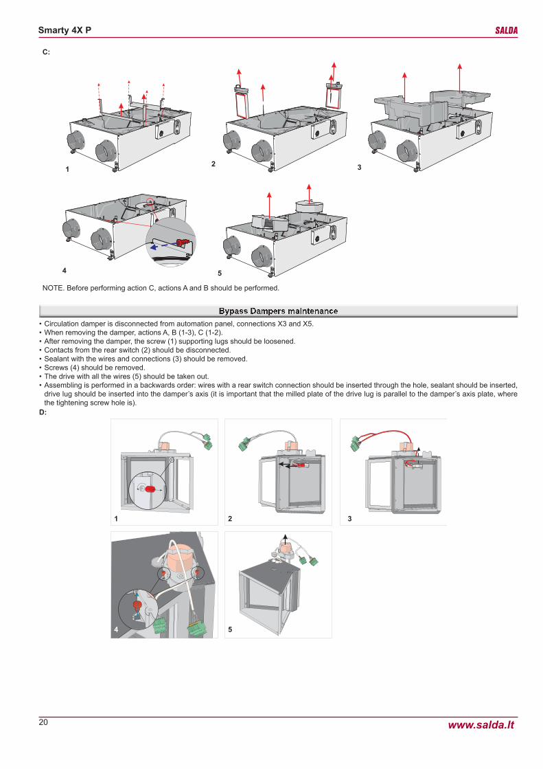
• Circulation damper is disconnected from automation panel, connections X3 and X5.• When removing the damper, actions A, B (1-3), C (1-2).• After removing the damper, the screw (1) supporting lugs should be loosened.• Contacts from the rear switch (2) should be disconnected.• Sealant with the wires and connections (3) should be removed.• Screws (4) should be removed.• The drive with all the wires (5) should be taken out.• Assembling is performed in a backwards order: wires with a rear switch connection should be inserted through the hole, sealant should be inserted,
drive lug should be inserted into the damper’s axis (it is important that the milled plate of the drive lug is parallel to the damper’s axis plate, where the tightening screw hole is).
1 2 3
4 5
D:
C:
12 3
4 5
NOTE. Before performing action C, actions A and B should be performed.

21
Smarty 4X P
www.salda.lt
- Loosen the front screw, that tightens automation sole to the housing of the device.- Disconnect the connections from the automation panel and the hoses from the pressure converters (“Smarty 4X P” 1.1).- Remove automation through the front part.- Connections are marked in accordance with the place of their connection, thus, while assembling, pay attention to the marking of connection place of the connections and controllers. If the marking on a controllers connections can not be seen, use the PCB information provided in this passport (see the description of “mini MCB”).E:
21
NOTE. Before performing action E, actions A should be performed.

22
Smarty 4X P
www.salda.lt
In order to ensure proper functioning of the system, maintenance requirements and its periods should be followed. Otherwise the warranty shall not be valid. Some recommendations are provided in the table below, but they are just advisory, as the need of system maintenance depends on the place of the device installation, the pollution of the atmosphere, the population, the working hours and etc.
Component During start-up At least every 6 monthsFilter Check the cleanliness of the filters Change filters
Fans Check the connections and the direction of ro-tation
Check cleanliness. Clean, if necessary
Rotor Check the direction of rotation Check cleanliness and clean, if necessary
Check the tension of a belt
Heat exchanger Check the cleanliness of the heat exchanger Check cleanliness and clean, if necessary
Control panel Check the connections Check the connections
Electrical heater Check the connections Clean the dust
Whater heater Check the tightness Check cleanliness and clean, if necessary
Check the tightness and seal the connections, if necessary
Condensate discharge trap Clean
Presure sensor Check the connection of electricity Check the operation
Temperature sensor Check the connection of electricity Check the operation and tune up, if necessary
Air intake and discharge system Check the connections Clean
Air duct system Check the tightness Clean
Dampers, diffusers, grid Check the tightness of connections Clean
Failure Cause Explanation / corrective actions
Unit is not operating No supply voltages Check whether the device is connected to the plug socket
Two-pole protection device is off or a current leakage relay is active (if installed by the in-staller)
Switch on only if the unit condition has been evaluated by a qualified electrician. If the sys-tem failed, the failure MUST BE rectified prior to switching it on.
Air supply heater or heater is not operating or malfunctioning (if installed)
Too low air flow in air ducts activates automatic protection
Check if air filters are not cloggedCheck if fans are rotating
Manual protection is activatedPossible heater or unit failure. MUST address the servicing staff for failure detection and its elimination.
Too low air flow at rated fan speed Clogged supply and/or extract air filter(s) Filter replacement needed
Filters are clogged and no message is shown on the remote control Wrong time in filter timers Shorten filter timer time till the message of
clogged filters
23
Smarty 4X P
www.salda.lt
1. All equipment manufactured in our factory is checked in operating conditions and tested befor delivery. Test protocol is supplied together with the unit. The equipment is shipped in good working order and condition to the direct client. The unit is warrantied for the period of two years from the invoice date.2. If equipment is found to have been damaged during transportation, a claim should be made against carrier, as we assume no responsibility for such damage.3. This warranty does not apply:
3.1. when transportation, storage, installation and maintenance instructions of the unit are violated;3.2. when the equipment is improperly maintained, mounted - inadequate maintenance; 3.3. when the equipment without our knowledge and permission has been upgraded or unskilled repairs were made;3.4. when the unit was used not for its original purpose.
4. This warranty does not apply at these malfunction cases:4.1. mechanical damage; 4.2. damage caused by entering outside objects, materials, liquids; 4.3. damage caused by natural disaster, accident (voltage change in the electricity network, lightning, etc..).
5. The company assumes no liability for its products either directly or indirectly damage, if the damage is caused by failure to comply with installation and mounting regulations, deliberate or careless users or third-party behavior.
These conditions are readily discernable when the equipment is returned to our factory for inspection.If the direct client determines that equipment is found to be faulty, or a breakdown occurred, he should inform the manufacturer within five working days and deliver the equipment to manufacturer. Delivery costs should be covered by customer.

24
Smarty 4X P
www.salda.lt
IntervalD
ate
Instalation
Fan cleaningO
nce a year
Heat exchanger cleaning
Once a year
Filter replacement
Every 3-4 months
NO
TE. The purchaser is required to fill in the “Product maintenance table”.
*2
- At least.*
2 -Look at the product label.*
1
Product name
gu/lu number
*1
*1
*2
*2
Improvem
ents and changes to this manual necessitated by typographical errors, inaccuracies of current inform
ation, or improvem
ents to programs and/or equipm
ent, may be m
ade by the manufacturer at
any time and w
ithout notice. Such changes will, how
ever, be incorporated into new editions of this m
anual. All illustrations are for illustrative purposes only and may not accurately depict the actual device.


