SMBUS COMMUNICATION FOR SMALL FORM FACTOR DEVICE FAMILIES
1. Introduction
C8051F3xx and C8051F41x devices are equipped withan SMBus serial I/O peripheral that is compliant withboth the System Management Bus Specification and theI2C-Bus Specification. The SMBus is a bi-directional, 2-wire interface capable of communication with multipledevices. A typical SMBus configuration is shown inFigure 1. SMBus is a trademark of Intel; I2C is atrademark of Phillips Semiconductor.
This application note describes the SMBusspecification, how to configure and use the on-chipSMBus interface, and SMBus debugging techniques.Code examples written in C provide the generalframework for most SMBus Master and Slaveimplementations. An example that interfaces to a 256-byte EEPROM over a two-wire interface and supportsmulti-byte transfers is also included at the end of thisnote.
2. Overview of the SMBus Specification
The SMBus Specification describes the electricalcharacteristics, network control conventions andcommunications protocols used by SMBus devices. TheSMBus Specification can be downloaded fromwww.smbus.org. The I2C Specification can bedownloaded from www.philipslogic.com/i2c/.
2.1. SMBus StructureAn SMBus system is a 2-wire network in which eachdevice has a unique address and may be addressed byany other device on the network. All transfers areinitiated by a “Master” device; if a device recognizes itsown address and responds, it becomes the “Slave”device for that transfer. It is important to note thatassigning one specified Master device is not necessary.Any device may assume the role of Master or Slave forany particular transfer. In the case that two devicesattempt to initiate a transfer simultaneously, anarbitration scheme forces one device to give up the bus.This arbitration scheme is non-destructive (one devicewins and no information is lost). Arbitration is discussedin depth in the Arbitration section of this note.
Two wires are used in SMBus communication: SDA(serial data) and SCL (serial clock). Each line is bi-directional, with the direction depending on which modeeach of the devices is in. The Master always drivesSCL; either device may drive SDA. Both lines should beconnected to a positive power supply through a pull-upcircuit. All devices on the SMBus line should have open-drain or open collector outputs, so that the lines mayremain high when the bus is free. A line is pulled low ifone or more devices attempts to output a LOW signal.All devices must output a HIGH for the line to stay high.
2.2. HandshakingSMBus employs various line conditions as handshakingbetween devices. Note that during a data transfer, SDAis only allowed to change levels while SCL is low.Figure 2 illustrates the handshaking signals. Changeson SDA while SCL is high represent START and STOPsignals, as follows:
START: This initiates a transfer. It consists of a fallingedge on SDA while SCL is high.
STOP: This ends a transfer. It consists of a rising edgeon SDA while SCL is high.
ACKNOWLEDGE: Also referred to as an “ACK”, thishandshaking signal is transmitted by a receiving deviceas a confirmation. For example, after device_X receivesa byte, it transmits an ACK to confirm the transfer. AnACK consists of a low level on SDA sampled when SCLis high.
NOT_ACKNOWLEDGE: Also referred to as a “NACK”,this handshaking signal is a high level on SDA sampledwhen SCL is high. When a receiving device fails toACK, the sending device sees a NACK. In typicaltransfers, a received NACK indicates that theaddressed Slave is not ready for transfer, or is notpresent on the bus. A receiving Master may transmit aNACK to indicate the last byte of a transfer. Both ofthese situations are discussed further in the nextsection.
SLAVE ADDRESS + R/W: This handshaking signal issent after the START signal on a new transfer. Thesignal is sent in an 8-bit transfer by the Master; 7address bits and 1 Read/Write (R/W) bit. The addressedSlave should decode the (R/W) bit to determine the typeof the current transfer. The (R/W) bit is set to logic 1 toindicate a “READ” operation and cleared to logic 0 toindicate a “WRITE” operation.
2.3. Transfer ModesTwo types of transfers are possible: a WRITE (transferfrom Master to Slave) and a READ (transfer from Slaveto Master). During a transfer, any device may assumeone of four roles: Master Transmitter, Master Receiver,Slave Receiver, or Slave Transmitter.
2.3.1. Master Transmitter
In this role, the device transmits serial data on SDA anddrives the clock on SCL. The device initiates thetransfer with a START, sends the Slave Address + W,and waits for an ACK from the Slave. After the ACK isreceived, the device transmits one or more bytes ofdata, with each byte ACK’ed by the Slave. After the lastbyte, the device transmits a STOP.
2.3.2. Master Receiver
In this role, the device receives serial data on SDA whiledriving the clock on SCL. The device initiates thetransfer with a START followed by the Slave Address +R. After the Slave ACK’s its address, the device willoutput the clock on SCL and receive data on SDA. Afterreceiving the last byte, the device will issue a NACKfollowed by a STOP.
2.3.3. Slave Transmitter
In this role, the device outputs serial data on SDA andreceives the clock on SCL. The device receives aSTART followed by its own Slave Address + R, thenACK’s its address and enters Slave Transmitter mode.The device transmits serial data on SDA and receivesan ACK after each byte. After the last byte has beensent, the Master will issue a NACK followed by a STOP.
2.3.4. Slave Receiver
In this role, the device receives serial data on SDA andthe clock on SCL. The device receives a STARTfollowed by its own Slave Address + W from a Master,then ACK’s its address and enters Slave Receivermode. The device receives serial data on SDA and theclock on SCL. The device ACK’s each byte receivedand exits Slave mode after the Master issues a STOP.
Figure 2. SMBus Timing
SLA6SDA
SLA5-0 R/W D7 D6-0
SCL
Slave Address + R/W Data ByteSTART ACK NACK STOP
AN141
Rev. 1.3 3
2.4. Typical WRITE Scenarios Example (1) in Figure 3 shows a successful transfer when the device is operating as a Master Transmitter.
2.4.1. Slave Address NACK’ed
In Example (2), the Master receives a NACK after sending the Slave Address + W. This occurs when a Slave is‘off line’, meaning it is not responding to its own address. The Master has the option of transmitting a STOP and togive up the transfer or a repeated START to retry the transfer. To send a repeated START, the Master sends aSTOP followed by a START and Slave Address + W. The Master will repeat the cycle until it receives an ACK. Thisis referred to as “acknowledge polling”.
2.4.2. Reserving the Bus with a Repeated START
In Example (3), the Master issues a repeated START after an ACK. This process allows the Master to initiate a newtransfer without giving up the bus (to switch from a WRITE to a READ, for example). The repeated START iscommonly used in EEPROM memory access applications, where a memory READ must be directly preceded by aWRITE indicating the desired memory location. The repeated START is demonstrated in the EEPROM codeexample at the end of this note.
Figure 3. Typical WRITE Transfer Scenarios
From Slaveto Master
NACK received after SLA + W PN(2)
(3) Repeat start issued after Acknowledge ASLA + RS
(4) NACK received after data PN
S = StartSLA = Slave Address (7 bits)W = Write (1 bit)R = Read (1 bit)Data = Serial data (8 bits)A = AcknowledgeN= Not-AcknowledgeP = Stop
Successful WRITE S SLA + W A Data PA AData(1)
Any number of databytes and acknowledges
From Masterto Slave
Data
AN141
4 Rev. 1.3
2.5. Data Byte NACK’edIn Example (4), the master receives a NACK after sending a data byte. In typical SMBus systems, this is how thereceiving device indicates an error. The Master sends a STOP, and retries the transfer as in Example (2), or givesup the transfer. Note that the use of NACKs is not restricted to error situations; the acknowledge level is a user-definable characteristic, and may vary in different applications.
2.6. Typical READ ScenariosExample (1) in Figure 4 shows a successful READ operation when the device is operating as a Master Receiver.
2.6.1. Slave Address NACK’ed
In Example (2), the Master receives a NACK after sending the Slave Address + R. This situation is handled in thesame fashion as in Example (2) of the WRITE discussion. The Master can use acknowledge polling to retry thetransfer, or can give up the transfer.
2.6.2. Changing Direction (Read/Write) with a Repeated START
Example (3) shows the Master sending a repeated START after sending a byte of data. This is the same repeatedSTART state as in the WRITE discussion. A Master may send a repeated START after any data byte, and mayinitiate a READ or a WRITE following the repeated START. Generally a repeated START is used to changedirection (READ/WRITE) or to change addresses (Slave devices).
2.7. Other SMBus ScenariosNote that the READ and WRITE diagrams show only the typical scenarios. Bus errors, timeouts, and arbitration arealso possible occurrences. Timeouts are used to detect when a transfer has stalled or when the bus is free. Anydevice may hold SCL low until it is ready to continue a transfer. This process allows a slower Slave device tocommunicate with a faster Master, since stalling the bus effectively reduces the SCL frequency. The SMBusprotocol specifies that all devices on the SMBus must declare any SCL signal held low for more than 25 ms a“timeout”. When a timeout occurs, all devices on the bus must reset communication. A high SCL timeout is alsopossible. If both SDA and SCL remain high for more than 50 µsec, the bus is designated as free.
Figure 4. Typical READ Scenarios
S = StartSLA = Slave Address (7 bits)W = Write (1 bit)R = Read (1 bit)Data = Serial data (8 bits)A = AcknowledgeN = Not-AcknowledgeP = Stop
From Slaveto Master
Any number of databytes and acknowledges
From Masterto Slave
Data
NACK received after SLA + R PN(2)
(3) Repeat start issued after ACK ASLA + RS
Successful READ(1) S SLA + R A Data PA NData
AN141
Rev. 1.3 5
2.8. ArbitrationIf multiple Masters are configured on the same SMBus system, it is possible that two will attempt to initiate atransfer at the same time. If this happens, an arbitration scheme is employed to force one device to give up thebus.
The arbitration works as follows: both Masters continue to transmit until one attempts a HIGH “recessive bit” whilethe other attempts a LOW “dominant bit”. Due to the open-drain bus, the device attempting a LOW will win the bus.The device sending a HIGH gives up the bus, and the other device continues its transfer. Note that the collision isnon-destructive: one device always wins.
Figure 5 shows an example output sequence between two devices during arbitration. Assume Master Device_Xand Master Device_Y contend for the bus. The winner, Device_X, is not affected at all by the arbitration. Since datais shifted into the SMBus data register as it is shifted out, Device_Y does not miss any data. Note that Device_Yswitches to Slave mode after losing arbitration and will respond to Device_X if addressed.
Figure 5. Arbitration Sequence
Device_Y
Device_X01 1 1 0 1 1 0
01 1 1 1
01 1 1 0 1 1 0Seen on the Bus
Device_Ygives upthe bus
AN141
6 Rev. 1.3
3. Using the SMBus with the C8051F3xx and C8051F41x
The SMBus peripheral can operate in both Master andSlave modes and provides shifting control for the serialtransfers. Timing for baud rate generation and SCL Lowtimeout is provided by the on-chip timers. All otherprotocol requirements are implemented by interrupt-driven user software.
3.1. SMBus Management TasksThe following tasks should be implemented by anydevice participating in an SMBus network. They areperformed using SMBus hardware and user software.
3.1.1. SCL Clock Generation
When configured as an SMBus Master, the hardwaregenerates the clock signal on SCL based on Timer 0,Timer 1, Timer 2 high byte, or Timer 2 low byteoverflows. The maximum SCL frequency in Mastermode is approximately one third the overflow rate of theselected timer. The SMBus baud rate selected shouldnot exceed 1/10 of the system clock frequency.
3.1.2. SCL Low Timeout (C8051F30x)
The SCL Low Timeout, when enabled, uses Timer 2 todetect if SCL has been low for more than 25 ms. It isimportant to keep SCL from staying low for long periodsof time because no other devices can use the busduring this time. The SCL Low Timeout is onlyapplicable when operating as a Master.
The SCL Low Timeout logic works by forcing Timer 2 toreload when SCL is high, and allowing it to count whenSCL is low. Timer 2 should be enabled and configuredto overflow after a 25 ms interval. The Timer 2 interruptservice routine can be used to reset (disable and re-enable) the SMBus in the event of an SCL Low Timeout.
3.1.3. SCL Low Timeout (All Other Devices)
The SCL Low Timeout on all devices other than theC8051F30x uses Timer 3 instead of Timer 2, butoperates exactly as in the C8051F30x.
3.1.4. Arbitration Lost Detection
In the SMBus arbitration system, one master alwayswins and no data is lost. However, arbitration can still belost for various reasons: another device on the busillegally tampers with SDA or SCL, or environmentalnoise is enough to cause false rising or falling edges.The automatic arbitration lost detection bit, ARBLOST,in the SMB0CN register will be set if:
A repeated START is detected as a MASTER when the STA bit is set to '0' (unwanted repeated START).
SCL is sensed low while attempting to generate a
STOP or repeated START condition (MASTER).
SDA is sensed low while transmitting a ‘1’ (excluding ACK bits) (SLAVE or MASTER).
The SMBus ISR should check for a set ARBLOST bitand act accordingly. In the case of the example SMBusMaster and Slave programs discussed later, a setARBLOST bit is handled by resetting the SMBusmodule, ignoring the erroneous data transmission, andcontinuing with the next transmission. The ARBLOSTbit is automatically cleared by hardware when theSMBus interrupt flag (SI) is cleared by software (end ofthe ISR).
3.1.5. Serial Data Transfers
The hardware controls all shifting of data on the SDAsignal. Acknowledgments are managed by usersoftware, as explained in the register definitions below.
3.1.6. Slave Address Recognition
Slave Address recognition is handled by user software.If the Slave inhibit bit (SMB0CF.6) is not set, the SMBusinterface issues an interrupt each time a Slave Addressis detected on the bus. The Slave Address appears inthe SMB0DAT register and is decoded by the ISR. If thedevice recognizes the address, it should acknowledge itby setting the ACK bit. Otherwise, it should clear theACK bit to send a NACK.
3.2. Configuration and ControlThe SMBus interface can operate as a Master or aSlave. A device enters Master mode upon writing a ‘1’to the STA (START) bit. A Master device is responsiblefor generating the clock signal for the entire transfer.When the device is not in Master mode, it is a Slave andwill receive interrupts from the SMBus interface whentraffic is detected on the bus. The Slave Inhibit bit(SMB0CF.6) allows the device to go “offline” to avoidgetting interrupted when network traffic is detected. In“offline” mode, the hardware will automatically NACK alltransfers initiated by other devices on the bus. Mastermode transfers are not affected by the Slave Inhibit bit.
Below is a brief description of the SMBus registers andhow they affect device operation. For more detailedinformation, see the SMBus chapter in the Silicon Labsdevice data sheet.
SMB0CF. The SMBus configuration register is used toenable the SMBus interface and select whether SlaveMode is enabled or inhibited. It is also used to select theSCK time base and enable the SCL Low Timeout.
SMB0CN. The SMBus control register is used as astatus indicator and to send SMBus START and STOPsignals. This register is also used to define the outgoingACK level and read incoming ACK levels. The ACK bit
AN141
Rev. 1.3 7
in this register should be written each time a byte isreceived and read each time a byte is transmitted.
SMB0DAT. The SMBus Data Register is used to holddata and Slave Addresses. When transmitting orreceiving a 7-bit Slave Address, the least significant bitof the SMB0DAT register is used as a direction bit toindicate whether the transfer is a read or a write. Dataread from this register is only valid while SI = 1. WhenSI is not set, software should not try to access theregister because the SMBus interface may be in theprocess of shifting data. Note that in Master mode,data will not be shifted in or out if the STA or STObits are set. Instead, START or STOP signals will begenerated, respectively.
3.3. SMBus CommunicationAll SMBus communication is handled by the SMBusinterrupt service routine (ISR). The SMBus ISR can beimplemented as a state machine that takes inputparameters from the SMB0CN register and from statevariables. The state definitions and typical responseoptions for the various states are located in Table 1 onpage 20 (C8051F30x) and Table 2 on page 22 (all othersupported devices). Note that in these tables, the upperfour bits of SMB0CN are referred to as the ‘statusvector’.
The implementation of the SMBus ISR will varyaccording to application-specific needs. The followingexamples provide the general framework necessary touse the supported C8051F3xx and C8051F41x devicesin the following modes:
Master Transmitter
Master Receiver
Slave Receiver
Slave Transmitter
An additional EEPROM example that supports multi-byte transfers is provided to demonstrate how thegeneral framework can be customized to suit anapplication-specific need. The software for the 'F33x isprovided at the end of this application note. Additionalexamples for all supported devices are available uponrequest.
3.3.1. Writing Data to an SMBus Slave (Master Transmitter)
An SMBus device in Master Transmitter mode maywrite one or more bytes to a Slave. The following stepsand the flowchart in Figure 6 show how the examplesoftware initiates a transfer to a to a Slave Receiver inpolled code:
1. Software Busy Flag? The <SMB_BUSY> flag is a
software managed flag that keeps another transfer from starting before the current transfer is complete. This flag is cleared by the SMBus ISR after a transfer is complete.
2. Claim SMBus. Set the <SMB_BUSY> flag. No other transfers can be initiated while this flag is set to ‘1’.
3. Set global parameters. The global parameters include an <SMB_RW> flag specifying whether the transfer is a read or a write. They also include the outgoing data byte <SMB_DATA_OUT> and the target Slave Address <TARGET>.
4. Send START Signal. A START signal is sent by writing a ‘1’ to the STA bit (SMB0CN.5). As soon as the SMBus hardware sends the START signal, it sets the SI bit causing an SMBus interrupt. From this point, the SMBus ISR finishes sending the data then clears the <SMB_BUSY> flag.
A Master Transmitter services a minimum of threeinterrupts for each transfer containing one data byte.For each additional data byte sent in the same transfer,the number of interrupts serviced increases by one.
Figure 6. Master Transmitter Initiating an SMBus Transfer to a Slave Receiver
Send START Signal
Begin
Set Global Parameters
Software Busy Flag?
Yes
No
End
Claim SMBus(Set "Software
Busy" Flag)
AN141
8 Rev. 1.3
Figure 7. SMBus ISR in a Master Transmitter Role
Figure 7 shows how the SMBus ISR in the “SMBusMaster Framework” example code is structured tohandle the role of Master Transmitter. Figure 8 showsthe typical waveform on SDA when an SMBus Mastersends data to a Slave. Note that the example softwaresupports sending one data byte (n = 2 in Figure 7 andFigure 8), but can be modified to read a global arrayand count if more than one byte needs to be sent duringeach transfer.
The following steps outline how an SMBus MasterTransmitter completes a transfer to a Slave Receiverusing the SMBus ISR:
5. Interrupt (0). MTSTA. The SMBus ISR decodes the SMB0CN register and the state parameters to determine the current state of the system. The first time the interrupt is called, Interrupt (0), the status vector should indicate that the device is a Master Transmitter and a Master START has been transmitted.
Action Taken. The device loads the Slave Address in theSMB0DAT register and sets the R/W bit (SMB0DAT.0) toWRITE (0). Then it manually clears the STA bit. Note:The STA (START) bit is not cleared by hardware andmust be cleared by software; not clearing the STA bitwill result in a repeated start condition.
6. Interrupt (1), ... , Interrupt (n - 1). MTSLA, MTDB. The second time the interrupt is called and for the remaining number of data bytes, the SMBus ISR should not detect a start condition. It checks the ACK bit to see if the Slave Address or data bytes were acknowledged.
Action Taken. If the Slave Address or data bytes wereacknowledged by the Slave, the Master loads the outgo-ing data byte into the SMB0DAT register and clears theACK bit. If the byte was not acknowledged, the Masterhas the option of aborting or restarting the transfer.
7. Interrupt (n). MTDBFIN. The SMBus Master Transmitter detects this state when it has successfully sent the last data byte.
Action Taken. The SMBus ISR transmits a STOP signalby setting the STO bit to ‘1’. The STO bit is automaticallycleared by hardware and does not need to be cleared bysoftware. The SMBus ISR also clears the <SMB_BUSY>flag to indicate that the SMBus hardware is available forother transfers.
Note that on every interrupt, the SI flag (theinterrupt source) must be cleared by software forproper operation. If the SI flag is not cleared, SCL isheld low and the SMBus will be stalled.
MTSTA - Master Transmitter START SentMTSLA - Master Transmitter Slave Addr. SentMTDB - Master Transmitter Data Byte Sent and AcknowledgedMTDBFIN - Master Transmitter Final Data Byte Sent and Acknowledged
AN141
Rev. 1.3 9
3.3.2. Reading Data from an SMBus Slave (Master Receiver)
During an SMBus Read, the Master starts out as aTransmitter and the Slave starts out as a Receiver.Once the Master transmits the 7-bit Slave Address andsets the R/W bit to ‘1’ (READ), the Master becomes aReceiver and the Slave becomes a Transmitter for theremainder of the transfer. The Master continues to drivethe clock on SCK, but reads in data on SDA. TheMaster notifies the Slave to stop sending data bysending a NACK followed by a STOP after the last databyte has been received. If the Master does not send aNACK, it may not be able to send a STOP if the Slave isdriving SDA low.
The following steps and the flowchart in Figure 9 showhow an SMBus Master initiates a Read in polled code:
1. Software Busy Flag? The <SMB_BUSY> flag is a software managed flag that keeps another transfer from starting before the current transfer is complete. This flag is cleared by the SMBus ISR after a transfer is complete.
2. Claim SMBus. Set the <SMB_BUSY> flag. No other transfers can be initiated while this flag is set to ‘1’.
3. Set global parameters. The global parameters include the <SMB_RW> flag that specifies whether the transfer is a Read or a Write. The target Slave Address is also loaded in the global variable <TARGET>.
4. Send START Signal. A START signal is sent by writing a ‘1’ to the STA bit (SMB0CN.5). As soon as the SMBus hardware sends the START signal, it sets the SI bit causing an SMBus interrupt. From this point, the SMBus ISR finishes the transfer then clears the <SMB_BUSY> flag.
5. Software Busy Flag? The polled code waits for the SMBus ISR to finish the current transfer and clear the <SMB_BUSY> flag.
6. Read Data. The SMBus ISR stores the incoming data in the global variable <SMB_DATA_IN>. The data in this variable remains valid until the next SMBus read. Figure 9. Master Receiver Initiating an
SMBus transfer with a Slave Transmitter
Send START Signal
Begin
Set Global Parameters
Software Busy Flag?
Yes
No
End
Claim SMBus(Set "Software
Busy" Flag)
Software Busy Flag?
Yes
No
Read Data
AN141
10 Rev. 1.3
A device configured as Master Receiver services aminimum of three interrupts for each transfer containingone data byte. For each additional data byte read in thesame transfer, the number of interrupts servicedincreases by one. Figure 10 shows how the SMBus ISRin the “SMBus Master Framework” example code isstructured to handle the role of Master Receiver.Figure 11 shows the typical waveform on SDA when anSMBus Master reads data from a Slave. Note that theexample software supports receiving one data byte(n = 2 in Figure 10 and Figure 11), but can be modifiedto store incoming data in a global array if more than onebyte needs to be received during each transfer.
The following steps outline how an SMBus MasterReceiver completes a transfer from a Slave Transmitterusing the SMBus ISR:
7. Interrupt (0). MRSTA. The SMBus ISR decodes the SMB0CN register and the state parameters to determine the current state of the system. The first time the interrupt is called, Interrupt (0), the status vector should indicate that the device is in Master Transmitter mode and a START was transmitted.
Action Taken. The device loads the Slave Address in theSMB0DAT register and sets the R/W bit (SMB0DAT.0) toREAD (1). This indicates that the current transfer is aread, Then it manually clears the STA bit. Note: The STA(START) bit is not cleared by hardware and must becleared by software; not clearing the STA bit willresult in a repeated START condition.
8. Interrupt (1). MRSLA. The SMBus ISR enters this state after the Slave Address has been transmitted on a read. No action is necessary.
9. Interrupt (2), ... , Interrupt (n - 1). MRDB. The third time the SMBus ISR is called and for the remaining number of data bytes, it reads the incoming data byte from SMB0CN and sets the ACK bit.
10. Interrupt (n). MRDBFIN. The SMBus Master Transmitter detects this state when it has received the final data byte.
Action Taken. The SMBus ISR clears the ACK bit andsets the STO bit to transmit a NACK followed by a STOPsignal. The STO bit is automatically cleared by hardware
and does not need to be cleared by software. The NACKtells the Slave Transmitter to stop sending data and theSTOP signal ends the current transfer. The SMBus ISRalso clears the <SMB_BUSY> flag to allow other transfersto take place.
Note that on every interrupt, the SI flag (theinterrupt source) must be cleared by software forproper operation. If the SI flag is not cleared, SCL isheld low and the SMBus will be stalled.
Figure 10. SMBus ISR in a Master Receiver
Figure 11. Typical Master Receiver Sequence
1. Release SMBus (SI = 0) 2. Exit
Master+ START Signal
Detected?
SMBusInterrupt
No
Yes1.Send slave address + READ2.Clear STA
Slave Address or Data ByteAcknoledged?
Yes
1. Read data byte2. Set ACK
FinishedReceiving Data?
1. Clear ACK bit to send NACK2. Send STOP signal3. Clear software busy flag
MRSTA - Master Receiver START SentMRSLA - Master Receiver Slave Addr. SentMTDB - Master Receiver Data Byte ReceivedMTDBFIN - Master Receiver Final Data Byte Received
AN141
Rev. 1.3 11
3.3.3. Accepting Data From an SMBus Master (Slave Receiver)
When a device is not transmitting, it is in Slave Mode. IfSlave interrupts are enabled, the SMBus interface willissue an interrupt every time aSTART + Slave address + R/W is detected on the bus.
In the “Slave Framework Example” code at the end ofthis note, the device initializes the SMBus interface thenenters an infinite loop waiting for data to arrive on theSMBus. Once data is received from a Master, theSMBus ISR sets the <DATA_READY> flag. The SMBusISR stores the incoming data in the global variable<SMB_DATA>. This data is valid until the next transferis initiated.
The flowchart in Figure 12 shows how the SMBus ISRhandles the role of Slave Receiver. Figure 13 shows atypical waveform of a transfer from a Slave Receiver’sperspective.
The following steps outline how an SMBus SlaveReceiver handles a transfer from a Master Transmitterusing the SMBus ISR:
1. Interrupt (0). SRSTAADR. This state occurs when the first interrupt is received by a Slave on a new transfer and is detected by the status vector.
Action Taken. The Slave should clear the STA bit thencheck the 7-bit address in SMB0CN and set the ACK bit ifit recognizes its address. Otherwise, it should clear theACK bit.
2. Interrupt (1), ... , Interrupt (n - 1). SRDB. This state indicates that a data byte has been received.
Action Taken. The device should store the incomingdata, set the ACK bit, and set the software managed<DATA_READY> flag to ‘1’. In some applications, theSlave is able to detect malformed data. If this is the case,sending a NACK can signal the Master Transmitter tostop sending or to resend the data.
3. Interrupt (n). SRSTO. This interrupt occurs after the
device detects a STOP on the bus.
Action Taken. The device should clear the STO bit.Note: The STO bit must be cleared by software whena STOP is detected as a Slave.
Figure 12. The SMBus ISR in a Slave Receiver Role
Figure 13. Typical Slave Receiver Waveform
1. Release SMBus (SI = 0) 2. Exit
START Signal+ Slave Address
Detected?
SMBusInterrupt
No
Yes
1. Clear STA2. Check Address3. Set ACK or NACK
Interrupt (0) SRSTAADR
SRDBInterrupt (1), ... , (n-1)
Slave+ STOP Signal
Detected?1. Clear STO
Interrupt (n) SRSTO
Yes
No
Data ByteReceived? Yes
1. Store Data Byte2. Set ACK or NACK3. Indicate Data Ready
3.3.4. Sending Data To an SMBus Master with the C8051F30x (Slave Transmitter)
An SMBus Master can read data from a Slave by sending the Slave Address followed by a READ signal. Once theSlave detects its Slave Address + READ, it should acknowledge it and switch to Slave Transmitter mode.
Switching from Slave Receiver to Slave Transmitter mode on C8051F30x devices requires software management.Software should perform the steps in Figure 14 after a valid Slave Address and READ signal are received.
Figure 17 shows a typical waveform of the SDA signal when a Slave is transmitting data to a Master. Figure 15shows how the SMBus ISR on the ‘F30x handles the role of Slave Transmitter.
Figure 14. Slave RX-to-TX Steps (C8051F30x Only)
Figure 15. SMBus ISR Structure for C8051F30x Slave Transmitter
Step 1. Set ACK to ‘1’.Step 2. Write outgoing data to SMB0DAT.Step 3. Check SMB0DAT.7; if ‘1’, do not perform steps 4, 6 or 7.Step 4. Set STO to ‘1’.Step 5. Clear SI to ‘0’.Step 6. Poll for TXMODE => ‘1’.Step 7. Clear STO to ‘0’.
1. Release SMBus (SI = 0) 2. Exit
START Signal+ Slave Address
Detected?
SMBus Interrupt
No Yes 1. Clear STA2. Check Address 3. Perform RX-to-TX steps if address is recognized, otherwise NACK
Interrupt (0) STSTAADR
STDBACKInterrupt (1), ... , (n-2)
Slave + STOP Signal
Detected?1. Clear STO
SRSTOInterrupt (n)
Yes
No
Data Byte Transmitted? Yes
1. Load next data byte2. Clear ACK bit
No
Handle Error Condition
MasterRead?
Yes No
See the "Receiving Data from an SMBus Master" example
STDBNACKInterrupt (n-1)
ACK
No1. Stop Sending2. Clear ACK bit
Yes
AN141
Rev. 1.3 13
The following steps outline how the SMBus ISR on aSlave device handles the transfer of data to a MasterReceiver:
1. Interrupt (0). STSTA. This state occurs when START and READ signals are detected on the bus.
Action Taken. The Slave should clear the STA bit thencheck the 7-bit address in SMB0CN. If the Slave recog-nizes its address, it should perform the RX-to-TX steps inFigure 14. Otherwise, it should clear the ACK bit to senda NACK.
2. Interrupt (1), ... , Interrupt (n - 2). STDBACK. This state indicates that a data byte has been transmitted and ACK’ed by the Master.
Action Taken. The device should load the next byte ofoutgoing data in SMB0DAT. If desired, the Slave maycheck if the previous data byte was acknowledged.
3. Interrupt (n - 1). STDNBACK. This state indicates that a data byte has been transmitted, but NACK’ed by the Master.
Action Taken. The device should load the next byte ofoutgoing data in SMB0DAT. If desired, the Slave maycheck if the previous data byte was acknowledged.
4. Interrupt (n). SRSTO. This interrupt occurs after the device detects a STOP on the bus. Since the slave is no longer transmitting or has data pending, the SRSTO state is used instead of the STSTO state.
Action Taken. The device should clear the STO bit.Note: STO must be cleared by software when a STOPis detected as a Slave.
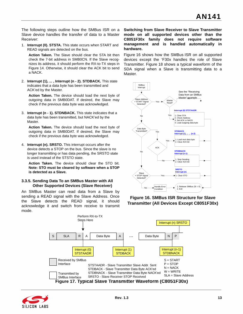
3.3.5. Sending Data To an SMBus Master with All Other Supported Devices (Slave Receiver)
An SMBus Master can read data from a Slave bysending a READ signal with the Slave Address. Oncethe Slave detects the READ signal, it shouldacknowledge it and switch from receive to transmitmode.
Switching from Slave Receiver to Slave Transmittermode on all supported devices other than theC8051F30x family does not require softwaremanagement and is handled automatically inhardware.
Figure 16 shows how the SMBus ISR on all supporteddevices except the ‘F30x handles the role of SlaveTransmitter. Figure 18 shows a typical waveform of theSDA signal when a Slave is transmitting data to aMaster.
STSTAADR - Slave Transmitter Slave Addr. SentSTDBACK - Slave Transmitter Data Byte ACK'edSTDBNACK - Slave Transmitter Data Byte NACK'edSRSTO - Slave Receiver STOP Received
AN141
14 Rev. 1.3
The following steps outline how the SMBus ISR on aSlave device handles the transfer of data to a MasterReceiver:
1. Interrupt (0). STSTAADR. This state occurs when START and READ signals are detected on the bus.
Action Taken. The Slave should clear the STA bit thencheck the 7-bit address in SMB0CN. If the Slave recog-nizes its address, it should set the ACK bit and load theoutgoing data byte into SMB0DAT. Otherwise, it shouldclear the ACK bit to send a NACK.
2. Interrupt (1), ... , Interrupt (n - 2). STDBACK. This state indicates that a data byte has been transmitted.
Action Taken. The device should load the next byte ofoutgoing data in SMB0DAT. If desired, the Slave maycheck if the previous data byte was acknowledged.
3. Interrupt (n - 1). STDNBACK. This state indicates that a data byte has been transmitted, but NACK’ed by the Master.
Action Taken. The device should load the next byte ofoutgoing data in SMB0DAT. If desired, the Slave maycheck if the previous data byte was acknowledged.
4. Interrupt (n). SRSTO. This interrupt occurs after the device detects a STOP on the bus. Since the slave is no longer transmitting or has data pending, the SRSTO state is used instead of the STSTO state.
Action Taken. The device should clear the STO bit.Note: STO must be cleared by software and is notcleared by hardware when a STOP is detected as aSlave.
3.3.6. I2C™ EEPROM Example (Master Transmitter/Receiver)
This example interfaces all supported devices to a 256-byte I2C Serial EEPROM. The SMBus ISR is a modifiedversion of the “SMBus Master Framework” example thatsupports multi-byte transfers. The SMBus ISR behavioris determined by the SMB0CN register and the followingglobal state parameters:
SMB_RW. A boolean flag that indicates an SMBus WRITE if set to ‘0’ and an SMBus READ if set to ‘1’. Note that a random read operation starts as a write and is changed to a read by the ISR after the repeated start is sent.
SMB_SENDWORDADDR. A boolean flag indicating the ISR should send the 8-bit word address after sending the Slave Address+R/W. This flag is cleared by the ISR once the word address has been sent.
SMB_RANDOMREAD. When set to ‘1’, this boolean flag causes the ISR to send a repeated start and switch to read mode after sending the word address.
SMB_ACKPOLL. This flag enables acknowledge polling. When set to ‘1’, the ISR automatically restarts the transfer if the Slave fails to acknowledge its device address.
STSTAADR - Slave Transmitter Slave Addr. SentSTDBACK - Slave Transmitter Data Byte ACK'edSTDBNACK - Slave Transmitter Data Byte NACK'edSRSTO - Slave Receiver STOP Received
AN141
Rev. 1.3 15
The following read and write routines are provided in theexample:
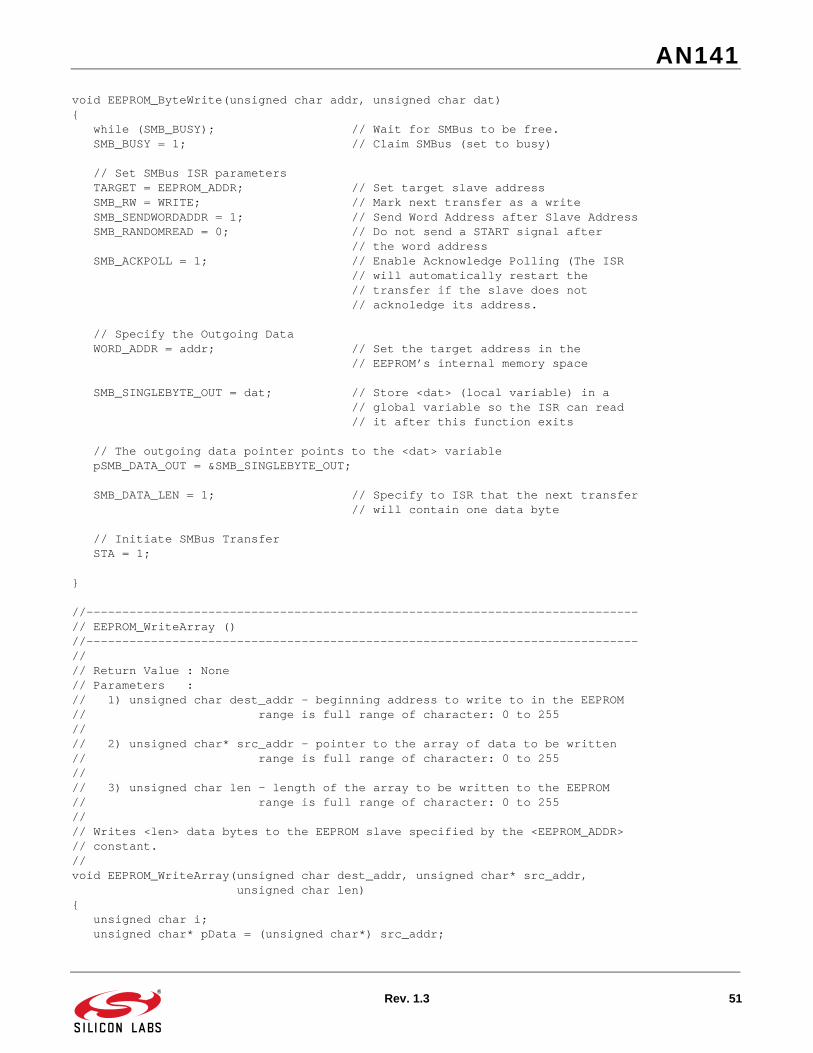
EEPROM_ByteWrite(). The byte write operation writesa single byte to the EEPROM. Figure 19 shows that theoperation consists of a START signal followed by threebytes: the EEPROM’s device address +W (this addresscan be found in the EEPROM data sheet), the 8-bitword address in the EEPROM’s internal memory spacespecifying the memory location to be written, and thedata byte. The write to memory does not take place untilthe STOP signal is transmitted.
Figure 19. EEPROM Byte Write
The EEPROM does not acknowledge its device addresswhile a write to memory is in progress (this behavior isidentical to the Slave inhibit mode on all supporteddevices). This feature can be used as an indicator todetermine when the write operation is complete. Whena new transfer is initiated and the globalSMB_ACKPOLL flag is set, the SMBus ISR willcontinuously poll the EEPROM until it comes “online”.
EEPROM_ByteRead(). This function implements theEEPROM’s random read operation. As Figure 20shows, the host device is in Master Transmitter modeuntil the word address is sent. After the word address isacknowledged, Interrupt (2) sets the STA bit to send arepeated start and changes the SMB_RW flag fromWRITE(0) to READ(1). From this point, the device takesthe role of Master Receiver until the end of the transfer.When the data byte is received, it is NACK’ed to signalthe EEPROM to stop sending. The NACK isimmediately followed by a STOP.
The reason for transmitting a “write” for the first half ofthe transfer is to set the EEPROM’s internal addresspointer. The “read” that takes place in the second half ofthe transfer reads from the data stored at theEEPROM’s internal address pointer.
After each byte is read, the EEPROM’s internal addresspointer is incremented. This allows up to 256 bytes ofdata (the entire EEPROM contents) to be read in asingle transfer.
EEPROM_ReadArray(). This function makes use of themulti-byte transfer capability of the EEPROM. Figure 22shows a typical waveform of an EEPROM multi-byteread.
MTSTA - Master Transmitter START SentMTSLA - Master Transmitter Slave Addr. SentMTDB - Master Transmitter Data Byte SentMRSTA - Master Receiver START SentMRSLA - Master Receiver Slave Addr. SentMTDBFIN - Master Receiver Final Data Byte Received
AN141
16 Rev. 1.3
4. SMBus Debugging Techniques
An SMBus network consists of at least one Master andone Slave. Assuming a minimal network that is notfunctioning properly, either the Master or the Slave maybe causing the failure.
The first step in debugging a minimal SMBus network isisolating the problem to the Master or the Slave. Thisinvolves observing the SCL and SDA traces on anoscilloscope or logic analyzer. As an example, we willdebug a minimal SMBus network with a supporteddevice as the Master and an EEPROM as the Slave.The example code needed to recreate this example isincluded at the end of this note.
In this demonstration, we will be debugging theEEPROM_ReadByte() routine. The goal is to verify theindividual stages (all interrupts and state changes) ofthe transfer shown in Figure 20. We will assume that theEEPROM word we are reading (word address 0x25)contains the data (0xBB). The Slave Address of theEEPROM is 0xA0.
4.1. IDLE stateWhen an SMBus network is idle, both the SCL and theSDA signals are HIGH due to the required pull-upresistors. When the Master issues a START signal, itdrives the SDA then the SCL signal LOW. This startcondition remains on the bus until the Master clears theSI bit or a timeout occurs. In this example, we havedisabled the SCL Low Timeout.
To capture the START signal, we have configured theoscilloscope to trigger on the falling edge of SCL.Program execution is now at the beginning of theEEPROM_ReadByte() routine. We have placed abreakpoint at the top of the SMBus ISR. We now clickthe “go” button in the IDE.
4.2. MTSTA State – Master Transmitter START Signal Sent – Interrupt (0)
Figure 21 shows the bus state as it changes from idle toMTSTA, as seen on the oscilloscope. The Master is alsohalted at the beginning of the SMBus ISR and the SI bithas been set by the SMBus interface. The STARTcondition will remain on the bus until the SMBus ISRclears the SI bit.
Figure 21. Start Signal
Following the waveform in Figure 20, we are now in theMTSTA state. The ISR detects the START condition andprepares the SMBus interface to send the SlaveAddress + WRITE. The Slave address + WRITE will besent after the SI bit is cleared. We now configure theoscilloscope to trigger on the rising edge of SCL andclick the “go” button in the IDE.
MTSTA - Master Transmitter START SentMTSLA - Master Transmitter Slave Addr. SentMTDB - Master Transmitter Data Byte SentMRSTA - Master Receiver START SentMRSLA - Master Receiver Slave Addr. SentMTDB - Master Receiver Data Byte ReceivedMTDBFIN - Master Receiver Final Data Byte Received
AN141
Rev. 1.3 17
4.3. MTSLA State – Master Transmitter Slave Address Sent – Interrupt (1)
Figure 23 shows the bus state as the 7-bit SlaveAddress, the R/W signal, and the ACK signal aretransmitted across the bus.
Figure 23. Slave Address + WRITE
Keep in mind that SDA data is valid on the rising edge ofSCL and stays valid until the next falling edge of SCL.During the first 7 cycles in Figure 23, the Slave Address(0xA0) is transmitted MSB-first from the Master to theSlave. During cycle 7, the Master indicates that thistransfer is a WRITE (1). In the last cycle, the Slavesends an ACK by holding the SDA signal LOW.
The SMBus ISR is now in the MTSLA state. It detectsthat the Slave Address has been ACK’ed and preparesthe SMBus interface to send the first data byte. Sincewe are communicating with an EEPROM, the first databyte is the word address. We now click the “go” buttonin the IDE to advance to the next state.
4.4. MTDB – Master Transmitter Data Byte Sent – Interrupt (2)
Figure 24 shows the EEPROM word address being sentfrom the Master to the Slave.
Figure 24. EEPROM Word Address
The SMBus ISR should now recognize that the 8-bitEEPROM word address (0x25) has been sent andacknowledged by the Slave. It should now set the STAbit to generate a repeated START signal as soon as SIis cleared. While the interrupt is being executed (beforeSI is cleared), SCL is held LOW and the SMBus isstalled. We now click the “go” button in the IDE.
Figure 25 shows SCL being released when SI is clearedthen a repeated start being sent one clock cycle later.
Figure 25. Repeated Start
The SMBus ISR prepares the interface to send theSlave Address + READ. We now click the “go” button inthe IDE.
SCL
SDA1 0 1 0 0 0 0 W A
SCL
SDA1 0 1 0 0 1 0 1 A
SCL
SDA
AN141
18 Rev. 1.3
4.6. MRSLA State – Master Receiver Slave Address Sent – Interrupt (4)
Figure 26 shows the Slave Address (0xA0) + READ (1)being sent from the Master to the Slave. During the lastSCK cycle, the Slave ACK’s the transfer and preparesto drive the bus during the next 8 SCK cycles.
Figure 26. Slave Address + READ
The SMBus interface prepares itself to receive dataduring the next 8 SCK cycles. The transition fromMaster Transmitter to Master Receiver is handledautomatically by hardware. The ISR only needs to clearthe SI bit to advance to the next state. We now click the“go” button in the IDE.
4.7. MRDBFIN State – Master Receiver Final Data Byte Received – Interrupt(5)
Figure 27 shows the data byte (0xBB) being sent fromthe Slave to the Master.
Figure 27. Data Byte
The SMBus ISR reads the data byte from the SMB0DATregister and decides whether to acknowledge it or not.Since we are only reading one byte, the ISR will NACKthis byte to signal the Slave to stop driving the bus. Itwill also set the STA bit to end the transfer. We nowpress the “go” button in the IDE.
SCL
SDA1 0 1 0 0 0 0 R A
SCL
SDA
AN141
Rev. 1.3 19
4.8. Transfer CompleteFigure 28 shows that the Slave stops driving SDA onthe rising edge of the ACK cycle. On that same edge,the Master starts driving SDA HIGH to indicate a NACK.The bus is temporarily driven low after the ACK cycle tofacilitate the generation of the STOP signal. After theSTOP, the bus returns to an idle state.
Figure 28. NACK + STOP
Viewing the signals on the bus at every state changeduring the transfer will help isolate if a problem is due tothe Master or Slave. The waveforms in Figure 8,Figure 11, Figure 13, Figure 17, and Figure 18 can bevery helpful in identifying the number of interrupts andstate changes to expect when examining SMBus trafficon an oscilloscope or logic analyzer.
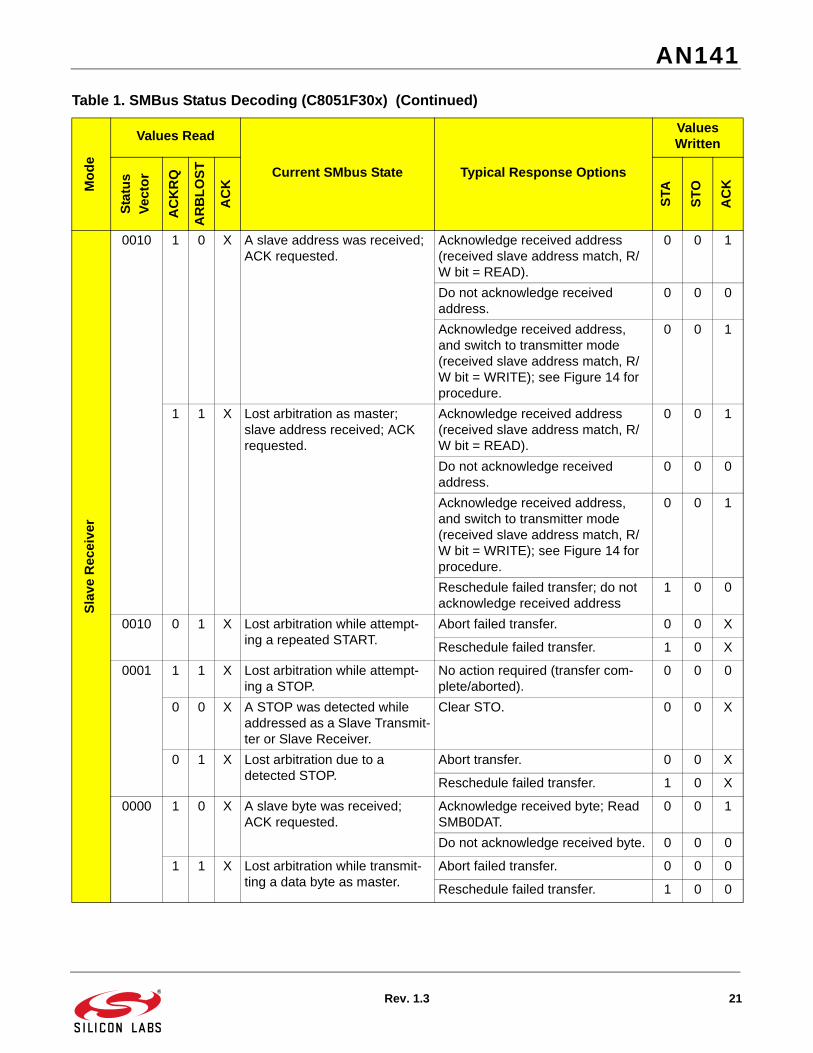
5. SMBus Status Decoding
The current SMBus status can be easily decoded usingthe SMB0CN register. In the table below, STATUSVECTOR refers to the four upper bits of SMB0CN:MASTER, TXMODE, STA, and STO. Note that theshown response options are only the typical responses;application-specific procedures are allowed as long asthey conform with the SMBus specification. Highlightedresponses are allowed but do not conform to the SMBusspecification.
SCL
SDA
AN141
20 Rev. 1.3
Table 1. SMBus Status Decoding (C8051F30x)
Mo
de
Values Read
Current SMbus State Typical Response Options
Values Written
Sta
tus
Ve
cto
r
AC
KR
Q
AR
BL
OS
T
AC
K
STA
ST
O
AC
K
Ma
ster
Tra
ns
mit
ter
1110 0 0 X A master START was gener-ated.
Load slave address + R/W into SMB0DAT.
0 0 X
1100 0 0 0 A master data or address byte was transmitted; NACK received.
Set STA to restart transfer. 1 0 X
Abort transfer. 0 1 X
0 0 1 A master data or address byte was transmitted; ACK received.
Load next data byte into SMB0DAT 0 0 X
End transfer with STOP 0 1 X
End transfer with STOP and start another transfer.
1 1 X
Send repeated START 1 0 X
Switch to Master Receiver Mode (clear SI without writing new data to SMB0DAT).
0 0 X
Ma
ster
Rec
eiv
er
1000 1 0 X A master data byte was received; ACK requested.
Acknowledge received byte; Read SMB0DAT.
0 0 1
Send NACK to indicate last byte, and send STOP.
0 1 0
Send NACK to indicate last byte, and send STOP followed by START.
1 1 0
Send ACK followed by repeated START.
1 0 1
Send NACK to indicate last byte, and send repeated START.
1 0 0
Send ACK and switch to Master Transmitter Mode (write to SMB0DAT before clearing SI).
0 0 1
Send NACK and switch to Master Transmitter Mode (write to SMB0DAT before clearing SI).
0 0 0
Sla
ve T
ran
sm
itte
r
0100 0 0 0 A slave byte was transmitted; NACK received.
No action required (expecting STOP condition).
0 0 X
0 0 1 A slave byte was transmitted; ACK received.
Load SMB0DAT with next data byte to transmit.
0 0 X
0 1 X A Slave byte was transmitted; error detected.
No action required (expecting Mas-ter to end transfer).
0 0 X
0101 0 X X An illegal STOP or bus error was detected while a Slave Transmission was in progress.
Clear STO. 0 0 X
AN141
Rev. 1.3 21
Sla
ve R
ece
ive
r
0010 1 0 X A slave address was received; ACK requested.
Acknowledge received address (received slave address match, R/W bit = READ).
0 0 1
Do not acknowledge received address.
0 0 0
Acknowledge received address, and switch to transmitter mode (received slave address match, R/W bit = WRITE); see Figure 14 for procedure.
0 0 1
1 1 X Lost arbitration as master; slave address received; ACK requested.
Acknowledge received address (received slave address match, R/W bit = READ).
0 0 1
Do not acknowledge received address.
0 0 0
Acknowledge received address, and switch to transmitter mode (received slave address match, R/W bit = WRITE); see Figure 14 for procedure.
0 0 1
Reschedule failed transfer; do not acknowledge received address
1 0 0
0010 0 1 X Lost arbitration while attempt-ing a repeated START.
Abort failed transfer. 0 0 X
Reschedule failed transfer. 1 0 X
0001 1 1 X Lost arbitration while attempt-ing a STOP.
No action required (transfer com-plete/aborted).
0 0 0
0 0 X A STOP was detected while addressed as a Slave Transmit-ter or Slave Receiver.
Clear STO. 0 0 X
0 1 X Lost arbitration due to a detected STOP.
Abort transfer. 0 0 X
Reschedule failed transfer. 1 0 X
0000 1 0 X A slave byte was received; ACK requested.
Acknowledge received byte; Read SMB0DAT.
0 0 1
Do not acknowledge received byte. 0 0 0
1 1 X Lost arbitration while transmit-ting a data byte as master.
Abort failed transfer. 0 0 0
Reschedule failed transfer. 1 0 0
Table 1. SMBus Status Decoding (C8051F30x) (Continued)M
od
e
Values Read
Current SMbus State Typical Response Options
Values Written
Sta
tus
Ve
cto
r
AC
KR
Q
AR
BL
OS
T
AC
K
STA
ST
O
AC
K
AN141
22 Rev. 1.3
Table 2. SMBus Status Decoding (All Supported Devices Except C8051F30x) M
od
e
Values Read
Current SMbus State Typical Response Options
Values Written
Sta
tus
Ve
cto
r
AC
KR
Q
AR
BL
OS
T
AC
K
STA
ST
O
AC
K
Mas
ter
Tra
ns
mit
ter
1110 0 0 X A Master START was gener-ated.
Load Slave Address + R/W into SMB0DAT.
0 0 X
1100 0 0 0 A Master data or address byte was transmitted; NACK received.
Set STA to restart transfer. 1 0 X
Abort transfer. 0 1 X
0 0 1 A Master data or address byte was transmitted; ACK received.
Load next data byte into SMB0DAT. 0 0 X
End transfer with STOP. 0 1 X
End transfer with STOP and start another transfer.
1 1 X
Send repeated START. 1 0 X
Switch to Master Receiver Mode (clear SI without writing new data to SMB0DAT).
0 0 X
Mas
ter
Re
cei
ver
1000 1 0 X A Master data byte was received; ACK requested.
Acknowledge received byte; Read SMB0DAT.
0 0 1
Send NACK to indicate last byte, and send STOP.
0 1 0
Send NACK to indicate last byte, and send STOP followed by START.
1 1 0
Send ACK followed by repeated START.
1 0 1
Send NACK to indicate last byte, and send repeated START.
1 0 0
Send ACK and switch to Master Transmitter Mode (write to SMB0DAT before clearing SI).
0 0 1
Send NACK and switch to Master Transmitter Mode (write to SMB0DAT before clearing SI).
0 0 0
Sla
ve
Tra
nsm
itte
r
0100 0 0 0 A Slave byte was transmitted; NACK received.
No action required (expecting STOP condition).
0 0 X
0 0 1 A Slave byte was transmitted; ACK received.
Load SMB0DAT with next data byte to transmit.
0 0 X
0 1 X A Slave byte was transmitted; error detected.
No action required (expecting Mas-ter to end transfer).
0 0 X
0101 0 X X An illegal STOP or bus error was detected while a Slave Transmission was in progress.
Clear STO. 0 0 X
AN141
Rev. 1.3 23
Sla
ve
Rec
eiv
er
0010 1 0 X A Slave Address was received; ACK requested.
Acknowledge received address. 0 0 1
Do not acknowledge received address.
0 0 0
1 1 X Lost arbitration as Master; Slave Address received; ACK requested.
Acknowledge received address. 0 0 1
Do not acknowledge received address.
0 0 0
Reschedule failed transfer; do not acknowledge received address.
1 0 0
0010 0 1 X Lost arbitration while attempt-ing a repeated START.
Abort failed transfer. 0 0 X
Reschedule failed transfer. 1 0 X
0001 1 1 X Lost arbitration while attempt-ing a STOP.
No action required (transfer complete/aborted).
0 0 0
0 0 X A STOP was detected while addressed as a Slave Transmit-ter or Slave Receiver.
Clear STO. 0 0 X
0 1 X Lost arbitration due to a detected STOP.
Abort transfer. 0 0 X
Reschedule failed transfer. 1 0 X
0000 1 0 X A Slave byte was received; ACK requested.
Acknowledge received byte; Read SMB0DAT.
0 0 1
Do not acknowledge received byte. 0 0 0
1 1 X Lost arbitration while transmit-ting a data byte as Master.
This section contains SMBus Master, Slave, and EEPROM examples for the C8051F33x. Additional examples forthe 'F33x (Master Multibyte, Slave Multibyte, and Multimaster) and examples for other devices are available byrequest. Please contact MCU Tools ([email protected]) or MCU Apps ([email protected]) for moreinformation.
6.1. SMBus Master Framework//-----------------------------------------------------------------------------// F33x_SMBus_Master.c//-----------------------------------------------------------------------------// Copyright 2006 Silicon Laboratories, Inc.// http://www.silabs.com//// Program Description://// Example software to demonstrate the C8051F33x SMBus interface in// Master mode.// - Interrupt-driven SMBus implementation// - Only master states defined (no slave or arbitration)// - 1-byte SMBus data holders used for each transmit and receive// - Timer1 used as SMBus clock source// - Timer3 used by SMBus for SCL low timeout detection// - SCL frequency defined by <SMB_FREQUENCY> constant// - ARBLOST support included// - Pinout:// P0.0 -> SDA (SMBus)// P0.1 -> SCL (SMBus)//// P1.3 -> LED//// P2.0 -> C2D (debug interface)//// all other port pins unused//// How To Test://// 1) Verify that J6 is not populated.// 2) Download code to a ‘F33x device that is connected to a SMBus slave.// 3) Run the code:// a) The test will indicate proper communication with the slave by// toggling the LED on and off each time a value is sent and// received.// b) The best method to view the proper functionality is to run to// the indicated line of code in the TEST CODE section of main and// view the SMB_DATA_IN and SMB_DATA_OUT variables in the Watch// Window.////// FID: 33X000013// Target: C8051F33x// Tool chain: Keil C51 7.50 / Keil EVAL C51// Command Line: None//// Release 1.0// -Initial Revision (TP)// -30 MAR 2006//
//-----------------------------------------------------------------------------// Global CONSTANTS//-----------------------------------------------------------------------------
#define SYSCLK 24500000 // System clock frequency in Hz
#define SMB_FREQUENCY 10000 // Target SCL clock rate // This example supports between 10kHz // and 100kHz
// Device addresses (7 bits, LSB is a don’t care)#define SLAVE_ADDR 0xF0 // Device address for slave target
// Status vector - top 4 bits only#define SMB_MTSTA 0xE0 // (MT) start transmitted#define SMB_MTDB 0xC0 // (MT) data byte transmitted#define SMB_MRDB 0x80 // (MR) data byte received// End status vector definition
//-----------------------------------------------------------------------------// Global VARIABLES//-----------------------------------------------------------------------------unsigned char SMB_DATA_IN; // Global holder for SMBus data // All receive data is written here
unsigned char SMB_DATA_OUT; // Global holder for SMBus data. // All transmit data is read from here
sbit SDA = P0^0; // SMBus on P0.0sbit SCL = P0^1; // and P0.1
AN141
26 Rev. 1.3
//-----------------------------------------------------------------------------// Function PROTOTYPES//-----------------------------------------------------------------------------
//-----------------------------------------------------------------------------// MAIN Routine//-----------------------------------------------------------------------------//// Main routine performs all configuration tasks, then loops forever sending// and receiving SMBus data to the slave <SLAVE_ADDR>.//void main (void){ volatile unsigned char dat; // Test counter unsigned char i; // Dummy variable counters
OSCICN |= 0x03; // Set internal oscillator to highest // setting of 24500000
// If slave is holding SDA low because of an improper SMBus reset or error while(!SDA) { // Provide clock pulses to allow the slave to advance out // of its current state. This will allow it to release SDA. XBR1 = 0x40; // Enable Crossbar SCL = 0; // Drive the clock low for(i = 0; i < 255; i++); // Hold the clock low SCL = 1; // Release the clock while(!SCL); // Wait for open-drain // clock output to rise for(i = 0; i < 10; i++); // Hold the clock high XBR1 = 0x00; // Disable Crossbar }
Port_Init (); // Initialize Crossbar and GPIO
Timer1_Init (); // Configure Timer1 for use as SMBus // clock source
Timer3_Init (); // Configure Timer3 for use with SMBus // low timeout detect
SMBus_Init (); // Configure and enable SMBus
EIE1 |= 0x01; // Enable the SMBus interrupt
AN141
Rev. 1.3 27
LED = 0;
EA = 1; // Global interrupt enable
// TEST CODE-------------------------------------------------------------------
dat = 0; // Output data counter NUM_ERRORS = 0; // Error counter while (1) { // SMBus Write Sequence SMB_DATA_OUT = dat; // Define next outgoing byte TARGET = SLAVE_ADDR; // Target the F3xx/Si8250 Slave for next // SMBus transfer SMB_Write(); // Initiate SMBus write
// SMBus Read Sequence TARGET = SLAVE_ADDR; // Target the F3xx/Si8250 Slave for next // SMBus transfer SMB_Read();
// Check transfer data if(SMB_DATA_IN != SMB_DATA_OUT) // Received data match transmit data? { NUM_ERRORS++; // Increment error counter if no match }
// Indicate that an error has occurred (LED no longer lit) if (NUM_ERRORS > 0) { LED = 0; } else { LED = ~LED; }
// Run to here to view the SMB_DATA_IN and SMB_DATA_OUT variables
dat++;
T0_Wait_ms (1); // Wait 1 ms until the next cycle }
// END TEST CODE---------------------------------------------------------------
//-----------------------------------------------------------------------------// SMBus_Init//-----------------------------------------------------------------------------//// Return Value : None// Parameters : None
AN141
28 Rev. 1.3
//// SMBus configured as follows:// - SMBus enabled// - Slave mode inhibited// - Timer1 used as clock source. The maximum SCL frequency will be// approximately 1/3 the Timer1 overflow rate// - Setup and hold time extensions enabled// - Bus Free and SCL Low timeout detection enabled//void SMBus_Init (void){ SMB0CF = 0x5D; // Use Timer1 overflows as SMBus clock // source; // Disable slave mode; // Enable setup & hold time // extensions; // Enable SMBus Free timeout detect; // Enable SCL low timeout detect;
SMB0CF |= 0x80; // Enable SMBus;}
//-----------------------------------------------------------------------------// Timer1_Init//-----------------------------------------------------------------------------//// Return Value : None// Parameters : None//// Timer1 configured as the SMBus clock source as follows:// - Timer1 in 8-bit auto-reload mode// - SYSCLK or SYSCLK / 4 as Timer1 clock source// - Timer1 overflow rate => 3 * SMB_FREQUENCY// - The resulting SCL clock rate will be ~1/3 the Timer1 overflow rate// - Timer1 enabled//void Timer1_Init (void){
// Make sure the Timer can produce the appropriate frequency in 8-bit mode// Supported SMBus Frequencies range from 10kHz to 100kHz. The CKCON register// settings may need to change for frequencies outside this range.#if ((SYSCLK/SMB_FREQUENCY/3) < 255) #define SCALE 1 CKCON |= 0x08; // Timer1 clock source = SYSCLK#elif ((SYSCLK/SMB_FREQUENCY/4/3) < 255) #define SCALE 4 CKCON |= 0x01; CKCON &= ~0x0A; // Timer1 clock source = SYSCLK / 4#endif
TMOD = 0x20; // Timer1 in 8-bit auto-reload mode
// Timer1 configured to overflow at 1/3 the rate defined by SMB_FREQUENCY TH1 = -(SYSCLK/SMB_FREQUENCY/SCALE/3);
TL1 = TH1; // Init Timer1
TR1 = 1; // Timer1 enabled
AN141
Rev. 1.3 29
}
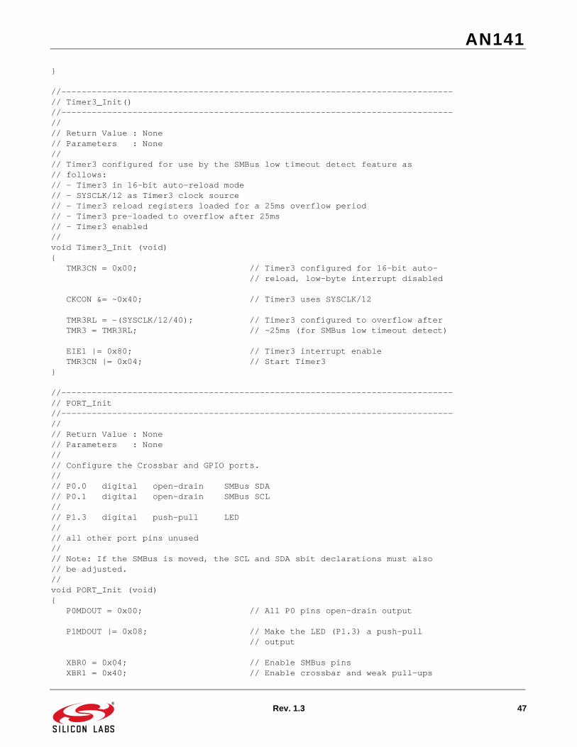
//-----------------------------------------------------------------------------// Timer3_Init//-----------------------------------------------------------------------------//// Return Value : None// Parameters : None//// Timer3 configured for use by the SMBus low timeout detect feature as// follows:// - Timer3 in 16-bit auto-reload mode// - SYSCLK/12 as Timer3 clock source// - Timer3 reload registers loaded for a 25ms overflow period// - Timer3 pre-loaded to overflow after 25ms// - Timer3 enabled//void Timer3_Init (void){ TMR3CN = 0x00; // Timer3 configured for 16-bit auto- // reload, low-byte interrupt disabled
//-----------------------------------------------------------------------------// PORT_Init//-----------------------------------------------------------------------------//// Return Value : None// Parameters : None//// Configure the Crossbar and GPIO ports.//// P0.0 digital open-drain SMBus SDA// P0.1 digital open-drain SMBus SCL//// P1.3 digital push-pull LED//// all other port pins unused//// Note: If the SMBus is moved, the SCL and SDA sbit declarations must also// be adjusted.//void PORT_Init (void){ P0MDOUT = 0x00; // All P0 pins open-drain output
P1MDOUT |= 0x08; // Make the LED (P1.3) a push-pull // output
XBR0 = 0x04; // Enable SMBus pins
AN141
30 Rev. 1.3
XBR1 = 0x40; // Enable crossbar and weak pull-ups
P0 = 0xFF;}
//-----------------------------------------------------------------------------// Interrupt Service Routines//-----------------------------------------------------------------------------
//-----------------------------------------------------------------------------// SMBus Interrupt Service Routine (ISR)//-----------------------------------------------------------------------------//// SMBus ISR state machine// - Master only implementation - no slave or arbitration states defined// - All incoming data is written to global variable <SMB_DATA_IN>// - All outgoing data is read from global variable <SMB_DATA_OUT>//void SMBus_ISR (void) interrupt 7{ bit FAIL = 0; // Used by the ISR to flag failed // transfers static bit ADDR_SEND = 0; // Used by the ISR to flag byte // transmissions as slave addresses
if (ARBLOST == 0) // Check for errors { // Normal operation switch (SMB0CN & 0xF0) // Status vector { // Master Transmitter/Receiver: START condition transmitted. case SMB_MTSTA: SMB0DAT = TARGET; // Load address of the target slave SMB0DAT &= 0xFE; // Clear the LSB of the address for the // R/W bit SMB0DAT |= SMB_RW; // Load R/W bit STA = 0; // Manually clear START bit ADDR_SEND = 1; break;
// Master Transmitter: Data byte transmitted case SMB_MTDB: if (ACK) // Slave ACK? { if (ADDR_SEND) // If the previous byte was a slave { // address, ADDR_SEND = 0; // Next byte is not a slave address if (SMB_RW == WRITE) // If this transfer is a WRITE, { // send data byte SMB0DAT = SMB_DATA_OUT; } else {} // If this transfer is a READ, // proceed with transfer without // writing to SMB0DAT (switch // to receive mode) } else // If previous byte was not a slave { // address,
AN141
Rev. 1.3 31
STO = 1; // Set STO to terminate transfer SMB_BUSY = 0; // And free SMBus interface } } else // If slave NACK, { STO = 1; // Send STOP condition, followed STA = 1; // By a START NUM_ERRORS++; // Indicate error } break;
// Master Receiver: byte received case SMB_MRDB: SMB_DATA_IN = SMB0DAT; // Store received byte SMB_BUSY = 0; // Free SMBus interface ACK = 0; // Send NACK to indicate last byte // of this transfer
STO = 1; // Send STOP to terminate transfer break;
default: FAIL = 1; // Indicate failed transfer // and handle at end of ISR break;
} // end switch } else { // ARBLOST = 1, error occurred... abort transmission FAIL = 1; } // end ARBLOST if
if (FAIL) // If the transfer failed, { SMB0CF &= ~0x80; // Reset communication SMB0CF |= 0x80; STA = 0; STO = 0; ACK = 0;
SMB_BUSY = 0; // Free SMBus
FAIL = 0; LED = 0;
NUM_ERRORS++; // Indicate an error occurred }
SI = 0; // Clear interrupt flag}
//-----------------------------------------------------------------------------// Timer3 Interrupt Service Routine (ISR)//-----------------------------------------------------------------------------//// A Timer3 interrupt indicates an SMBus SCL low timeout.
AN141
32 Rev. 1.3
// The SMBus is disabled and re-enabled here//void Timer3_ISR (void) interrupt 14{ SMB0CF &= ~0x80; // Disable SMBus SMB0CF |= 0x80; // Re-enable SMBus TMR3CN &= ~0x80; // Clear Timer3 interrupt-pending flag STA = 0; SMB_BUSY = 0; // Free SMBus}
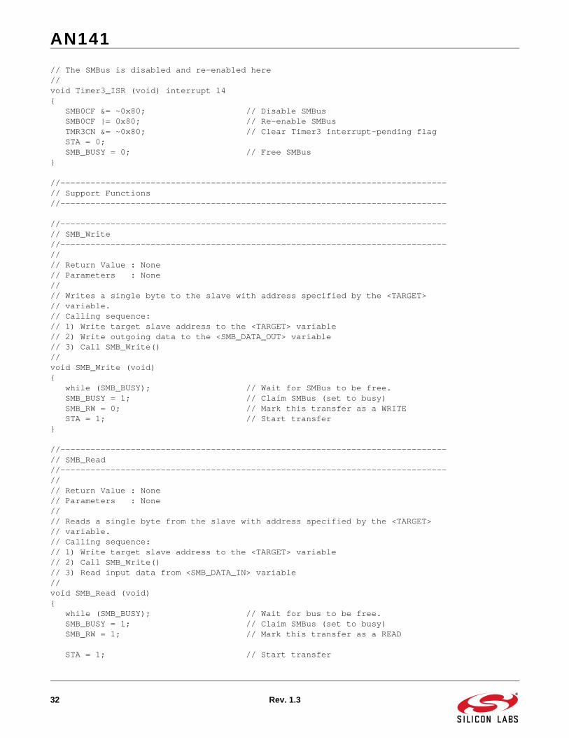
//-----------------------------------------------------------------------------// Support Functions//-----------------------------------------------------------------------------
//-----------------------------------------------------------------------------// SMB_Write//-----------------------------------------------------------------------------//// Return Value : None// Parameters : None//// Writes a single byte to the slave with address specified by the <TARGET>// variable.// Calling sequence:// 1) Write target slave address to the <TARGET> variable// 2) Write outgoing data to the <SMB_DATA_OUT> variable// 3) Call SMB_Write()//void SMB_Write (void){ while (SMB_BUSY); // Wait for SMBus to be free. SMB_BUSY = 1; // Claim SMBus (set to busy) SMB_RW = 0; // Mark this transfer as a WRITE STA = 1; // Start transfer}
//-----------------------------------------------------------------------------// SMB_Read//-----------------------------------------------------------------------------//// Return Value : None// Parameters : None//// Reads a single byte from the slave with address specified by the <TARGET>// variable.// Calling sequence:// 1) Write target slave address to the <TARGET> variable// 2) Call SMB_Write()// 3) Read input data from <SMB_DATA_IN> variable//void SMB_Read (void){ while (SMB_BUSY); // Wait for bus to be free. SMB_BUSY = 1; // Claim SMBus (set to busy) SMB_RW = 1; // Mark this transfer as a READ
STA = 1; // Start transfer
AN141
Rev. 1.3 33
while (SMB_BUSY); // Wait for transfer to complete}
//-----------------------------------------------------------------------------// T0_Wait_ms//-----------------------------------------------------------------------------//// Return Value : None// Parameters :// 1) unsigned char ms - number of milliseconds to wait// range is full range of character: 0 to 255//// Configure Timer0 to wait for <ms> milliseconds using SYSCLK as its time// base.//void T0_Wait_ms (unsigned char ms){ TCON &= ~0x30; // Stop Timer0; Clear TF0 TMOD &= ~0x0f; // 16-bit free run mode TMOD |= 0x01;
CKCON |= 0x04; // Timer0 counts SYSCLKs
while (ms) { TR0 = 0; // Stop Timer0 TH0 = -(SYSCLK/1000 >> 8); // Overflow in 1ms TL0 = -(SYSCLK/1000); TF0 = 0; // Clear overflow indicator TR0 = 1; // Start Timer0 while (!TF0); // Wait for overflow ms--; // Update ms counter }
TR0 = 0; // Stop Timer0}
//-----------------------------------------------------------------------------// End Of File//-----------------------------------------------------------------------------
AN141
34 Rev. 1.3
6.2. SMBus Slave Framework//-----------------------------------------------------------------------------// F33x_SMBus_Slave.c//-----------------------------------------------------------------------------// Copyright 2006 Silicon Laboratories, Inc.// http://www.silabs.com//// Program Description://// Example software to demonstrate the C8051F33x SMBus interface in Slave mode// - Interrupt-driven SMBus implementation// - Only slave states defined// - 1-byte SMBus data holder used for both transmit and receive// - Timer1 used as SMBus clock rate (used only for free timeout detection)// - Timer3 used by SMBus for SCL low timeout detection// - ARBLOST support included// - Pinout:// P0.0 -> SDA (SMBus)// P0.1 -> SCL (SMBus)//// P1.3 -> LED//// P2.0 -> C2D (debug interface)//// all other port pins unused//// How To Test://// 1) Verify that J6 is not populated.// 2) Download code to a ‘F33x device that is connected to a SMBus master.// 3) Run the code. The slave code will write data and read data from the// same data byte, so a successive write and read will effectively echo the// data written. To verify that the code is working properly, verify on the// master that the data written is the same as the data received.//// FID: 33X000010// Target: C8051F33x// Tool chain: Keil C51 7.50 / Keil EVAL C51// Command Line: None//// Release 1.0// -Initial Revision (TP)// -30 MAR 2006//
//-----------------------------------------------------------------------------// Global Constants//-----------------------------------------------------------------------------
#define SYSCLK 24500000 // System clock frequency in Hz
#define SMB_FREQUENCY 10000 // Target SMBus frequency
AN141
Rev. 1.3 35
// This example supports between 10kHz // and 100kHz
#define SLAVE_ADDR 0xF0 // Device addresses (7 bits, // lsb is a don’t care)
// Status vector - top 4 bits only#define SMB_SRADD 0x20 // (SR) slave address received // (also could be a lost // arbitration)#define SMB_SRSTO 0x10 // (SR) STOP detected while SR or ST, // or lost arbitration#define SMB_SRDB 0x00 // (SR) data byte received, or // lost arbitration#define SMB_STDB 0x40 // (ST) data byte transmitted#define SMB_STSTO 0x50 // (ST) STOP detected during a // transaction; bus error// End status vector definition
//-----------------------------------------------------------------------------// Global VARIABLES//-----------------------------------------------------------------------------
unsigned char SMB_DATA; // Global holder for SMBus data. // All receive data is written // here; // all transmit data is read // from here
bit DATA_READY = 0; // Set to ‘1’ by the SMBus ISR // when a new data byte has been // received.
//-----------------------------------------------------------------------------// Function PROTOTYPES//-----------------------------------------------------------------------------
//-----------------------------------------------------------------------------// MAIN Routine//-----------------------------------------------------------------------------//// Main routine performs all configuration tasks, then waits for SMBus
//-----------------------------------------------------------------------------// SMBus_Init()//-----------------------------------------------------------------------------//// Return Value : None// Parameters : None//// SMBus configured as follows:// - SMBus enabled// - Slave mode not inhibited// - Timer1 used as clock source. The maximum SCL frequency will be// approximately 1/3 the Timer1 overflow rate// - Setup and hold time extensions enabled// - Bus Free and SCL Low timeout detection enabled//void SMBus_Init (void){ SMB0CF = 0x1D; // Use Timer1 overflows as SMBus clock // source; // Enable slave mode;
AN141
Rev. 1.3 37
// Enable setup & hold time // extensions; // Enable SMBus Free timeout detect; // Enable SCL low timeout detect;
SMB0CF |= 0x80; // Enable SMBus;}
//-----------------------------------------------------------------------------// Timer1_Init//-----------------------------------------------------------------------------//// Return Value : None// Parameters : None//// Timer1 configured as the SMBus clock source as follows:// - Timer1 in 8-bit auto-reload mode// - SYSCLK or SYSCLK / 4 as Timer1 clock source// - Timer1 overflow rate => 3 * SMB_FREQUENCY// - The resulting SCL clock rate will be ~1/3 the Timer1 overflow rate// - Timer1 enabled//void Timer1_Init (void){
// Make sure the Timer can produce the appropriate frequency in 8-bit mode// Supported SMBus Frequencies range from 10kHz to 100kHz. The CKCON register// settings may need to change for frequencies outside this range.#if ((SYSCLK/SMB_FREQUENCY/3) < 255) #define SCALE 1 CKCON |= 0x08; // Timer1 clock source = SYSCLK#elif ((SYSCLK/SMB_FREQUENCY/4/3) < 255) #define SCALE 4 CKCON |= 0x01; CKCON &= ~0x0A; // Timer1 clock source = SYSCLK / 4#endif
TMOD = 0x20; // Timer1 in 8-bit auto-reload mode
// Timer1 configured to overflow at 1/3 the rate defined by SMB_FREQUENCY TH1 = -(SYSCLK/SMB_FREQUENCY/SCALE/3);
TL1 = TH1; // Init Timer1
TR1 = 1; // Timer1 enabled}
//-----------------------------------------------------------------------------// Timer3_Init//-----------------------------------------------------------------------------//// Return Value : None// Parameters : None//// Timer3 configured for use by the SMBus low timeout detect feature as// follows:// - Timer3 in 16-bit auto-reload mode// - SYSCLK/12 as Timer3 clock source// - Timer3 reload registers loaded for a 25ms overflow period
AN141
38 Rev. 1.3
// - Timer3 pre-loaded to overflow after 25ms// - Timer3 enabled//void Timer3_Init (void){ TMR3CN = 0x00; // Timer3 configured for 16-bit auto- // reload, low-byte interrupt disabled
//-----------------------------------------------------------------------------// PORT_Init//-----------------------------------------------------------------------------//// Return Value : None// Parameters : None//// Configure the Crossbar and GPIO ports.//// P0.0 digital open-drain SMBus SDA// P0.1 digital open-drain SMBus SCL//// P1.3 digital push-pull LED//// all other port pins unused//void PORT_Init (void){ P0MDOUT = 0x00; // All P0 pins open-drain output
P1MDOUT |= 0x08; // Make the LED (P1.3) a push-pull // output
//-----------------------------------------------------------------------------// Interrupt Service Routines//-----------------------------------------------------------------------------
//-----------------------------------------------------------------------------// SMBus Interrupt Service Routine (ISR)//-----------------------------------------------------------------------------//// SMBus ISR state machine// - Slave only implementation - no master states defined// - All incoming data is written to global variable <SMB_DATA_IN>// - All outgoing data is read from global variable <SMB_DATA_OUT>
AN141
Rev. 1.3 39
//void SMBus_ISR (void) interrupt 7{ if (ARBLOST == 0) { switch (SMB0CN & 0xF0) // Decode the SMBus status vector { // Slave Receiver: Start+Address received case SMB_SRADD:
STA = 0; // Clear STA bit if((SMB0DAT&0xFE) == (SLAVE_ADDR&0xFE)) // Decode address { // If the received address matches, ACK = 1; // ACK the received slave address if((SMB0DAT&0x01) == READ) // If the transfer is a master READ, { SMB0DAT = SMB_DATA; // Prepare outgoing byte } } else // If received slave address does not { // match, ACK = 0; // NACK received address } break;
// Slave Receiver: Data received case SMB_SRDB:
SMB_DATA = SMB0DAT; // Store incoming data DATA_READY = 1; // Indicate new data received ACK = 1; // ACK received data
break;
// Slave Receiver: Stop received while either a Slave Receiver or // Slave Transmitter case SMB_SRSTO:
STO = 0; // STO must be cleared by software when // a STOP is detected as a slave break;
// Slave Transmitter: Data byte transmitted case SMB_STDB: // No action required; // one-byte transfers // only for this example break;
// Slave Transmitter: Arbitration lost, Stop detected // // This state will only be entered on a bus error condition. // In normal operation, the slave is no longer sending data or has // data pending when a STOP is received from the master, so the TXMODE // bit is cleared and the slave goes to the SRSTO state. case SMB_STSTO:
STO = 0; // STO must be cleared by software when // a STOP is detected as a slave
AN141
40 Rev. 1.3
break;
// Default: all other cases undefined default:
SMB0CF &= ~0x80; // Reset communication SMB0CF |= 0x80; STA = 0; STO = 0; ACK = 0; break; } } // ARBLOST = 1, Abort failed transfer else { STA = 0; STO = 0; ACK = 0; }
SI = 0; // Clear SMBus interrupt flag}
//-----------------------------------------------------------------------------// Timer3 Interrupt Service Routine (ISR)//-----------------------------------------------------------------------------//// A Timer3 interrupt indicates an SMBus SCL low timeout.// The SMBus is disabled and re-enabled here//void Timer3_ISR (void) interrupt 14{ SMB0CF &= ~0x80; // Disable SMBus SMB0CF |= 0x80; // Re-enable SMBus TMR3CN &= ~0x80; // Clear Timer3 interrupt-pending flag}
//-----------------------------------------------------------------------------// End Of File//-----------------------------------------------------------------------------
AN141
Rev. 1.3 41
6.3. EEPROM Example//-----------------------------------------------------------------------------// F33x_SMBus_EEPROM.c//-----------------------------------------------------------------------------// Copyright 2006 Silicon Laboratories, Inc.// http://www.silabs.com//// Program Description://// This example demonstrates how the C8051F33x SMBus interface can communicate// with a 256 byte I2C Serial EEPROM (Microchip 24LC02B).// - Interrupt-driven SMBus implementation// - Only master states defined (no slave or arbitration)// - Timer1 used as SMBus clock source// - Timer2 used by SMBus for SCL low timeout detection// - SCL frequency defined by <SMB_FREQUENCY> constant// - Pinout:// P0.0 -> SDA (SMBus)// P0.1 -> SCL (SMBus)//// P1.3 -> LED//// P2.0 -> C2D (debug interface)//// all other port pins unused//// How To Test://// 1) Verify that J6 is not populated.// 2) Download code to a ‘F33x device that is connected to a 24LC02B serial// EEPROM (see the EEPROM datasheet for the pinout information).// 3) Run the code:// a) the test will indicate proper communication with the EEPROM by// turning on the LED at the end the end of the test// b) the test can also be verified by running to the if statements// in main and checking the sent and received values by adding// the variables to the Watch Window//// FID: 33X000014// Target: C8051F33x// Tool chain: Keil C51 7.50 / Keil EVAL C51// Command Line: None//// Release 1.0// -Initial Revision (TP)// -30 MAR 2006//
//-----------------------------------------------------------------------------// Includes and Device-Specific Parameters//-----------------------------------------------------------------------------
#include <C8051F330.h>
//-----------------------------------------------------------------------------// Global CONSTANTS//-----------------------------------------------------------------------------
AN141
42 Rev. 1.3
#define SYSCLK 24500000 // System clock frequency in Hz
#define SMB_FREQUENCY 50000 // Target SCL clock rate // This example supports between 10kHz // and 100kHz
// Device addresses (7 bits, lsb is a don’t care)#define EEPROM_ADDR 0xA0 // Device address for slave target // Note: This address is specified // in the Microchip 24LC02B // datasheet.// SMBus Buffer Size#define SMB_BUFF_SIZE 0x08 // Defines the maximum number of bytes // that can be sent or received in a // single transfer
// Status vector - top 4 bits only#define SMB_MTSTA 0xE0 // (MT) start transmitted#define SMB_MTDB 0xC0 // (MT) data byte transmitted#define SMB_MRDB 0x80 // (MR) data byte received// End status vector definition
//-----------------------------------------------------------------------------// Global VARIABLES//-----------------------------------------------------------------------------unsigned char* pSMB_DATA_IN; // Global pointer for SMBus data // All receive data is written here
unsigned char SMB_SINGLEBYTE_OUT; // Global holder for single byte writes.
unsigned char* pSMB_DATA_OUT; // Global pointer for SMBus data. // All transmit data is read from here
unsigned char SMB_DATA_LEN; // Global holder for number of bytes // to send or receive in the current // SMBus transfer.
unsigned char WORD_ADDR; // Global holder for the EEPROM word // address that will be accessed in // the next transfer
bit SMB_BUSY = 0; // Software flag to indicate when the // EEPROM_ByteRead() or // EEPROM_ByteWrite() // functions have claimed the SMBus
bit SMB_RW; // Software flag to indicate the // direction of the current transfer
bit SMB_SENDWORDADDR; // When set, this flag causes the ISR // to send the 8-bit <WORD_ADDR> // after sending the slave address.
AN141
Rev. 1.3 43
bit SMB_RANDOMREAD; // When set, this flag causes the ISR // to send a START signal after sending // the word address. // For the 24LC02B EEPROM, a random read // (a read from a particular address in // memory) starts as a write then // changes to a read after the repeated // start is sent. The ISR handles this // switchover if the <SMB_RANDOMREAD> // bit is set.
bit SMB_ACKPOLL; // When set, this flag causes the ISR // to send a repeated START until the // slave has acknowledged its address
sbit SDA = P0^0; // SMBus on P0.0sbit SCL = P0^1; // and P0.1
//-----------------------------------------------------------------------------// Function PROTOTYPES//-----------------------------------------------------------------------------
//-----------------------------------------------------------------------------// MAIN Routine//-----------------------------------------------------------------------------//// Main routine performs all configuration tasks, then loops forever sending// and receiving SMBus data to the slave EEPROM.
void main (void){ char in_buff[8] = {0}; // Incoming data buffer char out_buff[8] = “ABCDEFG”; // Outgoing data buffer
unsigned char temp_char; // Temporary variable bit error_flag = 0; // Flag for checking EEPROM contents unsigned char i; // Temporary counter variable
// Set internal oscillator to highest // setting of 24500000 (or 12000000 for ‘F320) OSCICN |= 0x03;
// If slave is holding SDA low because of an improper SMBus reset or error while(!SDA) { // Provide clock pulses to allow the slave to advance out // of its current state. This will allow it to release SDA. XBR1 = 0x40; // Enable Crossbar SCL = 0; // Drive the clock low for(i = 0; i < 255; i++); // Hold the clock low SCL = 1; // Release the clock while(!SCL); // Wait for open-drain // clock output to rise for(i = 0; i < 10; i++); // Hold the clock high XBR1 = 0x00; // Disable Crossbar }
Port_Init (); // Initialize Crossbar and GPIO
LED = 0; // Turn off the LED before the test // starts
Timer1_Init (); // Configure Timer1 for use as SMBus // clock source
Timer3_Init (); // Configure Timer3 for use with SMBus // low timeout detect
SMBus_Init (); // Configure and enable SMBus
EIE1 |= 0x01; // Enable the SMBus interrupt
EA = 1; // Global interrupt enable
// Read and write some bytes to the EEPROM and check for proper // communication
// Write the value 0xAA to location 0x25 in the EEPROM EEPROM_ByteWrite(0x25, 0xAA);
// Read the value at location 0x25 in the EEPROM temp_char = EEPROM_ByteRead(0x25);
// Check that the data was read properly if (temp_char != 0xAA) { error_flag = 1; }
AN141
Rev. 1.3 45
// Write the value 0xBB to location 0x25 in the EEPROM EEPROM_ByteWrite(0x25, 0xBB);
// Write the value 0xCC to location 0x38 in the EEPROM EEPROM_ByteWrite(0x38, 0xCC);
// Read the value at location 0x25 in the EEPROM temp_char = EEPROM_ByteRead(0x25);
// Check that the data was read properly if (temp_char != 0xBB) { error_flag = 1; }
// Read the value at location 0x38 in the EEPROM temp_char = EEPROM_ByteRead(0x38);
// Check that the data was read properly if (temp_char != 0xCC) { error_flag = 1; }
// Store the outgoing data buffer at EEPROM address 0x50 EEPROM_WriteArray(0x50, out_buff, sizeof(out_buff));
// Fill the incoming data buffer with data starting at EEPROM address 0x50 EEPROM_ReadArray(in_buff, 0x50, sizeof(in_buff));
// Check that the data that came from the EEPROM is the same as what was // sent for (i = 0; i < sizeof(in_buff); i++) { if (in_buff[i] != out_buff[i]) { error_flag = 1; } }
// Indicate communication is good if (error_flag == 0) { // LED = ON indicates that the test passed LED = 1; }
// Return Value : None// Parameters : None//// The SMBus peripheral is configured as follows:// - SMBus enabled// - Slave mode disabled// - Timer1 used as clock source. The maximum SCL frequency will be// approximately 1/3 the Timer1 overflow rate// - Setup and hold time extensions enabled// - Free and SCL low timeout detection enabled//void SMBus_Init (void){ SMB0CF = 0x5D; // Use Timer1 overflows as SMBus clock // source; // Disable slave mode; // Enable setup & hold time extensions; // Enable SMBus Free timeout detect; // Enable SCL low timeout detect;
SMB0CF |= 0x80; // Enable SMBus;}
//-----------------------------------------------------------------------------// Timer1_Init()//-----------------------------------------------------------------------------//// Return Value : None// Parameters : None//// Timer1 is configured as the SMBus clock source as follows:// - Timer1 in 8-bit auto-reload mode// - SYSCLK / 12 as Timer1 clock source// - Timer1 overflow rate => 3 * SMB_FREQUENCY// - The maximum SCL clock rate will be ~1/3 the Timer1 overflow rate// - Timer1 enabled//void Timer1_Init (void){// Make sure the Timer can produce the appropriate frequency in 8-bit mode// Supported SMBus Frequencies range from 10kHz to 100kHz. The CKCON register// settings may need to change for frequencies outside this range.#if ((SYSCLK/SMB_FREQUENCY/3) < 255) #define SCALE 1 CKCON |= 0x08; // Timer1 clock source = SYSCLK#elif ((SYSCLK/SMB_FREQUENCY/4/3) < 255) #define SCALE 4 CKCON |= 0x01; CKCON &= ~0x0A; // Timer1 clock source = SYSCLK / 4#endif
TMOD = 0x20; // Timer1 in 8-bit auto-reload mode
TH1 = -(SYSCLK/SMB_FREQUENCY/12/3); // Timer1 configured to overflow at 1/3 // the rate defined by SMB_FREQUENCY
TL1 = TH1; // Init Timer1
TR1 = 1; // Timer1 enabled
AN141
Rev. 1.3 47
}
//-----------------------------------------------------------------------------// Timer3_Init()//-----------------------------------------------------------------------------//// Return Value : None// Parameters : None//// Timer3 configured for use by the SMBus low timeout detect feature as// follows:// - Timer3 in 16-bit auto-reload mode// - SYSCLK/12 as Timer3 clock source// - Timer3 reload registers loaded for a 25ms overflow period// - Timer3 pre-loaded to overflow after 25ms// - Timer3 enabled//void Timer3_Init (void){ TMR3CN = 0x00; // Timer3 configured for 16-bit auto- // reload, low-byte interrupt disabled
CKCON &= ~0x40; // Timer3 uses SYSCLK/12
TMR3RL = -(SYSCLK/12/40); // Timer3 configured to overflow after TMR3 = TMR3RL; // ~25ms (for SMBus low timeout detect)
//-----------------------------------------------------------------------------// PORT_Init//-----------------------------------------------------------------------------//// Return Value : None// Parameters : None//// Configure the Crossbar and GPIO ports.//// P0.0 digital open-drain SMBus SDA// P0.1 digital open-drain SMBus SCL//// P1.3 digital push-pull LED//// all other port pins unused//// Note: If the SMBus is moved, the SCL and SDA sbit declarations must also// be adjusted.//void PORT_Init (void){ P0MDOUT = 0x00; // All P0 pins open-drain output
P1MDOUT |= 0x08; // Make the LED (P1.3) a push-pull // output
//-----------------------------------------------------------------------------// SMBus Interrupt Service Routine (ISR)//-----------------------------------------------------------------------------//// SMBus ISR state machine// - Master only implementation - no slave or arbitration states defined// - All incoming data is written starting at the global pointer <pSMB_DATA_IN>// - All outgoing data is read from the global pointer <pSMB_DATA_OUT>//void SMBus_ISR (void) interrupt 7{ bit FAIL = 0; // Used by the ISR to flag failed // transfers
static char i; // Used by the ISR to count the // number of data bytes sent or // received
static bit SEND_START = 0; // Send a start
switch (SMB0CN & 0xF0) // Status vector { // Master Transmitter/Receiver: START condition transmitted. case SMB_MTSTA: SMB0DAT = TARGET; // Load address of the target slave SMB0DAT &= 0xFE; // Clear the LSB of the address for the // R/W bit SMB0DAT |= SMB_RW; // Load R/W bit STA = 0; // Manually clear START bit i = 0; // Reset data byte counter break;
// Master Transmitter: Data byte (or Slave Address) transmitted case SMB_MTDB: if (ACK) // Slave Address or Data Byte { // Acknowledged? if (SEND_START) { STA = 1; SEND_START = 0; break; } if(SMB_SENDWORDADDR) // Are we sending the word address? { SMB_SENDWORDADDR = 0; // Clear flag SMB0DAT = WORD_ADDR; // Send word address
if (SMB_RANDOMREAD) { SEND_START = 1; // Send a START after the next ACK cycle SMB_RW = READ; }
break; }
AN141
Rev. 1.3 49
if (SMB_RW==WRITE) // Is this transfer a WRITE? {
if (i < SMB_DATA_LEN) // Is there data to send? { // send data byte SMB0DAT = *pSMB_DATA_OUT;
// increment data out pointer pSMB_DATA_OUT++;
// increment number of bytes sent i++; } else { STO = 1; // Set STO to terminte transfer SMB_BUSY = 0; // Clear software busy flag } } else {} // If this transfer is a READ, // then take no action. Slave // address was transmitted. A // separate ‘case’ is defined // for data byte recieved. } else // If slave NACK, { if(SMB_ACKPOLL) { STA = 1; // Restart transfer } else { FAIL = 1; // Indicate failed transfer } // and handle at end of ISR } break;
// Master Receiver: byte received case SMB_MRDB: if ( i < SMB_DATA_LEN ) // Is there any data remaining? { *pSMB_DATA_IN = SMB0DAT; // Store received byte pSMB_DATA_IN++; // Increment data in pointer i++; // Increment number of bytes received ACK = 1; // Set ACK bit (may be cleared later // in the code)
}
if (i == SMB_DATA_LEN) // This is the last byte { SMB_BUSY = 0; // Free SMBus interface ACK = 0; // Send NACK to indicate last byte // of this transfer STO = 1; // Send STOP to terminate transfer }
AN141
50 Rev. 1.3
break;
default: FAIL = 1; // Indicate failed transfer // and handle at end of ISR break; }
if (FAIL) // If the transfer failed, { SMB0CF &= ~0x80; // Reset communication SMB0CF |= 0x80; STA = 0; STO = 0; ACK = 0;
SMB_BUSY = 0; // Free SMBus
FAIL = 0; }
SI = 0; // Clear interrupt flag}
//-----------------------------------------------------------------------------// Timer3 Interrupt Service Routine (ISR)//-----------------------------------------------------------------------------//// A Timer3 interrupt indicates an SMBus SCL low timeout.// The SMBus is disabled and re-enabled if a timeout occurs.//void Timer3_ISR (void) interrupt 14{ SMB0CF &= ~0x80; // Disable SMBus SMB0CF |= 0x80; // Re-enable SMBus TMR3CN &= ~0x80; // Clear Timer3 interrupt-pending flag SMB_BUSY = 0; // Free bus}
//-----------------------------------------------------------------------------// Support Functions//-----------------------------------------------------------------------------
//-----------------------------------------------------------------------------// EEPROM_ByteWrite ()//-----------------------------------------------------------------------------//// Return Value : None// Parameters :// 1) unsigned char addr - address to write in the EEPROM// range is full range of character: 0 to 255//// 2) unsigned char dat - data to write to the address <addr> in the EEPROM// range is full range of character: 0 to 255//// This function writes the value in <dat> to location <addr> in the EEPROM// then polls the EEPROM until the write is complete.//
AN141
Rev. 1.3 51
void EEPROM_ByteWrite(unsigned char addr, unsigned char dat){ while (SMB_BUSY); // Wait for SMBus to be free. SMB_BUSY = 1; // Claim SMBus (set to busy)
// Set SMBus ISR parameters TARGET = EEPROM_ADDR; // Set target slave address SMB_RW = WRITE; // Mark next transfer as a write SMB_SENDWORDADDR = 1; // Send Word Address after Slave Address SMB_RANDOMREAD = 0; // Do not send a START signal after // the word address SMB_ACKPOLL = 1; // Enable Acknowledge Polling (The ISR // will automatically restart the // transfer if the slave does not // acknoledge its address.
// Specify the Outgoing Data WORD_ADDR = addr; // Set the target address in the // EEPROM’s internal memory space
SMB_SINGLEBYTE_OUT = dat; // Store <dat> (local variable) in a // global variable so the ISR can read // it after this function exits
// The outgoing data pointer points to the <dat> variable pSMB_DATA_OUT = &SMB_SINGLEBYTE_OUT;
SMB_DATA_LEN = 1; // Specify to ISR that the next transfer // will contain one data byte
// Initiate SMBus Transfer STA = 1;
}
//-----------------------------------------------------------------------------// EEPROM_WriteArray ()//-----------------------------------------------------------------------------//// Return Value : None// Parameters :// 1) unsigned char dest_addr - beginning address to write to in the EEPROM// range is full range of character: 0 to 255//// 2) unsigned char* src_addr - pointer to the array of data to be written// range is full range of character: 0 to 255//// 3) unsigned char len - length of the array to be written to the EEPROM// range is full range of character: 0 to 255//// Writes <len> data bytes to the EEPROM slave specified by the <EEPROM_ADDR>// constant.//void EEPROM_WriteArray(unsigned char dest_addr, unsigned char* src_addr, unsigned char len){ unsigned char i; unsigned char* pData = (unsigned char*) src_addr;
AN141
52 Rev. 1.3
for( i = 0; i < len; i++ ){ EEPROM_ByteWrite(dest_addr++, *pData++); }
}
//-----------------------------------------------------------------------------// EEPROM_ByteRead ()//-----------------------------------------------------------------------------//// Return Value :// 1) unsigned char data - data read from address <addr> in the EEPROM// range is full range of character: 0 to 255//// Parameters :// 1) unsigned char addr - address to read data from the EEPROM// range is full range of character: 0 to 255//// This function returns a single byte from location <addr> in the EEPROM then// polls the <SMB_BUSY> flag until the read is complete.//unsigned char EEPROM_ByteRead(unsigned char addr){ unsigned char retval; // Holds the return value
while (SMB_BUSY); // Wait for SMBus to be free. SMB_BUSY = 1; // Claim SMBus (set to busy)
// Set SMBus ISR parameters TARGET = EEPROM_ADDR; // Set target slave address SMB_RW = WRITE; // A random read starts as a write // then changes to a read after // the repeated start is sent. The // ISR handles this switchover if // the <SMB_RANDOMREAD> bit is set. SMB_SENDWORDADDR = 1; // Send Word Address after Slave Address SMB_RANDOMREAD = 1; // Send a START after the word address SMB_ACKPOLL = 1; // Enable Acknowledge Polling
// Specify the Incoming Data WORD_ADDR = addr; // Set the target address in the // EEPROM’s internal memory space
pSMB_DATA_IN = &retval; // The incoming data pointer points to // the <retval> variable.
SMB_DATA_LEN = 1; // Specify to ISR that the next transfer // will contain one data byte
// Initiate SMBus Transfer STA = 1; while(SMB_BUSY); // Wait until data is read
// EEPROM_ReadArray ()//-----------------------------------------------------------------------------//// Return Value : None// Parameters :// 1) unsigned char* dest_addr - pointer to the array that will be filled// with the data from the EEPROM// range is full range of character: 0 to 255//// 2) unsigned char src_addr - beginning address to read data from the EEPROM// range is full range of character: 0 to 255//// 3) unsigned char len - length of the array to be read from the EEPROM// range is full range of character: 0 to 255//// Reads up to 256 data bytes from the EEPROM slave specified by the// <EEPROM_ADDR> constant.//void EEPROM_ReadArray (unsigned char* dest_addr, unsigned char src_addr, unsigned char len){ while (SMB_BUSY); // Wait for SMBus to be free. SMB_BUSY = 1; // Claim SMBus (set to busy)
// Set SMBus ISR parameters TARGET = EEPROM_ADDR; // Set target slave address SMB_RW = WRITE; // A random read starts as a write // then changes to a read after // the repeated start is sent. The // ISR handles this switchover if // the <SMB_RANDOMREAD> bit is set. SMB_SENDWORDADDR = 1; // Send Word Address after Slave Address SMB_RANDOMREAD = 1; // Send a START after the word address SMB_ACKPOLL = 1; // Enable Acknowledge Polling
// Specify the Incoming Data WORD_ADDR = src_addr; // Set the target address in the // EEPROM’s internal memory space
// Set the the incoming data pointer pSMB_DATA_IN = (unsigned char*) dest_addr;
SMB_DATA_LEN = len; // Specify to ISR that the next transfer // will contain <len> data bytes
// Initiate SMBus Transfer STA = 1; while(SMB_BUSY); // Wait until data is read
}
//-----------------------------------------------------------------------------// End Of File//-----------------------------------------------------------------------------
AN141
54 Rev. 1.3
DOCUMENT CHANGE LIST SECTION:
Revision 1.1 to Revision 1.2 Added support for 'F32x, 'F33x, ‘F34x, 'F35x, and ‘F41x devices.
Fixed various errors in the software examples.
Added arbitration lost handling.
http://www.silabs.com
Silicon Laboratories Inc.400 West Cesar ChavezAustin, TX 78701USA
Simplicity Studio
One-click access to MCU and wireless tools, documentation, software, source code libraries & more. Available for Windows, Mac and Linux!
IoT Portfoliowww.silabs.com/IoT
SW/HWwww.silabs.com/simplicity
Qualitywww.silabs.com/quality
Support and Communitycommunity.silabs.com
DisclaimerSilicon Labs intends to provide customers with the latest, accurate, and in-depth documentation of all peripherals and modules available for system and software implementers using or intending to use the Silicon Labs products. Characterization data, available modules and peripherals, memory sizes and memory addresses refer to each specific device, and "Typical" parameters provided can and do vary in different applications. Application examples described herein are for illustrative purposes only. Silicon Labs reserves the right to make changes without further notice and limitation to product information, specifications, and descriptions herein, and does not give warranties as to the accuracy or completeness of the included information. Silicon Labs shall have no liability for the consequences of use of the information supplied herein. This document does not imply or express copyright licenses granted hereunder to design or fabricate any integrated circuits. The products are not designed or authorized to be used within any Life Support System without the specific written consent of Silicon Labs. A "Life Support System" is any product or system intended to support or sustain life and/or health, which, if it fails, can be reasonably expected to result in significant personal injury or death. Silicon Labs products are not designed or authorized for military applications. Silicon Labs products shall under no circumstances be used in weapons of mass destruction including (but not limited to) nuclear, biological or chemical weapons, or missiles capable of delivering such weapons.
Trademark InformationSilicon Laboratories Inc.® , Silicon Laboratories®, Silicon Labs®, SiLabs® and the Silicon Labs logo®, Bluegiga®, Bluegiga Logo®, Clockbuilder®, CMEMS®, DSPLL®, EFM®, EFM32®, EFR, Ember®, Energy Micro, Energy Micro logo and combinations thereof, "the world’s most energy friendly microcontrollers", Ember®, EZLink®, EZRadio®, EZRadioPRO®, Gecko®, ISOmodem®, Precision32®, ProSLIC®, Simplicity Studio®, SiPHY®, Telegesis, the Telegesis Logo®, USBXpress® and others are trademarks or registered trademarks of Silicon Labs. ARM, CORTEX, Cortex-M3 and THUMB are trademarks or registered trademarks of ARM Holdings. Keil is a registered trademark of ARM Limited. All other products or brand names mentioned herein are trademarks of their respective holders.