SMC-50 Controllers 59 Slow Speed 152Catalog Number Explanation 59 Resistive Loads 154Product Selection— SMC-50 Controller with Internal Bypass 60 Sizing and Selection Tools 160
SMC-3, SMC Flex, and SMC-50 Smart Motor Controllers
OverviewRockwell Automation offers a wide array of starting solutions that range from electromechanical to solid-state. Products that use these methods include across-the-line starters, Smart Motor Controllers (SMC™s), and variable frequency drives.
SMC Controllers
Allen-Bradley SMC controllers are micro-processor based soft starters that are designed to maximize the efficiency of motor starts and stops. SMC controllers are designed to operate 3-phase motors. They feature built-in overload protection and use six silicon-controlled rectifiers (SCRs) (two per phase) to vary the conduction period and control the voltage (and thus, the torque) to the motor during starting, running, and stopping.
Once the motor has been started and is up to speed, full input voltage is applied to the motor. At this point, units with internal bypass power structures bridge the SCRs with their integral bypass contacts, which are rated for AC1 current levels. Bridging the SCR minimizes heat and allows a smaller product for space-conscious applications. In solid-state power structures, the SCRs are always in the circuit switching current. This allows increased robustness for harsher environments (such as shock-type loads) and more aggressive duty cycles.
Allen-Bradley SMCs are ideal for a wide range of applications. The product family consists of three major offerings.
SMC-3
Compact design provides true three-phase control, increased intelligence and unmatched performance. Motor and system diagnostics and an electronic overload with adjustable trip class reduce downtime and protect valuable assets.
• Compact footprint• Easy and secure setup• Integrated bypass• Five start/stop modes
SMC Flex
Modular design features advanced intelligence, performance, and diagnostics; communications flexibility; removable control module, power modules, and fan assembly in a cost-effective package for your demanding production applications.
• Modular for simplified installation and maintenance• Built-in LCD and keypad or personal computer (PC) software setup• Integrated bypass• Nine start/stop modes and three slow-speed modes• Full metering and diagnostics
SMC-50
Designed for customer flexibility – advanced monitoring and protection, superior communications capabilities, and energy saver mode help increase efficiency and reduce downtime.
• Application scalability– Normal and heavy-duty ratings– Expandable I/O and sensor capability– Network integration capabilities
• LCD or personal computer PC software setup• Integrated bypass or solid-state power structures available• External bypass optional• Seventeen start/stop modes and three slow-speed modes
2 Rockwell Automation Publication 150-TD009B-EN-P - March 2019
SMC-3, SMC Flex, and SMC-50 Smart Motor Controllers
Control Mode Overview
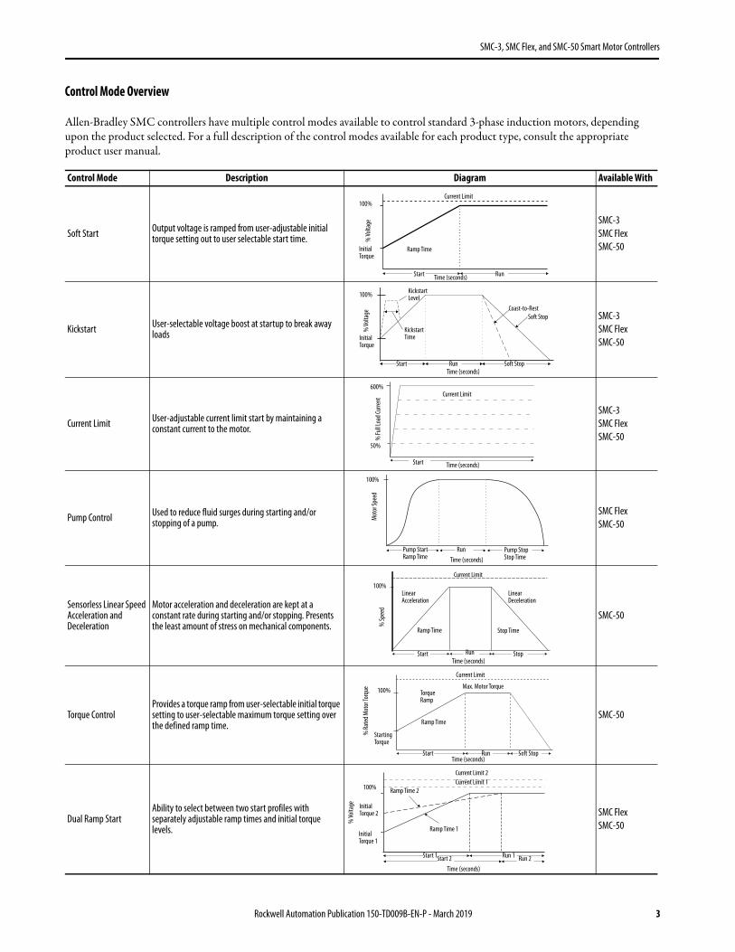
Allen-Bradley SMC controllers have multiple control modes available to control standard 3-phase induction motors, depending upon the product selected. For a full description of the control modes available for each product type, consult the appropriate product user manual.
Control Mode Description Diagram Available With
Soft Start Output voltage is ramped from user-adjustable initial torque setting out to user selectable start time.
SMC-3SMC FlexSMC-50
Kickstart User-selectable voltage boost at startup to break away loads
SMC-3SMC FlexSMC-50
Current Limit User-adjustable current limit start by maintaining a constant current to the motor.
SMC-3SMC FlexSMC-50
Pump Control Used to reduce fluid surges during starting and/or stopping of a pump.
SMC FlexSMC-50
Sensorless Linear Speed Acceleration and Deceleration
Motor acceleration and deceleration are kept at a constant rate during starting and/or stopping. Presents the least amount of stress on mechanical components.
SMC-50
Torque ControlProvides a torque ramp from user-selectable initial torque setting to user-selectable maximum torque setting over the defined ramp time.
SMC-50
Dual Ramp StartAbility to select between two start profiles with separately adjustable ramp times and initial torque levels.
SMC FlexSMC-50
Current Limit
Time (seconds)
Ramp Time
Start Run
% Vo
ltage
Initial Torque
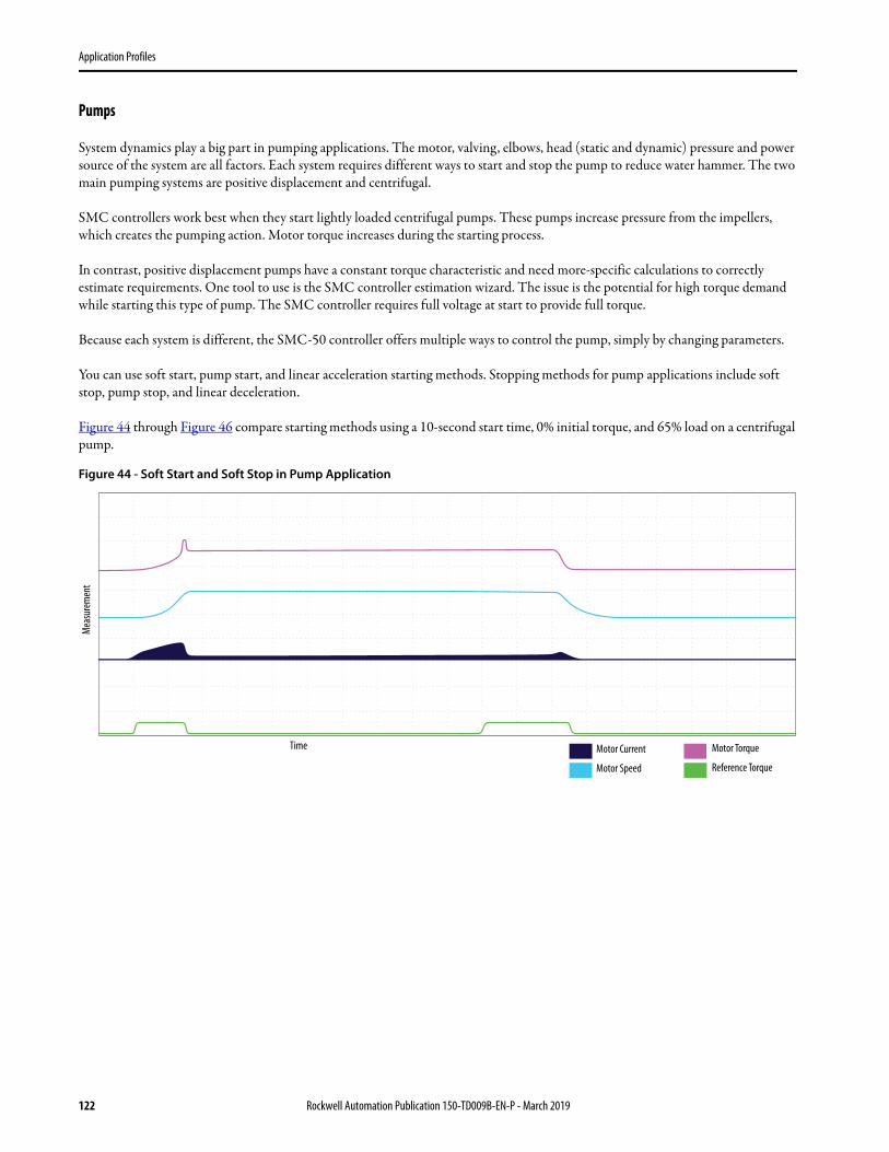
100%
% Vo
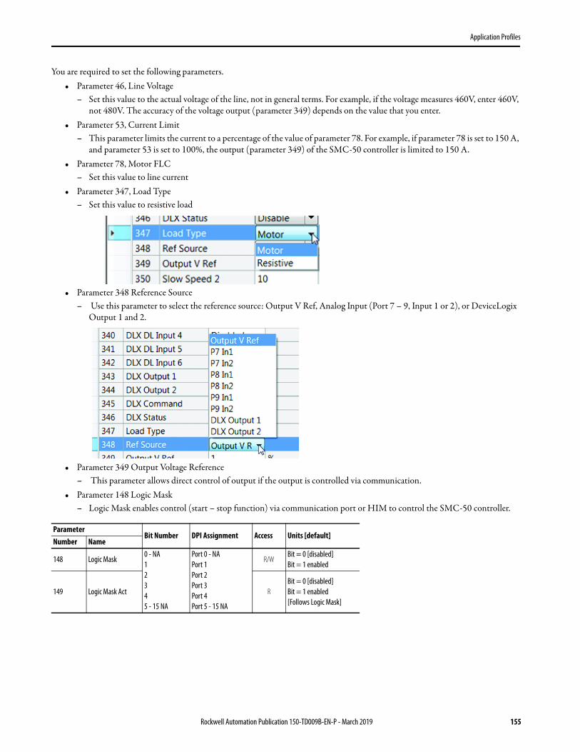
ltage
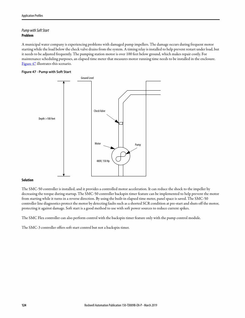
Initial Torque
100%
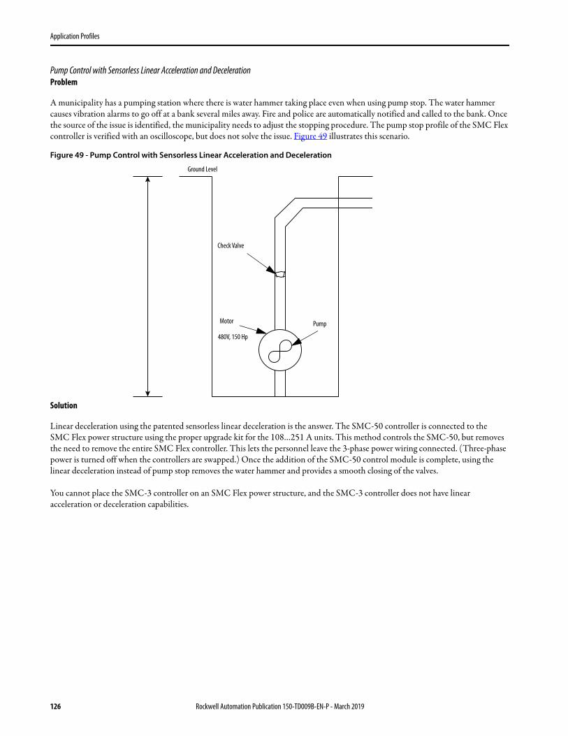
Kickstart Time
Time (seconds)Start Run
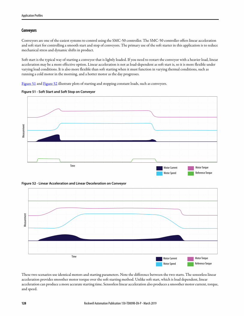
Kickstart Level
Soft Stop
Soft StopCoast-to-Rest
% Fu
ll Loa
d Cur
rent
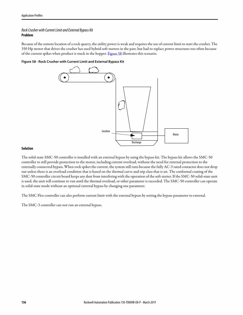
50%
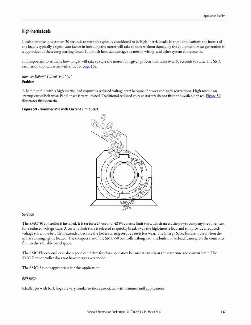
600%Current Limit
Time (seconds)Start
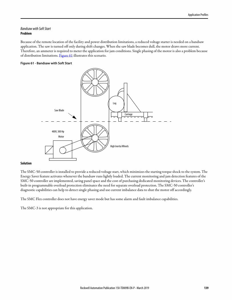
100%
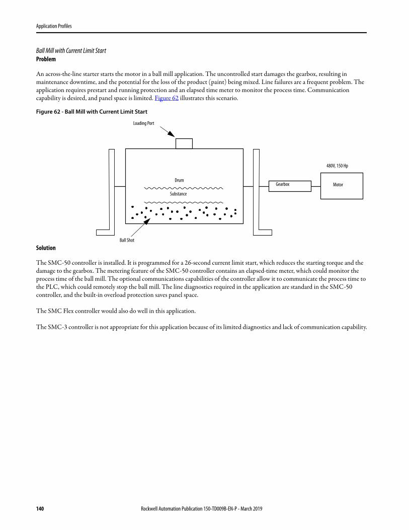
Time (seconds)Run
Mot
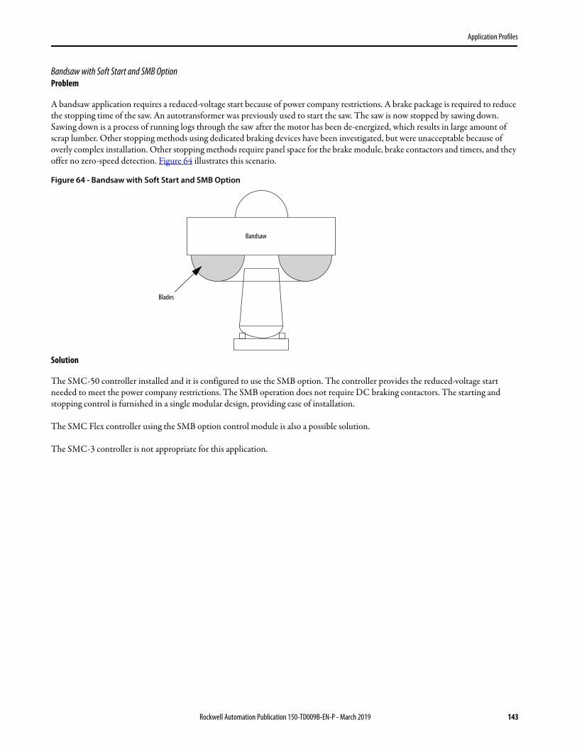
or Sp
eed
Pump Start Ramp Time
Pump Stop Stop Time
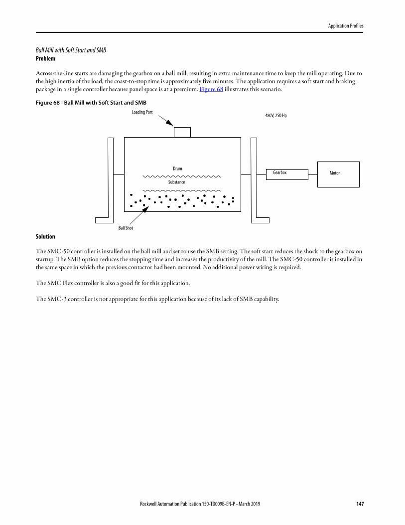
% Sp
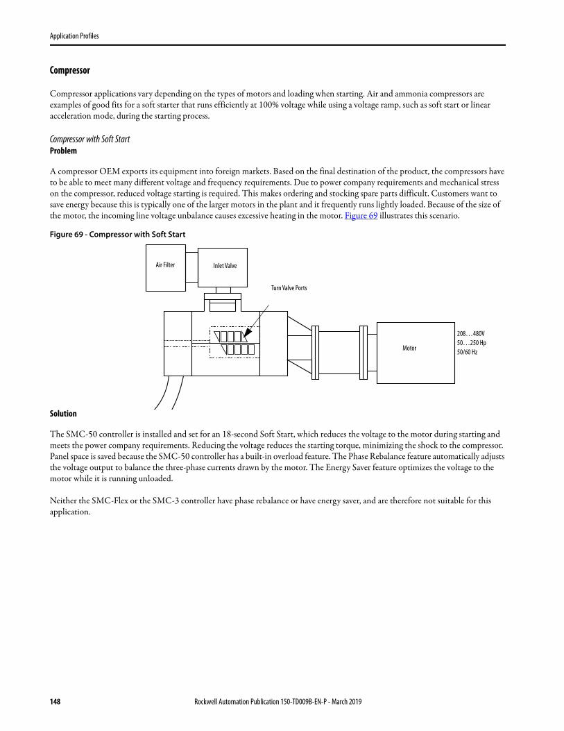
eed
Ramp Time
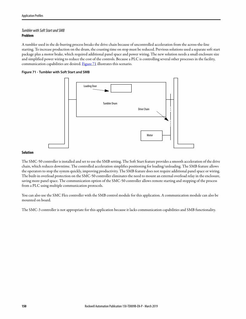
100%
Current Limit
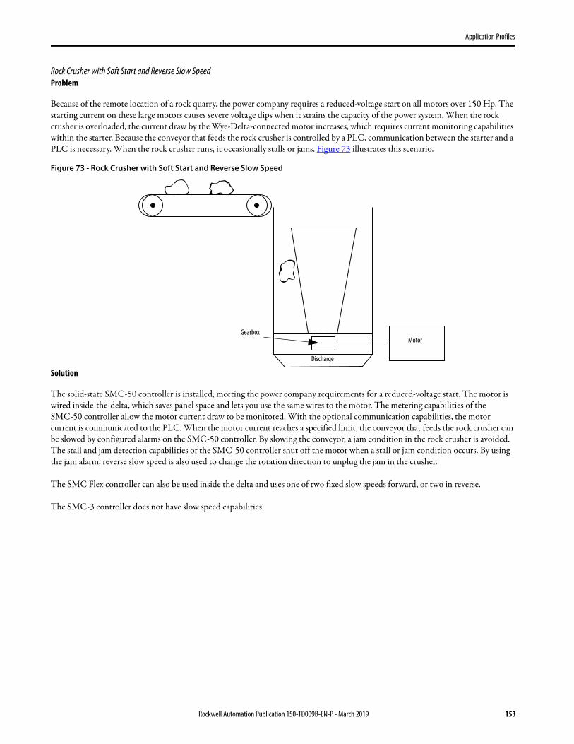
Time (seconds)Start Run Stop
Stop Time
Linear Acceleration
Linear Deceleration
Current Limit
Time (seconds)Start Run Soft Stop
Ramp Time
Torque Ramp
Max. Motor Torque
% Ra
ted M
otor
Torq
ue 100%
Starting Torque
% Vo
ltage
Time (seconds)
Current Limit 2Current Limit 1
100%
Initial Torque 2
Initial Torque 1
Ramp Time 2
Ramp Time 1
Start 1 Run 1Start 2 Run 2
Rockwell Automation Publication 150-TD009B-EN-P - March 2019 3
SMC-3, SMC Flex, and SMC-50 Smart Motor Controllers
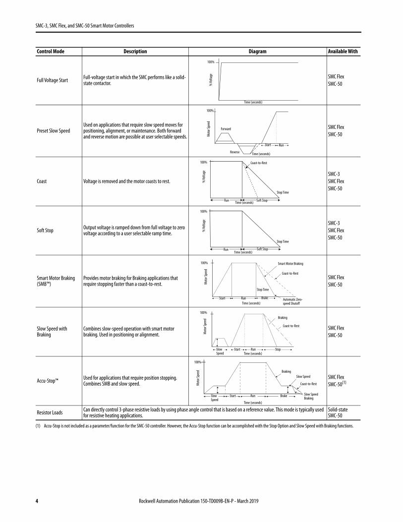
Full Voltage Start Full-voltage start in which the SMC performs like a solid-state contactor.
SMC FlexSMC-50
Preset Slow SpeedUsed on applications that require slow speed moves for positioning, alignment, or maintenance. Both forward and reverse motion are possible at user selectable speeds.
SMC FlexSMC-50
Coast Voltage is removed and the motor coasts to rest.SMC-3SMC FlexSMC-50
Soft Stop Output voltage is ramped down from full voltage to zero voltage according to a user selectable ramp time.
SMC-3SMC FlexSMC-50
Smart Motor Braking (SMB™)
Provides motor braking for Braking applications that require stopping faster than a coast-to-rest.
SMC FlexSMC-50
Slow Speed with Braking
Combines slow-speed operation with smart motor braking. Used in positioning or alignment.
SMC FlexSMC-50
Accu-Stop™ Used for applications that require position stopping. Combines SMB and slow speed.
SMC FlexSMC-50(1)
Resistor Loads Can directly control 3-phase resistive loads by using phase angle control that is based on a reference value. This mode is typically used for resistive heating applications.
Solid-state SMC-50
(1) Accu-Stop is not included as a parameter/function for the SMC-50 controller. However, the Accu-Stop function can be accomplished with the Stop Option and Slow Speed with Braking functions.
Control Mode Description Diagram Available With
Time (seconds)
% Vo
ltage
100%
Mot
or Sp
eed
100%
Time (seconds)
Start Run
Forward
Reverse
% Vo
ltage
100%
Time (seconds)
Stop Time
Run Soft Stop
Coast-to-Rest
% Vo
ltage
100%
Time (seconds)
Stop Time
Run Soft Stop
Mot
or Sp
eed
Automatic Zero-speed Shutoff
100%
Time (seconds)Start Run Brake
Smart Motor Braking
Coast-to-Rest
Stop Time
Mot
or Sp
eed
100%
Time (seconds)Slow Speed
Run
Braking
Coast-to-Rest
StopStart
Mot
or Sp
eed
100%
Time (seconds)
Slow Speed
Run
Braking
Coast-to-Rest
BrakeStart
Slow Speed
Slow Speed Braking
4 Rockwell Automation Publication 150-TD009B-EN-P - March 2019
SMC-3, SMC Flex, and SMC-50 Smart Motor Controllers
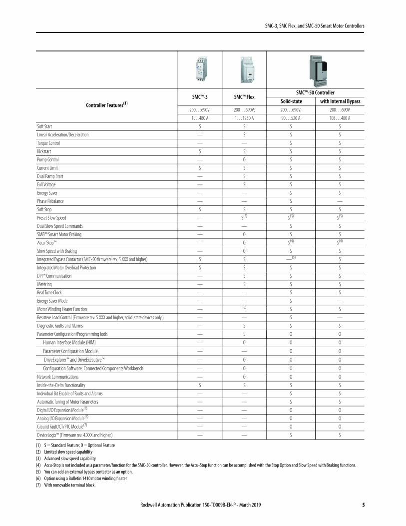
Controller Features(1)
(1) S = Standard Feature; O = Optional Feature
SMC™-3 SMC™ FlexSMC™-50 Controller
Solid-state with Internal Bypass200…690V; 200…690V; 200…690V; 200…690V
1…480 A 1…1250 A 90…520 A 108…480 A
Soft Start S S S S
Linear Acceleration/Deceleration — S S S
Torque Control — — S S
Kickstart S S S S
Pump Control — O S S
Current Limit S S S S
Dual Ramp Start — S S S
Full Voltage — S S S
Energy Saver — — S S
Phase Rebalance — — S —
Soft Stop S S S S
Preset Slow Speed — S(2)
(2) Limited slow speed capability
S(3)
(3) Advanced slow speed capability
S(3)
Dual Slow Speed Commands — — S S
SMB™ Smart Motor Braking — O S S
Accu-Stop™ — O S(4)
(4) Accu-Stop is not included as a parameter/function for the SMC-50 controller. However, the Accu-Stop function can be accomplished with the Stop Option and Slow Speed with Braking functions.
S(4)
Slow Speed with Braking — O S S
Integrated Bypass Contactor (SMC-50 firmware rev. 5.XXX and higher) S S —(5)
(5) You can add an external bypass contactor as an option.
S
Integrated Motor Overload Protection S S S S
DPI™ Communication — S S S
Metering — S S S
Real Time Clock — — S S
Energy Saver Mode — — S —
Motor Winding Heater Function — (6)
(6) Option using a Bulletin 1410 motor winding heater
S S
Resistive Load Control (Firmware rev. 5.XXX and higher, solid-state devices only.) — — S —
Diagnostic Faults and Alarms — S S S
Parameter Configuration/Programming Tools — S O O
Human Interface Module (HIM) — O O O
Parameter Configuration Module — — O O
DriveExplorer™ and DriveExecutive™ — O O O
Configuration Software: Connected Components Workbench — O O O
Network Communications — O O O
Inside-the-Delta Functionality S S S S
Individual Bit Enable of Faults and Alarms — — S S
Automatic Tuning of Motor Parameters — — S S
Digital I/O Expansion Module(7)
(7) With removable terminal block.
— — O O
Analog I/O Expansion Module(7) — — O O
Ground Fault/CT/PTC Module(7) — — O O
DeviceLogix™ (Firmware rev. 4.XXX and higher.) — — S S
Rockwell Automation Publication 150-TD009B-EN-P - March 2019 5
SMC-3, SMC Flex, and SMC-50 Smart Motor Controllers
Notes:
6 Rockwell Automation Publication 150-TD009B-EN-P - March 2019
SMC-3 Controllers
SMC-3 Controllers
The compact design of the SMC-3 controller provides three-phase control, increased intelligence, and unmatched performance in a cost-effective package with overload protection, integrated bypass, and motor system diagnostics. DIP switches and a rotary dial make secure setup easy. This controller features an electronic overload with adjustable trip class.
Modes of operation include the following:
Catalog Number Explanation
Examples that are given in this section are not intended to be used for product selection. Use ProposalWorks to configure the SMC-Flex controller. ProposalWorks is available from http://www.rockwellautomation.com/global/e-tools/overview.page.
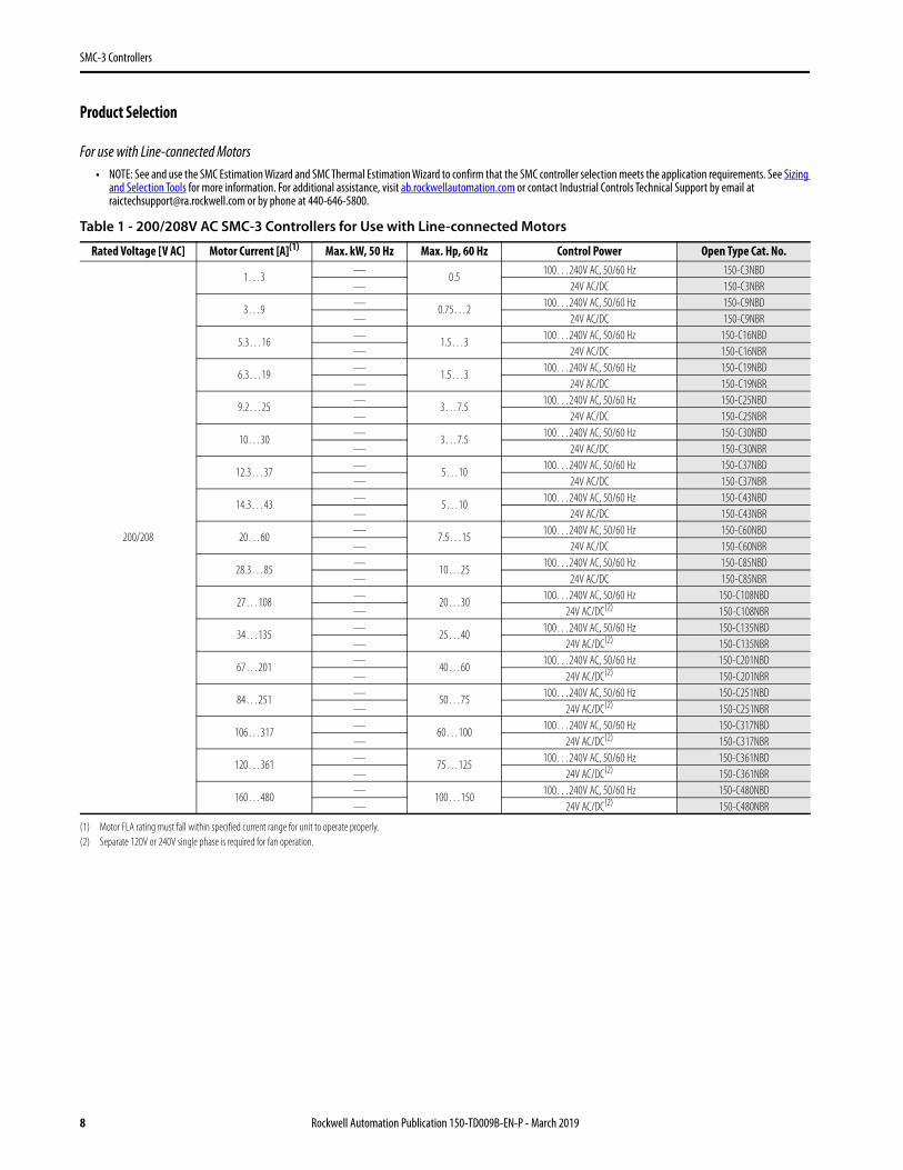
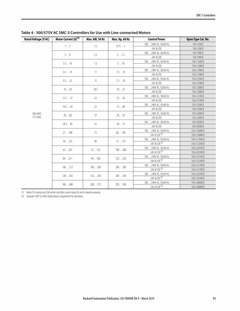
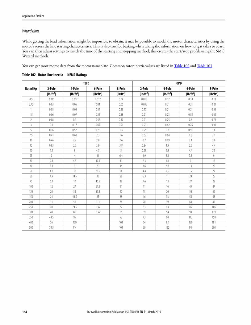
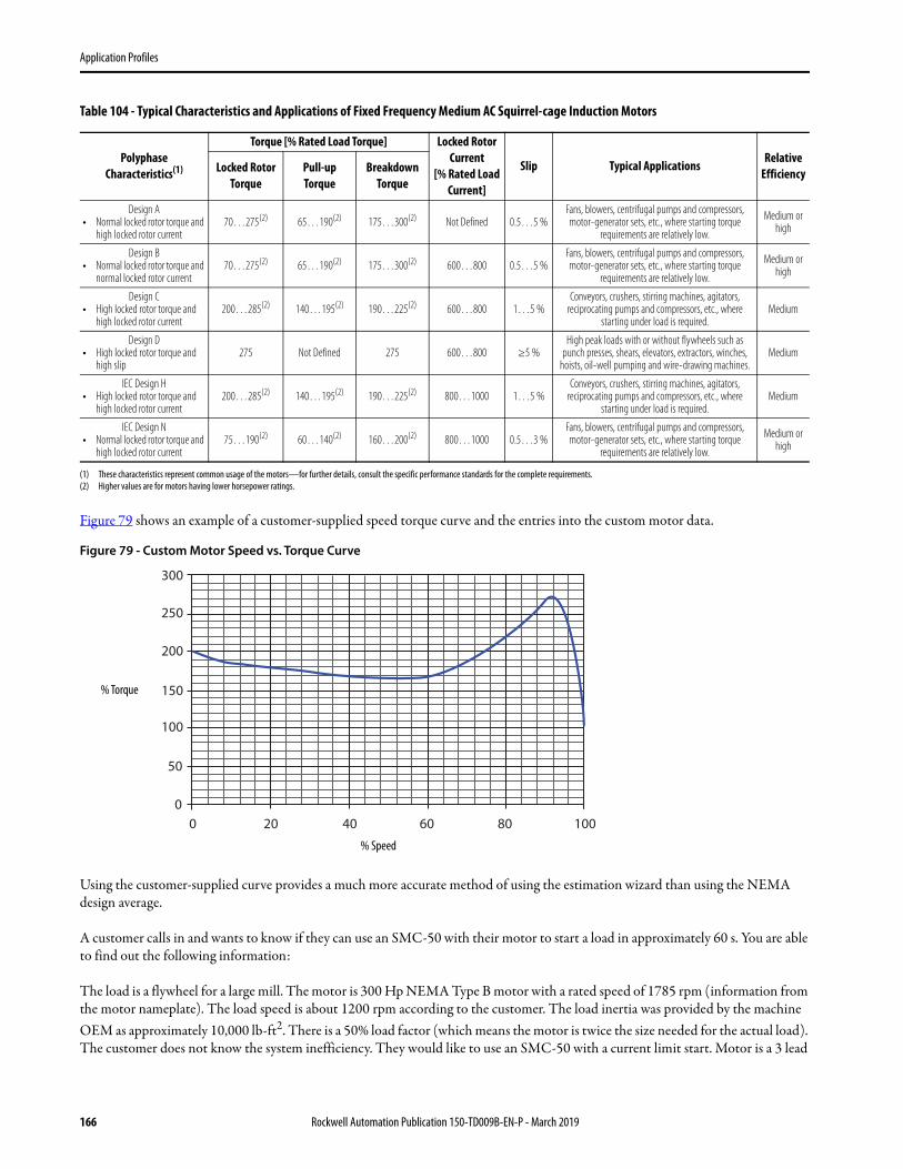
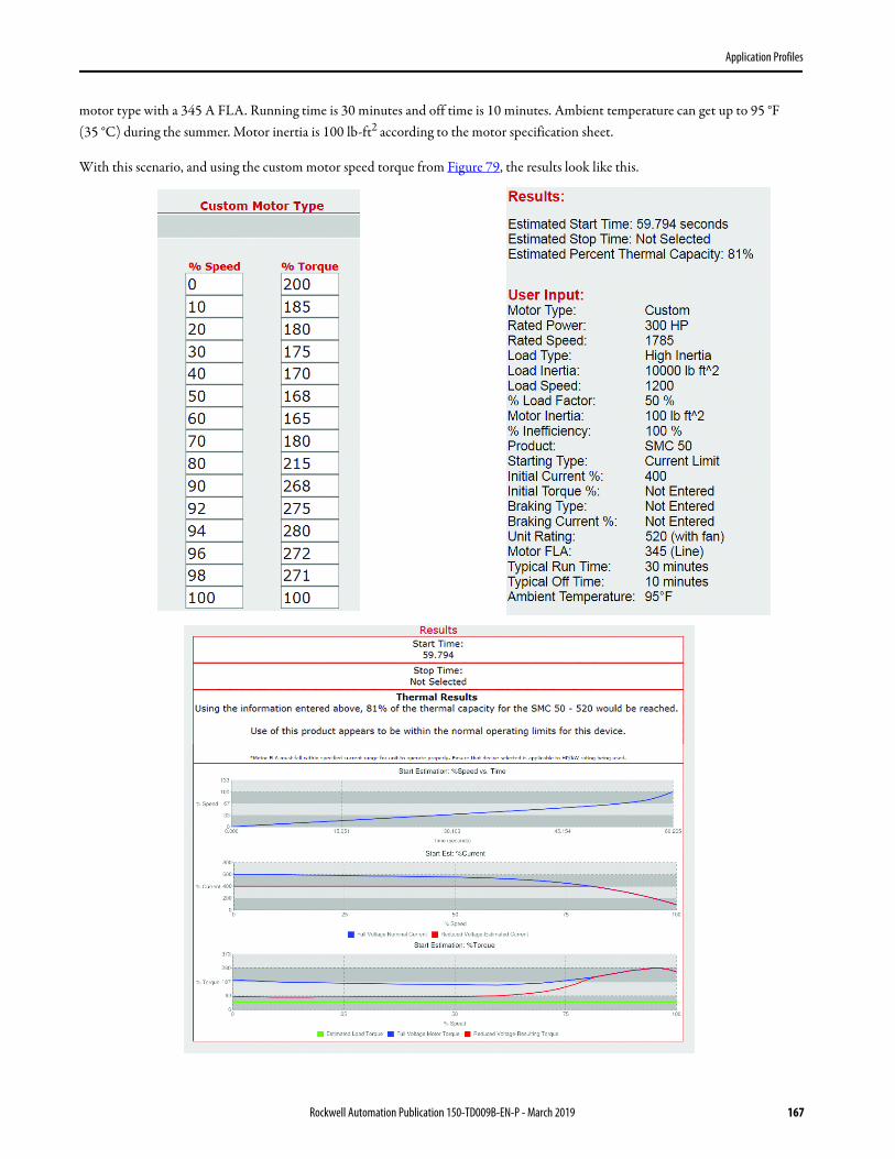
For use with Line-connected Motors• NOTE: See and use the SMC Estimation Wizard and SMC Thermal Estimation Wizard to confirm that the SMC controller selection meets the application requirements. See Sizing
and Selection Tools for more information. For additional assistance, visit ab.rockwellautomation.com or contact Industrial Controls Technical Support by email at [email protected] or by phone at 440-646-5800.
Table 1 - 200/208V AC SMC-3 Controllers for Use with Line-connected Motors
Rated Voltage [V AC] Motor Current [A](1)
(1) Motor FLA rating must fall within specified current range for unit to operate properly.
Max. kW, 50 Hz Max. Hp, 60 Hz Control Power Open Type Cat. No.
200/208
1…3—
0.5100…240V AC, 50/60 Hz 150-C3NBD
— 24V AC/DC 150-C3NBR
3…9—
0.75…2100…240V AC, 50/60 Hz 150-C9NBD
— 24V AC/DC 150-C9NBR
5.3…16—
1.5…3100…240V AC, 50/60 Hz 150-C16NBD
— 24V AC/DC 150-C16NBR
6.3…19—
1.5…3100…240V AC, 50/60 Hz 150-C19NBD
— 24V AC/DC 150-C19NBR
9.2…25—
3…7.5100…240V AC, 50/60 Hz 150-C25NBD
— 24V AC/DC 150-C25NBR
10…30—
3…7.5100…240V AC, 50/60 Hz 150-C30NBD
— 24V AC/DC 150-C30NBR
12.3…37—
5…10100…240V AC, 50/60 Hz 150-C37NBD
— 24V AC/DC 150-C37NBR
14.3…43—
5…10100…240V AC, 50/60 Hz 150-C43NBD
— 24V AC/DC 150-C43NBR
20…60—
7.5…15100…240V AC, 50/60 Hz 150-C60NBD
— 24V AC/DC 150-C60NBR
28.3…85—
10…25100…240V AC, 50/60 Hz 150-C85NBD
— 24V AC/DC 150-C85NBR
27…108—
20…30100…240V AC, 50/60 Hz 150-C108NBD
— 24V AC/DC(2)
(2) Separate 120V or 240V single phase is required for fan operation.
150-C108NBR
34…135—
25…40100…240V AC, 50/60 Hz 150-C135NBD
— 24V AC/DC(2) 150-C135NBR
67…201—
40…60100…240V AC, 50/60 Hz 150-C201NBD
— 24V AC/DC(2) 150-C201NBR
84…251—
50…75100…240V AC, 50/60 Hz 150-C251NBD
— 24V AC/DC(2) 150-C251NBR
106…317—
60…100100…240V AC, 50/60 Hz 150-C317NBD
— 24V AC/DC(2) 150-C317NBR
120…361—
75…125100…240V AC, 50/60 Hz 150-C361NBD
— 24V AC/DC(2) 150-C361NBR
160…480—
100…150100…240V AC, 50/60 Hz 150-C480NBD
— 24V AC/DC(2) 150-C480NBR
8 Rockwell Automation Publication 150-TD009B-EN-P - March 2019
Rockwell Automation Publication 150-TD009B-EN-P - March 2019 11
SMC-3 Controllers
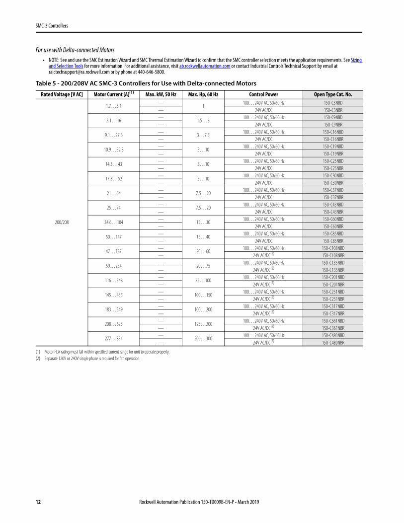
For use with Delta-connected Motors• NOTE: See and use the SMC Estimation Wizard and SMC Thermal Estimation Wizard to confirm that the SMC controller selection meets the application requirements. See Sizing
and Selection Tools for more information. For additional assistance, visit ab.rockwellautomation.com or contact Industrial Controls Technical Support by email at [email protected] or by phone at 440-646-5800.
Table 5 - 200/208V AC SMC-3 Controllers for Use with Delta-connected Motors
Rated Voltage [V AC] Motor Current [A](1)
(1) Motor FLA rating must fall within specified current range for unit to operate properly.
Max. kW, 50 Hz Max. Hp, 60 Hz Control Power Open Type Cat. No.
200/208
1.7…5.1—
1100…240V AC, 50/60 Hz 150-C3NBD
— 24V AC/DC 150-C3NBR
5.1…16—
1.5…3100…240V AC, 50/60 Hz 150-C9NBD
— 24V AC/DC 150-C9NBR
9.1…27.6—
3…7.5100…240V AC, 50/60 Hz 150-C16NBD
— 24V AC/DC 150-C16NBR
10.9…32.8—
3…10100…240V AC, 50/60 Hz 150-C19NBD
— 24V AC/DC 150-C19NBR
14.3…43—
3…10100…240V AC, 50/60 Hz 150-C25NBD
— 24V AC/DC 150-C25NBR
17.3…52—
5…10100…240V AC, 50/60 Hz 150-C30NBD
— 24V AC/DC 150-C30NBR
21…64—
7.5…20100…240V AC, 50/60 Hz 150-C37NBD
— 24V AC/DC 150-C37NBR
25…74—
7.5…20100…240V AC, 50/60 Hz 150-C43NBD
— 24V AC/DC 150-C43NBR
34.6…104—
15…30100…240V AC, 50/60 Hz 150-C60NBD
— 24V AC/DC 150-C60NBR
50…147—
15…40100…240V AC, 50/60 Hz 150-C85NBD
— 24V AC/DC 150-C85NBR
47…187—
20…60100…240V AC, 50/60 Hz 150-C108NBD
— 24V AC/DC(2)
(2) Separate 120V or 240V single phase is required for fan operation.
150-C108NBR
59…234—
20…75100…240V AC, 50/60 Hz 150-C135NBD
— 24V AC/DC(2) 150-C135NBR
116…348—
75…100100…240V AC, 50/60 Hz 150-C201NBD
— 24V AC/DC(2) 150-C201NBR
145…435—
100…150100…240V AC, 50/60 Hz 150-C251NBD
— 24V AC/DC(2) 150-C251NBR
183…549—
100…200100…240V AC, 50/60 Hz 150-C317NBD
— 24V AC/DC(2) 150-C317NBR
208…625—
125…200100…240V AC, 50/60 Hz 150-C361NBD
— 24V AC/DC(2) 150-C361NBR
277…831—
200…300100…240V AC, 50/60 Hz 150-C480NBD
— 24V AC/DC(2) 150-C480NBR
12 Rockwell Automation Publication 150-TD009B-EN-P - March 2019
Rockwell Automation Publication 150-TD009B-EN-P - March 2019 15
SMC-3 Controllers
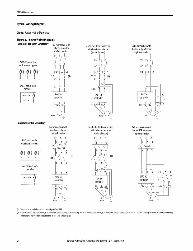
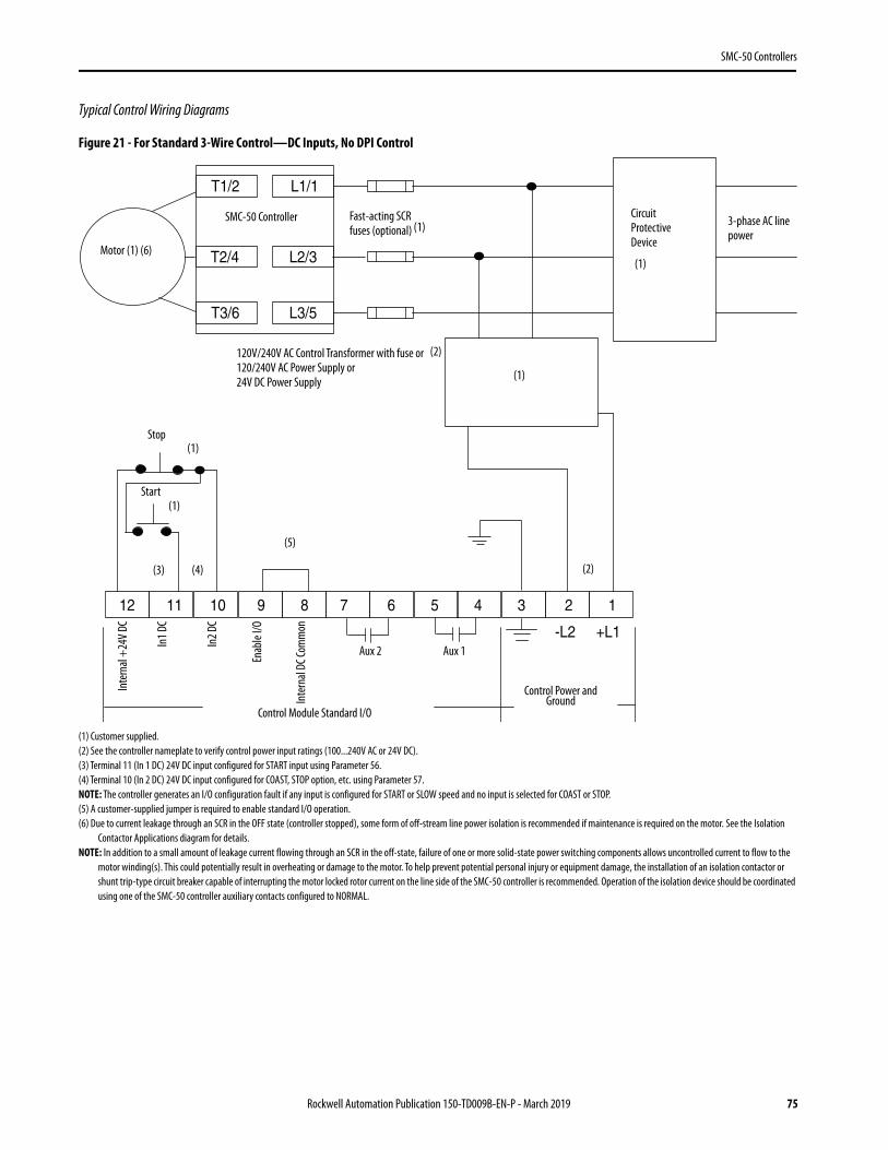
Typical Wiring Diagrams
Figure 1 - Two-wire Configuration
(1) Customer supplied.
Figure 2 - Three-wire Configuration
(1) Customer supplied.
SMC-3 Control Terminals
E-Stop
H4H2
H1H3
X1 X2
Trans.
Ground
A2A1 IN1 IN2
OVLD/Fault AUX #1
97 98 13 14
-TC
-SB
Two-WireDevice
SMC-3(PowerConnections)
IEC
SMC-3 (Power Connections)
SMC-3 Control Terminals
L3/5
T1/2L1/1
T2/4
T3/6
L2/3
H4H2
H1H3
X1 X2
Trans. GroundE-Stop
Two-wire
Device
NEMA
(1)
(1)
SMC-3controller
SMC-3controller
IEC NEMA
SMC-3 Control Terminals
E-Stop
H4H2
H1H3
X1 X2
Trans.
Ground
A2A1 IN1 IN2
OVLD/Fault AUX #1
97 98 13 14
-TC
-SB1
SMC-3(PowerConnections)
Stop Option-SB2
Start-SB3
(1)
(1)
SMC-3controller
SMC-3controller
16 Rockwell Automation Publication 150-TD009B-EN-P - March 2019
SMC-3 Controllers
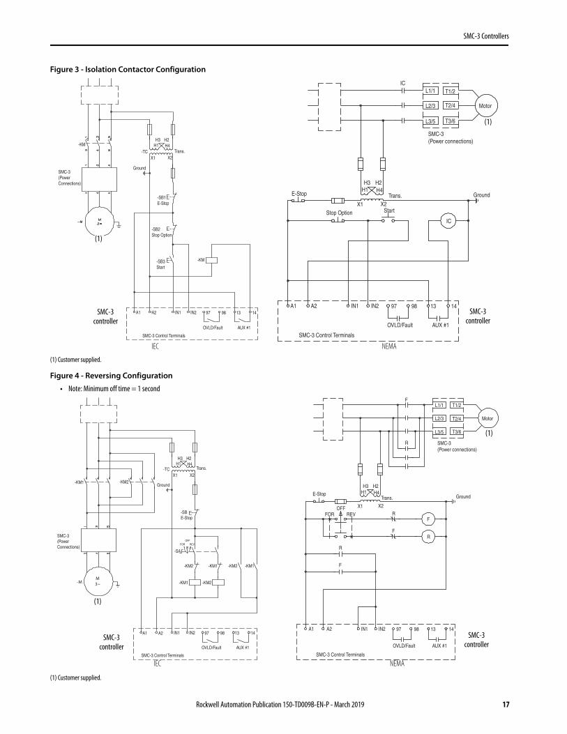
Figure 3 - Isolation Contactor Configuration
(1) Customer supplied.
Figure 4 - Reversing Configuration
• Note: Minimum off time = 1 second
(1) Customer supplied.
IEC NEMASMC-3 Control Terminals
H4H2
H1H3
X1 X2Trans.
Ground
A2A1 IN1 IN2
OVLD/Fault AUX #1
97 98 13 14
-TC
-SB1E-Stop
-KM
SMC-3(PowerConnections)
-SB3Start
-SB2Stop Option
-KM
Motor
L3/5
T1/2L1/1
T2/4
T3/6
L2/3
SMC-3(Power connections)
SMC-3 Control Terminals
E-StopH4H2
H1H3
X1 X2Trans. Ground
A2A1 IN1 IN2
OVLD/Fault AUX #1
97 98 13 14
IC
ICStop Option Start
(1)
(1)
SMC-3controller
SMC-3controller
IEC NEMASMC-3 Control Terminals
H4H2
H1H3
X1 X2
Trans.
Ground
A2A1 IN1 IN2
OVLD/Fault AUX #1
97 98 13 14
SMC-3(PowerConnections)
-TC
-KM2-KM1
-SBE-Stop
-KM2-KM1
-KM2 -KM1 -KM2 -KM1
-SA
FOR REVOFF
M
3~-M
Motor
L3/5
T1/2L1/1
T2/4
T3/6
L2/3
SMC-3(Power connections)
SMC-3 Control Terminals
E-Stop H4H2
H1H3
X1 X2
Trans. Ground
A2A1 IN1 IN2
OVLD/Fault AUX #1
97 98 13 14
F
FR
R
F
R
FOR REVOFF
F
R
(1)
(1)
SMC-3controller
SMC-3controller
Rockwell Automation Publication 150-TD009B-EN-P - March 2019 17
SMC-3 Controllers
Accessories
Auxiliary Contact Blocks
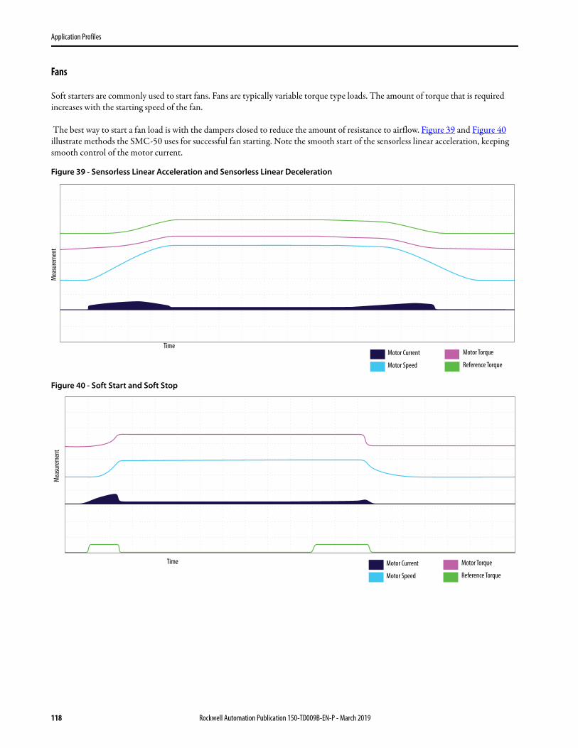
Fans
Connecting Modules
Protective Modules
Do not place protective modules on the load side of a device when using an inside-the-delta connection.
IEC Line- or Load-side Terminal Covers
Description N.O. N.C. Connection Diagram Cat. No.
Auxiliary Contact Blocks for side mounting with sequence terminal designations• 1- and 2-pole• Quick and easy mounting without tools • One block per device only
1 0 150-CA10
2 0 150-CA20
0 1 150-CA01
1 1 150-CA11 (Form C)
Description For Use With Pkg. Qty. Cat. No.
Fan• Field installed
Optional 150-C3…37
1
150-CF64
Replacement
150-C43…85 150-CF147
150-C108, 150-C135 41391-801-03
150-C201, 150-C251 41391-801-01
150-C317…C480 41391-801-02
Description For Use With Pkg. Qty. Cat. No.
Connecting modules to 140-M• Electrical interconnection between SMC-3 and 140-M. • Motor protector and SMC-3 must be mounted separately.
Connects 140-M-C to 150-C3…25 1 150-CC25
Connects 140-M-D to 150-C3…25 1 150-CD25
Connects 140-M-F to 150-C3…37 1 150-CF45
Connecting modules to 100-C• Electrical interconnection between SMC-3 and 100-C. • Contactor and SMC-3 must be mounted separately.
Connects 100-C09…23 to 150-C3…19 1 150-CI23
Connects 100-C30…37 to 150-C3…37 1 150-CI37
Description For Use With Pkg. Qty. Cat. No.
480V Protective Module
150-C3…37NB 1 150-C84
150-C43…85NB 1 150-C84P
150-C108…480NB (line and/or load) 1 150-F84L
600V Protective Module
150-C3…37NC 1 150-C86
150-C43…85NC (line and/or load) 1 150-C86P
150-C108…480NC (line and/or load) 1 150-F86L
Description(1) (2)
(1) 3…85 A units have terminal covers as standard. No additional terminal guards are required.(2) SMC-3 controllers that are rated from 108…480 A are shipped with one terminal cover as standard.
Current Range [A] Pkg. Qty. Cat. No.
• Dead front protection• IP2X finger safe when used with 250 MCM cable
108…135 1 150-TC1
201…251 1 150-TC2
• Dead front protection• IP2X finger safe when used with 500 MCM cable 317…480 1 150-TC3
18 Rockwell Automation Publication 150-TD009B-EN-P - March 2019
SMC-3 Controllers
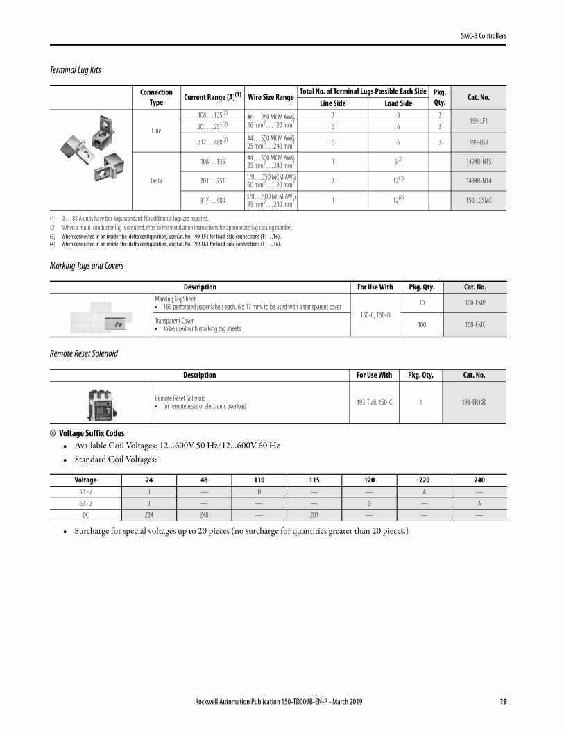
Terminal Lug Kits
Marking Tags and Covers
Remote Reset Solenoid
Voltage Suffix Codes• Available Coil Voltages: 12…600V 50 Hz/12…600V 60 Hz• Standard Coil Voltages:
• Surcharge for special voltages up to 20 pieces (no surcharge for quantities greater than 20 pieces.)
Connection Type
Current Range [A](1)
(1) 3…85 A units have box lugs standard. No additional lugs are required.
Wire Size RangeTotal No. of Terminal Lugs Possible Each Side Pkg.
Qty.Cat. No.
Line Side Load Side
Line
108…135(2)
(2) When a multi-conductor lug is required, refer to the installation instructions for appropriate lug catalog number.
EN/IEC 60947-1 CE Marked (Open Type) per EMC and Low Voltage Directive
EN/IEC 60947-4-2 CCC Certified
20 Rockwell Automation Publication 150-TD009B-EN-P - March 2019
SMC-3 Controllers
Table 12 - Short-circuit Protection Ratings
Attribute Description
SCPD PerformanceType 1(1)
(1) Type 1 performance/protection indicates that, under a short-circuit condition, the fused or circuit breaker-protected starter shall cause no danger to persons or installation but may not be suitable for further service without repair or replacement.
Non-Time Delay Thermal Magnetic Circuit Breaker
SCPD List(2)
(2) Consult local codes for proper sizing of short-circuit protection.
Max. Standard Available Fault Max. Standard Fuse [A](3)
(3) Non-time delay fuses (K5).
Max. Standard Available Fault Max. Circuit Breaker [A]
Line Device Operational Current Rating [A]
3 5 kA 12 5 kA 15
9 5 kA 30 5 kA 30
16 5 kA 60 5 kA 60
19 5 kA 70 5 kA 70
25 5 kA 100 5 kA 100
30 10 kA 110 10 kA 110
37 10 kA 125 10 kA 125
43 10 kA 150 10 kA 150
60 10 kA 225 10 kA 225
85 10 kA 300 10 kA 300
108 10 kA 400 10 kA 300
135 10 kA 500 10 kA 400
201 18 kA 600 18 kA 600
251 18 kA 700 18 kA 700
317 30 kA 800 30 kA 800
361 30 kA 1000 30 kA 1000
480 42 kA 1200 42 kA 1200
Delta Device Operational Current Rating [A]
5.1 5 kA 15 5 kA 15
16 5 kA 60 5 kA 60
27.6 5 kA 70 5 kA 70
32.8 5 kA 125 5 kA 125
43 5 kA 150 5 kA 150
52 10 kA 200 10 kA 200
64 10 kA 250 10 kA 250
74 10 kA 250 10 kA 250
104 10 kA 400 10 kA 300
147 10 kA 400 10 kA 400
187 10 kA 600 10 kA 500
234 10 kA 700 10 kA 700
348 18 kA 1000 18 kA 1000
435 18 kA 1200 18 kA 1200
549 30 kA 1600 30 kA 1600
625 30 kA 1600 30 kA 1600
831 42 kA 1600 30 kA 1600
831 42 kA 1600 42 kA 1200
Rockwell Automation Publication 150-TD009B-EN-P - March 2019 21
SMC-3 Controllers
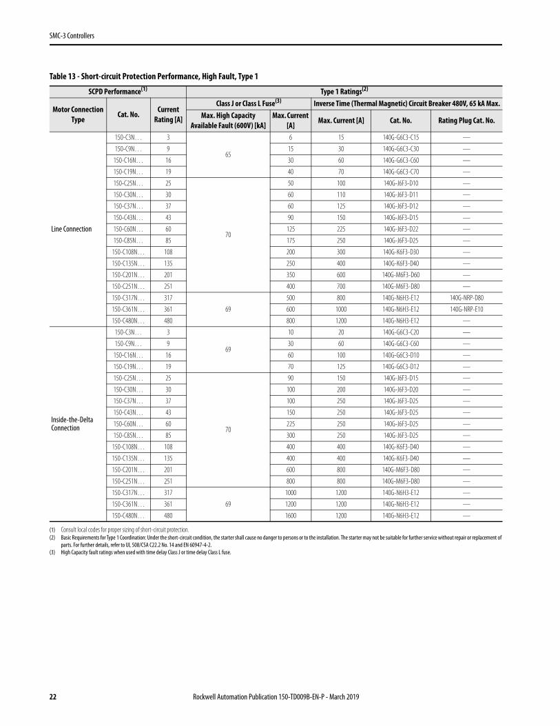
Table 13 - Short-circuit Protection Performance, High Fault, Type 1
SCPD Performance(1)
(1) Consult local codes for proper sizing of short-circuit protection.
Type 1 Ratings(2)
(2) Basic Requirements for Type 1 Coordination: Under the short-circuit condition, the starter shall cause no danger to persons or to the installation. The starter may not be suitable for further service without repair or replacement of parts. For further details, refer to UL 508/CSA C22.2 No. 14 and EN 60947-4-2.
Motor Connection Type
Cat. No.Current
Rating [A]
Class J or Class L Fuse(3)
(3) High Capacity fault ratings when used with time delay Class J or time delay Class L fuse.
Inverse Time (Thermal Magnetic) Circuit Breaker 480V, 65 kA Max.Max. High Capacity
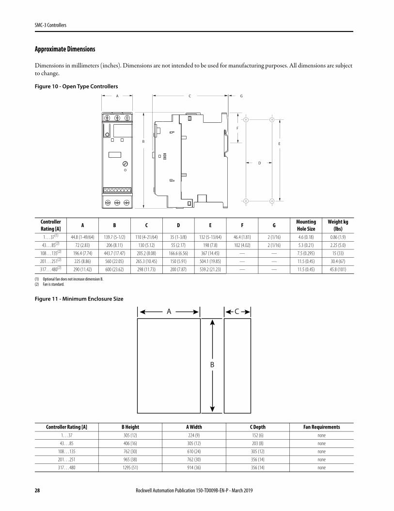
Controller Rating [A] B Height A Width C Depth Fan Requirements1…37 305 (12) 224 (9) 152 (6) none
43…85 406 (16) 305 (12) 203 (8) none
108…135 762 (30) 610 (24) 305 (12) none
201…251 965 (38) 762 (30) 356 (14) none
317…480 1295 (51) 914 (36) 356 (14) none
C G
E
D
A
B
F
A
B
C
28 Rockwell Automation Publication 150-TD009B-EN-P - March 2019
SMC Flex Controllers
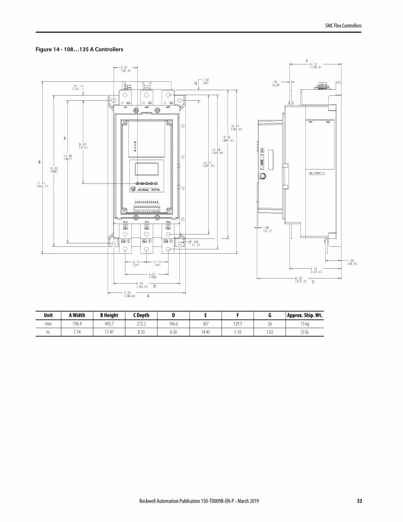
SMC Flex Controllers
The SMC Flex controller is modular so that it can help simplify installation and commissioning. A built-in LCD display, keypad, and flexible communications provide optimized configuration, advanced performance, diagnostics, and protection. Three-phase control, electronic overload, and integrated bypass along with removable control module, power modules, and fan assembly are combined in a cost-effective package for your demanding applications.
Modes of operation include the following:
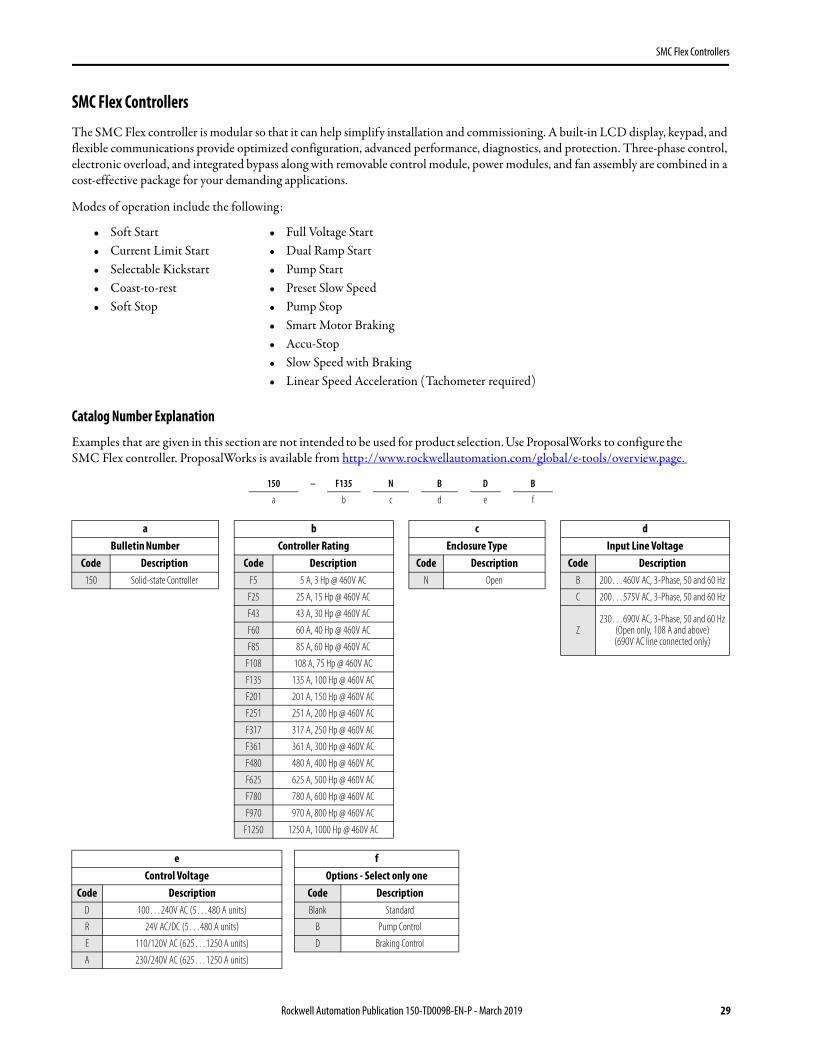
Catalog Number Explanation
Examples that are given in this section are not intended to be used for product selection. Use ProposalWorks to configure the SMC Flex controller. ProposalWorks is available from http://www.rockwellautomation.com/global/e-tools/overview.page.
• Soft Start • Full Voltage Start• Current Limit Start • Dual Ramp Start• Selectable Kickstart • Pump Start• Coast-to-rest • Preset Slow Speed• Soft Stop • Pump Stop
• Smart Motor Braking• Accu-Stop• Slow Speed with Braking• Linear Speed Acceleration (Tachometer required)
150 – F135 N B D B
a b c d e f
a b c dBulletin Number Controller Rating Enclosure Type Input Line Voltage
Code Description Code Description Code Description Code Description150 Solid-state Controller F5 5 A, 3 Hp @ 460V AC N Open B 200…460V AC, 3-Phase, 50 and 60 Hz
F25 25 A, 15 Hp @ 460V AC C 200…575V AC, 3-Phase, 50 and 60 Hz
F43 43 A, 30 Hp @ 460V AC
Z230…690V AC, 3-Phase, 50 and 60 Hz
(Open only, 108 A and above)(690V AC line connected only)
F60 60 A, 40 Hp @ 460V AC
F85 85 A, 60 Hp @ 460V AC
F108 108 A, 75 Hp @ 460V AC
F135 135 A, 100 Hp @ 460V AC
F201 201 A, 150 Hp @ 460V AC
F251 251 A, 200 Hp @ 460V AC
F317 317 A, 250 Hp @ 460V AC
F361 361 A, 300 Hp @ 460V AC
F480 480 A, 400 Hp @ 460V AC
F625 625 A, 500 Hp @ 460V AC
F780 780 A, 600 Hp @ 460V AC
F970 970 A, 800 Hp @ 460V AC
F1250 1250 A, 1000 Hp @ 460V AC
e fControl Voltage Options - Select only one
Code Description Code DescriptionD 100…240V AC (5…480 A units) Blank Standard
R 24V AC/DC (5…480 A units) B Pump Control
E 110/120V AC (625…1250 A units) D Braking Control
A 230/240V AC (625…1250 A units)
Rockwell Automation Publication 150-TD009B-EN-P - March 2019 29
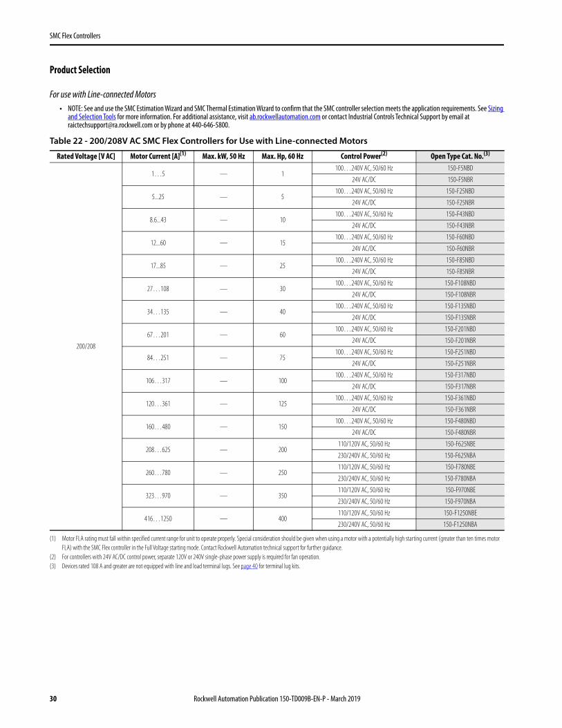
For use with Line-connected Motors• NOTE: See and use the SMC Estimation Wizard and SMC Thermal Estimation Wizard to confirm that the SMC controller selection meets the application requirements. See Sizing
and Selection Tools for more information. For additional assistance, visit ab.rockwellautomation.com or contact Industrial Controls Technical Support by email at [email protected] or by phone at 440-646-5800.
Table 22 - 200/208V AC SMC Flex Controllers for Use with Line-connected Motors
Rated Voltage [V AC] Motor Current [A](1)
(1) Motor FLA rating must fall within specified current range for unit to operate properly. Special consideration should be given when using a motor with a potentially high starting current (greater than ten times motor FLA) with the SMC Flex controller in the Full Voltage starting mode. Contact Rockwell Automation technical support for further guidance.
Max. kW, 50 Hz Max. Hp, 60 Hz Control Power(2)
(2) For controllers with 24V AC/DC control power, separate 120V or 240V single-phase power supply is required for fan operation.
Open Type Cat. No.(3)
(3) Devices rated 108 A and greater are not equipped with line and load terminal lugs. See page 40 for terminal lug kits.
200/208
1…5 — 1100…240V AC, 50/60 Hz 150-F5NBD
24V AC/DC 150-F5NBR
5...25 — 5100…240V AC, 50/60 Hz 150-F25NBD
24V AC/DC 150-F25NBR
8.6...43 — 10100…240V AC, 50/60 Hz 150-F43NBD
24V AC/DC 150-F43NBR
12...60 — 15100…240V AC, 50/60 Hz 150-F60NBD
24V AC/DC 150-F60NBR
17...85 — 25100…240V AC, 50/60 Hz 150-F85NBD
24V AC/DC 150-F85NBR
27…108 — 30100…240V AC, 50/60 Hz 150-F108NBD
24V AC/DC 150-F108NBR
34…135 — 40100…240V AC, 50/60 Hz 150-F135NBD
24V AC/DC 150-F135NBR
67…201 — 60100…240V AC, 50/60 Hz 150-F201NBD
24V AC/DC 150-F201NBR
84…251 — 75100…240V AC, 50/60 Hz 150-F251NBD
24V AC/DC 150-F251NBR
106…317 — 100100…240V AC, 50/60 Hz 150-F317NBD
24V AC/DC 150-F317NBR
120…361 — 125100…240V AC, 50/60 Hz 150-F361NBD
24V AC/DC 150-F361NBR
160…480 — 150100…240V AC, 50/60 Hz 150-F480NBD
24V AC/DC 150-F480NBR
208…625 — 200110/120V AC, 50/60 Hz 150-F625NBE
230/240V AC, 50/60 Hz 150-F625NBA
260…780 — 250110/120V AC, 50/60 Hz 150-F780NBE
230/240V AC, 50/60 Hz 150-F780NBA
323…970 — 350110/120V AC, 50/60 Hz 150-F970NBE
230/240V AC, 50/60 Hz 150-F970NBA
416…1250 — 400110/120V AC, 50/60 Hz 150-F1250NBE
230/240V AC, 50/60 Hz 150-F1250NBA
30 Rockwell Automation Publication 150-TD009B-EN-P - March 2019
Table 23 - 230V AC SMC Flex Controllers for Use with Line-connected Motors
Rated Voltage [V AC] Motor Current [A](1)
(1) Motor FLA rating must fall within specified current range for unit to operate properly. Special consideration should be given when using a motor with a potentially high starting current (greater than ten times motor FLA) with the SMC Flex controller. Contact Rockwell Automation technical support for further guidance.
Max. kW, 50 Hz Max. Hp, 60 Hz Control Power(2)
(2) For controllers with 24V AC/DC control power, separate 120V or 240V single-phase power supply is required for fan operation.
Open Type Cat. No.(3)
(3) Devices rated 108 A and greater are not equipped with line and load terminal lugs. See page 40 for terminal lug kits.
Rockwell Automation Publication 150-TD009B-EN-P - March 2019 31
SMC Flex Controllers
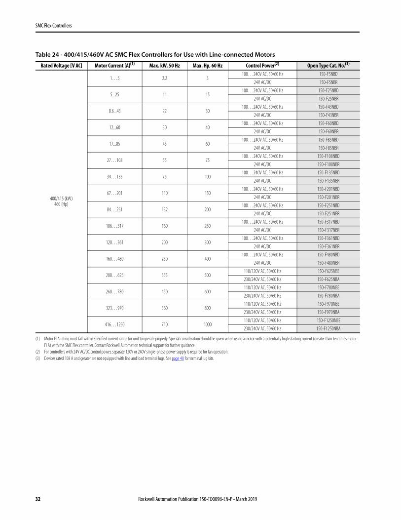
Table 24 - 400/415/460V AC SMC Flex Controllers for Use with Line-connected Motors
Rated Voltage [V AC] Motor Current [A](1)
(1) Motor FLA rating must fall within specified current range for unit to operate properly. Special consideration should be given when using a motor with a potentially high starting current (greater than ten times motor FLA) with the SMC Flex controller. Contact Rockwell Automation technical support for further guidance.
Max. kW, 50 Hz Max. Hp, 60 Hz Control Power(2)
(2) For controllers with 24V AC/DC control power, separate 120V or 240V single-phase power supply is required for fan operation.
Open Type Cat. No.(3)
(3) Devices rated 108 A and greater are not equipped with line and load terminal lugs. See page 40 for terminal lug kits.
32 Rockwell Automation Publication 150-TD009B-EN-P - March 2019
SMC Flex Controllers
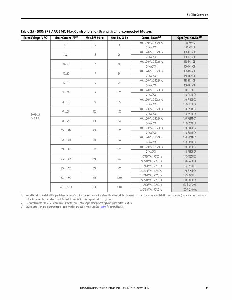
Table 25 - 500/575V AC SMC Flex Controllers for Use with Line-connected Motors
Rated Voltage [V AC] Motor Current [A](1)
(1) Motor FLA rating must fall within specified current range for unit to operate properly. Special consideration should be given when using a motor with a potentially high starting current (greater than ten times motor FLA) with the SMC Flex controller. Contact Rockwell Automation technical support for further guidance.
Max. kW, 50 Hz Max. Hp, 60 Hz Control Power(2)
(2) For controllers with 24V AC/DC control power, separate 120V or 240V single-phase power supply is required for fan operation.
Open Type Cat. No.(3)
(3) Devices rated 108 A and greater are not equipped with line and load terminal lugs. See page 40 for terminal lug kits.
Rockwell Automation Publication 150-TD009B-EN-P - March 2019 33
SMC Flex Controllers
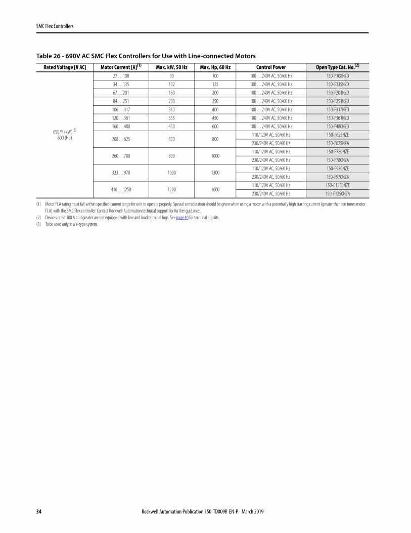
Table 26 - 690V AC SMC Flex Controllers for Use with Line-connected Motors
Rated Voltage [V AC] Motor Current [A](1)
(1) Motor FLA rating must fall within specified current range for unit to operate properly. Special consideration should be given when using a motor with a potentially high starting current (greater than ten times motor FLA) with the SMC Flex controller. Contact Rockwell Automation technical support for further guidance.
Max. kW, 50 Hz Max. Hp, 60 Hz Control Power Open Type Cat. No.(2)
(2) Devices rated 108 A and greater are not equipped with line and load terminal lugs. See page 40 for terminal lug kits.
34 Rockwell Automation Publication 150-TD009B-EN-P - March 2019
SMC Flex Controllers
For Use with Delta-connected Motors• NOTE: See and use the SMC Estimation Wizard and SMC Thermal Estimation Wizard to confirm that the SMC controller selection meets the application requirements. See Sizing
and Selection Tools for more information. For additional assistance, visit ab.rockwellautomation.com or contact Industrial Controls Technical Support by email at [email protected] or by phone at 440-646-5800.
.
Table 27 - 200/208V AC SMC Flex Controllers for Use with Delta-connected Motors
Rated Voltage [V AC] Motor Current [A](1)
(1) Motor FLA rating must fall within specified current range for unit to operate properly. Special consideration should be given when using a motor with a potentially high starting current (greater than ten times motor FLA) with the SMC Flex controller. Contact Rockwell Automation technical support for further guidance.
Max. kW, 50 Hz Max. Hp, 60 Hz Control Power(2)
(2) For controllers with 24V AC/DC control power, separate 120V or 240V single-phase power supply is required for fan operation.
Open Type Cat. No.(3)
(3) Devices rated 108 A and greater are not equipped with line and load terminal lugs. See page 40 for terminal lug kits.
200/208
1.7…8.7 — 2100…240V AC, 50/60 Hz 150-F5NBD
24V AC/DC 150-F5NBR
8.7…43 — 10100…240V AC, 50/60 Hz 150-F25NBD
24V AC/DC 150-F25NBR
14.9…74 — 20100…240V AC, 50/60 Hz 150-F43NBD
24V AC/DC 150-F43NBR
20.8…104 — 30100…240V AC, 50/60 Hz 150-F60NBD
24V AC/DC 150-F60NBR
29.4…147 — 40100…240V AC, 50/60 Hz 150-F85NBD
24V AC/DC 150-F85NBR
47…187 — 60100…240V AC, 50/60 Hz 150-F108NBD
24V AC/DC 150-F108NBR
59…234 — 75100…240V AC, 50/60 Hz 150-F135NBD
24V AC/DC 150-F135NBR
116…348 — 100100…240V AC, 50/60 Hz 150-F201NBD
24V AC/DC 150-F201NBR
145…435 — 150100…240V AC, 50/60 Hz 150-F251NBD
24V AC/DC 150-F251NBR
183…549 — 200100…240V AC, 50/60 Hz 150-F317NBD
24V AC/DC 150-F317NBR
208…625 — 200100…240V AC, 50/60 Hz 150-F361NBD
24V AC/DC 150-F361NBR
277…831 — 300100…240V AC, 50/60 Hz 150-F480NBD
24V AC/DC 150-F480NBR
283…850 — 300110/120V AC, 50/60 Hz 150-F625NBE
230/240V AC, 50/60 Hz 150-F625NBA
300…900 — 300110/120V AC, 50/60 Hz 150-F780NBE
230/240V AC, 50/60 Hz 150-F780NBA
400…1200 — 400110/120V AC, 50/60 Hz 150-F970NBE
230/240V AC, 50/60 Hz 150-F970NBA
533…1600 — 500110/120V AC, 50/60 Hz 150-F1250NBE
230/240V AC, 50/60 Hz 150-F1250NBA
Rockwell Automation Publication 150-TD009B-EN-P - March 2019 35
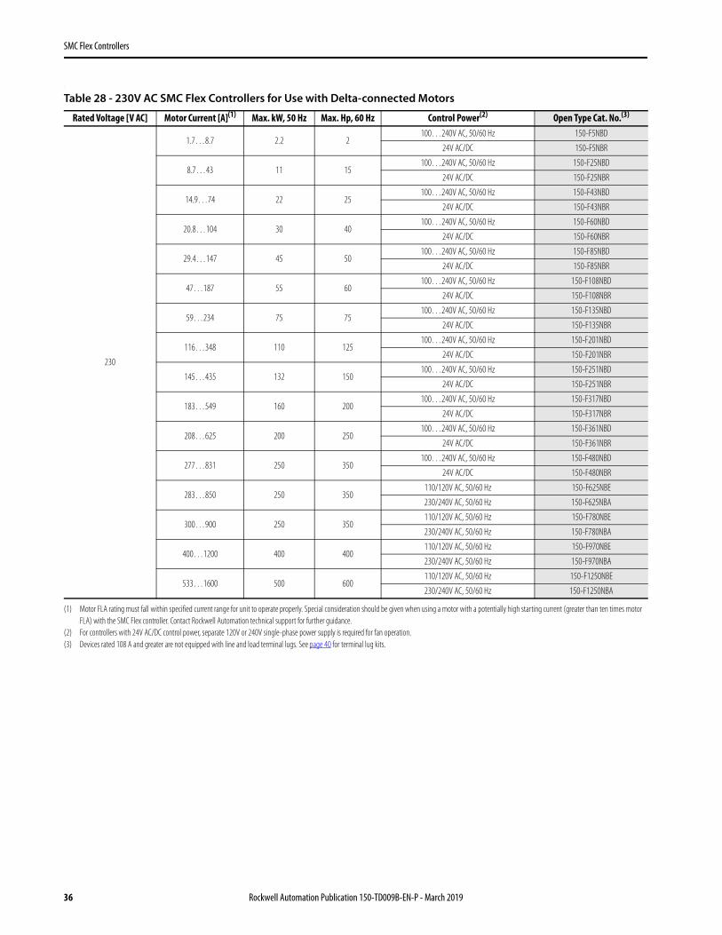
Table 28 - 230V AC SMC Flex Controllers for Use with Delta-connected Motors
Rated Voltage [V AC] Motor Current [A](1)
(1) Motor FLA rating must fall within specified current range for unit to operate properly. Special consideration should be given when using a motor with a potentially high starting current (greater than ten times motor FLA) with the SMC Flex controller. Contact Rockwell Automation technical support for further guidance.
Max. kW, 50 Hz Max. Hp, 60 Hz Control Power(2)
(2) For controllers with 24V AC/DC control power, separate 120V or 240V single-phase power supply is required for fan operation.
Open Type Cat. No.(3)
(3) Devices rated 108 A and greater are not equipped with line and load terminal lugs. See page 40 for terminal lug kits.
36 Rockwell Automation Publication 150-TD009B-EN-P - March 2019
SMC Flex Controllers
Table 29 - 400/415/460V AC SMC Flex Controllers for Use with Delta-connected Motors
Rated Voltage [V AC] Motor Current [A](1)
(1) Motor FLA rating must fall within specified current range for unit to operate properly. Special consideration should be given when using a motor with a potentially high starting current (greater than ten times motor FLA) with the SMC Flex controller. Contact Rockwell Automation technical support for further guidance.
Max. kW, 50 Hz Max. Hp, 60 Hz Control Power(2)
(2) For controllers with 24V AC/DC control power, separate 120V or 240V single-phase power supply is required for fan operation.
Open Type Cat. No.(3)
(3) Devices rated 108 A and greater are not equipped with line and load terminal lugs. See page 40 for terminal lug kits.
Rockwell Automation Publication 150-TD009B-EN-P - March 2019 37
SMC Flex Controllers
Table 30 - 500/575V AC SMC Flex Controllers for Use with Delta-connected Motors
Rated Voltage [V AC] Motor Current [A](1)
(1) Motor FLA rating must fall within specified current range for unit to operate properly. Special consideration should be given when using a motor with a potentially high starting current (greater than ten times motor FLA) with the SMC Flex controller. Contact Rockwell Automation technical support for further guidance.
Max. kW, 50 Hz Max. Hp, 60 Hz Control Power(2)
(2) For controllers with 24V AC/DC control power, separate 120V or 240V single-phase power supply is required for fan operation.
Open Type Cat. No.(3)
(3) Devices rated 108 A and greater are not equipped with line and load terminal lugs. See page 40 for terminal lug kits.
38 Rockwell Automation Publication 150-TD009B-EN-P - March 2019
SMC Flex Controllers
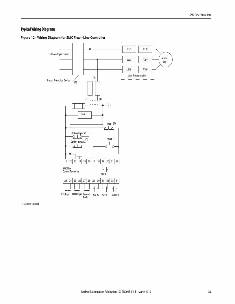
Typical Wiring Diagrams
Figure 12 - Wiring Diagram for SMC Flex—Line Controller
(1) Customer supplied.
Motor(1)
(1)
(1)
(1) (1)
(1)
(1)
(1) (1)
SMC Flex Controller
Branch Protection Device
3-Phase Input Power
Fan
Stop
Start
Option Input #1
Option Input #2
SMC Flex Control Terminals
Aux #1
Aux #2 Aux #3 Aux #4PTC Input TACH Input Ground Fault
Rockwell Automation Publication 150-TD009B-EN-P - March 2019 39
SMC Flex Controllers
Accessories
Protective Modules
The same protective module mounts on the line or load side of the SMC Flex controller. Use of protective modules is highly recommended. For applications that require both line and load side protection, you must order two protective modules.
• Note: You must not place protective modules on the load (motor) side of an SMC Flex controller when using an inside-the-delta connection or with pump or braking control options.
Terminal Lug Kits
IEC Line or Load Terminal Covers
Current Rating [A] Description Cat. No.5…85
480V Protective Module150-F84
108…1250 150-F84L
5…85600V Protective Module
150-F86
108…1250 150-F86L
Connection Type
Current Range [A](1)
(1) 5…85 A units have box lugs standard. No additional lugs are required.
Wire Size RangeTotal No. of Terminal Lugs Possible Each Side Pkg.
Qty.Cat. No.
Line Side Load Side
Line
108…135(2)
(2) When a multi-conductor lug is required, refer to the User Manual for appropriate lug catalog number.
(6) When connected in an inside-the-delta configuration, use Cat. No. 199-LG1 for load-side connections (T1…T6).
150-LGSMC
625…780 #4…500 MCM AWG25 mm2…240 mm2 6(4)
(4) For 625…1250 A inside-the-delta connections, terminal blocks are required for line-side connections. For fuse-protected controllers, use Allen-Bradley Cat. No. 1492-BG (625…780 A devices: 2 per phase; 970…1250 A devices, 4 per phase). For circuit breaker-protected controllers, use Cooper Bussmann Cat. No. 16504-2 (625…780 A devices: 1 per phase; 970…1250 A devices, 2 per phase).
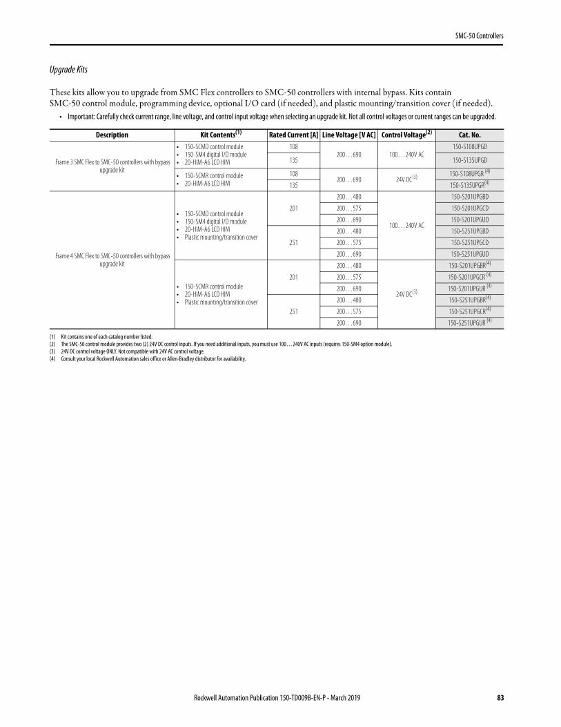
These kits allow you to upgrade from SMC Flex controllers to SMC-50 controllers with internal bypass. Kits contain SMC-50 control module, programming device, optional I/O card (if needed) and plastic mounting/transition cover (if needed).
• Important: Carefully check current range, line voltage and control input voltage when selecting an upgrade kit. Not all control voltages or current ranges can be upgraded.
Description Kit Contents(1)
(1) Kit contains one of each catalog number listed.
Rated Current [A] Line Voltage [V AC] Control Voltage(2)
(2) The SMC-50 control module provides two (2) 24V DC control inputs. If you need additional inputs, you must use 100…240V AC inputs (requires 150-SM4 option module).
Cat. No.
Frame 3 SMC Flex to SMC-50 controllers with bypass upgrade kit
• 150-SCMD control module• 150-SM4 digital I/O module• 20-HIM-A6 LCD HIM
108200…690 100…240V AC
150-S108UPGD
135 150-S135UPGD
• 150-SCMR control module• 20-HIM-A6 LCD HIM
108200…690 24V DC(3)
(3) 24V DC control voltage ONLY. Not compatible with 24V AC control voltage.
150-S108UPGR (4)
(4) Consult your local Rockwell Automation sales office or Allen-Bradley distributor for availability.
135 150-S135UPGR(4)
Frame 4 SMC Flex to SMC-50 controllers with bypass upgrade kit
• 150-SCMD control module• 150-SM4 digital I/O module• 20-HIM-A6 LCD HIM• Plastic mounting/transition cover
201
200…480
100…240V AC
150-S201UPGBD
200…575 150-S201UPGCD
200…690 150-S201UPGUD
251
200…480 150-S251UPGBD
200…575 150-S251UPGCD
200…690 150-S251UPGUD
• 150-SCMR control module• 20-HIM-A6 LCD HIM• Plastic mounting/transition cover
201
200…480
24V DC(3)
150-S201UPGBR(4)
200…575 150-S201UPGCR (4)
200…690 150-S201UPGUR (4)
251
200…480 150-S251UPGBR(4)
200…575 150-S251UPGCR(4)
200…690 150-S251UPGUR (4)
42 Rockwell Automation Publication 150-TD009B-EN-P - March 2019
SMC Flex Controllers
Specifications
Table 31 - SMC Flex Feature Specifications
Attribute DescriptionStandard Features
InstallationPower Wiring standard squirrel-cage induction motor or a Wye-Delta, six-lead motor
Control Wiring 2- and 3-wire control for a wide variety of applications
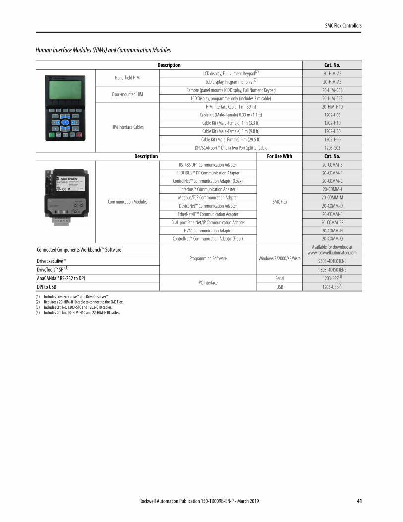
Configuration/SetupKeypad Front keypad with backlit LCD display. Optional 20-HIM-A module can be connected using the available DPI port.
Software parameter values are downloaded to the SMC Flex controller by using the Connected Components Workbench, DriveTools, and DriveExplorer programming software packages
Communications One DPI provided for connection to optional human interface and one DPI provided for connection to communication modules.
Starting and Stopping Modes
Soft StartCurrent Limit Start
Dual RampFull Voltage
Linear Speed AccelerationPreset Slow Speed
Soft Stop
Protection and Diagnostics Power loss, line fault, voltage unbalance, excessive starts/hour, phase reversal, undervoltage, overvoltage, controller temp, stall, jam, open gate, overload, underload, communication fault.
Metering Amps, volts, kW, kWh, MW, MWH, elapsed time, power factor, motor thermal capacity usage.
Status Indication Stopped, starting, stopping, at speed, alarm, and fault.
Auxiliary Contacts Four fully programmable contacts as normal/up-to-speed/fault/alarm/network (N.O./N.C.), or external bypass (N.O. only).
Optional Features
Pump Control Helps reduce fluid surges in centrifugal pumping systems during starting and stopping period. Starting time is adjustable from 0…30 s. Stopping time is adjustable from 0…120 s.
Braking Control(1)
(1) Not intended to be used as an emergency stop. See the applicable standards for emergency stop requirements.
SMB Smart Motor Braking
Provides motor braking without additional equipment for applications that require the motor to stop quickly. Braking current is adjustable from 0…400% of the motor’s full-load current rating.
Accu-StopProvides controlled position stopping. During stopping, braking torque is applied to the motor until it reaches preset slow speed (7% or 15% of
rated speed) and holds the motor at this speed until a stop command is given. Braking torque is then applied until the motor reaches zero speed. Braking current is programmable from 0…450% of full-load current.
Slow Speed with Braking Used on applications that require slow speed (in the forward direction) for positioning or alignment and also require braking control to stop.
Rockwell Automation Publication 150-TD009B-EN-P - March 2019 43
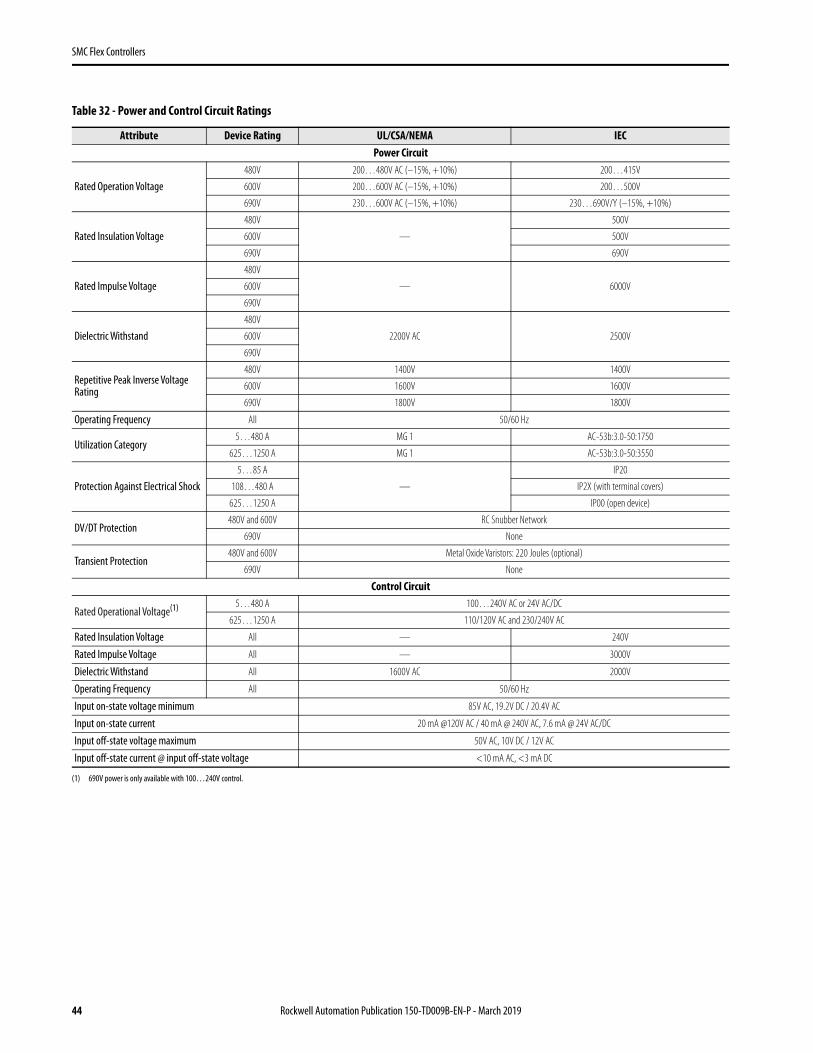
Rated Operation Voltage480V 200…480V AC (–15%, +10%) 200…415V
600V 200…600V AC (–15%, +10%) 200…500V
690V 230…600V AC (–15%, +10%) 230…690V/Y (–15%, +10%)
Rated Insulation Voltage480V
—
500V
600V 500V
690V 690V
Rated Impulse Voltage480V
— 6000V600V
690V
Dielectric Withstand480V
2200V AC 2500V600V
690V
Repetitive Peak Inverse Voltage Rating
480V 1400V 1400V
600V 1600V 1600V
690V 1800V 1800V
Operating Frequency All 50/60 Hz
Utilization Category5…480 A MG 1 AC-53b:3.0-50:1750
625…1250 A MG 1 AC-53b:3.0-50:3550
Protection Against Electrical Shock5…85 A
—
IP20
108…480 A IP2X (with terminal covers)
625…1250 A IP00 (open device)
DV/DT Protection480V and 600V RC Snubber Network
690V None
Transient Protection480V and 600V Metal Oxide Varistors: 220 Joules (optional)
690V None
Control Circuit
Rated Operational Voltage(1)
(1) 690V power is only available with 100…240V control.
5…480 A 100…240V AC or 24V AC/DC
625…1250 A 110/120V AC and 230/240V AC
Rated Insulation Voltage All — 240V
Rated Impulse Voltage All — 3000V
Dielectric Withstand All 1600V AC 2000V
Operating Frequency All 50/60 Hz
Input on-state voltage minimum 85V AC, 19.2V DC / 20.4V AC
Input on-state current 20 mA @120V AC / 40 mA @ 240V AC, 7.6 mA @ 24V AC/DC
Input off-state voltage maximum 50V AC, 10V DC / 12V AC
Input off-state current @ input off-state voltage <10 mA AC, <3 mA DC
44 Rockwell Automation Publication 150-TD009B-EN-P - March 2019
SMC Flex Controllers
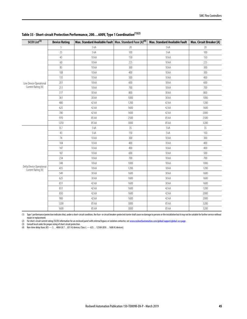
Table 33 - Short-circuit Protection Performance, 200…600V, Type 1 Coordination(1)(2)
(1) Type 1 performance/protection indicates that, under a short-circuit condition, the fuse- or circuit breaker-protected starter shall cause no damage to persons or the installation but it may not be suitable for further service without repair or replacement.
(2) For short-circuit current rating (SCCR) information for an enclosed panel with external bypass or isolation contactor, see www.rockwellautomation.com/global/support/global-sccr.page.
SCCR List(3)
(3) Consult local codes for proper sizing of short circuit protection.
Device Rating Max. Standard Available Fault Max. Standard Fuse [A](4)
(4) Non-time delay fuses (K5 — 5…480A (8.7…831 A) devices; Class L — 625…1250A (850…1600 A) devices).
Max. Standard Available Fault Max. Circuit Breaker [A]
Line Device Operational Current Rating [A]
5 5 kA 20 5 kA 20
25 5 kA 100 5 kA 100
43 10 kA 150 10 kA 150
60 10 kA 225 10 kA 225
85 10 kA 300 10 kA 300
108 10 kA 400 10 kA 300
135 10 kA 500 10 kA 400
201 18 kA 600 18 kA 600
251 18 kA 700 18 kA 700
317 30 kA 800 30 kA 800
361 30 kA 1000 30 kA 1000
480 42 kA 1200 42 kA 1200
625 42 kA 1600 42 kA 1600
780 42 kA 1600 42 kA 2000
970 85 kA 2500 85 kA 2500
1250 85 kA 3000 85 kA 3200
Delta Device Operational Current Rating [A]
8.7 5 kA 35 5 kA 35
43 5 kA 150 5 kA 150
74 10 kA 300 10 kA 300
104 10 kA 400 10 kA 400
147 10 kA 400 10 kA 400
187 10 kA 600 10 kA 500
234 10 kA 700 10 kA 700
348 18 kA 1000 18 kA 1000
435 18 kA 1200 18 kA 1200
549 30 kA 1600 30 kA 1600
625 30 kA 1600 30 kA 1600
831 42 kA 1600 30 kA 1600
831 42 kA 1600 42 kA 1200
850 42 kA 1600 42 kA 2000
900 42 kA 1600 42 kA 2000
1200 85 kA 3000 85 kA 3200
1600 85 kA 3000 85 kA 3200
Rockwell Automation Publication 150-TD009B-EN-P - March 2019 45
Table 34 - Short-circuit Protection Performance, 200…600V, Type 1 Coordination
SCPD Performance(1)
(1) Consult local codes for proper sizing of short-circuit protection.
Type 1 Ratings(2)
(2) Basic Requirements for Type 1 Coordination: Under the short-circuit condition, the starter shall cause no danger to persons or to the installation. The starter may not be suitable for further service without repair or replacement of parts. For further details, refer to UL 508/CSA C22.2 No. 14 and EN 60947-4-2.
Motor Connection Type
Cat. No.Current
Rating [A]
Class J or Class L Fuse(3)
(3) High Capacity fault ratings when used with time delay Class J or time delay Class L fuse.
Inverse Time (Thermal Magnetic) Circuit Breaker 480V, 65 kA Max.
Max. High Capacity Available Fault (600V) [kA]
Max. Current [A] Max. Current [A] Cat. No. Rating Plug Cat. No.
46 Rockwell Automation Publication 150-TD009B-EN-P - March 2019
SMC Flex Controllers
Table 35 - Short-circuit Protection Performance, 690V, Type 1 Coordination(1)
(1) Type 1 performance/protection indicates that, under a short-circuit condition, the fuse- or circuit breaker-protected starter shall cause no damage to persons or the installation but it may not be suitable for further service without repair or replacement.
SCCR List(2)
(2) Consult local codes for proper sizing of short circuit protection.
Device RatingMax. Standard Available Fault
Max. Ampere Tested — North American Style Max. Ampere Tested — European Style
Maximum FLC
108 70 kA A070URD33xxx500 6,9 gRB 73xxx4006,6URD33xxx500
135 70 kA A070URD33xxx500 6,9 gRB 73xxx4006,6URD33xxx500
201 70 kA A070URD33xxx700 6,9 gRB 73xxx6306,6URD33xxx700
251 70 kA A070URD33xxx700 6,9 gRB 73xxx6306,6URD33xxx700
317 70 kA A070URD33xxx900 6,9 gRB 73xxx8006,6URD33xxx900
361 70 kA A070URD33xxx900 6,9 gRB 73xxx8006,6URD33xxx900
480 70 kA A070D33xxx1250A100URD73xxx1250
9 URD 73xxx12506,6URD33xxx1250
625 70 kA A070URD33xxx1400 6,6URD33xxx1400
780 70 kA A070URD33xxx1400 6,6URD33xxx1400
970 85 kA Two fuses in parallel A070URD33xxx1250 Two fuses in parallel 6,6URD33xxx1250
1250 85 kA Two fuses in parallel A070URD33xxx1250 Two fuses in parallel 6,6URD33xxx1250
Table 36 - Power Requirements
Device Rating [A] Control Power Description
Control Module1…480
100…240V AC (-15%, +10%) Transformer 75 VA
24V AC (-15%, +10%) Transformer 130 VA
24V DC (-15%, +10%)
Inrush Current 5 A
Inrush Time 250 ms
Transient Watts 60 W
Transient Time 500 ms
Steady State Watts 24 W
Minimum Allen-Bradley Power Supply 1606-XLP50E
625…1250 751 VA (recommended 800 VA)
Heatsink Fan(s)(1)
(1) Heatsink fans can be powered by either 110/120V AC or 220/240V AC.
5…135 A, 20 VA
201…251 A, 40 VA
317…480 A, 60 VA
625…1250 A, 150 VA
Rockwell Automation Publication 150-TD009B-EN-P - March 2019 47
SMC Flex Controllers
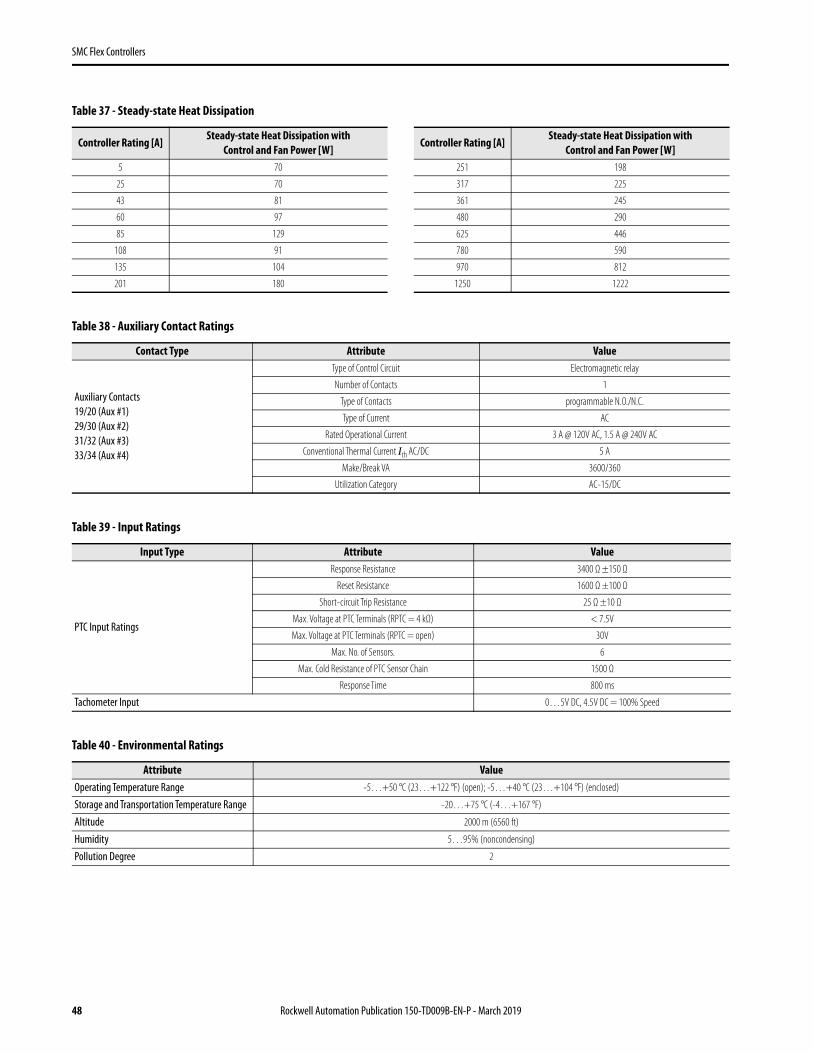
Table 37 - Steady-state Heat Dissipation
Controller Rating [A]Steady-state Heat Dissipation with
Control and Fan Power [W]Controller Rating [A]
Steady-state Heat Dissipation with Control and Fan Power [W]
Rockwell Automation Publication 150-TD009B-EN-P - March 2019 55
SMC Flex Controllers
Figure 17 - Dimensions: 625…780 A Controllers
Unit A Width B Height C Depth D E F G Approx. Ship. Wt.mm 596.9 1041.4 346.2 550.9 594.1 214.9 200.4 179 kg
in. 23.5 41.0 13.63 21.69 23.39 8.46 7.89 395 lb.
23.5023.50596,9596,9[ ]
41.0041.001041,41041,4[ ]
2.002.0050,850,8[ ]
4.004.00101,6101,6[ ]
1.201.2030,530,5[ ]
21.6921.69550,9550,9[ ]
1.641.6441,641,6[ ]
7.897.89200,4200,4[ ]
23.3923.39594,1594,1[ ]
38.4538.45976,6976,6[ ]
.90.902323[ ]
13.6313.63346,2346,2[ ]
2X 2X .25256,46,4[ ]
.787819,819,8[ ]
3.623.6292,192,1[ ]
8.468.46214,9214,9[ ]
3X 3X .2525.05.05[ ]
.39.391010[ ]
13.8613.86351,9351,9[ ]
14.5414.54369,4369,4[ ]
19.5419.54496,3496,3[ ]
29.0229.02737737[ ]
Ø.500.50012,712,7[ ]
Ø.531.53113,4913,49[ ]
7.357.35186,6186,6[ ]
14.3514.35364,4364,4[ ]
8.258.25209,5209,5[ ]
7.007.00177,8177,8[ ]
4X 4X 2.752.7569,869,8[ ]
4X 4X 3.003.0076,276,2[ ] Ø.734.734
18,6418,64[ ]
1.001.0025,425,4[ ]
SEE DETAIL ASEE DETAIL A
3X DETAIL A3X DETAIL A
#8-32 UNC-2B#8-32 UNC-2B
C
F
B
E
G
A
D
56 Rockwell Automation Publication 150-TD009B-EN-P - March 2019
SMC Flex Controllers
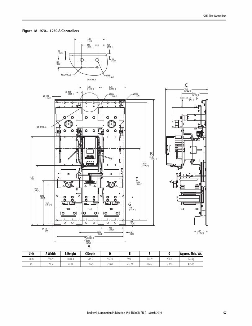
Figure 18 - 970…1250 A Controllers
Unit A Width B Height C Depth D E F G Approx. Ship. Wt.mm 596.9 1041.4 346.2 550.9 594.1 214.9 200.4 224 kg
in. 23.5 41.0 13.63 21.69 23.39 8.46 7.89 495 lb.
41.0041.001041,41041,4[ ]
23.3923.39594,1594,1[ ]
7.897.89200,4200,4[ ]
1.641.6441,641,6[ ]
.90.902323[ ]
21.6921.69550,9550,9[ ]
23.5023.50596,9596,9[ ]
3X 3X .15.153,83,8[ ]
13.8613.86351,9351,9[ ]
14.5414.54369,4369,4[ ]
19.5419.54496,3496,3[ ]
29.0229.02737737[ ]
4.574.57116,2116,2[ ]
8.468.46214,9214,9[ ]
2X 2X .25.256,46,4[ ]
13.6313.63346,2346,2[ ]
Ø.500.50012,712,7[ ]
2.502.5063,563,5[ ]
5.005.00127127[ ]
.74.7418,818,8[ ]
1.201.2030,530,5[ ]
.28.287,27,2[ ]
Ø.531.53113,4913,49[ ]
38.4538.45976,6976,6[ ]
4X 4X 2.252.2557,157,1[ ]
4X 4X 2.002.0050,850,8[ ] Ø.734.734
18,6418,64[ ]
8.258.25209,5209,5[ ]
7.007.00177,8177,8[ ]
7.357.35186,6186,6[ ]
14.3514.35364,4364,4[ ]
1.251.2531,831,8[ ]
SEE DETAIL ASEE DETAIL A
3X DETAIL A3X DETAIL A
#8-32 UNC-2B#8-32 UNC-2B
C
F
B
E
G
A
D
Rockwell Automation Publication 150-TD009B-EN-P - March 2019 57
SMC Flex Controllers
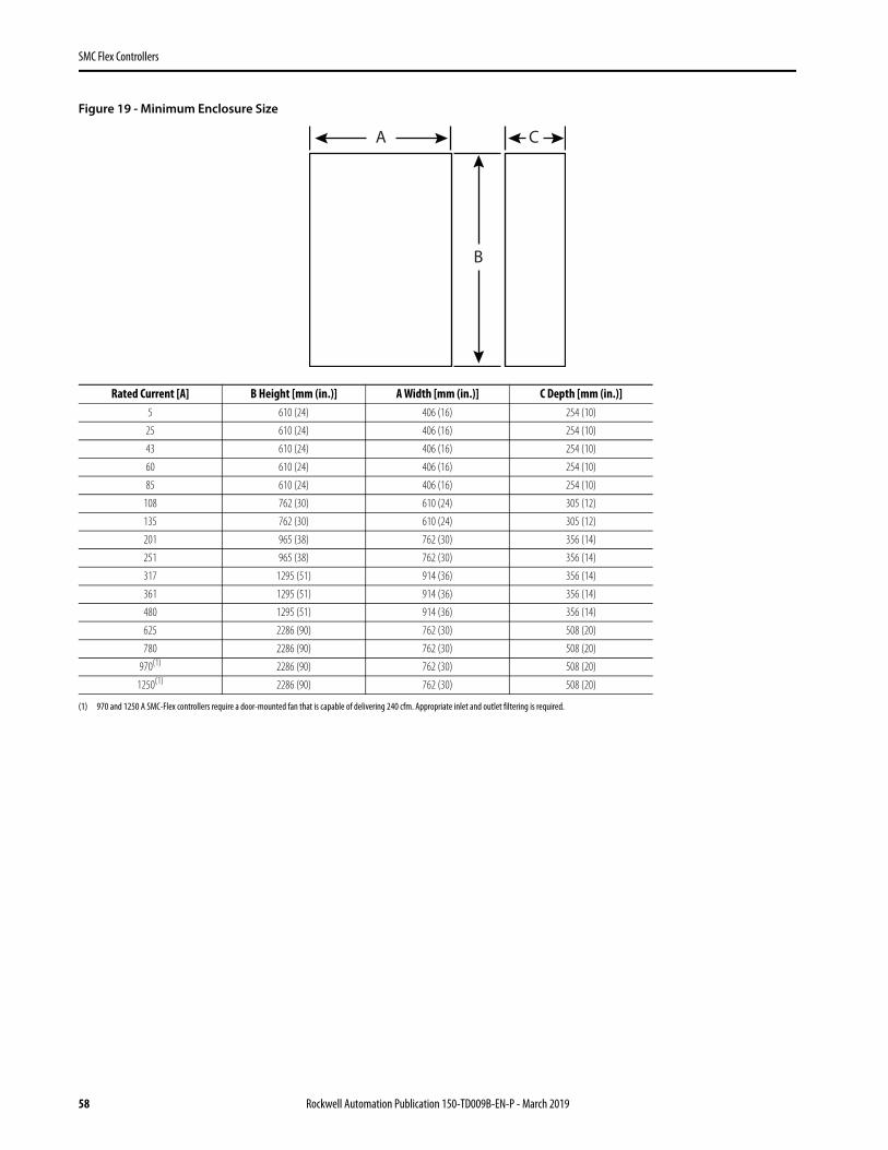
Figure 19 - Minimum Enclosure Size
Rated Current [A] B Height [mm (in.)] A Width [mm (in.)] C Depth [mm (in.)]5 610 (24) 406 (16) 254 (10)
25 610 (24) 406 (16) 254 (10)
43 610 (24) 406 (16) 254 (10)
60 610 (24) 406 (16) 254 (10)
85 610 (24) 406 (16) 254 (10)
108 762 (30) 610 (24) 305 (12)
135 762 (30) 610 (24) 305 (12)
201 965 (38) 762 (30) 356 (14)
251 965 (38) 762 (30) 356 (14)
317 1295 (51) 914 (36) 356 (14)
361 1295 (51) 914 (36) 356 (14)
480 1295 (51) 914 (36) 356 (14)
625 2286 (90) 762 (30) 508 (20)
780 2286 (90) 762 (30) 508 (20)
970(1)
(1) 970 and 1250 A SMC-Flex controllers require a door-mounted fan that is capable of delivering 240 cfm. Appropriate inlet and outlet filtering is required.
2286 (90) 762 (30) 508 (20)
1250(1) 2286 (90) 762 (30) 508 (20)
A
B
C
58 Rockwell Automation Publication 150-TD009B-EN-P - March 2019
SMC-50 Controllers
SMC-50 Controllers
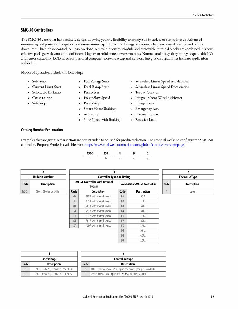
The SMC-50 controller has a scalable design, allowing you the flexibility to satisfy a wide variety of control needs. Advanced monitoring and protection, superior communications capabilities, and Energy Saver mode help increase efficiency and reduce downtime. Three-phase control, built-in overload, removable control module and removable terminal blocks are combined in a cost-effective package with your choice of internal bypass or solid-state power structures. Normal- and heavy-duty ratings, expandable I/O and sensor capability, LCD screen or personal computer software setup and network integration capabilities increase application scalability.
Modes of operation include the following:
Catalog Number Explanation
Examples that are given in this section are not intended to be used for product selection. Use ProposalWorks to configure the SMC-50 controller. ProposalWorks is available from http://www.rockwellautomation.com/global/e-tools/overview.page.
• Soft Start • Full Voltage Start • Sensorless Linear Speed Acceleration• Current Limit Start • Dual Ramp Start • Sensorless Linear Speed Deceleration• Selectable Kickstart • Pump Start • Torque Control• Coast-to-rest • Preset Slow Speed • Integral Motor Winding Heater• Soft Stop • Pump Stop • Energy Saver
• Smart Motor Braking • Emergency Run• Accu-Stop • External Bypass• Slow Speed with Braking • Resistive Load
150-S 135 N B Da b c d e
a b cBulletin Number Controller Type and Rating Enclosure Type
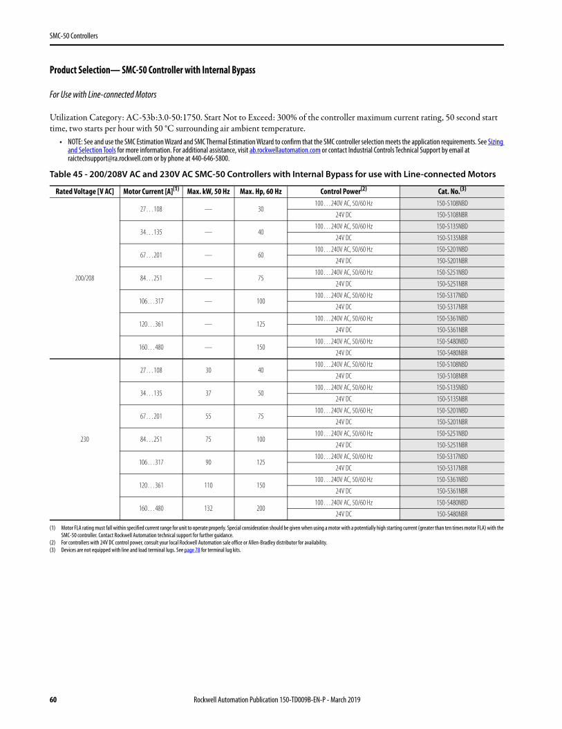
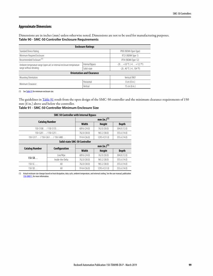
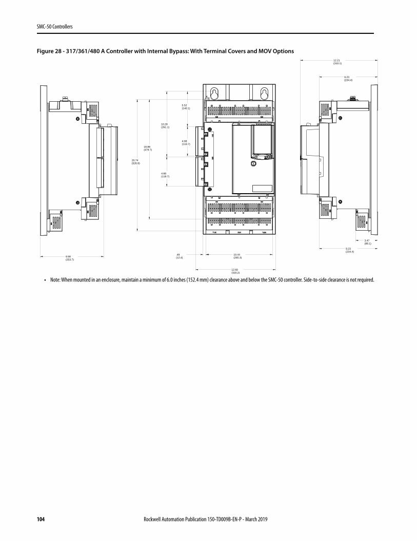
Product Selection— SMC-50 Controller with Internal Bypass
For Use with Line-connected Motors
Utilization Category: AC-53b:3.0-50:1750. Start Not to Exceed: 300% of the controller maximum current rating, 50 second start time, two starts per hour with 50 °C surrounding air ambient temperature.
• NOTE: See and use the SMC Estimation Wizard and SMC Thermal Estimation Wizard to confirm that the SMC controller selection meets the application requirements. See Sizing and Selection Tools for more information. For additional assistance, visit ab.rockwellautomation.com or contact Industrial Controls Technical Support by email at [email protected] or by phone at 440-646-5800.
Table 45 - 200/208V AC and 230V AC SMC-50 Controllers with Internal Bypass for use with Line-connected Motors
Rated Voltage [V AC] Motor Current [A](1)
(1) Motor FLA rating must fall within specified current range for unit to operate properly. Special consideration should be given when using a motor with a potentially high starting current (greater than ten times motor FLA) with the SMC-50 controller. Contact Rockwell Automation technical support for further guidance.
Max. kW, 50 Hz Max. Hp, 60 Hz Control Power(2)
(2) For controllers with 24V DC control power, consult your local Rockwell Automation sale office or Allen-Bradley distributor for availability.
Cat. No.(3)
(3) Devices are not equipped with line and load terminal lugs. See page 78 for terminal lug kits.
200/208
27…108 — 30100…240V AC, 50/60 Hz 150-S108NBD
24V DC 150-S108NBR
34…135 — 40100…240V AC, 50/60 Hz 150-S135NBD
24V DC 150-S135NBR
67…201 — 60100…240V AC, 50/60 Hz 150-S201NBD
24V DC 150-S201NBR
84…251 — 75100…240V AC, 50/60 Hz 150-S251NBD
24V DC 150-S251NBR
106…317 — 100100…240V AC, 50/60 Hz 150-S317NBD
24V DC 150-S317NBR
120…361 — 125100…240V AC, 50/60 Hz 150-S361NBD
24V DC 150-S361NBR
160…480 — 150100…240V AC, 50/60 Hz 150-S480NBD
24V DC 150-S480NBR
230
27…108 30 40100…240V AC, 50/60 Hz 150-S108NBD
24V DC 150-S108NBR
34…135 37 50100…240V AC, 50/60 Hz 150-S135NBD
24V DC 150-S135NBR
67…201 55 75100…240V AC, 50/60 Hz 150-S201NBD
24V DC 150-S201NBR
84…251 75 100100…240V AC, 50/60 Hz 150-S251NBD
24V DC 150-S251NBR
106…317 90 125100…240V AC, 50/60 Hz 150-S317NBD
24V DC 150-S317NBR
120…361 110 150100…240V AC, 50/60 Hz 150-S361NBD
24V DC 150-S361NBR
160…480 132 200100…240V AC, 50/60 Hz 150-S480NBD
24V DC 150-S480NBR
60 Rockwell Automation Publication 150-TD009B-EN-P - March 2019
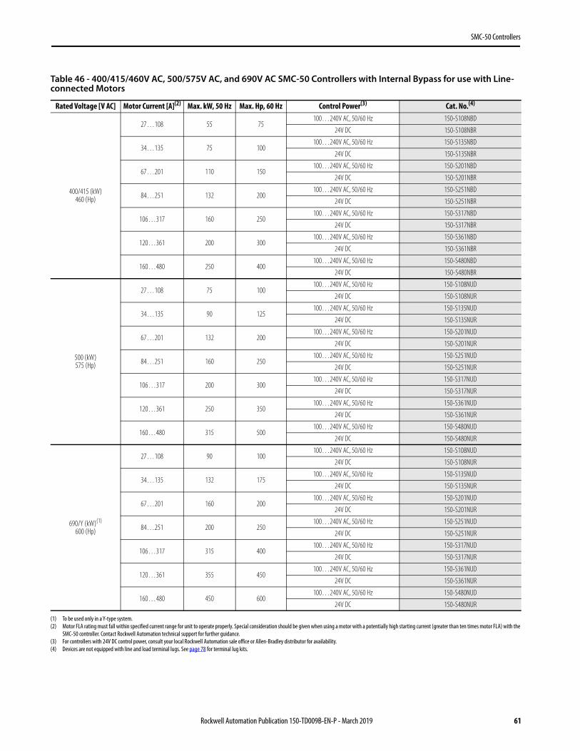
Table 46 - 400/415/460V AC, 500/575V AC, and 690V AC SMC-50 Controllers with Internal Bypass for use with Line-connected Motors
Rated Voltage [V AC] Motor Current [A](2)
(2) Motor FLA rating must fall within specified current range for unit to operate properly. Special consideration should be given when using a motor with a potentially high starting current (greater than ten times motor FLA) with the SMC-50 controller. Contact Rockwell Automation technical support for further guidance.
Max. kW, 50 Hz Max. Hp, 60 Hz Control Power(3)
(3) For controllers with 24V DC control power, consult your local Rockwell Automation sale office or Allen-Bradley distributor for availability.
Cat. No.(4)
(4) Devices are not equipped with line and load terminal lugs. See page 78 for terminal lug kits.
400/415 (kW)460 (Hp)
27…108 55 75100…240V AC, 50/60 Hz 150-S108NBD
24V DC 150-S108NBR
34…135 75 100100…240V AC, 50/60 Hz 150-S135NBD
24V DC 150-S135NBR
67…201 110 150100…240V AC, 50/60 Hz 150-S201NBD
24V DC 150-S201NBR
84…251 132 200100…240V AC, 50/60 Hz 150-S251NBD
24V DC 150-S251NBR
106…317 160 250100…240V AC, 50/60 Hz 150-S317NBD
24V DC 150-S317NBR
120…361 200 300100…240V AC, 50/60 Hz 150-S361NBD
24V DC 150-S361NBR
160…480 250 400100…240V AC, 50/60 Hz 150-S480NBD
24V DC 150-S480NBR
500 (kW)575 (Hp)
27…108 75 100100…240V AC, 50/60 Hz 150-S108NUD
24V DC 150-S108NUR
34…135 90 125100…240V AC, 50/60 Hz 150-S135NUD
24V DC 150-S135NUR
67…201 132 200100…240V AC, 50/60 Hz 150-S201NUD
24V DC 150-S201NUR
84…251 160 250100…240V AC, 50/60 Hz 150-S251NUD
24V DC 150-S251NUR
106…317 200 300100…240V AC, 50/60 Hz 150-S317NUD
24V DC 150-S317NUR
120…361 250 350100…240V AC, 50/60 Hz 150-S361NUD
24V DC 150-S361NUR
160…480 315 500100…240V AC, 50/60 Hz 150-S480NUD
24V DC 150-S480NUR
690/Y (kW)(1)
600 (Hp)
(1) To be used only in a Y-type system.
27…108 90 100100…240V AC, 50/60 Hz 150-S108NUD
24V DC 150-S108NUR
34…135 132 175100…240V AC, 50/60 Hz 150-S135NUD
24V DC 150-S135NUR
67…201 160 200100…240V AC, 50/60 Hz 150-S201NUD
24V DC 150-S201NUR
84…251 200 250100…240V AC, 50/60 Hz 150-S251NUD
24V DC 150-S251NUR
106…317 315 400100…240V AC, 50/60 Hz 150-S317NUD
24V DC 150-S317NUR
120…361 355 450100…240V AC, 50/60 Hz 150-S361NUD
24V DC 150-S361NUR
160…480 450 600100…240V AC, 50/60 Hz 150-S480NUD
24V DC 150-S480NUR
Rockwell Automation Publication 150-TD009B-EN-P - March 2019 61
SMC-50 Controllers
For Use with Delta-connected Motors
Utilization Category: AC-53b:3.0-50:1750. Start Not to Exceed: 300% of the controller maximum current rating, 50 second start time, two starts per hour with 50 °C surrounding air ambient temperature.
• NOTE: See and use the SMC Estimation Wizard and SMC Thermal Estimation Wizard to confirm that the SMC controller selection meets the application requirements. See Sizing and Selection Tools for more information. For additional assistance, visit ab.rockwellautomation.com or contact Industrial Controls Technical Support by email at [email protected] or by phone at 440-646-5800.
.
Table 47 - 200/208V AC and 230V AC SMC-50 Controllers with Internal Bypass for use with Delta-connected Motors
Rated Voltage [V AC] Motor Current [A](1)
(1) Motor FLA rating must fall within specified current range for unit to operate properly. Special consideration should be given when using a motor with a potentially high starting current (greater than ten times motor FLA) with the SMC-50 controller. Contact Rockwell Automation technical support for further guidance.
Max. kW, 50 Hz Max. Hp, 60 Hz Control Power(2)
(2) For controllers with 24V DC control power, consult your local Rockwell Automation sale office or Allen-Bradley distributor for availability.
Cat. No.(3)
(3) Devices are not equipped with line and load terminal lugs. See page 78 for terminal lug kits.
200/208
47…187 — 60100…240V AC, 50/60 Hz 150-S108NBD
24V DC 150-S108NBR
59…234 — 75100…240V AC, 50/60 Hz 150-S135NBD
24V DC 150-S135NBR
116…348 — 100100…240V AC, 50/60 Hz 150-S201NBD
24V DC 150-S201NBR
145…435 — 150100…240V AC, 50/60 Hz 150-S251NBD
24V DC 150-S251NBR
183…549 — 200100…240V AC, 50/60 Hz 150-S317NBD
24V DC 150-S317NBR
208…625 — 200100…240V AC, 50/60 Hz 150-S361NBD
24V DC 150-S361NBR
277…831 — 300100…240V AC, 50/60 Hz 150-S480NBD
24V DC 150-S480NBR
230
47…187 55 60100…240V AC, 50/60 Hz 150-S108NBD
24V DC 150-S108NBR
59…234 75 75100…240V AC, 50/60 Hz 150-S135NBD
24V DC 150-S135NBR
116…348 110 100100…240V AC, 50/60 Hz 150-S201NBD
24V DC 150-S201NBR
145…435 132 150100…240V AC, 50/60 Hz 150-S251NBD
24V DC 150-S251NBR
183…549 160 200100…240V AC, 50/60 Hz 150-S317NBD
24V DC 150-S317NBR
208…625 200 200100…240V AC, 50/60 Hz 150-S361NBD
24V DC 150-S361NBR
277…831 250 300100…240V AC, 50/60 Hz 150-S480NBD
24V DC 150-S480NBR
62 Rockwell Automation Publication 150-TD009B-EN-P - March 2019
Table 48 - 400/415/460V AC and 500/575V AC SMC-50 Controllers with Internal Bypass for use with Delta-connected Motors
Rated Voltage [V AC] Motor Current [A](1)
(1) Motor FLA rating must fall within specified current range for unit to operate properly. Special consideration should be given when using a motor with a potentially high starting current (greater than ten times motor FLA) with the SMC-50 controller. Contact Rockwell Automation technical support for further guidance.
Max. kW, 50 Hz Max. Hp, 60 Hz Control Power(2)
(2) For controllers with 24V DC control power, consult your local Rockwell Automation sale office or Allen-Bradley distributor for availability.
Cat. No.(3)
(3) Devices are not equipped with line and load terminal lugs. See page 78 for terminal lug kits.
400/415 (kW)460 (Hp)
47…187 90 125100…240V AC, 50/60 Hz 150-S108NBD
24V DC 150-S108NBR
59…234 132 150100…240V AC, 50/60 Hz 150-S135NBD
24V DC 150-S135NBR
116…348 160 250100…240V AC, 50/60 Hz 150-S201NBD
24V DC 150-S201NBR
145…435 250 350100…240V AC, 50/60 Hz 150-S251NBD
24V DC 150-S251NBR
183…549 315 450100…240V AC, 50/60 Hz 150-S317NBD
24V DC 150-S317NBR
208…625 355 500100…240V AC, 50/60 Hz 150-S361NBD
24V DC 150-S361NBR
277…831 450 700100…240V AC, 50/60 Hz 150-S480NBD
24V DC 150-S480NBR
500 (kW)575 (Hp)
47…187 132 150100…240V AC, 50/60 Hz 150-S108NUD
24V DC 150-S108NUR
59…234 160 200100…240V AC, 50/60 Hz 150-S135NUD
24V DC 150-S135NUR
116…348 250 350100…240V AC, 50/60 Hz 150-S201NUD
24V DC 150-S201NUR
145…435 315 400100…240V AC, 50/60 Hz 150-S251NUD
24V DC 150-S251NUR
183…549 400 500100…240V AC, 50/60 Hz 150-S317NUD
24V DC 150-S317NUR
208…625 450 600100…240V AC, 50/60 Hz 150-S361NUD
24V DC 150-S361NUR
277…831 560 900100…240V AC, 50/60 Hz 150-S480NUD
24V DC 150-S480NUR
Rockwell Automation Publication 150-TD009B-EN-P - March 2019 63
SMC-50 Controllers
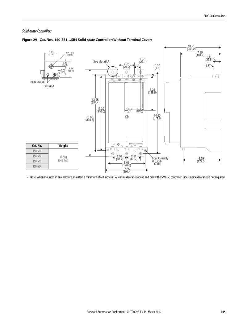
Product Selection—SMC-50 Solid-state Controller
For Use with Line-connected Motors
Normal/Standard Duty Ratings (for pumps, compressors, elevators, and short conveyors)
Utilization Category: AC-53a:3.5-10:99-2. Start Not to Exceed: 350% of the controller maximum current rating, 10 second start time, 99% ON load factor, two starts per hour with 40 °C surrounding air ambient temperature.
• NOTE: See and use the SMC Estimation Wizard and SMC Thermal Estimation Wizard to confirm that the SMC controller selection meets the application requirements. See Sizing and Selection Tools for more information. For additional assistance, visit ab.rockwellautomation.com or contact Industrial Controls Technical Support by email at [email protected] or by phone at 440-646-5800.
Table 49 - 200/208V AC SMC-50 Solid-state Controllers for Use with Line-connected Motors, Normal/Standard Duty
Rated Utilization Voltage [V AC] Motor Current [A](1)
(1) Motor FLA rating must fall within specified current range for unit to operate properly. Special consideration should be given when using a motor with a potentially high starting current (greater than ten times motor FLA) with the SMC-50 controller. Contact Rockwell Automation technical support for further guidance.
Motor kW, 50 Hz Motor Hp, 60 Hz Control Power Cat. No.(2)
(2) Devices are not equipped with line and load terminal lugs. See page 78 for terminal lug kits.
200/208
30…90
—
10…25100…240V AC; 50/60 Hz 150-SB1NBD
24V DC 150-SB1NBR
37…110 15…30100…240V AC; 50/60 Hz 150-SB2NBD
24V DC 150-SB2NBR
47…140 20…40100…240V AC; 50/60 Hz 150-SB3NBD
24V DC 150-SB3NBR
60…180 25…60100…240V AC; 50/60 Hz 150-SB4NBD
24V DC 150-SB4NBR
70…210 25…60100…240V AC; 50/60 Hz 150-SC1NBD
24V DC 150-SC1NBR
87…260 30…75100…240V AC; 50/60 Hz 150-SC2NBD
24V DC 150-SC2NBR
107…320 40…100100…240V AC; 50/60 Hz 150-SC3NBD
24V DC 150-SC3NBR
120…361 50…125100…240V AC; 50/60 Hz 150-SD1NBD
24V DC 150-SD1NBR
140…420 50…150100…240V AC; 50/60 Hz 150-SD2NBD
24V DC 150-SD2NBR
174…520 75…150100…240V AC; 50/60 Hz 150-SD3NBD
24V DC 150-SD3NBR
64 Rockwell Automation Publication 150-TD009B-EN-P - March 2019
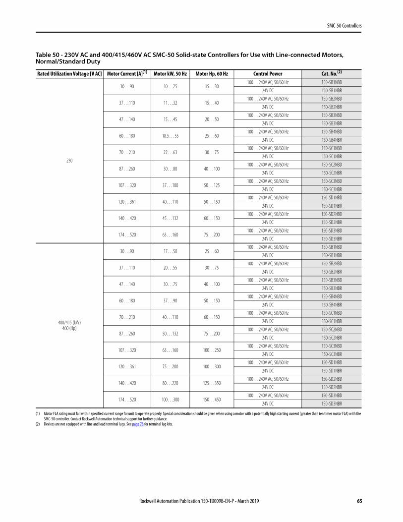
Table 50 - 230V AC and 400/415/460V AC SMC-50 Solid-state Controllers for Use with Line-connected Motors, Normal/Standard Duty
Rated Utilization Voltage [V AC] Motor Current [A](1)
(1) Motor FLA rating must fall within specified current range for unit to operate properly. Special consideration should be given when using a motor with a potentially high starting current (greater than ten times motor FLA) with the SMC-50 controller. Contact Rockwell Automation technical support for further guidance.
Motor kW, 50 Hz Motor Hp, 60 Hz Control Power Cat. No.(2)
(2) Devices are not equipped with line and load terminal lugs. See page 78 for terminal lug kits.
Rockwell Automation Publication 150-TD009B-EN-P - March 2019 65
SMC-50 Controllers
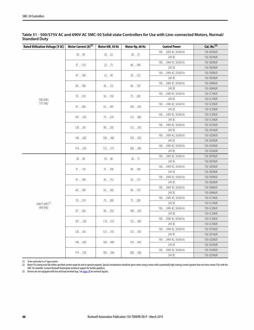
Table 51 - 500/575V AC and 690V AC SMC-50 Solid-state Controllers for Use with Line-connected Motors, Normal/Standard Duty
Rated Utilization Voltage [V AC] Motor Current [A](2)
(2) Motor FLA rating must fall within specified current range for unit to operate properly. Special consideration should be given when using a motor with a potentially high starting current (greater than ten times motor FLA) with the SMC-50 controller. Contact Rockwell Automation technical support for further guidance.
Motor kW, 50 Hz Motor Hp, 60 Hz Control Power Cat. No.(3)
(3) Devices are not equipped with line and load terminal lugs. See page 78 for terminal lug kits.
66 Rockwell Automation Publication 150-TD009B-EN-P - March 2019
SMC-50 Controllers
Heavy-duty Ratings (for centrifugal fans, crushers, mixers, long conveyors, etc.)
Utilization Category: AC-53a:3.5-30:99-1. Start Not to Exceed: 350% of the controller maximum current rating, 30 second start time, 99% ON load factor, one start per hour with 50 °C surrounding air ambient temperature.
• NOTE: See and use the SMC Estimation Wizard and SMC Thermal Estimation Wizard to confirm that the SMC controller selection meets the application requirements. See Sizing and Selection Tools for more information. For additional assistance, visit ab.rockwellautomation.com or contact Industrial Controls Technical Support by email at [email protected] or by phone at 440-646-5800.
Table 52 - 200/208V AC and 230V AC SMC-50 Solid-state Controllers for Use with Line-connected Motors, Heavy Duty
Rated Utilization Voltage [V AC] Motor Current [A](1)
(1) Motor FLA rating must fall within specified current range for unit to operate properly. Special consideration should be given when using a motor with a potentially high starting current (greater than ten times motor FLA) with the SMC-50 controller. Contact Rockwell Automation technical support for further guidance.
Motor kW, 50 Hz Motor Hp, 60 Hz Control Power Cat. No.(2)
(2) Devices are not equipped with line and load terminal lugs. See page 78 for terminal lug kits.
Table 53 - 400/415/460V AC and 500/575V AC SMC-50 Solid-state Controllers for Use with Line-connected Motors, Heavy Duty
Rated Utilization Voltage [V AC] Motor Current [A](1)
(1) Motor FLA rating must fall within specified current range for unit to operate properly. Special consideration should be given when using a motor with a potentially high starting current (greater than ten times motor FLA) with the SMC-50 controller. Contact Rockwell Automation technical support for further guidance.
Motor kW, 50 Hz Motor Hp, 60 Hz Control Power Cat. No.(2)
(2) Devices are not equipped with line and load terminal lugs. See page 78 for terminal lug kits.
68 Rockwell Automation Publication 150-TD009B-EN-P - March 2019
SMC-50 Controllers
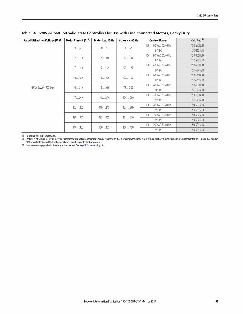
Table 54 - 690V AC SMC-50 Solid-state Controllers for Use with Line-connected Motors, Heavy Duty
Rated Utilization Voltage [V AC] Motor Current [A](2)
(2) Motor FLA rating must fall within specified current range for unit to operate properly. Special consideration should be given when using a motor with a potentially high starting current (greater than ten times motor FLA) with the SMC-50 controller. Contact Rockwell Automation technical support for further guidance.
Motor kW, 50 Hz Motor Hp, 60 Hz Control Power Cat. No.(3)
(3) Devices are not equipped with line and load terminal lugs. See page 78 for terminal lug kits.
Rockwell Automation Publication 150-TD009B-EN-P - March 2019 69
SMC-50 Controllers
For Use with Delta-connected Motors
Normal/Standard Duty Ratings (for pumps, compressors, elevators, and short conveyors)
Utilization Category: AC-53a:3.5-10:99-2. Start Not to Exceed: 350% of the controller maximum current rating, 10-second start time, 99% ON load factor, two starts per hour with 40 °C surrounding air ambient temperature.
• NOTE: See and use the SMC Estimation Wizard and SMC Thermal Estimation Wizard to confirm that the SMC controller selection meets the application requirements. See Sizing and Selection Tools for more information. For additional assistance, visit ab.rockwellautomation.com or contact Industrial Controls Technical Support by email at [email protected] or by phone at 440-646-5800.
Table 55 - 200/208V AC and 230V AC SMC-50 Solid-state Controllers for Use with Delta-connected Motors, Normal/Standard Duty
Rated Utilization Voltage [V AC] Motor Current [A](1)
(1) Motor FLA rating must fall within specified current range for unit to operate properly. Special consideration should be given when using a motor with a potentially high starting current (greater than ten times motor FLA) with the SMC-50 controller. Contact Rockwell Automation technical support for further guidance.
Motor kW, 50 Hz Motor Hp, 60 Hz Control Power Cat. No.(2)
(2) Devices are not equipped with line and load terminal lugs. See page 78 for terminal lug kits.
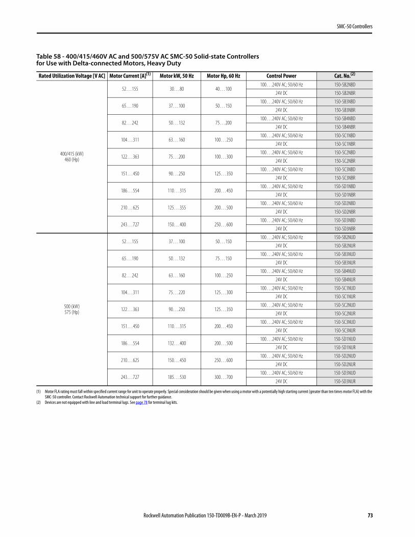
Table 56 - 400/415/460V AC and 500/575V AC SMC-50 Solid-state Controllers for Use with Delta-connected Motors, Normal/Standard Duty
Rated Utilization Voltage [V AC] Motor Current [A](1)
(1) Motor FLA rating must fall within specified current range for unit to operate properly. Special consideration should be given when using a motor with a potentially high starting current (greater than ten times motor FLA) with the SMC-50 controller. Contact Rockwell Automation technical support for further guidance.
Motor kW, 50 Hz Motor Hp, 60 Hz Control Power Cat. No.(2)
(2) Devices are not equipped with line and load terminal lugs. See page 78 for terminal lug kits.
Rockwell Automation Publication 150-TD009B-EN-P - March 2019 71
SMC-50 Controllers
Heavy-duty Ratings (for centrifugal fans, crushers, mixers, long conveyors, etc.)
Utilization Category: AC-53a:3.5-30:99-1. Start Not to Exceed: 350% of the controller maximum current rating, 30 second start time, 99% ON load factor, one start per hour with 50 °C surrounding air ambient temperature.
• NOTE: See and use the SMC Estimation Wizard and SMC Thermal Estimation Wizard to confirm that the SMC controller selection meets the application requirements. See Sizing and Selection Tools for more information. For additional assistance, visit ab.rockwellautomation.com or contact Industrial Controls Technical Support by email at [email protected] or by phone at 440-646-5800.
Table 57 - 200/208V AC and 230V AC SMC-50 Solid-state Controllers for Use with Delta-connected Motors, Heavy Duty
Rated Utilization Voltage [V AC] Motor Current [A](1)
(1) Motor FLA rating must fall within specified current range for unit to operate properly. Special consideration should be given when using a motor with a potentially high starting current (greater than ten times motor FLA) with the SMC-50 controller. Contact Rockwell Automation technical support for further guidance.
Motor kW, 50 Hz Motor Hp, 60 Hz Control Power Cat. No.(2)
(2) Devices are not equipped with line and load terminal lugs. See page 78 for terminal lug kits.
Table 58 - 400/415/460V AC and 500/575V AC SMC-50 Solid-state Controllers for Use with Delta-connected Motors, Heavy Duty
Rated Utilization Voltage [V AC] Motor Current [A](1)
(1) Motor FLA rating must fall within specified current range for unit to operate properly. Special consideration should be given when using a motor with a potentially high starting current (greater than ten times motor FLA) with the SMC-50 controller. Contact Rockwell Automation technical support for further guidance.
Motor kW, 50 Hz Motor Hp, 60 Hz Control Power Cat. No.(2)
(2) Devices are not equipped with line and load terminal lugs. See page 78 for terminal lug kits.
Rockwell Automation Publication 150-TD009B-EN-P - March 2019 73
SMC-50 Controllers
Typical Wiring Diagrams
Typical Power Wiring Diagrams
Figure 20 - Power Wiring Diagrams
(1) Contactor must be fully rated for motor Hp/kW and FLA.(2) For North American applications, size the contactor according to the motor Hp and FLA. For IEC applications, size the contactor according to the motor AC-1 or AC-3 rating. the short-circuit current rating
of the contactor must be similar to that of the SMC-50 controller.
T1 T2 T3
K1
L1 L2 L3
K1
L1 L2 L3
T4T5
L1 L2 L3
K1
T1 T2 T3T4 T5T6
L1 L2 L3
1 3 5
2 4 6
1 3 5
2 4 6W1U1
1 3 5
L1 L2 L3
1 3 5
2 4 61 3 5
2 4 6K1
W2
U2
V2
L1 L2 L3
1 3 5
1 3 52 4 6
2 4 6
1 3 5
4V
6W
2U
K1
V1
2 4 6W1U1 V1
2 4 6
W U V
K1
1 3 5
2 2 2
T1 T2 T3
T6
Diagrams per NEMA Symbology
SMC-50 solid-state controller
SMC-50 controller with internal bypass
SMC-50 solid-state controller
SMC-50 controller with internal bypass
Diagrams per IEC Symbology
SMC-50controller
SMC-50controller
SMC-50controller
SMC-50controller SMC-50
controller
SMC-50controller
Line connection with isolation contactor
(default mode)
Line connection with isolation contactor
(default mode)
Inside-the-Delta connection with isolation contactor
(optional mode)
Inside-the-Delta connection with isolation contactor
(optional mode)
Delta connection with shorted SCR protection
(optional mode)
Delta connection with shorted SCR protection
(optional mode)
Motor Motor Motor
3~Motor
3~Motor
3~Motor
(1) (1)
(2)
(1) (1)
(2)
74 Rockwell Automation Publication 150-TD009B-EN-P - March 2019
SMC-50 Controllers
Typical Control Wiring Diagrams
Figure 21 - For Standard 3-Wire Control—DC Inputs, No DPI Control
(1) Customer supplied.(2) See the controller nameplate to verify control power input ratings (100...240V AC or 24V DC).(3) Terminal 11 (In 1 DC) 24V DC input configured for START input using Parameter 56. (4) Terminal 10 (In 2 DC) 24V DC input configured for COAST, STOP option, etc. using Parameter 57.NOTE: The controller generates an I/O configuration fault if any input is configured for START or SLOW speed and no input is selected for COAST or STOP. (5) A customer-supplied jumper is required to enable standard I/O operation. (6) Due to current leakage through an SCR in the OFF state (controller stopped), some form of off-stream line power isolation is recommended if maintenance is required on the motor. See the Isolation
Contactor Applications diagram for details.NOTE: In addition to a small amount of leakage current flowing through an SCR in the off-state, failure of one or more solid-state power switching components allows uncontrolled current to flow to the
motor winding(s). This could potentially result in overheating or damage to the motor. To help prevent potential personal injury or equipment damage, the installation of an isolation contactor or shunt trip-type circuit breaker capable of interrupting the motor locked rotor current on the line side of the SMC-50 controller is recommended. Operation of the isolation device should be coordinated using one of the SMC-50 controller auxiliary contacts configured to NORMAL.
T1/2
T2/4
T3/6
L1/1
L2/3
L3/5
+L1-L2
12 11 10 9 8 7 6 5 4 3 2 1
(2)
Motor (1) (6)
SMC-50 Controller Circuit Protective Device
3-phase AC line power
(1)
Fast-acting SCR fuses (optional)
120V/240V AC Control Transformer with fuse or 120/240V AC Power Supply or24V DC Power Supply
(1)
(1)
(2)
(1)
(3) (4)
(5)
Control Power and Ground
Inte
rnal
+24
V DC
In2 D
C
Enab
le I/O
Inte
rnal
DC Co
mm
on
Aux 2 Aux 1
Control Module Standard I/O
Stop
Start
In1 D
C
(1)
Rockwell Automation Publication 150-TD009B-EN-P - March 2019 75
SMC-50 Controllers
Figure 22 - For 2-Wire Control with Stopping Capability—DC Inputs, No DPI Control
(1) Customer supplied. (2) See the controller nameplate to verify control power input ratings (100...240V AC or 24V DC).(3) Terminal 10 (In 2 DC) 24V DC N.O. input is configured for start/stop or start/coast using Parameter 57 (contact closed start initiated, contact open, stop initiated). When using start/stop or start/coast, a
N.O. input contact must be used. NOTE: The controller generates an I/O configuration fault if any input is configured for START or SLOW speed and no input is selected for COAST or STOP. (4) A customer-supplied jumper is required to enable controller standard I/O operation. (5) Due to current leakage through an SCR in the OFF state (controller stopped), some form of upstream line power isolation is recommended if maintenance is required on the motor. See the Isolation
Contactor Applications diagram for details. (6) Configure In1 (Input 1—Parameter 56) to "Disable".NOTE: In addition to a small amount of leakage current flowing through an SCR in the off-state, failure of one or more solid-state power switching components allows uncontrolled current to flow to the
motor winding(s). This could potentially result in overheating or damage to the motor. To help prevent potential personal injury or equipment damage, the installation of an isolation contactor or shunt trip-type circuit breaker capable of interrupting the motor’s locked rotor current on the line side of the SMC-50 controller is recommended. Operation of the isolation device should be coordinated using one of the SMC-50 controller Aux contacts configured to NORMAL.
T1/2
T2/4
T3/6
L1/1
L2/3
L3/5
+L1-L2
12 11 10 9 8 7 6 5 4 3 2 1
Motor (1) (5)
SMC-50 Controller Circuit Protective Device 3-phase AC line power
(1)
Fast-acting SCR fuses (optional)
(1)
(3)
Control Power and Ground
Inte
rnal
+24
V DC
In2 D
C
Enab
le I/O
Inte
rnal
DC Co
mm
on
Aux 2 Aux 1
Control Module Standard I/O
Start/Stop
In1 D
C
(1)
(2)
(2)(6)
(4)
120V/240V AC Control Transformer with fuse or 120/240V AC Power Supply or24V DC Power Supply
(1)
76 Rockwell Automation Publication 150-TD009B-EN-P - March 2019
SMC-50 Controllers
Accessories
Option Modules
Option modules can be used to add or expand the functionality of the SMC-50 Control Module. Option modules are installed into the control module's three expansion ports, 7 through 9.
• NOTE: If the application requires network communication, a Cat. No. 20-COMM-X communication adapter must be inserted in expansion port 9.
Converter Modules
DescriptionCompatible Control
Module Ports
Maximum No. of Option Modules of this Type
Per ControllerCat. No.
PTC, Ground Fault, and Current Feedback Option Module 7 and 8 1 150-SM2
Analog I/O Option Module: 2 analog inputs (voltage or current) and 2 analog outputs (voltage or current) 7, 8, 9 3 150-SM3
Digital I/O Option Module: 4 100…240V AC inputs and 3 relay outputs 7, 8, 9 3 150-SM4
Description For Use With Rated Current [A] Cat. No.
Three-Phase Current Monitoring ModuleUsed with a Cat. No. 150-SM2 to provide current feedback to
the SMC-50 controller when in external bypass configuration.(1)
(1) Requires user-supplied current transformers with 5 A secondary.
30…180 825-MCM180
181…520 825-MCM20
Connection Cable (replacement) Cat. No. 150-SM2 to Bul. 825-MCM connection All — 825-MCA
Core Balance Ground Fault Sensor Used with a Cat. No. 150-SM2 to provide ground current feedback.(2)
(2) The ground fault sensing feature of the SMC-50 controller is intended for monitoring purposes only. It is not to be used as a ground fault circuit interrupter for personnel protection as defined by Article 100 of the NEC. The sensing feature has not been evaluated to UL 1053.
Turns Ratio:100:1 825-CBCT
Rockwell Automation Publication 150-TD009B-EN-P - March 2019 77
SMC-50 Controllers
Protective Modules
The same protective module mounts on the line or load side of the SMC-50 controller. Use of protective modules is highly recommended. For applications that require both line and load side protection, you must order two protective modules.
• Note: You must not place protective modules on the load (motor) side of an SMC-50 controller when using an inside-the-delta connection or with pump, braking, or linear speed acceleration/deceleration control.
Terminal Lug Kits
Distribution Blocks
Current Rating Description Cat. No.
90...520108…480
480V protective module 150-F84L
600V protective module 150-F86L
For Use With Controller TypeCurrent
Range [A]Wire Size Range
Total No. of Terminal Lugs Possible Each Side Pkg. Qty. Cat. No.
Description100…240V AC Control Voltage 24V DC Control Voltage
Cat. No. Cat. No.
Frame 3 Power Structure Assembly • Contains all three power poles in one package and includes the pole-to-
control module transition cover and cooling fan.
108 A, 200…480V AC line 150-SPP108BD 150-SPP108BR (1)
(1) Consult your local Rockwell Automation sales office or Allen-Bradley distributor for availability.
135 A, 200…480V AC line 150-SPP135BD 150-SPP135BR(1)
108 A, 200…690V AC line 150-SPP108UD 150-SPP108UR(1)
135 A, 200…690V AC line 150-SPP135UD 150-SPP135UR(1)
Frame 4 Power Pole• Contains one power pole
201 A, 200…480V AC line 150-SPP201B
251 A, 200…480V AC line 150-SPP251B
201 A, 200…690V AC line 150-SPP201U
251 A, 200…690V AC line 150-SPP251U
Frame 5 Power Pole• Contains one power pole
317 A, 200…480V AC line 150-SPP317B
361 A, 200…480V AC line 150-SPP361B
480 A, 200…480V AC line 150-SPP480B
317 A, 200…690V AC line 150-SPP317U
361 A, 200…690V AC line 150-SPP361U
480 A, 200…690V AC line 150-SPP480U
Base Plate• for mounting power poles
201…251 A 41391-803-01
317…480 A 41391-803-02
Description Rated Control Voltage For Use With Cat. No.
Replacement Fan
for SMC-50 Frame 3 controllers100…240V AC
150-S108…-S135150-SRF135D
24V DC 150-SRF135R(1)
(1) Consult your local Rockwell Automation sales office or Allen-Bradley distributor for availability.
for SMC-50 Frame 4 controllers100…240V AC
150-S201…-S251150-SRF251D
24V DC 150-SRF251R(1)
for SMC-50 Frame 5 controllers100…240V AC
150-S317…-S480150-SRF480D
24V DC 150-SRF480R(1)
Description Rated Current [A] Line Voltage [V AC] Control Voltage Cat. No.
SMC-50 with Bypass Replacement Controller Cover
201
200…480100…240V AC 150-S201RCBD
24V DC(1)
(1) 24V DC Control Inputs ONLY. Not compatible with 24V AC Control Inputs.
150-S201RCBR(2)
(2) Consult your local Rockwell Automation sales office or Allen-Bradley distributor for availability.
200…690100…240V AC 150-S201RCUD
24V DC(1) 150-S201RCUR(2)
251
200…480100…240V AC 150-S251RCBD
24V DC(1) 150-S251RCBR(2)
200…690100…240V AC 150-S251RCUD
24V DC(1) 150-S251RCUR(2)
317
200…480100…240V AC 150-S317RCBD
24V DC(1) 150-S317RCBR(2)
200…690100…240V AC 150-S317RCUD
24V DC(1) 150-S317RCUR(2)
361
200…480100…240V AC 150-S361RCBD
24V DC(1) 150-S361RCBR(2)
200…690100…240V AC 150-S361RCUD
24V DC(1) 150-S361RCUR(2)
480
200…480100…240V AC 150-S480RCBD
24V DC(1) 150-S480RCBR(2)
200…690100…240V AC 150-S480RCUD
24V DC(1) 150-S480RCUR(2)
Rockwell Automation Publication 150-TD009B-EN-P - March 2019 81
SMC-50 Controllers
For Solid-state Units
Description100…240V AC Control Voltage 24V DC Control Voltage
Cat. No. Cat. No.
Frame B Power Structure Assembly • Contains all three power poles in one package and includes the pole-to-control
module transition cover and cooling fan
90 A, 200…480V AC line 150-SPPB1B 150-SPPB1BR
110 A, 200…480V AC line 150-SPPB2B 150-SPPB2BR
140 A, 200…480V AC line 150-SPPB3B 150-SPPB3BR
180 A, 200…480V AC line 150-SPPB4B 150-SPPB4BR
90 A, 200…690V AC line 150-SPPB1U 150-SPPB1UR
110 A, 200…690V AC line 150-SPPB2U 150-SPPB2UR
140 A, 200…690V AC line 150-SPPB3U 150-SPPB3UR
180 A, 200…690V AC line 150-SPPB4U 150-SPPB4UR
Frame C Power Pole• Contains one power pole — SCR, heatsink assembly, and cable
210 A, 200…480V AC line 150-SPPC1B
260 A, 200…480V AC line 150-SPPC2B
320 A, 200…480V AC line 150-SPPC3B
210 A, 200…690V AC line 150-SPPC1U
260 A, 200…690V AC line 150-SPPC2U
320 A, 200…690V AC line 150-SPPC3U
Frame D Power Pole• Contains one power pole — SCR, heatsink assembly, and cable
361 A, 200…480V AC line 150-SPPD1B
420 A, 200…480V AC line 150-SPPD2B
520 A, 200…480V AC line 150-SPPD3B
361 A, 200…690V AC line 150-SPPD1U
420 A, 200…690V AC line 150-SPPD2U
520 A, 200…690V AC line 150-SPPD3U
Description Cat. No.
Replacement Cover Replacement controller cover210…320 A units 150-SCRC
361…520 A units 150-SDRC
Description Rated Control Voltage For Use With Cat. No.
Replacement Fan
for SMC-50 Frame B controllers100…240V AC
150-SB units (90…180 A)150-SF1
24V DC 150-SF1R
for SMC-50 Frame C controllers100…240V AC
150-SC units (210…320 A)150-SF2D
24V DC 150-SF2R
for SMC-50 Frame D controllers100…240V AC
150-SD units (361…520 A)150-SF3D
24V DC 150-SF3R
Replacement Fan Cover
fan cover for SMC-50 Frame B controllers — 150-SB units (90…180 A) 150-SBFC
fan cover for SMC-50 Frame C controllers — 150-SC units (210…320 A) 150-SCFC
fan cover for SMC-50 Frame D controllers — 150-SD units (361…520 A) 150-SDFC
82 Rockwell Automation Publication 150-TD009B-EN-P - March 2019
SMC-50 Controllers
Upgrade Kits
These kits allow you to upgrade from SMC Flex controllers to SMC-50 controllers with internal bypass. Kits contain SMC-50 control module, programming device, optional I/O card (if needed), and plastic mounting/transition cover (if needed).
• Important: Carefully check current range, line voltage, and control input voltage when selecting an upgrade kit. Not all control voltages or current ranges can be upgraded.
Description Kit Contents(1)
(1) Kit contains one of each catalog number listed.
Rated Current [A] Line Voltage [V AC] Control Voltage(2)
(2) The SMC-50 control module provides two (2) 24V DC control inputs. If you need additional inputs, you must use 100…240V AC inputs (requires 150-SM4 option module).
Cat. No.
Frame 3 SMC Flex to SMC-50 controllers with bypass upgrade kit
• 150-SCMD control module• 150-SM4 digital I/O module• 20-HIM-A6 LCD HIM
108200…690 100…240V AC
150-S108UPGD
135 150-S135UPGD
• 150-SCMR control module• 20-HIM-A6 LCD HIM
108200…690 24V DC(3)
(3) 24V DC control voltage ONLY. Not compatible with 24V AC control voltage.
150-S108UPGR (4)
(4) Consult your local Rockwell Automation sales office or Allen-Bradley distributor for availability.
135 150-S135UPGR(4)
Frame 4 SMC Flex to SMC-50 controllers with bypass upgrade kit
• 150-SCMD control module• 150-SM4 digital I/O module• 20-HIM-A6 LCD HIM• Plastic mounting/transition cover
201
200…480
100…240V AC
150-S201UPGBD
200…575 150-S201UPGCD
200…690 150-S201UPGUD
251
200…480 150-S251UPGBD
200…575 150-S251UPGCD
200…690 150-S251UPGUD
• 150-SCMR control module• 20-HIM-A6 LCD HIM• Plastic mounting/transition cover
201
200…480
24V DC(3)
150-S201UPGBR(4)
200…575 150-S201UPGCR (4)
200…690 150-S201UPGUR (4)
251
200…480 150-S251UPGBR(4)
200…575 150-S251UPGCR(4)
200…690 150-S251UPGUR (4)
Rockwell Automation Publication 150-TD009B-EN-P - March 2019 83
SMC-50 Controllers
Specifications Table 59 - Functional Design
Electrical RatingsTable 60 - Power Circuit Ratings
Standard Features Description
InstallationPower Wiring standard squirrel-cage induction motor or a Wye-Delta, six-lead motor
Control Wiring 2- and 3-wire control for a wide variety of applications
Configuration/Setup(1)
(1) The configuration method must be ordered separately from the controller, which does not include a setup tool.
Keypad Cat. No. 20-HIM-A6 full numeric keypad with LCD displayCat. No. 20-HIM-C6S remote panel mount full numeric keypad with LCD display
Software parameter values are downloaded to the SMC-50 with the Connected Components Workbench, DriveTools, and DriveExplorer programming software packages
Parameter Configuration Option Module (PCM) Cat. No. 150-SM6 provides simple and limited configuration by DIP and rotary dial switches
Communications four DPI ports for local serial communications. Network communication supported by optional 20- COMM-X modules
Starting and Stopping Modes modes include: Soft Start, Coast-to-Stop, Soft Stop, Current Limit Start, Dual Ramp, Full Voltage, Linear Speed Acceleration (start), Linear Speed Deceleration (stop), Torque Start, and Preset Slow Speed
Pump Control Start and Stop helps reduce fluid surges in centrifugal pumping systems during the starting and stopping period
Braking Control(2)
(2) Not intended to be used as an emergency stop. See the applicable standards for emergency stop requirements.
SMB Smart Motor Braking provides motor braking without additional equipment for applications that require the motor to stop quickly
Accu-Stop(5)
(5) Accu-Stop is not included as a parameter/function like that of the SMC-Flex. However, the Accu-Stop function can be accomplished with the SMB mode and Slow Speed with Braking functions.
provides controlled position stopping; during stopping, brake torque is applied to the motor until the motor reaches the preset slow speed and holds the motor at this speed until a stop command is given - braking torque is then applied until the motor reaches zero speed - braking current
is programmable
Slow Speed with Braking used on applications that require slow speed (in the forward or reverse direction) for positioning or alignment and requires braking control to stop
External Braking activates the external braking device by using aux. relay output
Protection and Diagnostics(3)
(3) Diagnostic indication depends on the type of configuration tool used. The standard LED status indication displays: Inhibit (stop enabled), Fault (non- resettable), Fault (resettable). For full local access, a HIM or personal computer software is required. For network access, full access to data can also be obtained.
displays: Power Loss, Line Fault, Voltage Unbalance, Excessive Starts/Hour, Phase Reversal, Undervoltage, Overvoltage, Controller Temperature, Stall, Jam, Open Gate, Overload, Underload, and Communication Fault
Metering Indication(4)
(4) Metering Indication depends on the type of configuration tool being used. Metering Indication requires the use of a HIM or a personal computer software configuration tool for full local access. Full access to data can also be obtained via network.
provides: Phase Current, Current Average, Phase-to-Phase Voltage, Voltage P-P Average, Phase-to-neutral Voltage, Calculated Torque, Real Phase Power, Real Power, Real Energy, Real Demand, Max Real Demand, Reactive Power, Reactive Energy + and -, Reactive Energy, Reactive Demand, Max Reactive Demand, Apparent Power, Apparent Energy, Apparent Demand, Number of Periods, Power Factor, Energy Savings, Elapsed Time 1 and 2, Running Time, Motor Speed, Start Time 1-5, Peak Current 1-5, Total Starts, THD V, THD I, THD V Average, THD I Average, Line Frequency,
Current Imbalance, and Voltage Unbalance
LED Status Indication by Multi-color (standard) displays fault and alarm codes: Running - with alarm, Running - no alarm, Ready - with alarm, Ready - no alarm, Ready - tuning enabled on next start, and Firmware Download Active - with alarm
Auxiliary Contacts (two standard) two fully programmable contacts as: normal, UTS, fault, alarm, external brake, auxiliary control, network, external bypass, or fan control
Description Device Rating UL/CSA/NEMA IEC
Rated Operation Voltage480V 200…480V AC (–15%, +10%) 200…415V (-15%, +10%)
690V 200…600V AC (–15%, +10%) 200…690V/Y (–15%, +10%)
Rated Insulation Voltage480V — 500V
690V — 690V
Rated Impulse Voltage480V — 6000V
690V — 6000V
Dielectric Withstand480V 2200V AC 2500V
690V 2200V AC 2500V
Repetitive Peak Inverse Voltage Rating480V 1400V 1400V
690V 1800V 1800V
Operating Frequency All 47...63 Hz 47...63 Hz
84 Rockwell Automation Publication 150-TD009B-EN-P - March 2019
SMC-50 Controllers
Table 61 - Utilization Category
Table 62 - Control Power Specifications
Perchlorate material – special handling may apply. See www.dtsc.ca.gov/hazardouswaste/perchlorate.This perchlorate warning only applies to primary Lithium Manganese Dioxide (LiMnO2) cells or batteries, and products containing these cells or batteries, sold or distributed in California, USA.
Solid-state90…520 A IP00 (IP20 - Control Terminals only)
90…180 A IP2X (with Optional Terminal Cover)
DV/DT Protection480V
RC Snubber Network690V
Transient Protection480...600V Metal Oxide Varistors: 220 Joules
690V None
Description UL/CSA/NEMA IECRated Operational Voltage 100…240V AC (-15%…+10%) or 24V DC (-10%…+10%)
Rated Insulation Voltage — 240V
Rated Impulse Voltage — 3000V
Dielectric Withstand 1500V AC 1500V
Operating Frequency 47…63 Hz or DC
Control Power Ride Through 22 ms
Max. Output of 24V DC Supply (Terminals 8 and 12) 300 mA
Control Module Battery Type CR 2032
This product contains a sealed lithium battery that may need to be replaced during the life of the product.At the end of its life, the battery contained in this product should be collected separately from any unsorted municipal waste.The collection and recycling of batteries helps protect the environment and contributes to the conservation of natural resources as valuable materials are recovered.
ATTENTION: There is a danger of explosion if the lithium battery or real-time clock module in this product is incorrectly replaced. Do not replace the battery or real-time clock module unless power has been removed and the area is known to be nonhazardous. Replace the battery only with catalog number 2711P-RY2032 or an equivalent CR2032 coin-cell battery.Do not dispose of the lithium battery or real-time clock module in a fire or incinerator. Dispose of used batteries in accordance with local regulations.For safety information on the handling of lithium batteries, including handling and disposal of leaking batteries, see Guidelines for Handling Lithium Batteries, publication AG 5-4.
Rockwell Automation Publication 150-TD009B-EN-P - March 2019 85
Table 75 - Integrated Bypass SCPD Performance, 690V Maximum, Type 1, Line Connected Motors Only
SCPD Performance(1)
(1) Consult local codes for proper sizing of short-circuit protection.
Type 1 Ratings(2)
(2) Basic Requirements for Type 1 Coordination: Under the short-circuit condition, the starter shall cause no danger to persons or to the installation. The starter may not be suitable for further service without repair or replacement of parts. For further details, refer to UL 508/CSA C22.2 No. 14 and EN 60947-4-2.
Motor Connection Type
Cat. NoCurrent
Rating [A]
Non-time Delay Fuse(3)
(3) Non-Time Delay Fuses: Class K5 up to 600 A, Class L above 600 A.
Inverse Time (Thermal Magnetic) Circuit BreakerMax. Standard Available Fault
[kA]Max. Current [A]
Max. Standard Available Fault [kA]
Max. Current [A]
Line
150-S108N… 10810
40010
300
150-S135N… 135 500 400
150-S201N… 20118
60018
600
150-S251N… 251 700 700
150-S317N… 31730
80030
800
150-S361N… 361 1000 1000
150-S480N… 480 42 1200 42 1200
Inside Delta
150-S108N… 18710
60010
500
150-S135N… 234 700 700
150-S201N… 34818
100018
1000
150-S251N… 435 1200 1200
150-S317N… 54930
160030
1600
150-S361N… 625 1600 1600
150-S480N… 831 42 1600 42 1200
SCPD Performance(1)
(1) Consult local codes for proper sizing of short-circuit protection.
Type 1 Ratings(2)
(2) Basic Requirements for Type 1 Coordination: Under the short-circuit condition, the starter shall cause no danger to persons or to the installation. The starter may not be suitable for further service without repair or replacement of parts. For further details, refer to UL 508/CSA C22.2 No. 14 and EN 60947-4-2.
Motor Connection Type Cat. NoCurrent
Rating [A]Max. Standard
Available Fault [kA]Max. Ampere Tested — North
American StyleMax. Ampere Tested — European
Style
Line
150-S108N… 108
70
A070URD33xxx500 6,9 gRB 73xxx4006,6URD33xxx500
150-S135N… 135 A070URD33xxx500 6,9 gRB 73xxx4006,6URD33xxx500
150-S201N… 201 A070URD33xxx700 6,9 gRB 73xxx6306,6URD33xxx700
150-S251N… 251 A070URD33xxx700 6,9 gRB 73xxx6306,6URD33xxx700
150-S317N… 317 A070URD33xxx900 6,9 gRB 73xxx8006,6URD33xxx900
150-S361N… 361 A070URD33xxx900 6,9 gRB 73xxx8006,6URD33xxx900
150-S480N… 480 A070D33xxx1250A100URD73xxx1250
9 URD 73xxx12506,6URD33xxx1250
Rockwell Automation Publication 150-TD009B-EN-P - March 2019 89
SMC-50 Controllers
Table 76 - Integrated Bypass SCPD Performance, High Fault, Type 1
(1) Consult local codes for proper sizing of short-circuit protection.
Type 1 Ratings(2)
(2) Basic Requirements for Type 1 Coordination: Under the short-circuit condition, the starter shall cause no danger to persons or to the installation. The starter may not be suitable for further service without repair or replacement of parts. For further details, refer to UL 508/CSA C22.2 No. 14 and EN 60947-4-2.
Motor Connection Type Cat. NoCurrent
Rating [A]
Class J or Class L Fuse(3)
(3) High Capacity fault ratings when used with time delay Class J or time delay Class L fuse.
Inverse Time (Thermal Magnetic) Circuit Breaker(4)
480V, 65kA Maximum
(4) Circuit Breaker must be of the designated 140G Frame.
(1) Consult local codes for proper sizing of short-circuit protection.
Cat. No.Current Rating [A]
I2t Reference (103A2s)
North America(4) (5)
(4) Calculated only, NOT tested.(5) Fuse size based on a start profile of 300% of the controller maximum current rating for 50 seconds. Contact Technical Support at [email protected] or 440-646-5800 for applications with a longer start time or
higher starting current.
European(4) (5)
Line(2)
(2) For line-connected motors, connect fuses to the SMC-50 in line with three-phase power terminals L1, L2, and L3.
Inside Delta(3)
(3) For delta-connected motors, connect fuses to the SMC-50 inside the delta after terminals L1-T6, L2-T4, and L3-T5.
Max. Available Fault (480V) [kA]
Ferraz-shawmut Fuse Part No.
Max. Available Fault (500V) [kA]
Ferraz-shawmut Fuse Part No.
150-S108N… 108 187 87
65
A70QS200
50
6,9URD31*0250
150-S135N… 135 234 90 A70QS200 6,9URD31*0250
150-S201N… 201 348 200 A70QS400 6,9URD32*0450
150-S251N… 251 435 238 A70QS400 6,9URD32*0450
150-S317N… 317 549 300 A70QS450 6,9URD33*0550
150-S361N… 361 625 320 A70QS450 6,9URD33*0550
150-S480N… 480 831 1200 A70QS700 65 6,9URD32*0700
90 Rockwell Automation Publication 150-TD009B-EN-P - March 2019
(1) Consult local codes for proper sizing of short-circuit protection.
Type 1 Ratings(4)
(4) Basic Requirements for Type 1 Coordination: Under the short-circuit condition, the starter shall cause no danger to persons or to the installation. The starter may not be suitable for further service without repair or replacement of parts. For further details, refer to UL 508/CSA C22.2 No. 14 and EN 60947-4-2.
Motor Connection
TypeCat. No
Current Rating [A]
Non-time Delay Fuse(5)
(5) Non-Time Delay Fuses: Class K5 up to 600 A, Class L above 600 A.
Time Delay Fuse(7)
(7) Time Delay Fuse: Devices rated 90…180 A (155…311 A): Class RK5. Devices rated 210…520 A (363…900 A): Class RK5 or Class J up to 600 A, Class L above 600 A.
Inverse Time (Thermal Magnetic) Circuit Breaker
Max. Standard Available Fault
[kA]
Typical Current
[A]
Max. Current
[A]
Max. Standard Available Fault
[kA]
Typical Current
[A]
Max. Current
[A]
Max. Standard Available Fault
[kA]
Typical Current
[A]
Max. Current
[A]
Line(2)
(2) UL/CSA (Type 1) and EN 60947-4-2 (Type 1) for Line-Connected Motors: Suitable for use on a circuit capable of delivering not more than the listed max. RMS symmetrical amperes (UL: 600V maximum, IEC: 690V max.).
150-SB1N… 90
10
250 350
10
150 200
10
225 350
150-SB2N… 110 300 400 175 225 250 300
150-SB3N… 140 400 500 225 300 350 400
150-SB4N… 180 500 500 300 400 450 500
150-SC1N… 210
18
600 600
18
350 450
18
500 600
150-SC2N… 260 700 700 450 500 600 700
150-SC3N… 320 800 800 500 700 800 800
150-SD1N… 361
30/18(6)
(6) UL/CSA applications = 30 kA, 600V maximum. IEC applications = 18 kA, 690V maximum.
1000 1000
30/18(6)600 800
30/18(6)800 1000
150-SD2N… 420 1200 1200 700 800 1000 1200
150-SD3N… 520 1200 1200 800 1000 1200 1200
Inside Delta(3)
(3) UL/CSA (Type 1) and EN 60947-4-2 (Type 1) for Inside-the-Delta Connected Motors: Suitable for use on a circuit capable of delivering not more than the listed max. RMS symmetrical amperes (UL and IEC: 600V maximum).
150-SB1N… 155
18
450 450
18
250 300
18
350 450
150-SB2N… 190 500 500 300 400 450 500
150-SB3N… 242 700 700 400 500 600 700
150-SB4N… 311 800 800 500 600 700 800
150-SC1N… 363
30
1000 1000
30
600 800
30
800 1000
150-SC2N… 450 1200 1200 700 1000 1000 1200
150-SC3N… 554 1600 1600 800 1200 1200 1600
150-SD1N… 625
42
1600 1600
42
1000 1200
42
1200 1600
150-SD2N… 727 2000 2000 1200 1600 1600 2000
150-SD3N… 900 2500 2500 1200 2000 2000 2500
Rockwell Automation Publication 150-TD009B-EN-P - March 2019 91
SMC-50 Controllers
Table 79 - Solid-state SCPD Performance, High Fault, Type 1
(1) Consult local codes for proper sizing of short-circuit protection.
Type 1 Ratings(2)
(2) Basic Requirements for Type 1 Coordination: Under the short-circuit condition, the starter shall cause no danger to persons or to the installation. The starter may not be suitable for further service without repair or replacement of parts. For further details, refer to UL 508/CSA C22.2 No. 14 and EN 60947-4-2.
Motor Connection Type
Cat. NoCurrent
Rating [A]
Class J or Class L Fuse(3)
(3) High Capacity fault ratings when used with time delay Class J or time delay Class L fuse.
Inverse Time (Thermal Magnetic) Circuit Breaker480V, 65 kA Maximum
(1) Consult local codes for proper sizing of short-circuit protection.
Cat. No.
Current Rating [A]
I2t Reference (103A2s)
North America(4) (5)
(4) Calculated only, NOT tested.(5) Fuse size based on a start profile of 350% of the controller maximum current rating for 10 seconds. Contact Technical Support at [email protected] or 440-646-5800 for applications with a longer start time or
higher starting current.
Type 2 Coordination Per EN 60947-4-2(5) (6)
(6) Basic Requirements for Type 2 Coordination: Per EN 60947-4-2 under short-circuit conditions, the device shall cause no danger to persons or installation and shall be suitable for further use.
Line(2)
(2) For line-connected motors, connect fuses to the SMC-50 in line with three-phase power terminals T6, T4, and T5.
Inside Delta(3)
(3) For delta-connected motors, connect fuses to the SMC-50 inside the delta after terminals L1-T6, L2-T4, and L3-T5.
Max. Available Fault (480V) [kA]
Ferraz-shawmut
Fuse Part No.
Max. Available Fault (500V) [kA]
Ferraz-shawmut Fuse Part No.
150-SB1N… 90 155 92
65
A70QS150
65
6,9URD30*0200
150-SB2N… 110 190 95 A70QS175 6,9URD30*0200
150-SB3N… 140 242 100 A70QS200 6,9URD30*0250
150-SB4N… 180 311 106 A70QS250 6,9URD31*0315
150-SC1N… 210 363 200 A70QS350 6,9URD30*0315
150-SC2N… 260 450 238 A70QS400 6,9URD31*0400
150-SC3N… 320 554 320 A70QS450 6,9URD31*0450
150-SD1N… 361 625 1000 A70QS500 6,9URD31*0500
150-SD2N… 420 727 1100 A70QS600 6,9URD31*0630
150-SD3N… 520 900 1200 A70QS700 6,9URD31*0700
92 Rockwell Automation Publication 150-TD009B-EN-P - March 2019
SMC-50 Controllers
Environmental, Mechanical, and Other RatingsTable 81 - Environmental Ratings
Operating Ambient Temperature Range (surrounding air ambient)
Integrated Bypass Devices-20…+50 °C (-4…+122 °F) (no derating) —
For operation 50...65 °C (122...149 °F), refer to Thermal Wizard.-20…+40 °C (-4…104 °F) (Enclosed)
Solid-state Devices-20…+40 °C (-4…+104 °F) (no derating) —
For operation 40...65 °C (104...149 °F), refer to Thermal Wizard.-20…+40 °C (-4…104 °F) (Enclosed)
Storage and Transportation Temperature Range –25…+75 °C (-13…+167 °F)
Altitude 2000 m (6560 ft) without derating; for operation above 2000...7000 m (6560...22965 ft) maximum, refer to Thermal Wizard
Humidity 5…95% (noncondensing)
Pollution Degree 2
Mounting Orientation Vertical
Atmospheric Protection ANSI/ISA - 71.04-2013; Class G3 Environment
Attribute Rating
Resistance to VibrationOperational
All Devices1.0 G Peak, 0.15 mm (0.006 in.) Displacement
Non-Operational 2.5 G Peak, 0.38 mm (0.015 in.) Displacement
Resistance to Shock
Integrated BypassOperational
108…480 A5.5 G
Non-Operational 25 G
Solid-stateOperational
90...520 A15 G
Non-Operational 30 G
Construction
Power Poles Heatsink Hockey Puck Thyristor Modular Design
Control Modules Thermoset and Thermoplastic Moldings
Metal Parts Plated Brass, Copper, or Steel
Terminals
Power Terminal Lugs
Integrated Bypass
108…135 A One M10 x 1.5 diameter hole per power pole
201…251 A Two M10 x 1.5 diameter hole per power pole
317…480 A Two M12 x 1.75 diameter hole per power pole
Solid-state
90…180 A One 10.5 mm (0.41 in.) diameter hole per power pole
210…320 A Two 10.5 mm (0.41 in.) diameter holes per power pole
361…520 A Two 13.5 mm (0.53 in.) diameter holes per power pole
Power Terminal Markings NEMA, CENELEC EN50 012
Control Terminals M3 Screw Clamp Clamping Yoke Connection
Attribute Rating
EMC Emission LevelsConducted Radio Frequency Emissions Class A (per EN 60947-4-2)
Radiated Emissions Class A (per EN 60947-4-2)
EMC Immunity Levels
Electrostatic Discharge 8 kV Air Discharge Per EN 60947-4-2
Radio Frequency Electromagnetic Field Per EN 60947-4-2
Fast Transient Per EN 60947-4-2
Surge Transient Per EN 60947-4-2
Rockwell Automation Publication 150-TD009B-EN-P - March 2019 93
SMC-50 Controllers
Table 84 - Overload Characteristics
Table 85 - Standards Compliance and Certifications
Overload Characteristics Device Type Rated Current [A] Line-connected Devices Delta-connected Devices
Current Range
Integrated Bypass Devices
108 27…108 47…187
135 34…135 59…234
201 67…201 116…348
251 84…251 145…435
317 106…317 183…549
361 120…361 208…625
480 160…480 277…831
Solid-state Devices
90 30…90 52…155
110 37…110 65…190
140 47…140 82…242
180 60…180 104…311
210 70…210 122…363
260 87…260 151…450
320 107…320 186…554
361 120…361 210…625
420 140…420 243…727
520 174…520 302…900
Overload Type Electronic - using I2t algorithm
Trip Classes 5 to 30
Trip Current Rating 118% of Motor FLC
Number of Poles 3
Standards Compliance Certifications
UL 508 c-UL-us Listed (Open Type) (File No. E96956)
EN 60947-4-2 CE Marked per EMC Directive and Low Voltage Directive
CCC(1)
(1) For updated certification status of controllers with 24V DC control power, consult your local Rockwell Automation sales office or Allen-Bradley distributor, or www.rockwellautomation.com/global/certification/overview.page.
C-Tick(1)
EAC(1)
KCC(1)
ABS(1)
94 Rockwell Automation Publication 150-TD009B-EN-P - March 2019
(2) Circuit Breaker must be of the designated 140G Frame size for high fault short circuit ratings.
[A] 350 300 400 400 600 700 800 1000 1200 1200
Bul. 140G MCCB Frame Size K M N
Branch Protection Reference(1)
Inverse Time Circuit Breaker Selections(5)
35 kA at 600V Maximum 140G- K6F3-D 140G- K6F3-D 140G- K6F3-D 140G- M6F3-D 140G- M6F3-D 140G- M6F3-D 140G- M6F3-D — — —
50 kA at 600V Maximum — — — — — — — 140G- N6H3-E(6)
(6) Requires rating plug selection based on application; see the product directory: www.ab.rockwellautomation.com.
140G- N6H3-E12
140G- N6H3-E12
65 kA at 480V Maximum(2) 140G-K6F3-D 140G-K6F3-D 140G-K6F3-D 140G-K6F3-D 140G-M6F3-D 140G-M6F3-D 140G-M6F3-D 140G- N6H3-E12(6)
140G- N6H3-E12
140G- N6H3-E12
Fused Disconnect Selections, For Use With Non-Time Delay Fuses
194R-J200-1753
194R-J400-1753
194R-J400-1753
194R-J400-1753
194R-J600-1753
194R-J600-1753
194R-L800-1753 — — —
Bypass Contactor Reference(2) (3)
(3) For the most up-to-date information, including voltage ratings other than 600V, see the Global SCCR Tables at www.rockwellautomation.com.
AC-3 Rated per UL/CSA(4), Standard Fault SCCR
(4) In IEC regulated regions when sizing the bypass contactor per AC-1 or AC-3 ratings, the short circuit rating of the bypass contactor must be similar to that of the SMC-50 controller.
(2) Circuit Breaker must be of the designated 140G Frame size for high fault short circuit ratings. Other circuit breakers pending.
[A] 450 500 700 700 1000 1200 1200 — — —
Bul. 140G MCCB Frame Size M N Pending
Branch Protection Reference(1)
Inverse Time Circuit Breaker Selections(5)
35 kA at 600V Maximum 140G- K6F3-D 140G- M6F3-D
140G- M6F3-D
140G- M6F3-D — — — — — —
50 kA at 600V Maximum — — — — 140G- N6H3-E(6)
(6) Requires rating plug selection based on application; see the product directory: www.ab.rockwellautomation.com.
140G-N6H3-E12
140G-R12I3-E(6)
140G-R12I3-E(6)
140G- R12I3-E20
140G- R12I3-E25
65 kA at 480V Maximum(2) 140G-M6F3-D 140G-M6F3-D 140G-M6F3-D 140G-M6F3-D 140G- N6H3-E(6)
140G- N6H3-E12
140G- N6H3-E12 Pending
Fused Disconnect Selections, For Use With Non-Time Delay Fuses
194R-J400-1753
194R-J400-1753
194R-J600-1753
194R-J600-1753
194R-L800-1753 — — — — —
Bypass Contactor Reference(1) (3)
(3) For the most up-to-date information, including voltage ratings other than 600V, see the Global SCCR Tables at www.rockwellautomation.com.
AC-3 Rated per UL/CSA(4), Standard Fault SCCR
(4) In IEC regulated regions when sizing the bypass contactor per AC-1 or AC-3 ratings, the short circuit rating of the bypass contactor must be similar to that of the SMC-50 controller.
Dimensions are in inches (mm) unless otherwise noted. Dimensions are not to be used for manufacturing purposes.Table 90 - SMC-50 Controller Enclosure Requirements
The guidelines in Table 91 result from the open design of the SMC-50 controller and the minimum clearance requirements of 150 mm (6 in.) above and below the controller.Table 91 - SMC-50 Controller Minimum Enclosure Size
Enclosure RatingsStandard Device Rating: IP00 (NEMA Open Type)
Minimum Required Enclosure: IP23 (NEMA Type 1)
Recommended Enclosure:(1)
(1) See Table 91 for minimum enclosure size.
IP54 (NEMA Type 12)
Ambient temperature range (open air) or internal enclosure temperature range without derating:
Internal Bypass -20…+50 °C (-4…+122 °F)
Solid-state -20...40 °C (-4...104 °F)
Orientation and ClearanceMounting Orientation: Vertical ONLY
Minimum Clearance:Horizontal 0 cm (0 in.)
Vertical 15 cm (6 in.)
SMC-50 Controller with Internal Bypass
Catalog Numbermm (in.)(1)
(1) Actual enclosure size changes based on heat dissipation, duty cycle, ambient temperature, and external cooling. See the user manual, publication 150-UM011, for more information.
Figure 23 - 108/135 A Controller with Internal Bypass: Without Terminal Covers
• Note: When mounted in an enclosure, maintain a minimum of 6.0 inches (152.4 mm) clearance above and below the SMC-50 controller. Side-to-side clearance is not required.
6.56(166.6)
4.25(108)
2.13(54)
2.13(54)
15.31(388.9)
14.45(367)
17.47(443.7)
5.10(129.5)
1.56(39.5)
5.10(129.5)
0.30(7.5)
1.54(39)
1.25(31.8)
0.79(20.2)
0.49(12.5)
1.02(26)
16.57(420.8)
15.06(382.5)
14.07(357.5)
15.58(395.8)
.51(12.9)
0.19(4.8)
7.74(196.6)
6.25(158.9)
5.73(145.5)
8.56(217.3)
0.32(8)
See detail A
Detail ASCALE 1.500
M10 X 1.5
#8-32 UNC-2B
Cat. No. Weight150-S108 15.4 kg
(34.0 lbs.)150-S135
100 Rockwell Automation Publication 150-TD009B-EN-P - March 2019
SMC-50 Controllers
Figure 24 - 108/135 A Controller with Internal Bypass: With Terminal Covers and MOV Options
• Note: When mounted in an enclosure, maintain a minimum of 6.0 inches (152.4 mm) clearance above and below the SMC-50 controller. Side-to-side clearance is not required.
19.32(490.6)
6.59(167.5)
1.59(40.5)
6.59(167.5)
2.44(62)
17.89(454.5)
3.07(78)
2.29(58)
4.66(118.4)
8.58(218.1)
4.68(118.7)
14.45(367)
6.56(166.6)
6.03(153.2)
7.74(196.6)
1.37(34.9)
8.56(217.3)
0.31(7.9)
Rockwell Automation Publication 150-TD009B-EN-P - March 2019 101
SMC-50 Controllers
Figure 25 - 201/251 A Controller with Internal Bypass: Without Terminal Covers
• Note: When mounted in an enclosure, maintain a minimum of 6.0 inches (152.4 mm) clearance above and below the SMC-50 controller. Side-to-side clearance is not required.
Figure 26 - 201/251 A Controller with Internal Bypass: With Terminal Covers and MOV Options
• Note: When mounted in an enclosure, maintain a minimum of 6.0 inches (152.4 mm) clearance above and below the SMC-50 controller. Side-to-side clearance is not required.
2.00(50.8)
0.98(25)
0.49(12.5)
22.05(560)
8.86(225)
5.91(150)
19.85(504.1)
0.78(19.7)
6.19(157.3)
0.25(6.4)
1.61(40.9)
16.63(422.5)
15.24(387) 15.65
(397.5)
2.57(65.3)
1.81(46)
0.98(24.9)
1.10(27.9)
14.25(362)
6.53(165.9)
4.57(116.1)
1.80(45.6)
1.80(45.6)
6.19(157.3)
0.45(11.5)
0.51(13)
9.78(248.5)
0.33(8.5)
10.92(277.4)
SEE DETAIL A
DETAIL ASCALE 1.500
M10 X 1.5
#8-32 UNC-2B
Cat. No. Weight150-S201 30.8 kg
(68.0 lbs.)150-S251
4.97(126.3)
4.68(118.7)
9.73(247.3)
4.68(118.7)
9.94(252.6)
1.09(27.6)8.77
(222.8)
19.31(490.4)
17.91(454.9)
7.89(200.5)
7.94(201.7)
3.37(85.7)
7.94(201.7)
10.92(277.4)
102 Rockwell Automation Publication 150-TD009B-EN-P - March 2019
SMC-50 Controllers
Figure 27 - 317/361/480 A Controller with Internal Bypass: Without Terminal Covers
• Note: When mounted in an enclosure, maintain a minimum of 6.0 inches (152.4 mm) clearance above and below the SMC-50 controller. Side-to-side clearance is not required.
2.50(63.5)
1.29(32.7) 0.67
(17)
0.89(22.5)
1.20(30.5)
0.45(11.5)
23.62(600)
21.23(539.2)
11.42(290)
7.87(200)
8.69(220.7)
2.41(61.3)
2.41(61.3)
6.11(155.3)
0.47(12)
17.30(439.5)
15.96(405.5)
15.39(391)
14.06(357)
2.98(75.7)
6.93(175.9)
0.25(6.4)
7.18(182.3)
1.61(40.9)
1.13(28.8)
1.89(48)
0.71(18)
10.33(262.3)
12.21(310.1)
SEE DETAIL A
DETAIL ASCALE 1.500
M12 X 1.75
#8-32 UNC-2B
Cat. No. Weight150-S317
46.2 kg(102 lbs.)150-S361
150-S480
Rockwell Automation Publication 150-TD009B-EN-P - March 2019 103
SMC-50 Controllers
Figure 28 - 317/361/480 A Controller with Internal Bypass: With Terminal Covers and MOV Options
• Note: When mounted in an enclosure, maintain a minimum of 6.0 inches (152.4 mm) clearance above and below the SMC-50 controller. Side-to-side clearance is not required.
9.99(253.7)
20.74(526.8)
18.88(479.7)
10.28(261.1)
4.68(118.7)
4.68(118.7)
5.52(140.1)
12.60(320.2)
10.44(265.3)
.49(12.4)
9.23(234.4)
9.23(234.4)
3.47(88.1)
12.21(310.1)
104 Rockwell Automation Publication 150-TD009B-EN-P - March 2019
• Note: When mounted in an enclosure, maintain a minimum of 6.0 inches (152.4 mm) clearance above and below the SMC-50 controller. Side-to-side clearance is not required.
0.19(4.8)
1.41(35.8)
7.25(184.2)
6.79(172.5)
10.21(259.2)
7.65(194.4)
6.69(170.0)
2.51(63.7)
2.51(63.7) Four Quantity
Ø 0.296 (7.51)
14.63(371.6)
6.25(158.8)
0.30(7.5)
1.07(27.1)
2.76(70.0)
13.39(340.0)
15.62(396.6)
13.95(354.4)
See detail A
Detail A#8-32 UNC 2B
0.79(20)
0.49(12.5)
0.41 dia(10.5)
1.25(31.8)
1.54(39.1)
Cat. No. Weight150-SB1
15.7 kg(34.6 lbs.)
150-SB2
150-SB3
150-SB4
Rockwell Automation Publication 150-TD009B-EN-P - March 2019 105
SMC-50 Controllers
Figure 30 - Cat. Nos. 150-SB1…SB4 Solid-state Controller: With Terminal Covers and MOV Options
• Note: When mounted in an enclosure, maintain a minimum of 6.0 inches (152.4 mm) clearance above and below the SMC-50 controller. Side-to-side clearance is not required.
1.40(35.6)
1.54(39.0)9.22
(234.1)9.93
(252.3)
10.19(258.9)
6.98(177.4)
3.86(97.9)
7.62(193.7)
20.13(511.3)
106 Rockwell Automation Publication 150-TD009B-EN-P - March 2019
• Note: When mounted in an enclosure, maintain a minimum of 6.0 inches (152.4 mm) clearance above and below the SMC-50 controller. Side-to-side clearance is not required.
0.281 dia.
2.00(50.8)
10.75(272.9)
9.11(231.3)
0.25(6.4)
7.19(182.6)
0.67(17)
9.84 (250)
7.17 (182.1)
3.92 (99.6)
2.47(62.8)
9.30(236.2)
24.08(611.6)
23.25(590.6)
24.24(615.7) 25.14
(638.5)
2.09(53.1)
2.09(53.1)
5.34 (135.6)
7.66 (194.6)
9.84 (250)
10.75(273.1)
See detail A
Detail A
2.00(50.8)
1.16(29.5)
0.413 dia(10.49) 2 holes
0.53(13.5)
0.98(25)
Cat. No. Weight150-SC1
47.6 kg(105 lbs.)150-SC2
150-SC3
Rockwell Automation Publication 150-TD009B-EN-P - March 2019 107
SMC-50 Controllers
Figure 32 - Cat. Nos. 150-SC1…SC3 Solid-state Controller: With Lugs, Bypass Kit, and MOV Options
• Note: When mounted in an enclosure, maintain a minimum of 6.0 inches (152.4 mm) clearance above and below the SMC-50 controller. Side-to-side clearance is not required.
26.84 (681.8)
1.44 (36.5)
8.23(209.2)
6.08 (154.4)
3.08(78.2)
27.23(691.6)
23.25(590.6)
3.15(80)
0.35(8.8)
1.02(26)
2.14(54.2)
1.44(36.5)
0.53(13.4)
26.17(664.6)
1.70(43.2)
108 Rockwell Automation Publication 150-TD009B-EN-P - March 2019
• Note: When mounted in an enclosure, maintain a minimum of 6.0 inches (152.4 mm) clearance above and below the SMC-50 controller. Side-to-side clearance is not required.
1.13 (28.7) dia. lifting holes (4)
1.31 (33.3)
0.39 (10) dia. mounting holes (4)
15.00 (381)
10.69(271.5)
5.05(128.3)
9.21(233.8)
15.00 (381)
0.400 dia.
25.88(657.3)
26.43(671.3)
25.25(641.4)
27.25(692.2)
3.156(80.16)
3.156(80.16)
7.844 (199.24)10.908 (277.06)
17.38 (441.5)18.00 (457.2)
8.63 (219.2)
11.64 (295.8)9.96 (253)
8.68 (220.5)
0.25 (6.4)2.04 (51.7)
See detail A
Detail A
3.00 (76.2)1.53
(38.9)
0.69 (17.5)
2.13(54)
0.53 dia.(13.5) 12 holes
Cat. No. Weight150-SD1
77.1 kg(170 lbs.)150-SD2
150-SD3
Rockwell Automation Publication 150-TD009B-EN-P - March 2019 109
SMC-50 Controllers
Figure 34 - Cat. Nos. 150-SD1…SD3 Solid-state Controller: With Lugs, Bypass Kit, and MOV Options
• Note: When mounted in an enclosure, maintain a minimum of 6.0 inches (152.4 mm) clearance above and below the SMC-50 controller. Side-to-side clearance is not required.
29.79 (756.8)
1.44 (36.5)
10.08 (256)
8.68 (220.5)
3.49(88.5)
28.58(726)
25.25(641.4)
1.82(46.2)
0.33(8.5)
1.54(39.2)
2.41(61.2)
110 Rockwell Automation Publication 150-TD009B-EN-P - March 2019
Application Profiles
Application Profiles
This section describes several of the myriad applications for SMC controllers. It also details the basis for selecting a control method. Illustrations are included to help identify the application. Motor ratings are specified, but the ratings may vary in other typical applications.
Applications and starting methods that are ideal for the SMC controllers include the following.• Fans
– Soft start– Linear acceleration
• Pumps– Soft start– Pump control– Linear acceleration– Pump cavitation
• Conveyors– Soft start– Linear acceleration
• Centrifuges– Smart motor braking– Current limit
• Shock loads– Rock crushers– Hammer Mills– Bark Hogs
• High-inertia loads– Hammer mill with current limit– Shredder with soft start– Bandsaw with soft start– Ball mill with current limit
• Smart Motor Braking– Bandsaw– Centrifuge– Hammermill– Ball mill
• Compressors– Soft start
• Tumblers– Linear acceleration– Soft start
• Short-term slow speed• Resistive loads
Rockwell Automation Publication 150-TD009B-EN-P - March 2019 111
Application Profiles
Reduced Voltage Starting
There are two primary reasons for using reduced voltage when starting a motor:• Limit line disturbances• Reduce excessive torque to the driven equipment
When starting a motor at full voltage, the current drawn from the power line is typically 600% of normal full load current. This high current flows until the motor is almost up to speed and then decreases, as shown in Figure 35. This could cause line voltage dips and brown-outs.
Figure 35 - Full-load Current vs. Speed
In addition to high starting currents, the motor also produces starting torques that are higher than full-load torque. The magnitude of the starting torque depends on the motor design. NEMA publishes standards for torques and currents for motor manufacturers to follow. Typically, a NEMA Design B motor has a locked rotor or starting torque that is approximately180% of full-load torque.
In many applications, this starting torque can cause excessive mechanical damage such as belt, chain, or coupling breakage.
All forms of reduced voltage starting affect the motor current and torque characteristics. When you apply a reduced voltage to a motor at rest, the current drawn by the motor is reduced. The torque produced by the motor is a factor of approximately the square of the percentage of voltage applied.
For example, if 50% voltage is applied to the motor, a starting torque of approximately 25% of the normal starting torque is produced. In the previous full voltage example, the NEMA Design B motor had a starting torque of 180% of full load torque. With only 50% voltage applied, this equates to approximately 45% of full load torque. Table 92 shows the typical relationship of voltage, current, and torque for a NEMA Design B motor.
600
100
200
300
400
500
0 100
% Full Load Current
% Speed
112 Rockwell Automation Publication 150-TD009B-EN-P - March 2019
Application Profiles
Table 92 - Typical Voltage, Current and Torque Characteristics for NEMA Design B Motors
With the wide range of torque characteristics for the various starting methods, selecting an electromechanical reduced voltage starter becomes more application dependent. In many instances, available torque becomes the key factor in the selection processes.
Solid-state Starters with SCRs
In solid-state starters, silicon-controlled rectifiers (SCRs) (see Figure 36) are used to control the voltage output to the motor. An SCR allows current to flow in one direction only. The amount of conduction of an SCR is controlled by the pulses received at the gate of the SCR. When two SCRs are connected back to back (see Figure 37), the AC power to a load can be controlled by changing the firing angle of the line voltage (see Figure 38) during each half cycle. By changing the angle, it is possible to increase or decrease the voltage and current to the motor. The SMC-50 controller incorporates a microprocessor to control the firing of the SCRs. Six SCRs are used in the power section to provide full cycle control of the voltage and current. The voltage and current can be slowly and steplessly increased to the motor.
Figure 36 - Silicon-controlled Rectifier
Figure 37 - Typical Wiring Diagram for SCRs
Starting Method% Voltage at Motor
Terminals
Motor Starting Current as a % of: Line Current as a % of: Motor Starting Torque as a % of:Locked Rotor
CurrentFull Load Current
Locked Rotor Current
Full Load CurrentLocked Rotor
TorqueFull Load Torque
Full Voltage 100 100 600 100 600 100 180
Autotransformer80% tap 80 80 480 64 384 64 11565% tap 65 65 390 42 252 42 7650% tap 50 50 300 25 150 25 45
Rockwell Automation Publication 150-TD009B-EN-P - March 2019 113
Application Profiles
Figure 38 - Different Firing Angles (Single-phase Simplification)
Supply Voltage
Firing for approximately 50% RMS Voltage
Firing for 25% RMS Voltage
Firing for 100% RMS Voltage
114 Rockwell Automation Publication 150-TD009B-EN-P - March 2019
Application Profiles
Industry Applications Matrix
Use this section to identify possible SMC controller applications. This section contains an application matrix that identifies starting characteristics and typical stopping features that may be used in various applications.
Start3 F 50 3 F 50 3 F 50 3 F 50 3 F 50 3 F 50 3 F 50 3 F 50 3 F 50 3 F 50 3 F 50
Centrifugal Pumps X X X X X X — — — — — — — X X — — — — — — — — — — — — — — X — — X
Washers — X X — X X — — — — — — — — — — X X — X X — X X — X X — — X — — X
Conveyors X X X X X X X X X X X X — — — — X X — X X — X X — X X — — X — — X
Power Walks — X X — X X — — — — X X — — — — — — — — — — — — — — — — — X — — X
Fans X X X X X X X X X — — — — — — — — — — — — — — — — — — — — X — — X
Twisting/ Spinning Machine — X X — X X — — — — — — — — — — — — — — — — — — — — — — — X — — X
ApplicationSoft Start
Current Limit
Kickstart Soft StopPump
ControlAccu- Stop
Smart Motor Brake
Preset Slow Speed
Slow Speed with Brake
Linear Speed
Acceleration
Torque Control
Start3 F 50 3 F 50 3 F 50 3 F 50 3 F 50 3 F 50 3 F 50 3 F 50 3 F 50 3 F 50 3 F 50
Chipper — X X — X X — — — — — — — — — — — — — X X — — — — X X — — X — — X
Circular Saw — X X — X X — — — — — — — — — — — — — X X — — — — X X — — X — — X
Bandsaw — X X — X X — — — — — — — — — — — — — X X — X X — X X — — X — — X
Edger — X X — X X — — — — — — — — — — — — — — — — — — — — — — — X — — X
Conveyors X X X X X X X X X X X X — — — — X X — — — — X X — — — — — X — — X
Centrifugal Pumps — X X — X X — — — — — — — X X — — — — — — — — — — — — — — X — — X
Compressors — X X — X X — — — — — — — — — — — — — — — — — — — — — — — X — — X
Fans X X X X X X X X X — — — — — — — — — — — — — — — — — — — — X — — X
Planers — X X — X X — — — — — — — — — — — — — — — — — — — — — — — X — — X
Sander — X X — X X — — — — — — — — — — X X — X X — X X — X X — — X — — X
Debarker — X X — X X — — — — — — — — — — — — — X X — — — — X X — — X — — X
ApplicationSoft Start
Current Limit
Kickstart Soft StopPump
ControlAccu- Stop
Smart Motor Brake
Preset Slow Speed
Slow Speed with Brake
Linear Speed
Acceleration
Torque Control
Start3 F 50 3 F 50 3 F 50 3 F 50 3 F 50 3 F 50 3 F 50 3 F 50 3 F 50 3 F 50 3 F 50
Centrifugal Pumps X X X X X X — — — X X X — X X — — — — — — — — — — — — — — X — — X
Centrifuge, heavy — X X — X X — — — — — — — — — — — — — X X — — — — X X — — X — — X
Fans X X X X X X — — — X X X — — — — — — — — — — — — — — — — — X — — X
Compressors X X X X X X — — — — — — — — — — — — — — — — — — — — — — — X — — X
Rockwell Automation Publication 150-TD009B-EN-P - March 2019 117
Application Profiles
Fans
Soft starters are commonly used to start fans. Fans are typically variable torque type loads. The amount of torque that is required increases with the starting speed of the fan.
The best way to start a fan load is with the dampers closed to reduce the amount of resistance to airflow. Figure 39 and Figure 40 illustrate methods the SMC-50 uses for successful fan starting. Note the smooth start of the sensorless linear acceleration, keeping smooth control of the motor current.
Figure 39 - Sensorless Linear Acceleration and Sensorless Linear Deceleration
Figure 40 - Soft Start and Soft Stop
Time
Mea
sure
men
t
Motor Current
Motor Speed
Motor Torque
Reference Torque
Time
Mea
sure
men
t
Motor Current
Motor Speed
Motor Torque
Reference Torque
118 Rockwell Automation Publication 150-TD009B-EN-P - March 2019
Application Profiles
Exhaust Fan with Soft StartProblem
The belts on an exhaust fan frequently break, which causes maintenance problems. In addition to the high cost of the belts, the fan belt guard is cumbersome to remove. The high starting torque from the motor is a major contributor to the belt wear. The customer wants to remotely stop and start the fan from a PLC. Panel space is limited, which requires a compact device. Figure 41 illustrates this scenario.
Figure 41 - Exhaust Fan with Soft Start
Solution
The SMC-50 controller is installed as a retrofit to the existing starter. The ramp time is set for 28 seconds, which facilitates a smooth acceleration while reducing the starting torque of the motor and minimizing the mechanical shock to the belts. The SMC-50 controller has optional communication capabilities, allowing it to be controlled remotely via a PLC. It also has built-in overload protection, which saves panel space by not requiring a separate overload protection device.
SMC Flex controllers also have the flexibility of setting the ramp time and the adjustability required for this application.
SMC-3 controllers have fixed selectable ramp times and selectable starting torques.
Exhaust
Motor
Intake
Belts
Rockwell Automation Publication 150-TD009B-EN-P - March 2019 119
Application Profiles
Chiller with Soft StartProblem
A belt-driven fan on a chiller frequently breaks the belt because of high starting torque. The customer incurs excessive downtime because the housing has to be removed to replace the belt. A combination across-the-line starter is used to control the motor. Control panel space is limited. A device that uses same control and line voltage is required because there is no room in the panel for a control circuit transformer. Figure 42 illustrates this scenario.
Figure 42 - Chiller with Soft Start
Solution
The SMC-50 controller is installed as a retrofit to the chiller. It is set for an 18-second soft start to reduce the snap to the belts as a result of the high starting torque. It also reduces belt “squealing” that had been occurring at startup. Because the SMC-50 controller can operate with 240V control voltage and line voltage, a control circuit transformer is not required. The built-in overload protection on the SMC-50 controller further reduces the required panel space. The customer is able to retrofit the controller into the existing panel space.
Both the SMC Flex and the SMC-3 controllers can operate at 240 control and line voltage, removing the requirement for a control circuit transformer.
Condenser
Motor
Fan
Belts
120 Rockwell Automation Publication 150-TD009B-EN-P - March 2019
Application Profiles
Cooling Tower Fan with Linear AccelerationProblem
A chain-driven fan that moderates the temperature of water in a chemical process is started across-the-line. The system requires frequent inspection and maintenance because of problems with the chain drive. Ice forms on the blades in winter. The air density is affected by seasonal temperature variations, which affects the starting time. The application requires a controlled start. Figure 43 illustrates this scenario.
Figure 43 - Cooling Tower Fan with Linear Acceleration
Solution
The SMC-50 controller is installed to provide a controlled acceleration to minimize the mechanical shock that is encountered during an across-the-line start. Maintenance inspection is also reduced. In the winter, when a longer start is required, linear acceleration is used to start the motor in the same time frame.
The SMC Flex controller offers soft start mode and linear acceleration with the use of an external tachometer.
The SMC-3 controller only offers soft start or current limit mode for this application.
Air Flow
Motor
Fan
Chain
Rockwell Automation Publication 150-TD009B-EN-P - March 2019 121
Application Profiles
Pumps
System dynamics play a big part in pumping applications. The motor, valving, elbows, head (static and dynamic) pressure and power source of the system are all factors. Each system requires different ways to start and stop the pump to reduce water hammer. The two main pumping systems are positive displacement and centrifugal.
SMC controllers work best when they start lightly loaded centrifugal pumps. These pumps increase pressure from the impellers, which creates the pumping action. Motor torque increases during the starting process.
In contrast, positive displacement pumps have a constant torque characteristic and need more-specific calculations to correctly estimate requirements. One tool to use is the SMC controller estimation wizard. The issue is the potential for high torque demand while starting this type of pump. The SMC controller requires full voltage at start to provide full torque.
Because each system is different, the SMC-50 controller offers multiple ways to control the pump, simply by changing parameters.
You can use soft start, pump start, and linear acceleration starting methods. Stopping methods for pump applications include soft stop, pump stop, and linear deceleration.
Figure 44 through Figure 46 compare starting methods using a 10-second start time, 0% initial torque, and 65% load on a centrifugal pump.
Figure 44 - Soft Start and Soft Stop in Pump Application
Time
Mea
sure
men
t
Motor Current
Motor Speed
Motor Torque
Reference Torque
122 Rockwell Automation Publication 150-TD009B-EN-P - March 2019
Application Profiles
Figure 45 - Pump Control in Pump Application
Figure 46 - Linear Acceleration and Linear Deceleration in Pump Application
Notice the lower current consumption that is used by using the linear acceleration mode on startup. This mode is not as load dependent as the other two methods. In addition to the starting and stopping methods offered by the SMC-50 controller, it also offers the ability to monitor and control pumping applications that are not available in other soft starters
Motor Current
Motor Speed
Motor Torque
Reference Torque
Time
Mea
sure
men
t
Time
Mea
sure
men
t
Motor Current
Motor Speed
Motor Torque
Reference Torque
Rockwell Automation Publication 150-TD009B-EN-P - March 2019 123
Application Profiles
Pump with Soft StartProblem
A municipal water company is experiencing problems with damaged pump impellers. The damage occurs during frequent motor starting while the load below the check valve drains from the system. A timing relay is installed to help prevent restart under load, but it needs to be adjusted frequently. The pumping station motor is over 100 feet below ground, which makes repair costly. For maintenance scheduling purposes, an elapsed time meter that measures motor running time needs to be installed in the enclosure. Figure 47 illustrates this scenario.
Figure 47 - Pump with Soft Start
Solution
The SMC-50 controller is installed, and it provides a controlled motor acceleration. It can reduce the shock to the impeller by decreasing the torque during startup. The SMC-50 controller backspin timer feature can be implemented to help prevent the motor from starting while it turns in a reverse direction. By using the built-in elapsed time meter, panel space is saved. The SMC-50 controller line diagnostics protect the motor by detecting faults such as a shorted SCR condition at pre-start and shuts off the motor, protecting it against damage. Soft start is a good method to use with soft power sources to reduce current spikes.
The SMC Flex controller can also perform control with the backspin timer feature only with the pump control module.
The SMC-3 controller offers soft start control but not a backspin timer.
Ground Level
Check Valve
Motor
480V, 150 Hp
Pump
Depth >100 feet
124 Rockwell Automation Publication 150-TD009B-EN-P - March 2019
Application Profiles
Pump with Pump ControlProblem
A municipal pump uses a soft start controller with soft stop to control the pump motor. The soft stop controls the motor in an open-loop fashion by reducing the voltage to the motor. Because there is not enough motor torque to drive the load, the motor quickly reaches its stall point. Severe surges cause pipe vibration and breakage during the stop mode. Figure 48 illustrates this scenario.
Figure 48 - Pump with Pump Control
Solution
The SMC-50 controller is installed and configured to the Pump Control setting. The Pump Control option removes the surges by controlling the speed of the motor during starting and stopping. The microprocessor inside the SMC-50 controller analyzes the motor variables and generates control commands to reduce the surges in the system.
You could also use the pump control option on the on the SMC Flex controller.
The SMC-3 controller does not offer pure pump control option.
Intake
Check Valve
Motor 480V, 150 Hp
Pump Housing
Outlet
Rockwell Automation Publication 150-TD009B-EN-P - March 2019 125
Application Profiles
Pump Control with Sensorless Linear Acceleration and DecelerationProblem
A municipality has a pumping station where there is water hammer taking place even when using pump stop. The water hammer causes vibration alarms to go off at a bank several miles away. Fire and police are automatically notified and called to the bank. Once the source of the issue is identified, the municipality needs to adjust the stopping procedure. The pump stop profile of the SMC Flex controller is verified with an oscilloscope, but does not solve the issue. Figure 49 illustrates this scenario.
Figure 49 - Pump Control with Sensorless Linear Acceleration and Deceleration
Solution
Linear deceleration using the patented sensorless linear deceleration is the answer. The SMC-50 controller is connected to the SMC Flex power structure using the proper upgrade kit for the 108…251 A units. This method controls the SMC-50, but removes the need to remove the entire SMC Flex controller. This lets the personnel leave the 3-phase power wiring connected. (Three-phase power is turned off when the controllers are swapped.) Once the addition of the SMC-50 control module is complete, using the linear deceleration instead of pump stop removes the water hammer and provides a smooth closing of the valves.
You cannot place the SMC-3 controller on an SMC Flex power structure, and the SMC-3 controller does not have linear acceleration or deceleration capabilities.
Ground Level
Check Valve
Motor
480V, 150 Hp
Pump
126 Rockwell Automation Publication 150-TD009B-EN-P - March 2019
Application Profiles
Pump Cavitation and BlockageProblem
A customer is unable to detect pump cavitation quickly enough to help prevent damage to the system, including the pump impellers and valves. The traditional way to detect pump cavitation is to use a current-monitoring device to detect an issue. These devices are added separately from the starter. However, even at no load, there is still magnetizing current. Figure 50 illustrates this scenario.
Figure 50 - Pump Cavitation and Blockage (for 150 Hp Motor)
Solution
In addition to starting and stopping the motor for the pumping application, the SMC-50 controller can also monitor and trigger alarms or faults based on current, real power, and power factor. At no load, power factor is at a near zero value, real power is at zero value, and motor current is at another value due to the magnetizing current of the motor. The combination of the three values can help determine whether pump cavitation is taking place. For example, if real power decreases, this could indicate a clogged suction line, which can result in the pump running dry. It could also be an indication of pump cavitation. If real power increases, this can indicate overload or a rupture in the discharge line. You can set real power fault and alarm functions with a time delay and select for both under and over values.
The SMC Flex controller can monitor real power and power factor, but it does not have the ability to enunciate an alarm or fault based only on those values.
The SMC-3 controller does not have real power enunciation capability.
Rockwell Automation Publication 150-TD009B-EN-P - March 2019 127
Application Profiles
Conveyors
Conveyors are one of the easiest systems to control using the SMC-50 controller. The SMC-50 controller offers linear acceleration and soft start for controlling a smooth start and stop of conveyors. The primary use of the soft starter in this application is to reduce mechanical stress and dynamic shifts in product.
Soft start is the typical way of starting a conveyor that is lightly loaded. If you need to restart the conveyor with a heavier load, linear acceleration may be a more effective option. Linear acceleration is not as load-dependent as soft start is, so it is more flexible under varying load conditions. It is also more flexible than soft starting when it must function in varying thermal conditions, such as running a cold motor in the morning, and a hotter motor as the day progresses.
Figure 51 and Figure 52 illustrate plots of starting and stopping constant loads, such as conveyors.
Figure 51 - Soft Start and Soft Stop on Conveyor
Figure 52 - Linear Acceleration and Linear Deceleration on Conveyor
These two scenarios use identical motors and starting parameters. Note the difference between the two starts. The sensorless linear acceleration provides smoother motor torque over the soft starting method. Unlike soft start, which is load dependent, linear acceleration can produce a more accurate starting time. Sensorless linear acceleration also produces a smoother motor current, torque, and speed.
Time
Mea
sure
men
t
Motor Current
Motor Speed
Motor Torque
Reference Torque
Time
Mea
sure
men
t
Motor Current
Motor Speed
Motor Torque
Reference Torque
128 Rockwell Automation Publication 150-TD009B-EN-P - March 2019
Application Profiles
Towline Conveyor with Soft Start and Soft Stop OptionsProblem
A towline conveyor at the end of a production line has frequent damage to the gearbox caused by the starting torque from across-the-line motor starting. There are also frequent spills during starting and stopping. The conveyor occasionally needs to be started under heavy load. This towline application has a variety of starting requirements that other soft starters could not satisfy. Investing in a variable speed drive was not cost effective. Figure 53 illustrates this scenario.
Figure 53 - Towline Conveyor with Soft Start and Stop
Solution
The SMC-50 controller with the Soft Stop option is installed as a retrofit to the existing across the-line starter. The starting and stopping times are programmed for 13 seconds. The reduced starting torque decreases the shock to the gearbox and keeps the load from shifting on startup. The Soft Stop option protects against loads shifting while stopping. The kickstart feature is used to provide a pulse of current to break the load away when higher starting torque is required. The SMC-50 controller meets the starting requirements and is a cost-effective solution.
SMC Flex controllers also have a full range of adjusting the initial torque value for starting the soft starting application, including full voltage if needed.
SMC-3 controllers have limited adjustability on initial torque value. They offer soft stop and kickstart options.
LoadLoadPallet
Gearbox
Motor
Rockwell Automation Publication 150-TD009B-EN-P - March 2019 129
Application Profiles
Palletizer with Sensorless Linear AccelerationProblem
A palletizer moves boxes of product through a packaging process to a shrink wrap machine. Across-the-line starting causes unwanted product spillage, and an interruption of production due to the uncontrolled torque from the motor on startup. Because several types of product, in different size boxes, are produced on the same line, the system needs the ability to match the acceleration ramp to the product. Figure 54 illustrates this scenario.
Figure 54 - Palletizer with Sensorless Linear Acceleration
Solution
The SMC-50 controller was installed. It is now able to furnish a controlled acceleration, reduce the shock to the load, and eliminate product spillage. The Linear Acceleration feature allows the controller to be programmed to more closely match the motor acceleration with the product produced.
You could also use an SMC Flex controller in soft start mode. With an external tachometer attached, you could also use linear acceleration.
In this application, you could use the SMC-3 controller in soft start mode.
Motor
130 Rockwell Automation Publication 150-TD009B-EN-P - March 2019
Application Profiles
Bottle Filler with Soft Start and Soft StopProblem
A bottle filler line has product spillage during starting and stopping. An across-the-line starter is used to start the motor. The application also requires an auxiliary contact that energizes when the motor is up to speed. Figure 55 illustrates this scenario.
Figure 55 - Bottle Filler with Soft Start and Soft Stop
Solution
The SMC-50 controller is installed and programmed for a 13-second soft start with an 18-second soft stop. The controlled start reduces the starting torque and the product spillage. The soft stop option extends the stopping time and smooths load shift while stopping. The auxiliary contacts are configured to change state when the motor is up to speed.
You could also use either the SMC Flex or SMC-3 controllers for this application.
Filler
Rockwell Automation Publication 150-TD009B-EN-P - March 2019 131
Application Profiles
Centrifuge
Centrifuge with Current Limit Start and SMB Smart Motor BrakingProblem
A centrifuge requires a reduced voltage start because of power company restrictions. The high torque during starting damages the gearbox. The customer wants a shorter stop time than the present 15-minute coast-to-rest. The long stop time causes delays in the production process. A Wye-Delta starter with a mechanical brake is currently in use. A zero-speed switch is used to release the brake. The mechanical brake requires frequent maintenance and replacement, which is costly and time consuming. Both the mechanical brake and zero speed switches are worn out and require replacement. Figure 56 illustrates this scenario.
Figure 56 - Centrifuge with Current Limit Start and SMB Smart Motor Braking
Solution
The SMC-50 controller using the SMB option is installed. The controller is set for a 28-second, 340% current limit start, which meets the power company requirements and reduces the starting torque stress to the gearbox. The SMB option allows the centrifuge to stop in approximately one minute. The SMC-50 controller with SMB option does not require additional mounting space or panel wiring. The controller is mounted in a panel that is much smaller than the previous controller. Additionally, the new controller does not require frequent maintenance and can sense zero speed without a feedback device.
You can also use the SMC Flex controller with SMB in this application.
You should not use an SMC-3 controller in this instance because it does not have the braking option.
Gearbox
Centrifuge
Motor
132 Rockwell Automation Publication 150-TD009B-EN-P - March 2019
Application Profiles
Centrifuge with Current Limit StartProblem
High starting torque damages the gearbox to a centrifuge. A reduced-voltage starter is desired because this motor is near the end of the distribution line. In addition, the incoming power is unbalanced. The application needs a controller with a circuit breaker combination enclosure. When the enclosure door is open, the controller’s circuit boards can not be exposed. Figure 57 illustrates this scenario.
Figure 57 - Centrifuge with Current Limit Start
Solution
The SMC-50 controller is installed. It is programmed for a 27-second, 300% current limit start, which limits the starting torque of the motor and the shock to the gearbox on startup. The Energy Saver feature reduces the voltage to the motor when it runs under a light load. The SMC-50 controller is ordered as a combination controller with a circuit breaker. The SMC-50 controller has no exposed circuit boards, which fulfills the packaging requirements.
The SMC Flex controller could also be used, but it does not offer energy saver mode.
The SMC-3 controller could be used, but it is not recommended because starting methods may need to take longer and this controller has limited adjustability.
Gearbox
Centrifuge
Motor
Rockwell Automation Publication 150-TD009B-EN-P - March 2019 133
Application Profiles
Shock Loads
A load that quickly accelerates or decelerates is called a shock load. Shock loads are typically associated with a lot of vibration, dust, and current spikes because product (such as rock) gets stuck in the hopper. The SMC-50 controller electrically monitors what happens when running; there are current spikes from the application during acceleration and deceleration.
The SMC-50 controller is available in two versions, one version with solid-state control, and the other with an integrated bypass. You will need to apply these versions differently in some applications, including shock load.
For Controllers with Integrated Bypass Power Structures
The SCRs and the integrated bypass are not fully rated and need more awareness in this type of application. The internal bypass contactor is used after the SCRs of the soft starter have brought the motor up to speed. The algorithm of the soft starter determines when the motor is up to speed and then transitions from SCR control to the bypass contactor. The SMC-3 and the SMC Flex controllers are both hybrid soft starters; they have the power structure of a solid-state starter and an internal bypass contactor. The SMC-50 controller is available with an internal bypass contactor or as a purely solid-state version with no internal bypass contactor.
Attributes of an internal bypass contactor allow the soft starter to operate at a lower temperature with the motor at speed than a fully solid-state starter. A hybrid soft starter is typically smaller than that of fully rated SCRs with no bypass. This is because smaller components are used to start and carry the load current. The SCRs are rated for intermittent duty (AC-53b). The internal bypass contactors are not fully rated (AC-3), because they are not designed to make or break load current.
With an internal bypass soft starter, you only need power and control wiring. You do not need to purchase any additional devices. Internal bypass on a soft starter is appropriate for conveyors, fans, pumps and other applications in which the current and speed do not change while at running speed.
In a rock crushing application, there is a high chance of jamming material in a hopper, causing spikes in current. A soft starter with an internal bypass contactor monitors current and typically drops out of bypass around 120% over the SMC frame rating to protect the contactor and return to SCR control. Once the current returns to normal, the bypass contactor is pulled back in. This cycling on and off could shorten the life of the internal electromechanical contactor.
Not having all protective features of the soft starter during the run mode may be a benefit to keep an application like rock crushing working. In that application, using an external bypass contactor that is fully rated to handle the current surges keeps the contactor pulled in until a stop command is given or an overload is tripped. External overloads may be needed to protect the motor because some soft starters may not be able to read motor data while in external bypass mode.
An external bypass contactor can also be used on a AC-53a-rated fully solid-state SMC-50 controller. Depending on both the soft starter and the mounting and wiring of the bypass contactor, you might not need external overload devices. The mounting features from the soft start to the bypass contactor dictate whether the soft starter will be able to read data (current and voltage readings) while in bypass mode.
In UL/CSA regulated regions, size the bypass contactor according to the motor Hp and FLA. In IEC regulated regions, size the bypass conductor according to the AC-1 rated bypass contactor rating.
The Hp ratings of the AC-3 rated bypass contactor must match the Hp ratings of the SMC soft starter. The short-circuit ratings of the bypass contactor must be similar to those of the SMC soft starter. This is particularly important for the AC-1 rated bypass contactor selection.
For Controllers with Fully Solid-state Power Structures
The SMC-50 fully solid-state version of the controller lets you keep the machine running when current spikes. The SCRs are fully rated to handle the shock of the current spikes. Fully rated means they have the AC-53a rating, indicating the ability to operate at full duty. Overload and other protection of the motor and the SMC controller still applies.
134 Rockwell Automation Publication 150-TD009B-EN-P - March 2019
Application Profiles
Fully solid-state devices are advantageous in harsh applications when there is a lot of vibration, dust, and dirt. Conformal coated circuit boards on the SMC-50 controller help protect component damage from conductive or corrosive dust in those types of environments. Vibration is not a concern as it would be for an electromechanical bypass contactor, where it could potentially cause contact bounce.
Rockwell Automation Publication 150-TD009B-EN-P - March 2019 135
Application Profiles
Rock Crusher with Current Limit and External Bypass KitProblem
Because of the remote location of a rock quarry, the utility power is weak and requires the use of current limit to start the crusher. The 350 Hp motor that drives the crusher has used hybrid soft starters in the past, but had to replace power structures too often because of the current spikes when product is stuck in the hopper. Figure 58 illustrates this scenario.
Figure 58 - Rock Crusher with Current Limit and External Bypass Kit
Solution
The solid-state SMC-50 controller is installed with an external bypass by using the bypass kit. The bypass kit allows the SMC-50 controller to still provide protection to the motor, including current overload, without the need for external protection to the externally connected bypass. When rock spikes the current, the system still runs because the fully AC-3 rated contactor does not drop out unless there is an overload condition that is based on the thermal curve and trip class that is set. The conformal coating of the SMC-50 controller circuit board keeps any dust from interfering with the operation of the soft starter. If the SMC-50 solid-state unit is used, the unit will continue to run until the thermal overload, or other parameter is exceeded. The SMC-50 controller can operate in solid-state mode without an optional external bypass by changing one parameter.
The SMC Flex controller can also perform current limit with the external bypass by setting the bypass parameter to external.
The SMC-3 controller can not run an external bypass.
GearboxMotor
Discharge
136 Rockwell Automation Publication 150-TD009B-EN-P - March 2019
Application Profiles
High-inertia Loads
Loads that take longer than 30 seconds to start are typically considered to be high-inertia loads. In these applications, the inertia of the load is typically a significant factor in how long the motor will take to start without damaging the equipment. Heat generation is a byproduct of these long starting times. Too much heat can damage the motor, wiring, and other system components.
It is important to estimate how long it will take to start the motor for a given process that takes over 30 seconds to start. The SMC estimation tool can assist with this. See page 162.
Hammer Mill with Current Limit StartProblem
A hammer mill with a high inertia load requires a reduced-voltage start because of power company restrictions. High torque on startup causes belt wear. Panel space is very limited. Traditional reduced voltage starters do not fit in the available space. Figure 59 illustrates this scenario.
Figure 59 - Hammer Mill with Current Limit Start
Solution
The SMC-50 controller is installed. It is set for a 23-second, 425% current limit start, which meets the power company’s requirement for a reduced-voltage start. A current limit start is selected to quickly break away the high-inertia load and still provide a reduced-voltage start. The belt life is extended because the lower starting torque causes less wear. The Energy Saver feature is used when the mill is running lightly loaded. The compact size of the SMC-50 controller, along with the built-in overload feature, lets the controller fit into the available panel space.
The SMC Flex controller is also a good candidate for this application because it can adjust the start time and current limit. The SMC Flex controller does not have energy saver mode.
The SMC-3 is not appropriate for this application.
Bark Hogs
Challenges with bark hogs are very similar to those associated with hammer mill applications.
Rockwell Automation Publication 150-TD009B-EN-P - March 2019 137
Application Profiles
Shredder with Soft StartProblem
Because of power company restrictions, a metal shredder requires a reduced-voltage start. Occasionally, a jam occurs during the shredding process. Additionally, the equipment runs unloaded for long periods. An autotransformer-type starter was used previously. Figure 60 illustrates this scenario.
Figure 60 - Shredder with Soft Start
Solution
The SMC-50 controller is installed, facilitating a reduced-voltage start. The controller also provides jam detection, which helps protect against excessive motor heating when a jam condition occurs. The Energy Saver feature of the SMC-50 controller reduces the voltage to the motor when the motor is running lightly loaded. The built-in overload feature of the controller saves panel space. A jam alarm is also set. This allows the operator to use the slow speed in reverse feature to try and unjam the product without needing to send someone out to clear the jam. Once the jam is cleared, the process continues normally.
The SMC Flex controller is also a good candidate for this application because it has current limit functions. The SMC Flex controller does not have energy saver mode.
The SMC-3 is not appropriate for this application.
Input
Shredder Teeth
Motor
480V, 200 Hp
Gearbox
Scrap
138 Rockwell Automation Publication 150-TD009B-EN-P - March 2019
Application Profiles
Bandsaw with Soft StartProblem
Because of the remote location of the facility and power distribution limitations, a reduced voltage starter is needed on a bandsaw application. The saw is turned off only during shift changes. When the saw blade becomes dull, the motor draws more current. Therefore, an ammeter is required to meter the application for jam conditions. Single phasing of the motor is also a problem because of distribution limitations. Figure 61 illustrates this scenario.
Figure 61 - Bandsaw with Soft Start
Solution
The SMC-50 controller is installed to provide a reduced-voltage start, which minimizes the starting torque shock to the system. The Energy Saver feature activates whenever the bandsaw runs lightly loaded. The current monitoring and jam detection features of the SMC-50 controller are implemented, saving panel space and the cost of purchasing dedicated monitoring devices. The controller’s built-in programmable overload protection eliminates the need for separate overload protection. The SMC-50 controller’s diagnostic capabilities can help to detect single phasing and use current imbalance data to shut the motor off accordingly.
The SMC Flex controller does not have energy saver mode but has some alarm and fault imbalance capabilities.
The SMC-3 is not appropriate for this application.
Log
Saw Blade
Motor
480V, 300 Hp
High Inertia Wheels
Carriage
Rockwell Automation Publication 150-TD009B-EN-P - March 2019 139
Application Profiles
Ball Mill with Current Limit StartProblem
An across-the-line starter starts the motor in a ball mill application. The uncontrolled start damages the gearbox, resulting in maintenance downtime, and the potential for the loss of the product (paint) being mixed. Line failures are a frequent problem. The application requires prestart and running protection and an elapsed time meter to monitor the process time. Communication capability is desired, and panel space is limited. Figure 62 illustrates this scenario.
Figure 62 - Ball Mill with Current Limit Start
Solution
The SMC-50 controller is installed. It is programmed for a 26-second current limit start, which reduces the starting torque and the damage to the gearbox. The metering feature of the SMC-50 controller contains an elapsed-time meter, which could monitor the process time of the ball mill. The optional communications capabilities of the controller allow it to communicate the process time to the PLC, which could remotely stop the ball mill. The line diagnostics required in the application are standard in the SMC-50 controller, and the built-in overload protection saves panel space.
The SMC Flex controller would also do well in this application.
The SMC-3 controller is not appropriate for this application because of its limited diagnostics and lack of communication capability.
Drum
Loading Port
Motor
480V, 150 Hp
Substance
Gearbox
Ball Shot
140 Rockwell Automation Publication 150-TD009B-EN-P - March 2019
Application Profiles
Ball Mill Soft Start with Accu-StopProblem
An across-the-line starter is used in a ball mill application. An electronic braking package stops the mill. The mill has to be jogged excessively to position the port for loading. The starting torque surges are causing gearbox problems. The application requires a cost-effective method to position the mill and control the stopping. Figure 63 illustrates this scenario.
Figure 63 - Ball Mill with Accu-Stop
Solution
The SMC-50 controller is installed on the mill. The Accu-Stop feature allows the drum to brake down to 15% slow speed and rotate the loading port into position before stopping. The SMC-50 requires less space and power wiring than the across-the-line starter and braking package.
The SMC Flex controller has fixed slow speed capabilities along with the ability to use Accu-Stop.
The SMC-3 controller does not have slow speed capabilities and is therefore not appropriate for this application.
Drum
Loading Port
Motor
480V, 150 Hp
Substance
Gearbox
Ball Shot
Rockwell Automation Publication 150-TD009B-EN-P - March 2019 141
Application Profiles
Smart Motor Braking
The forest products industry is one of the most dangerous industrial environments. Very sharp and fast-turning saw blades and moving products are common. Many of these saw blades are large and have a lot of mass. It is not uncommon for it to take 15 to 30 minutes or longer for the blade to coast to a complete stop.
Smart Motor Braking (SMB) is an effective way to stop a motor much faster than coast-to-rest methods. The average time to stop using SMB is 1.5…4 times the motor starting time. Stopping a large mass faster than coast uses more some energy, so you will need to consider the following points.
1. Braking is hard on the motor windings because more current is used to stop a load that generally takes many minutes to stop on its own.
2. You can hear noise, such as moans and groans of all kinds, during the braking process.
3. SMB produces some harmonic distortion during stopping, but the levels are somewhat insignificant as compared to the fundamental (typically < 10%) frequency.
4. SMB is not intended to be used as an emergency stop. Many factors go into using a safety function. The purpose of SMB is for routine use of stopping a mass for maintenance or other similar application.
5. Braking is hard on motors, but cannot create more energy than the motor demands.
6. Settings above 300% FLA can play havoc with power systems and cause nuisance overload trips or other issues.
7. A solid power supply is critical for consistent braking. Generators should be sized for minimum 3x motor FLA to work effectively in braking.
142 Rockwell Automation Publication 150-TD009B-EN-P - March 2019
Application Profiles
Bandsaw with Soft Start and SMB OptionProblem
A bandsaw application requires a reduced-voltage start because of power company restrictions. A brake package is required to reduce the stopping time of the saw. An autotransformer was previously used to start the saw. The saw is now stopped by sawing down. Sawing down is a process of running logs through the saw after the motor has been de-energized, which results in large amount of scrap lumber. Other stopping methods using dedicated braking devices have been investigated, but were unacceptable because of overly complex installation. Other stopping methods require panel space for the brake module, brake contactors and timers, and they offer no zero-speed detection. Figure 64 illustrates this scenario.
Figure 64 - Bandsaw with Soft Start and SMB Option
Solution
The SMC-50 controller installed and it is configured to use the SMB option. The controller provides the reduced-voltage start needed to meet the power company restrictions. The SMB operation does not require DC braking contactors. The starting and stopping control is furnished in a single modular design, providing ease of installation.
The SMC Flex controller using the SMB option control module is also a possible solution.
The SMC-3 controller is not appropriate for this application.
Bandsaw
Blades
Rockwell Automation Publication 150-TD009B-EN-P - March 2019 143
Application Profiles
Bandsaw with Soft Start and Slow Speed with SMBProblem
To change the saw blade, a bandsaw requires 25 minutes to coast to a stop. It requires a braking package to reduce the stopping time. Other methods using dedicated braking devices were investigated but were unacceptable because of overly complex installation. These methods require additional panel space for the brake module, brake contactors, and timers. Because of potential alignment problems, it is dangerous to bring the saw up to full speed after installing a new blade. Figure 65 illustrates this scenario.
Figure 65 - Bandsaw with Soft Start and slow speed with SMB
Solution
The SMC-50 controller, which has a selectable slow speed with braking option as standard, is installed. It provides a user-selected slow speed, allowing the user to inspect the saw blade tracking before the motor is brought to full speed. The braking option of the SMC-50 controller does not require additional panel space or DC braking contactors. Starting and stopping control is furnished in a single modular unit, providing ease of installation.
The SMC Flex controller using the SMB option control module is also a possible solution, but with fixed slow speed operation.
The SMC-3 controller is not appropriate for this application.
Log
Saw Blade
Motor
480V, 300 Hp
High Inertia Wheels
Carriage
144 Rockwell Automation Publication 150-TD009B-EN-P - March 2019
Application Profiles
Centrifuge with Current Limit Start and SMBProblem
A centrifuge requires a reduced-voltage start because of power company restrictions. The high torque during starting is damaging the gearbox. A shorter stopping time than the present 15 minute coast-to rest is desired. The long stop time causes delays in the production process. A Wye-Delta starter with a mechanical brake is currently in use. A zero-speed switch is used to release the brake. The mechanical brake requires frequent maintenance and replacement, which is costly and time consuming. Both the mechanical brake and zero-speed switches are worn out and require replacement. Figure 66 illustrates this scenario.
Figure 66 - Centrifuge with Current Limit Start and SMB
Solution
The SMC-50 controller is installed and wired inside-the-delta to the wye-delta motor and programmed to smart motor braking. The controller is set for a 28-second, 340% current limit start, meeting the power company requirements and reducing the starting torque stress to the gearbox. SMB allows the centrifuge to stop in approximately 1 minute. The SMC-50 controller with SMB programmed does not require additional mounting space or panel wiring. The controller is mounted in a panel that is considerably smaller than the previous controller. As an added benefit, the controller does not require frequent maintenance and can sense zero speed without using a feedback device.
The SMC Flex controller is also a good fit for this application.
The SMC-3 controller is not appropriate for this application because of the extended ramp time and its lack of SMB capability.
Gearbox
Centrifuge
Motor
480V400 Hp
Rockwell Automation Publication 150-TD009B-EN-P - March 2019 145
Application Profiles
Hammermill with Current Limit Start and SMBProblem
A hammermill requires a reduced-voltage start because of power company restrictions. A stopping time less than the present 5 minute coast-to-rest is desired. To save panel space, the customer wants to incorporate both starting and stopping control in the same device. Figure 67 illustrates this scenario.
Figure 67 - Hammermill with Current Limit Start and SMB
Solution
The SMC-50 controller configured with SMB is installed. A 23-second, 450% current limit acceleration is programmed, meeting the power company requirements and reducing the mechanical stress on the belts during startup. The braking function is accomplished without additional power wiring, panel space, or contactors. The controller detects zero speed without additional sensors or timers. The current limit start, braking, and overload protection are all contained in the same modular package.
The SMC Flex controller is also a good fit for this application.
The SMC-3 controller is not appropriate for this application because of its lack of SMB capability.
Belts
FeedMotor
480V350 Hp
Hammer
146 Rockwell Automation Publication 150-TD009B-EN-P - March 2019
Application Profiles
Ball Mill with Soft Start and SMBProblem
Across-the-line starts are damaging the gearbox on a ball mill, resulting in extra maintenance time to keep the mill operating. Due to the high inertia of the load, the coast-to-stop time is approximately five minutes. The application requires a soft start and braking package in a single controller because panel space is at a premium. Figure 68 illustrates this scenario.
Figure 68 - Ball Mill with Soft Start and SMB
Solution
The SMC-50 controller is installed on the ball mill and set to use the SMB setting. The soft start reduces the shock to the gearbox on startup. The SMB option reduces the stopping time and increases the productivity of the mill. The SMC-50 controller is installed in the same space in which the previous contactor had been mounted. No additional power wiring is required.
The SMC Flex controller is also a good fit for this application.
The SMC-3 controller is not appropriate for this application because of its lack of SMB capability.
Drum
Loading Port
Motor
480V, 250 Hp
Substance
Gearbox
Ball Shot
Rockwell Automation Publication 150-TD009B-EN-P - March 2019 147
Application Profiles
Compressor
Compressor applications vary depending on the types of motors and loading when starting. Air and ammonia compressors are examples of good fits for a soft starter that runs efficiently at 100% voltage while using a voltage ramp, such as soft start or linear acceleration mode, during the starting process.
Compressor with Soft StartProblem
A compressor OEM exports its equipment into foreign markets. Based on the final destination of the product, the compressors have to be able to meet many different voltage and frequency requirements. Due to power company requirements and mechanical stress on the compressor, reduced voltage starting is required. This makes ordering and stocking spare parts difficult. Customers want to save energy because this is typically one of the larger motors in the plant and it frequently runs lightly loaded. Because of the size of the motor, the incoming line voltage unbalance causes excessive heating in the motor. Figure 69 illustrates this scenario.
Figure 69 - Compressor with Soft Start
Solution
The SMC-50 controller is installed and set for an 18-second Soft Start, which reduces the voltage to the motor during starting and meets the power company requirements. Reducing the voltage reduces the starting torque, minimizing the shock to the compressor. Panel space is saved because the SMC-50 controller has a built-in overload feature. The Phase Rebalance feature automatically adjusts the voltage output to balance the three-phase currents drawn by the motor. The Energy Saver feature optimizes the voltage to the motor while it is running unloaded.
Neither the SMC-Flex or the SMC-3 controller have phase rebalance or have energy saver, and are therefore not suitable for this application.
Air Filter Inlet Valve
Turn Valve Ports
208…480V50…250 Hp50/60 HzMotor
148 Rockwell Automation Publication 150-TD009B-EN-P - March 2019
Application Profiles
Tumbler
Tumbler with Linear Acceleration and Slow SpeedProblem
A tumbler used in a nail finishing process breaks the drive chain because of uncontrolled acceleration from the across-the-line starting. A reversing starter is needed to position the drum to the top position for loading the product. Because of the lack of controlled acceleration, numerous jogs are used to position the drum. Stopping time is not a concern in this application. When in maintenance mode, the tumble starts unloaded, reaching full speed very quickly. A second starting ramp, for unloaded conditions, is desired. Single phasing of the motor that causes premature motor failure is a frequent problem. Figure 70 illustrates this scenario.
Figure 70 - Tumbler with Linear Acceleration and Slow Speed
Solution
The SMC-50 is installed and linear acceleration is used to provide a controlled start when the tumbler runs both loaded and unloaded. Because the linear acceleration is not as load dependent as other starting methods, there is no need to have two different start profiles. The implementation of the slow speed function enables forward and reverse ±15% full speed. This function enables the drum to move forward and reverse directions at slow speed without using reversing contactors. Along with the starting, stopping, and slow speed features, the SMC-50 controller also has fault indicators for a ‘line fault’ that helps prevent the motor from restarting if it is detected.
The SMC Flex controller has fixed slow speed but does not have energy saver mode.
The SMC-3 controller is not appropriate for this application.
Loading Door
Drive Chain
Motor
Tumbler Drum
480V
Rockwell Automation Publication 150-TD009B-EN-P - March 2019 149
Application Profiles
Tumbler with Soft Start and SMBProblem
A tumbler used in the de-burring process breaks the drive chain because of uncontrolled acceleration from the across-the-line starting. To increase production on the drum, the coasting time on stop must be reduced. Previous solutions used a separate soft start package plus a motor brake, which required additional panel space and power wiring. The new solution needs a small enclosure size and simplified power wiring to reduce the cost of the controls. Because a PLC is controlling several other processes in the facility, communication capabilities are desired. Figure 71 illustrates this scenario.
Figure 71 - Tumbler with Soft Start and SMB
Solution
The SMC-50 controller is installed and set to use the SMB setting. The Soft Start feature provides a smooth acceleration of the drive chain, which reduces downtime. The controlled acceleration simplifies positioning for loading/unloading. The SMB feature allows the operators to stop the system quickly, improving productivity. The SMB feature does not require additional panel space or wiring. The built-in overload protection on the SMC-50 controller eliminates the need to mount an external overload relay in the enclosure, saving more panel space. The communication option of the SMC-50 controller allows remote starting and stopping of the process from a PLC using multiple communication protocols.
You can also use the SMC Flex controller with the SMB control module for this application. A communication module can also be mounted on board.
The SMC-3 controller is not appropriate for this application because it lacks communication capabilities and SMB functionality.
Loading Door
Drive Chain
Motor
Tumbler Drum
150 Rockwell Automation Publication 150-TD009B-EN-P - March 2019
Application Profiles
Tumbler with Accu-Stop FunctionProblem
A tumbler drum used in a hide processing plant requires a controlled acceleration to help prevent the drive chain from breaking. The customer also wants to minimize the loading and unloading time. The drum coasts for a long period of time before stopping for unloading. A soft starter with electronic brake is currently being used. This method requires excessive jogging for loading and unloading, which results in extended production times. It also requires additional panel space and wiring for the brake. Consequently, higher installation costs are incurred. Figure 72 illustrates this scenario.
Figure 72 - Tumbler with Accu-Stop Function
Solution
The SMC-50 controller using the Accu-Stop feature is installed. This allows the drum to be positioned for loading using the Preset Slow Speed. For unloading, the drum is rotated at programmed Slow Speed and then accurately stopped. This increases the productivity of the loading/unloading cycle. The SMC-50 controller requires no additional panel space or power wiring, facilitating a smooth retrofit and reducing the installation costs.
The SMC Flex controller also uses the Accu-Stop function with fixed slow speed settings and can be applied in this scenario.
The SMC-3 controller is not appropriate for this application.
Loading Door
Drive Chain
Motor
Tumbler Drum
Rockwell Automation Publication 150-TD009B-EN-P - March 2019 151
Application Profiles
Slow Speed
The SMC Flex controller uses cycle skipping, which is typical of many soft starts where the current pulses are controlled by the silicon-controlled rectifier (SCR) and fired for portions of every few line cycles, allowing for slow speed control. Torque during slow speed with this method is limited.
Another way to control slow speed is by using an SMC-50 soft starter. The SMC-50 soft starter has an adjustable forward and reverse capability from 1…15% of full speed. In other words, if the motor is running at full speed at 1800 rpm, the SMC-50 soft starter can be selected to run from -270…+270 rpm.
Instead of skipping cycles and then firing the thyristors (SCRs), the magnitude and duration of the current pulse is controlled approximately every cycle. The produced pseudo sine wave provides more stable control and programmable slow speed. A patented algorithm allows torque to be more controlled and developed in this method than in the cycle skipping method.
Unlike the typical soft starting methods in which percent resultant torque is approximately the square of the voltage that is applied, the torque at slow speed is higher. The slow speed resultant torque is higher due to firing approximately every cycle. This method provides a stable method of slowly rotating a motor shaft forward or in reverse without using a reversing contactor. The firing consistency translates to less wear and tear on windings.
Typically, for soft starters, the longer the time in slow speed, the more current is being drawn from the motor, and the hotter the SCRs get. Running slow speed on soft starters can only be done for short periods of time due to heat buildup in the motor and the SCRs.
152 Rockwell Automation Publication 150-TD009B-EN-P - March 2019
Application Profiles
Rock Crusher with Soft Start and Reverse Slow SpeedProblem
Because of the remote location of a rock quarry, the power company requires a reduced-voltage start on all motors over 150 Hp. The starting current on these large motors causes severe voltage dips when it strains the capacity of the power system. When the rock crusher is overloaded, the current draw by the Wye-Delta-connected motor increases, which requires current monitoring capabilities within the starter. Because the conveyor that feeds the rock crusher is controlled by a PLC, communication between the starter and a PLC is necessary. When the rock crusher runs, it occasionally stalls or jams. Figure 73 illustrates this scenario.
Figure 73 - Rock Crusher with Soft Start and Reverse Slow Speed
Solution
The solid-state SMC-50 controller is installed, meeting the power company requirements for a reduced-voltage start. The motor is wired inside-the-delta, which saves panel space and lets you use the same wires to the motor. The metering capabilities of the SMC-50 controller allow the motor current draw to be monitored. With the optional communication capabilities, the motor current is communicated to the PLC. When the motor current reaches a specified limit, the conveyor that feeds the rock crusher can be slowed by configured alarms on the SMC-50 controller. By slowing the conveyor, a jam condition in the rock crusher is avoided. The stall and jam detection capabilities of the SMC-50 controller shut off the motor when a stall or jam condition occurs. By using the jam alarm, reverse slow speed is also used to change the rotation direction to unplug the jam in the crusher.
The SMC Flex controller can also be used inside the delta and uses one of two fixed slow speeds forward, or two in reverse.
The SMC-3 controller does not have slow speed capabilities.
GearboxMotor
Discharge
Rockwell Automation Publication 150-TD009B-EN-P - March 2019 153
Application Profiles
Resistive Loads
Solid- state contactors have been used for a long time, typically at zero cross, meaning that they turn on and off at zero cross for resistive load applications. You need an external control method to control the solid-state contactors, in order to control the resistive heating. Zero cross typically cycles on and off for so many cycles to achieve the desired temperature.The SMC-50 controller can directly control three-phase connected resistive loads by using SCR phase angle firing, which uses a PLC via communication, analog input, or DeviceLogix. By using a reference source, the controller can have the output remain on from 1…100% full voltage until commanded off. You can change the value of the reference source while the SMC-50 controller is in a run state. The output voltage varies in response to the reference source (Output V Ref, Analog Input or DeviceLogix™).
Note: You cannot use the resistive load feature on motor loads.
In resistive control mode, the tuning process still takes place, but is different than that of being connected to a motor. Current limit levels are still active.
When you use the resistive load feature, the output voltage to the resistive load is similar to the Full Voltage starting mode when using Output V Ref. Any type of ramping created is accomplished by using logic code, analog signal, or DeviceLogix.
Because there is a wide variety of possible resistive loads, the most universal control method is phase angle control, which is the method used by the SMC-50 controller. High hot-to-cold ratios of heaters are well suited for phase angle firing. You can use the SMC-50 controller to dry out heating resistors before full working voltage is applied, helping to prevent damage to the element.
When you use the SMC-50 controller on heater loads, it provides all of the running protections that are available with induction motors. Unlike using a standard solid-state contactor that needs external overload and protection, protection is built into the SMC-50 controller in a compact package.
Note: Using this mode with the integrated bypass version is not recommended as unit will quickly trip on an SCR overtemperature fault.
Programming
You can have direct control from most analog signals via the 150-SM3 optional analog card. You can control the SMC-50 controller with or without the aid of a programmable logic controller (PLC). For example, you can use the free Connected Components Workbench™ Software or a 20-HIM-A6 module.
154 Rockwell Automation Publication 150-TD009B-EN-P - March 2019
Application Profiles
You are required to set the following parameters.• Parameter 46, Line Voltage
– Set this value to the actual voltage of the line, not in general terms. For example, if the voltage measures 460V, enter 460V, not 480V. The accuracy of the voltage output (parameter 349) depends on the value that you enter.
• Parameter 53, Current Limit– This parameter limits the current to a percentage of the value of parameter 78. For example, if parameter 78 is set to 150 A,
and parameter 53 is set to 100%, the output (parameter 349) of the SMC-50 controller is limited to 150 A. • Parameter 78, Motor FLC
– Set this value to line current• Parameter 347, Load Type
– Set this value to resistive load
• Parameter 348 Reference Source– Use this parameter to select the reference source: Output V Ref, Analog Input (Port 7 – 9, Input 1 or 2), or DeviceLogix
Output 1 and 2.
• Parameter 349 Output Voltage Reference– This parameter allows direct control of output if the output is controlled via communication.
• Parameter 148 Logic Mask– Logic Mask enables control (start – stop function) via communication port or HIM to control the SMC-50 controller.
ParameterBit Number DPI Assignment Access Units [default]
Rockwell Automation Publication 150-TD009B-EN-P - March 2019 155
Application Profiles
Resistive Control Via Communication
You can have direct control from a PLC to the SMC-50 controller via communication such as Ethernet, by setting parameter 348, Reference Source, to Output V Ref and parameter 349 to the value that you want (1…100%). Whatever is sent from the PLC program to the SMC-50 controller will be put on the output of the SMC. You need to select the logic mask for DPI port 4 for control. Example:
• Parameter 46: line voltage• Parameter 78: motor FLC set to line current• Parameter 148: logic mask set to port 4 (bit 4)• Parameter 347: load type set to RESISTIVE• Parameter 348: reference source set to OUTPUT V REF• Parameter 349: output voltage reference programmed to 50%
• The output of the SMC-50 controller is 50% voltage (entered in parameter 46) until you change it or turn it off.
In this scenario, a PLC command on parameter 349 dictates the controller output. In the PLC rack, a thermocouple or RTD card feeds data to the PLC processor, which scales that information to the SMC-50 controller. Using a PID loop in the PLC controller program allows you to control temperature changes. The output is 1…100% output for this application. The PLC can also use the data from the PLC and directly control the output parameter 349, replicating the result you get from using a 150-SM3 analog card.
Table 101 lists the communication protocols and corresponding option cards that are available.
Table 101 - Communication Card Selection by Protocol Type
Protocol Type Cat. No.DeviceNet 20-COMM-D
ControlNet 20-COMM-C
Profibus 20-COMM-P
RS-485 20-COMM-S
InterBus 20-COMM-I
EtherNet/IP 20-COMM-E
Dual Port EtherNet/IP 20-COMM-ER
RS485 HVAC 20-COMM-H
ControlNet (Fiber) 20-COMM-Q
CANopen 20-COMM-K
156 Rockwell Automation Publication 150-TD009B-EN-P - March 2019
Application Profiles
Analog Control
You can have direct analog control when you use the optional 150-SM3 analog card. The 150-SM3 card offers selectability of ±10V, 0…10 V, 0…5 V, 0…20 mA, and 4…20 mA. Once you have programmed the controller, it can produce the range of 1…100% output. You can place the analog card in one of three ports (7, 8 or 9) on the SMC-50 controller. Figure 75 illustrates the analog input wiring.
Figure 75 - Analog Input Wiring
Example:• Parameter 347: load type set to RESISTIVE• Parameter 348: reference source set to P7 In1 (Port 7, input 1)• Program the 150-SM3 card.• Select X(Port).7 input range to 0…20 mA• The 150-SM3 card reads 10 mA• The output of the SMC-50 controller is 50% voltage (entered in parameter 46) until you change it or turn it off.
Figure 76 - Analog Input Scaling
{ { { {
+ - + - + - + -
Voltage or Current Load
Voltage or Current Load
Voltage Transmitter
Voltage Transmitter
Current Transmitter
Current Transmitter
or or
NC
Control Ground
B1 B2 B3 B4 B5 B6 B7 B8 B9 B10 B11 B12
Output 1 Output 2 Input 1 Input 2
V/IOUT1+
V/IOUT1-
V/IOUT2+
V/IOUT2-
VIN1+
IIN1+
V/IIN1-
VIN2+
IIN2+
V/IIN2-
NC
10 mA to Input 1 to 150-SM3 card
50% VoltageSMC-50 Controller Output
Input 1 Data Hi
Input 1 Data Lo
Input 1 HighInput 1 Low
0…20 mA
0…20 mA
Rockwell Automation Publication 150-TD009B-EN-P - March 2019 157
Application Profiles
DeviceLogix
You can also use DeviceLogix with the SMC-50 controller on resistive loads. You can use one of two outputs on the DeviceLogix communication card to control the output of the SMC-50 controller. You can only program the DeviceLogix communication card on the SMC-50 controller within the free Connected Components Workbench Software. Resistive load functionality is only available on FRN 5.001 and later. Example:
• Parameter 347: load type set to RESISTIVE• Parameter 348: reference source set to DLX Output 1
• Create the DeviceLogix program with A Out 1 (DeviceLogix Analog Out 1)
• The output of the SMC-50 controller is set from 1…100% of the value of A Out 1.
158 Rockwell Automation Publication 150-TD009B-EN-P - March 2019
Application Profiles
Tank Heater with Resistive LoadProblem
A customer is burning up standard contactors while cycling power on and off to achieve heater control for a tank of water that will be used to mix with chemicals at a certain temperature. Solid-state contactors are the best fit for high duty cycle. However the customer also wants to have communication and overload protection. The customer is planning to use a controller reading thermocouples and feeding information to an analog card on a ControlLogix rack. That signal will be used to turn on and off contactors through PLC outputs. This process leaves unaddressed concerns about duty cycle and overshoot (hysteresis), and so it requires more programming. The application also requires that no excessive current is applied to the cabling. Figure 77 illustrates this scenario.
Figure 77 - Tank Heater with Resistive Load
Solution
The SMC-50 replaces all standard and solid-state contactors in the application. The SMC-50 controller takes the feedback that the thermocouples send to the signal conditioner and sends it to the 150-SM3 analog card. This method allows direct control of the SMC-50 controller output to the resistive heaters by simply programming the reference source. By utilizing the current limit feature, the current is not allowed to exceed the level that is prescribed by the customer. The SMC-50 controller output increases or decreases depending on the input signal, without the need to turn the signal on and off.
SMC-50 Controller
3-Phase Resistive Heater
480V AC
Rockwell Automation Publication 150-TD009B-EN-P - March 2019 159
Application Profiles
Sizing and Selection Tools
Properly sizing an SMC controller provides the best chance of starting a motor in the smoothest and most efficient way possible. Both thermal and estimation wizards are available to help assist you with this process.
Several types of applications need closer scrutiny to confirm that you have sized your controller properly.• Starts longer than 30 seconds• High inertia loads• Frequent starts in a short period of time (high duty cycle)• Predicting start and stop times of an application• Elevation above 2000 meters• High ambient temperature
You can access the SMC Estimation Wizard and SMC Thermal Estimation Wizard at ab.rockwellautomation.com. You can also access these wizards from within ProposalWorks software by clicking the toolbox icon, as shown in Figure 78. ProposalWorks is available from http://www.rockwellautomation.com/global/e-tools/overview.page.
Figure 78 -
Thermal Wizard
The thermal wizard is designed to help you to estimate the thermal capacity of the SCRs on the SMC controller for the estimated start, stop, and off time. Together, these times comprise the duty cycle.
Clicking the toolbox icon from the main menu brings you to the screen shown here
Click the appropriate SMC wizard to help you estimate the needs of your application
160 Rockwell Automation Publication 150-TD009B-EN-P - March 2019
The SMC Thermal Wizard is intended to provide an estimation of the applicability of the SMC products to a given set of operating requirements. The results of this tool are intended to be used as reference only.
To find out whether an SMC controller can perform the task from a thermal perspective, or if you need the next size up, you must set the following tool parameters.
• Unit Rating– The rating refers to the maximum current rating for the device, connected as a line controller. For example a 150-F85NBD
is capable of 85 A.• Starting Current
– This determines the level of current that is allowed during starting. You can use a nominal value of 300 % or 350 % for modeling purposes for most applications.
• Starting Time– The starting time represents how long it takes for the motor to reach full speed. This is not always the same as the start
time, because the motor getting to full speed is heavily dependent on the load.• Motor Full Load Amps (FLA)
– The value in this field is the motor's full load current. You can find this value on the motor nameplate.• Typical Running Time
– This represents the actual running time (time the motor runs at full speed without starting or stopping). If normal operation requires many starts and stops, set this time to represent the worst-case condition (shortest time).
• Typical Off Time– This represents the actual off time for the application. If normal operation requires many starts and stops, this time
represents the worst-case condition (shortest time). In some cases where there is a high duty cycle, you can set this time to 1 second.
• Ambient Temperature– The standard maximum temperature is 50 °C for SMC-3 and SMC Flex controllers, and 40 °C for SMC-50 controllers.
The thermal wizard can estimate derating up to 60 °C for the SMC-3 and SMC Flex controllers and up to 65 °C for the SMC-50 controller.
• Altitude– The value that is used in this field is the altitude in meters. The standard maximum for all SMC controllers is 2000m. The
tool provides derating information for altitudes up to 7000 m.
The thermal wizard does not consider system dynamics; it only shows the thermal capacity of the SMC-50 controller. To look at the application itself, including the load and motor data, use the estimation wizard.
Rockwell Automation Publication 150-TD009B-EN-P - March 2019 161
Application Profiles
Estimation Wizard
Use the estimation wizard to determine how long the motor will take to start using different starting methods, such a current limit and soft start. The tool also calculates the estimated stopping time using smart motor braking. Using the tool helps to determine whether the size SMC controller that you selected is appropriate for the given application. Unlike the thermal wizard, this wizard considers the inertia of the motor and the load.
You need to supply values for the following parameters to use the estimation wizard.• Motor Type
– This parameter defines the characteristic of the motor torque speed curve; you can usually find the motor type on the motor nameplate. The most common types are NEMA B and IEC N. You can enter a custom curve by selecting the custom type and entering data in the next section
• Rated Motor Power– This represents the nominal Hp or kW rating of the motor
• Motor Rated Speed– This value represents the motor's nominal speed, not its rated speed. Nominal speed factors in % slip speed. For example, a
motor that is rated 1800 rpm typically runs at a slightly lower speed, typically around 1750 rpm. This is the nominal speed. You can usually find this value on the motor nameplate
• Load Type– Select the load type that best fits the application that you wish to model. The high-inertia profile uses all the available
input parameters. When selecting the other loads, only the % load factor, load inertia, and motor inertia parameters are used.
• Load Inertia– This value represents the actual total inertia of the load. Under most conditions, it can be difficult to approximate or
obtain the true inertia of the system. In some cases, you may need to get this information from the machine or system designer. In these cases, you need to make some assumptions. The model is a good approximation but should not be considered absolute.
• Load Speed– The load speed is the actual running speed of the end mover. For instance, the load speed for a typical bandsaw (bandmill)
is the actual speed of the blade (or wheels), which is typically between 500 and 700 rpm. With the load speed entered, the tool automatically calculates the gearing ratio and uses it in other calculations. Variations in the load speed have a large impact on reflected inertia, because it involves a square function. For applications with direct coupling or no change in speed, use the rated speed of the motor.
162 Rockwell Automation Publication 150-TD009B-EN-P - March 2019
Application Profiles
• Load Factor %– This factor represents the ratio of the load torque demand to the capabilities of the motor (for example, a load requires 525
kW, motor is rated 630 kW, load factor is 83.3%). This variable provides the ability to compensate for applications where the motor has been oversized for the load when running at rated speed. For instance, a value of 50% means that the motor has twice as much torque as required while at speed. Common values range from 50% to 90%.
• Motor Inertia– This value represents the inertia of the motor. In most high-inertia applications, this value is insignificant. However, it can
play an important role in the overall calculation of the total system inertia for large motors. You can usually get this value from the nameplate or motor data sheet.
• % Inefficiency– This value equals the dynamic friction factor of the system. Dynamic friction is the amount of energy that is consumed by
system components, such as bearings and windage, that helps prevent the load from running forever. This value is only active for high-inertia loads and plays a more important role in estimating braking times. It is often impossible to determine the exact value. However, you can try to determine the coast down time. By setting the braking model for “coast” and then dialing in the % load efficiency so that the stopping time is approximately the time predicted, it will give you a good estimate of the value. If you are unable to estimate this value, use a value of 100%, which represents a worst case condition.
• Starting Type– This represents the desired starting mode. This program allows you to select soft start, current limit, and, in some cases,
full voltage. The soft start allows the voltage to increase over the start time, while the current limit holds the voltage constant during the start time. Most traditional electro-mechanical methods (that is, Star Delta) are variations of current limit. If you are unsure where to start, choose the default setting of most SMC controllers, which is Soft Start with an initial torque setting of 65 or 70%.
• Torque/Current %– Initial current %: this represents the level of current that is allowed during the start. This is only active when you have
selected a current limit mode and it is programmable as allowed by the product selected. Because most designs are based in historical references, the best place to start an analysis is with 350% current limit. This produces a torque equivalent to a star-delta type reduced voltage starting method.
– Initial Torque %: this represents the initial level of torque that will be applied to the motor at zero speed. This value will increase as the voltage is ramped during the start time. This value is only active when a soft start mode is selected and is programmable as allowed by the product selected. A default setting of around 70% is a good place to start with the estimation.
• Braking Type– This selection only becomes active when you select a stopping estimation. The selection includes coast to rest or SMB. At
this time pump stop and soft stop are not modeled. When you select SMB, you can estimate how long it will take to stop the motor using a specified braking current level.
• Braking Current %– This value indicates the level of current that will be applied during SMB. The typical value is between 150% and 300%. It
is generally not practical to use more than 300% braking current unless the system and motor have been properly designed to handle the potential impact of increased heating and electrical distribution demands.
The results of this tool do not change the ratings of the device or imply that you can use a device outside of its designed ratings as defined by all applicable electrical codes and standards. The tool is not a substitute for a formal determination by the SMC product engineering staff, nor should it be solely relied on for critical or safety-related applications. It is not designed to replace the engineering responsibility associated with the design or manufacturing of a machine or any of the components.
Rockwell Automation Publication 150-TD009B-EN-P - March 2019 163
Application Profiles
Wizard Hints
While getting the load information might be impossible to obtain, it may be possible to model the motor characteristics by using the motor’s across the line starting characteristics. This is also true for braking when taking the information on how long it takes to coast. You can then adjust settings to match the time of the starting and stopping method; this creates the start/stop profile using the SMC Wizard methods.
You can get most motor data from the motor nameplate. Common rotor inertia values are listed in Table 102 and Table 103.
164 Rockwell Automation Publication 150-TD009B-EN-P - March 2019
Application Profiles
Table 103 - Rotor Line Inertia—IEC Ratings
For motor type selection, entering in the data points of a speed torque curve on the custom motor is more accurate than taking the normal curve of a NEMA or IEC standard provided by the tool. While standards have a criteria to meet for the motors, there is still a window of variance. Motors vary in the speed torque curve even within the same type. The wizard uses the average range. Table 104, reproduced from NEMA publication NEMA MG 10-2013, shows the variance within the chart.
Rockwell Automation Publication 150-TD009B-EN-P - March 2019 165
Application Profiles
Table 104 - Typical Characteristics and Applications of Fixed Frequency Medium AC Squirrel-cage Induction Motors
Figure 79 shows an example of a customer-supplied speed torque curve and the entries into the custom motor data.
Figure 79 - Custom Motor Speed vs. Torque Curve
Using the customer-supplied curve provides a much more accurate method of using the estimation wizard than using the NEMA design average.
A customer calls in and wants to know if they can use an SMC-50 with their motor to start a load in approximately 60 s. You are able to find out the following information:
The load is a flywheel for a large mill. The motor is 300 Hp NEMA Type B motor with a rated speed of 1785 rpm (information from the motor nameplate). The load speed is about 1200 rpm according to the customer. The load inertia was provided by the machine OEM as approximately 10,000 lb-ft2. There is a 50% load factor (which means the motor is twice the size needed for the actual load). The customer does not know the system inefficiency. They would like to use an SMC-50 with a current limit start. Motor is a 3 lead
Polyphase Characteristics(1)
(1) These characteristics represent common usage of the motors—for further details, consult the specific performance standards for the complete requirements.
Torque [% Rated Load Torque] Locked Rotor Current
[% Rated Load Current]
Slip Typical ApplicationsRelative
EfficiencyLocked Rotor Torque
Pull-up Torque
Breakdown Torque
Design A• Normal locked rotor torque and
high locked rotor current70…275(2)
(2) Higher values are for motors having lower horsepower ratings.
65…190(2) 175…300(2) Not Defined 0.5…5 %Fans, blowers, centrifugal pumps and compressors, motor-generator sets, etc., where starting torque
requirements are relatively low.
Medium or high
Design B• Normal locked rotor torque and
normal locked rotor current70…275(2) 65…190(2) 175…300(2) 600…800 0.5…5 %
Fans, blowers, centrifugal pumps and compressors, motor-generator sets, etc., where starting torque
requirements are relatively low.
Medium or high
Design C• High locked rotor torque and
high locked rotor current200…285(2) 140…195(2) 190…225(2) 600…800 1…5 %
Conveyors, crushers, stirring machines, agitators, reciprocating pumps and compressors, etc., where
starting under load is required.Medium
Design D• High locked rotor torque and
high slip275 Not Defined 275 600…800 ≥5 %
High peak loads with or without flywheels such as punch presses, shears, elevators, extractors, winches,
hoists, oil-well pumping and wire-drawing machines.Medium
IEC Design H• High locked rotor torque and
high locked rotor current200…285(2) 140…195(2) 190…225(2) 800…1000 1…5 %
Conveyors, crushers, stirring machines, agitators, reciprocating pumps and compressors, etc., where
starting under load is required.Medium
IEC Design N• Normal locked rotor torque and
high locked rotor current75…190(2) 60…140(2) 160…200(2) 800…1000 0.5…3 %
Fans, blowers, centrifugal pumps and compressors, motor-generator sets, etc., where starting torque
requirements are relatively low.
Medium or high
300
250
200
150
100
50
0
0 20 40 60 80 100
% Speed
% Torque
166 Rockwell Automation Publication 150-TD009B-EN-P - March 2019
Application Profiles
motor type with a 345 A FLA. Running time is 30 minutes and off time is 10 minutes. Ambient temperature can get up to 95 °F (35 °C) during the summer. Motor inertia is 100 lb-ft2 according to the motor specification sheet.
With this scenario, and using the custom motor speed torque from Figure 79, the results look like this.
Rockwell Automation Publication 150-TD009B-EN-P - March 2019 167
Application Profiles
Remember, the tool is an estimation and is not a guarantee.
Table 105 shows the torque capabilities of the SMC-50 controller when it uses reduced voltage or current limit starting. Notice that using an SMC controller at 350% current limit produces approximately the same amount of torque as an electro-mechanical starter. The % applied voltage of the two starting methods is the same.
Table 105 - Motor Torque Capabilities with SMC-50 Controller Options
Starting Type % Voltage Applied During Start % Full Load Starting Torque % Full Load Rated CurrentFull Voltage 100 100 600
Wye-Delta 58 33 200
Soft Start with current limit150 % 25 6 150
200 % 33 11 200
250 % 42 18 250
300 % 50 25 300
350 % 58 34 350
400 % 67 49 400
168 Rockwell Automation Publication 150-TD009B-EN-P - March 2019
Application Profiles
Additional Resources
These documents contain additional information concerning related products from Rockwell Automation.
You can view or download publications at http://www.rockwellautomation.com/global/literature-library/overview.page.
Resource DescriptionSMC-50 User Manual, publication 150-UM011 Provides complete user information for SMC-50 controllers.SMC Flex User Manual, publication 150-UM008 Provides complete user information for SMC Flex controllers.SMC-3 Installation Instructions, publication 150-IN004 Provides installation instructions for SMC-3 controllers.Industrial Automation Wiring and Grounding Guidelines, publication 1770-4.1 Provides general guidelines for installing a Rockwell Automation industrial system.Product Certifications website, rok.auto/certifications Provides declarations of conformity, certificates, and other certification details.
Rockwell Automation Publication 150-TD009B-EN-P - March 2019 169
Accu-Stop, Allen-Bradley, Connected Components Workbench, DeviceLogix, DPI, DriveExplorer, DriveExecutive, DriveTools, PowerFlex, ProposalWorks, Rockwell Automation, Rockwell Software, SMB, SMC, and LISTEN. THINK. SOLVE are trademarks of Rockwell Automation, Inc.Trademarks not belonging to Rockwell Automation are property of their respective companies.
Publication 150-TD009B-EN-P - March 2019
Rockwell Automation SupportUse the following resources to access support information.
Documentation FeedbackYour comments will help us serve your documentation needs better. If you have any suggestions on how to improve this document, complete the How Are We Doing? form at http://literature.rockwellautomation.com/idc/groups/literature/documents/du/ra-du002_-en-e.pdf.
Technical Support Center Knowledgebase Articles, How-to Videos, FAQs, Chat, User Forums, and Product Notification Updates. www.rockwellautomation.com/knowledgebase
Local Technical Support Phone Numbers Locate the phone number for your country. www.rockwellautomation.com/global/support/get-support-now.page
Direct Dial CodesFind the Direct Dial Code for your product. Use the code to route your call directly to a technical support engineer.
Rockwell Otomasyon Ticaret A.Ş., Kar Plaza İş Merkezi E Blok Kat:6 34752 İçerenköy, İstanbul, Tel: +90 (216) 5698400
Rockwell Automation maintains current product environmental information on its website at http://www.rockwellautomation.com/rockwellautomation/about-us/sustainability-ethics/product-environmental-compliance.page.
ControlNet, DeviceNet, and EtherNet/IP are trademarks of ODVA, Inc.