Smoke Control Manual For BACnet Systems Stairwell Fan Third Floor Second Floor First Floor OFF OFF OFF ON ON ON Pressurized Exhausted Pressurized BAC-5800 Controller BAC-5800 Controller BAC-5800 Controller BAC-5800 Controller ON FSCS 000-035-08B Rev. B
Transcript
Smoke Control Manual
For BACnet Systems
StairwellFan
Third Floor
Second Floor
First Floor
OFF
OFF
OFF
ON
ON
ON
Pressurized
Exhausted
Pressurized
BAC-5800Controller
BAC-5800Controller
BAC-5800Controller
BAC-5800Controller
ON
FSCS
000-035-08B Rev. B
KMC Controls Smoke Control Manual for BACnet Systems
KMC Controls P.O. Box 497 19476 Industrial Drive New Paris, IN 46553 U.S.A. TEL: 1.574.831.5250 FAX: 1.574.831.8108 EMAIL: [email protected]
Contents Purpose ........................................................................................................................................... 4 What is Smoke Control?.................................................................................................................. 4 Smoke Control Systems .................................................................................................................. 4
Why Smoke Control?................................................................................................................... 5 UUKL Rating................................................................................................................................ 5 How to Implement........................................................................................................................ 5 Dedicated and Non-Dedicated Equipment .................................................................................. 5 HVAC System Smoke Control (Non-Dedicated Systems) .......................................................... 6
Firefighters Smoke Control Station (FSCS) .................................................................................... 7 Figure 1: Sample Input Signals from the FACP ................................................................................. 8
Setting Up a BACnet System for Smoke Control .......................................................................... 10 Figure 2: Sample Smoke Control Networks ......................................................................................10
Basic Control Concept................................................................................................................... 12 Principles ............................................................................................................................... 12
Figure 3: Block Diagram of a Smoke Control System.......................................................................12 Figure 4: Example FSCS / Field Interaction......................................................................................13
High Rise Example ................................................................................................................ 14 Figure 5: Multiple Story Smoke Control Strategy ..............................................................................14
000-035-08B 2
KMC Controls Smoke Control Manual for BACnet Systems
Warehouse Example ............................................................................................................. 15 Figure 6: Warehouse Smoke Control Strategy .................................................................................15
Stairwell and Zone Pressurization Principles ................................................................................ 15 Field Panels Wiring and Programming.......................................................................................... 16
Power Wiring Controllers and Repeaters .................................................................................. 16 Figure 7: Installation and Power Wiring ............................................................................................17
Enclosure................................................................................................................................... 17 Transformer ............................................................................................................................... 17 Wiring and terminal blocks ........................................................................................................ 17 Wiring the BAC-5800 Controllers in a Network ......................................................................... 18
Figure 8: EIA-485 Network Wiring Details and Redundant Option....................................................18 Input Wiring on BAC-5800 Series Controllers ........................................................................... 19
Figure 9: Typical Input Configurations (with HPO-0071 Transient Suppressor Board) .....................19 Output Wiring on BAC-5800 Series Controllers ........................................................................ 20
Figure 10: Typical Output Configuration for Binary and Analog Devices (with HPO-0070 Transient Suppressor Board)............................................................................................................................20 Figure 11: Output Override Board Options (Required HPO-0070 NOT Shown) ...............................21
Programming the FSCS ............................................................................................................ 22 Programming Field Devices ...................................................................................................... 23 Writing at Priority 1 or 2 (Life Safety) in the BACnet Priority Array ........................................... 24 Isolating the Smoke Control System from the HVAC System................................................... 24
Testing and Maintenance .............................................................................................................. 26 How to Test................................................................................................................................ 26
Figure 13: Commissioning Flow Chart ..............................................................................................26 System Testing .......................................................................................................................... 27 Security...................................................................................................................................... 27 Maintaining the System ............................................................................................................. 27 Replacing the Fuse.................................................................................................................... 28
Air Handler Smoke Control Modes............................................................................................ 32 Installation Instructions for FSCS Enclosures ........................................................................... 33 FSCS and Field Panel Drawings ............................................................................................... 34
000-035-08B 3
KMC Controls Smoke Control Manual for BACnet Systems
Purpose The purpose of this manual is to provide guidelines for control contractors affiliated with KMC Controls when designing, programming, and installing BACnet (Building Automation Control Network) equipment in a smoke control system. The design of a complete building smoke control system is a complex task that must be given great thought by trained personnel. Such training is not included here. This manual contains general information to KMC contractors on the subject of smoke management. It also provides details specific to interfacing KMC BACnet equipment with other parts of the building smoke management system. This manual includes topics on using the BAC-5801, BAC-5802, and BAC-5831 controllers to complete and then test and maintain a smoke control system. (Specific information about these controllers is found in their installation guides.) The BAC-5800 series controllers will generally be involved in the portion of the smoke control system that operates space-conditioning equipment such as air handlers and exhaust fans. The BAC-5800 series controllers may also be used in the Firefighters’ Smoke Control Station (FSCS). The BAC-5801 and BAC-5802 are identical to each other except the BAC-5801 contains a real-time clock and will be used as panel number 1 on the subnetwork to keep all boards synchronized to the same time. Use of the BAC-5800 series controllers in any application requires special training. Contractors installing any KMC BACnet equipment are required to have attended the BACnet training course and have a solid knowledge of building automation. Smoke control system design is beyond the scope of this guide.
What is Smoke Control? Smoke control in buildings refers to the method and system of manipulating smoke in the event of a fire. This is accomplished by using fans and dampers to control the movement of smoke. Smoke is composed of gas and small particles light enough to float in air. These properties allow smoke to be moved by guiding the air in and around a smoke-filled area. Based on automatic smoke detection, a zone containing burning material can be exhausted to maintain a negative pressure. The intent is to keep the smoke from migrating to a lower pressure area within the building. This is not always an easy task since the fire is producing heat that can cause pressures many times higher than normal building pressures. A building sprinkler system can reduce the heat produced by the fire and make smoke management systems far more effective. Sprinkler systems operate independently of smoke control systems. To help contain the smoke, zones adjacent to the fire zone can be placed into a pressurization mode. In this mode, 100% outdoor air is supplied continuously to the areas adjacent to the fire zone while exhaust fans are disabled. This is just one possible method to contain the smoke. There are other ways depending on the control intent. The method used is the decision of the company designing the project.
Smoke Control Systems A smoke control system is the combination of fans, dampers, sprinklers, warning devices, and other equipment that work together to perform the containment function for any smoke event at any location in a building. A properly designed smoke control system should inhibit or prevent the movement of smoke into areas of egress, exit, or other designated safe zones in a building. Smoke control systems by necessity are building specific. No two buildings will likely have exactly the same control requirements. Among other things this means that the smoke control system will
000-035-08B 4
KMC Controls Smoke Control Manual for BACnet Systems
need to be carefully and thoroughly coordinated with the various other life safety systems in the building.
Why Smoke Control? Smoke control may not be necessary in every installation. The decision to use smoke control may be based on the ability of the existing control and evacuation methods to:
• Save Lives and Prevent Injury • Reduce Property Damage • Assist fire-fighting operations
Smoke control is not a substitute for early smoke detection, well-marked exits, an evacuation plan, and sprinkling systems. These items should be considered the primary means of saving lives and reducing property damage. Smoke control can aid in the battle to save lives in the event of a fire by providing and maintaining a tenable path of egress. Property damage can be minimized with smoke control by reducing its spread, a concept known as containment.
UUKL Rating Underwriters Laboratories’ UUKL listing is a category code under UL 864, Control Units and Accessories for Fire Alarm Systems. UUKL is for products covered under the description “Smoke Control System Equipment.” Equipment that receives Underwriters Laboratories UUKL rating has been tested for integrity and long-term reliability. The equipment is subjected to extremes in temperature, humidity, and electrical transients and surges. This testing ensures that the devices will continuously perform even under sever and abnormal conditions.
How to Implement Before developing a system for smoke control, determine the goals. Generally, the specific intent of the smoke control system is established in the job specifications. If questions or discrepancies concerning the specified sequence are found, work out these problems with the architect or designer as early as possible, preferably while engineering your portion of the job. This is the least expensive and safest time to deal with life safety concerns.
Dedicated and Non-Dedicated Equipment Dedicated smoke control equipment is used for smoke manipulation only. This equipment only runs if there is a fire or a command from the FSCS. Since it is not used on a daily basis, this equipment requires a weekly self-test to assure it is still in working order. Non-dedicated smoke control equipment includes air-handling units, exhaust fans, and dampers used for day to day control of space conditions for human comfort (temperature and humidity). If a failure occurs on non-dedicated equipment the fault is more likely to get reported because occupants will complain about the space conditions. Also, a BACnet system can generate a number of different alarms to indicate some malfunction of the smoke control equipment. But until the unit is running, little valid information can be obtained. For this reason, non-dedicated smoke control equipment is more reliable. KMC products are designed for non-dedicated smoke control systems. Smoke control mode may be activated automatically, but it must also allow for a manual override option from the FSCS. The command for a certain action may come from the Fire Alarm Control Panel (FACP). After the requested action has completed, confirmation of the action by monitoring a feedback signal from the actuated device may be required. If the action needs to be performed manually, a switch (AUTO-MANUAL) must be available to do this, and the manual operation must
000-035-08B 5
KMC Controls Smoke Control Manual for BACnet Systems
take precedence over any other command. Any override switches would be in the FSCS located at an easy access point in the building such as the main entrance. Never tie in directly to a manual fire alarm pull-box to obtain information on smoke zones. Tenants, customers, or employees at the site may pull the alarm in a zone far from the fire location. The smoke control system should receive input from the FACP, which will give commands based on heat, smoke, or sprinkler flow detection. Smoke control functions must have the highest priority in a system that is also used for human comfort control. If the normal air handling system is part of the smoke control system, in a smoke control mode, all other building controls should be overridden. Hand-Off-Auto starter switches, freeze thermostats, duct smoke detectors, and other non-life-safety limits should be bypassed when the smoke control mode begins. The fan must run to failure in smoke mode. However, high static limits, motor starter overloads, and other safety devices must not be bypassed. These devices, if bypassed, would create additional life and property hazards. The air handler must be designed in such a way that the duct-pressure rating is not exceeded in a smoke mode. If the duct explodes, it will likely no longer provide effective smoke control. Special ducting or spring-loaded access doors may need to be considered on high-pressure air handling systems. Coil bypass ductwork to protect coils from freezing in cold weather may also be worth considering. While frozen coils may not be a high priority during a building fire, the ability to test the system without damaging the air handler is desirable. Also, such considerations will allow recovery from false alarms without damage and downtime. In a VAV system, additional sequencing may need to be added to prevent damage to ductwork resulting in system failure. Terminal dampers should be driven open before the fan reaches maximum speed. This will allow the air to be distributed safely to the necessary zone.
HVAC System Smoke Control (Non-Dedicated Systems) There are some advantages to using HVAC system components for smoke control. The biggest advantage is that components are used daily for occupant comfort, and if a piece of equipment fails, you can be informed before an emergency situation arises. The failure can be reported by one or more alarms that monitor the unit’s performance. An air handler, for instance, may be monitored for such conditions as differential pressure across the fan, current sensing on the motor, or for discharge temperature. Alarms and occupant calls will highlight any equipment failure. Maintenance personnel are less likely to put the repair off for another day if occupants are constantly complaining about the conditions. A dedicated piece of equipment can fail for some reason or becomes inoperable due to the power being shut off to the device. Since it is not used normally, the failure could go unnoticed until a periodic test is performed, which could be too late. Generally, the HVAC system receives its smoke control commands from the FSCS. Any command from the FSCS will override any other mode of operation of the HVAC equipment. These commands may be initiated automatically as the result of zone smoke detection or manually by a firefighter at the site. In either case, the equipment should be operated, bypassing normal limits, while allowing the unit to function indefinitely as designed without creating additional hazard or risk to personnel. As the number of components in the signal path increases, so does the probability of a failure that will keep the end device from performing a desired action. Where life safety is involved, good practice is to keep it simple—fewer parts in series means a smaller chance of failure.
000-035-08B 6
KMC Controls Smoke Control Manual for BACnet Systems
Even on well-planned construction jobs, equipment such as fire or smoke dampers can end up being covered by layers of conduit or other materials. Keep in mind on new construction that damper motors must be accessible for testing and maintenance in the future. The earlier changes can be made in the construction process the easier the task of modification or relocation for all parties involved.
Firefighters Smoke Control Station (FSCS) A Firefighter’s Smoke Control Station is the manual control center for all smoke control equipment in a building. It is usually installed at a main entrance or other easily accessible location. The panel front usually contains a diagram of the building with locations shown of significant smoke control equipment such as air handlers and dampers. Switches allow the operator to modify the state of the equipment at each floor or zone. Lamps (LEDs) on the panel face display the status of the equipment. Any command that fails to execute results in an audible and visual alarm. As the name indicates, the operator is usually a firefighter who understands smoke control and can operate the panel in an effort to prevent loss of life and limit property damage. Manual commands given at the FSCS are the highest priority of any smoke control signal. The FSCS may control dedicated and/or non-dedicated smoke control equipment. At the heart of the FSCS are the BAC-5801/5802/5831 controllers. An FSCS may contain multiple controllers, with the number dependent on the point requirements of the panel. The controllers are used to communicate to the control units in the field and read switch commands and display equipment status at the FSCS. A single BAC-5801/5802 controller provides 8 inputs and 8 outputs, which is enough for only the smallest smoke control system. A BAC-5831 controller provides 16 inputs and 12 outputs. FSCS panels are usually “point hungry.” There is a high point density needed for a small area. An FSCS will typically require 6 to 8 inputs and 6 to 8 outputs for every zone. A 24 by 36 panel will only be able to control 12 to 16 zones and miscellaneous components. A zone is an area controlled generally by a single air-handling unit than can be placed into a control mode from the FSCS. Examples of modes are automatic, pressurize, off, purge, and exhaust. It may be necessary to provide for inputs from the building Fire Alarm Control Panel. Spare inputs in the FSCS should be wired to a terminal strip in the panel. These points can then be used to allow dry contacts from the FACP to give automatic smoke control commands.
000-035-08B 7
KMC Controls Smoke Control Manual for BACnet Systems
IN1
IN2
IN3
IN4
IN5GND
GND
GND
NOTE: The FSCS and the FACP must be installed within 20 feet of each other, and the wiring must also be enclosed with conduit.
Controller Inputs: 0-5 VDC
Dry contacts from FACP
Switches On (to the right)
Style " A " (Class B) Contact Only Initiating Circuit: 5 VDC nominal circuit voltage, 0.5 mA maximum short-circuit current, 5K ohms maximum line impedance (non-supervised).
Figure 1: Sample Input Signals from the FACP The front panel graphic should be designed to clearly show the location of the smoke control equipment, what it can do and what it is doing. The operating capabilities of the equipment should be represented as modes of operation. For instance, putting an air handling unit into exhaust mode may involve shutting off the supply fan, outside damper, and return damper while starting the exhaust fan and opening the exhaust damper. Putting switches on the FSCS to perform each of these tasks individually can cause the panel to become complicated. Instead, a switch for each zone can be used to select a certain mode. All fans with a 2000 cfm or higher capacity must have a status indicator on the panel face. The fan status will come from differential air pressure sensing. Common modes of operation are auto, pressurize, off, purge, and exhaust. Since no two modes can be on at the same time, a rotary switch can index all modes. Auto mode is the typical mode for all non-dedicated smoke control equipment. All components used in the FSCS panel must be listed for smoke control use. These are components that have passed tests necessary to comply with UL standards for smoke control equipment. It will be necessary to complete at least a rough sketch of the graphic that will be on the panel cover. This may be a CAD drawing or a hand sketch. The cover will be the interface for firefighting personal. It should be a fairly simple building diagram with switches located and labeled for each zone. LEDs will annunciate the mode each zone is in. The location of the FSCS in relation to the building layout must be clearly marked.
000-035-08B 8
KMC Controls Smoke Control Manual for BACnet Systems
Also, have prepared complete wiring diagrams showing all connections to read the switch inputs and drive the LED outputs. Indicate on the drawing that the boards will supply 12 VDC to power these LEDs. KMC does not build FSCS panels but can assist in design and recommend suppliers authorized to build such panels. Allow at least 3 to 4 months for the application, material approval, and panel construction. The FSCS is constructed using a 16 gauge steel panel. This UL listed panel comes with a lock on the cover to limit access to the internal circuit boards and power supply. The FSCS panel comes assembled with the following terminals to land field wiring:
• 120 VAC power, 50/60Hz, 10A (depends on quantity of BACnet panels) • Communications LAN (for tying into remote devices; field-wiring communications LAN
requires 18 AWG twisted shielded pair) • Dry-contact inputs from the FACP
The FSCS panel is not position sensitive. It should be mounted on a smooth, solid surface generally in a position with the door able to open from right to left. This puts all BAC-5800 series boards with input terminals on the left and output terminals on the right. The panel has multiple knockouts to allow conduit attachment for running the 120 VAC power and other wiring specific to each job. Keep 120 VAC power lines separated from communications and other low voltage wires in the panel. When designing the smoke control panel, transformers should be sized to allow 10 VA for every BAC-5800 series controller used. The transformer required for smoke control use is the (96 VA) KMC XEE-6112-100. This transformer will accommodate panels with up to 160 points. Point counts over 160 will require multiple 96 VA transformers following the 10 VA per controller rule. The FSCS should be equipped with both audible and visual indication of communications and equipment problems. A means, such as a key switch, should be provided to silence the audible alarm. The fault light, however, should always remain on while a fault is detected, and if the fault is not cleared within 24 hours, the audible alarm should reactivate. Correcting the fault should automatically clear both the audible and visual indicators.
000-035-08B 9
KMC Controls Smoke Control Manual for BACnet Systems
Setting Up a BACnet System for Smoke Control
BAC-5050Router
BAC-5831 BAC-5801s
BAC-5801s
BAC-5831s
FSCS
KMD-5576 and PCfor Configurationand Temporary
Monitoring of HVACFunctions
BACstage orTotalControlWorkstation
WebBrowser
To Other Controllerson the Smoke ControlNetwork (Max. of 60
Controllers on a SmokeControl Network)
FACP
BAC-5050Router
Other MS/TP LANs(HVAC Control)
Smoke Control Network on one MS/TP Trunk
Other MS/TP LANs(HVAC Control)
Other MS/TP LANs(HVAC Control)
KMD-5575
(A Repeater isRequired After
Every 31Controllers)
Figure 2: Sample Smoke Control Networks KMC products approved for smoke control use are the BAC-5801, BAC-5802, and BAC-5831 native BACnet Advanced Application Controllers, as well as the KMD-5575 network repeater-isolator and the XEE-6112-100 (120-to-24 VAC, 96 VA) transformer. The BAC-5800 series consists of microprocessor-based controllers with many features to accommodate a building automation system. Each BAC-5801/5802 provides 8 inputs and 8 outputs. Each BAC-5831 provides 16 inputs and 12 outputs. A BAC-5800 series controller will operate as a stand-alone unit without any other network devices or a front end PC. User interface with the BAC-5800 series, however, for programming and configuration requires a PC with BACstage or Total Control software. This software, among other things, allows users to modify point data, view graphic displays, change programs, set user access levels and view trend reports. A connected PC will also allow alarm messages to be
000-035-08B 10
KMC Controls Smoke Control Manual for BACnet Systems
printed for viewing and acknowledgment. Note that attached computer workstations are intended only for configuration and testing purposes, not for long-term monitoring of fire/smoke alarms. The FACP is the designated smoke/fire alarm annunciator. For smoke control, the maximum possible number of controllers in a particular installation is highly dependent on the network configuration and how the FSCS is implemented. The following are KMC’s recommendations for optimized installations:
• The maximum number of KMC controllers (with optimized programming and on an optimized network) is 60 (including the controllers inside the FSCS).
• Inside the FSCS, one controller must be dedicated to monitor alarms from the FACP. • If you need more than 16 zones, call KMC for assistance. • Each controller can ask for no more than 3 network points (requests from one
controller to another of a read or write property of a BACnet object). • All BACnet controllers involved in Smoke Control should be limited to one MS/TP trunk. • One KMD-5575 repeater is required after every 31 MS/TP devices. (The 60-controller
maximum system for smoke control applications, therefore, would require one repeater.) • The maximum wire length for EIA-485 MS/TP networks in smoke control is 4,000 feet
total (including all repeaters). • A KMC KMD-5567 surge suppressor (not shown in the illustration above) must be
installed on the MS/TP line at every controller and repeater involved in smoke control as well as anywhere the cable enters or leaves the building.
Every controller involved in the smoke control scheme must receive the start-smoke-control-sequence command within ten seconds (as defined in section 6.4.3.6 of NFPA 92A). If more controllers and/or points are used, the network may not meet timing requirements. Because of the smoke control timing requirements, the maximum number of controllers is less than in a standard HVAC system. Moreover, this maximum is for an optimized system. If Control Basic programming is inefficient or read commands are more frequent than necessary, this may reduce the maximum number of controllers in a particular installation. For reading off-panel points without slowing down overall network traffic, use an interval (e.g., ten seconds) in Control Basic for reading such points. Complete instructions for installing and optimizing networks is beyond the scope of this manual. The installer must be or become familiar with KMC BACnet systems. Training in installation and optimization of KMC BACnet systems is available from KMC.
000-035-08B 11
KMC Controls Smoke Control Manual for BACnet Systems
Basic Control Concept Principles The block diagram in Figure 3 shows the simplest configuration for a BAC-5800 series FSCS being used in the smoke control loop.
NOTE: The FSCS and the FACP must be installed within 20 feet of each other, and the wiring must also be enclosed with conduit.
Figure 3: Block Diagram of a Smoke Control System The BAC-5800 series in the FSCS panel takes commands from the firefighter by reading the switch settings on the panel face. Normally, all switches will remain in the “AUTO” position. In this mode, the FSCS panel is ignored by the HVAC system. Any switch moved from the “AUTO” position will result in a command being sent to the control device. These commands tell the controller at the device which task or series of tasks to perform. The controller at the device sends signals out to actuators or relays to perform a given action. To complete the loop, proof of the desired action is sent back to the FSCS. The proof will come from a switch that makes contact when the device has reached the requested position. If the proof of the action is not received within 60 seconds for fans or 75 seconds for dampers (per NFPA 92A 6.463.6.3), an audible alarm and visual trouble lamp will be activated at the FSCS. Commands may also enter the FSCS automatically through an alarm initiated by the FACP panel. An alarm from the FACP will be ignored if the FSCS has been placed in a smoke control mode manually. Also, only the first alarm from the FACP will be acted upon. Additional alarms will be ignored. It is necessary to ignore subsequent alarms and assume the first alarm is the actual smoke zone. Other alarms may occur if smoke traverses zone boundaries but only the initial mode remains active.
000-035-08B 12
KMC Controls Smoke Control Manual for BACnet Systems
FSCS Field
Damper Actuator with Feedback Switch
BAC-5802
Position Feedback
Figure 4: Example FSCS / Field Interaction
The example in Figure 4 displays typical field connections for a damper with position feedback. The FSCS panel gives a command either from a manual switch or from an automatically activated condition (FACP). The command is transmitted on the SubNetwork to the appropriate device. When the action has completed, the proof is transmitted back to the FSCS. The actuator shown is a “fail-safe” type, meaning it has the ability to drive the damper open or closed after failure of power. The actuators must be configured correctly to fail in the desired direction. (Note that examples in this book may be very different than any particular installation.) Damper actuators used for smoke control should be UUKL approved and have the ability to provide feedback via approved end switches, potentiometers, or other devices. These feedback devices can be wired to the BAC-5800 to tell the controller that the damper has been driven into position. After the damper actuator has been commanded to drive, if the switch fails to complete the input circuit within a normal time period an alarm can be sounded. Commands are sent from the FSCS panel into the field unit controller (BAC-5800). Damper end switches or position switches also come into the controller to provide verification that the damper command has completed. Additional contacts for position or state indication may be wired into the controller depending on the equipment involved and the required sequence. Confirmation that all equipment has been placed into the proper position is sent back to the FSCS. The construction of the FSCS is specific to each job site. The unit shown in Figure 4 shows a graphical representation of the building with mode control switches available on each story. This example panel is detailed in the Appendix. The controller is capable of reading analog signals of 0 to 5 VDC. An input configured as binary will read 0 volts as an ON condition (input shorted to the ground terminal) and 5 volts as an OFF condition (open). The 5 volts provided by the input can also be used for measuring passive devices such as thermistors.
000-035-08B 13
KMC Controls Smoke Control Manual for BACnet Systems
An emergency circuit should supply the AC line voltage to all devices used for smoke control if one is available. An emergency circuit is generally fed by a generator or alternate source if the main power to the building is lost. High Rise Example In multistory buildings, a floor-by-floor containment approach is often chosen to control the flow of smoke. The floor at which the fire occurs will be placed in an exhaust mode to create a low pressure at that level. Floors above and below the smoke filled zone will be pressurized to prevent infiltration and allow time for occupants to escape safely. The stairwell is also pressurized so that occupants can leave any floor including the smoke filled zone and enter a smoke free passage to the outside. Stairwell pressurization can be from a constant volume fan in many applications but in larger buildings this may need to be a variable speed or variable volume fan controlled by the static pressure at some point or points in the stairwell. If the pressure is too high, doors may not open properly, putting lives at risk. If the pressure is too low, due to doors being left open, smoke may enter the stairwell. In the example shown in Figure 5, a fire has started on the second floor. A command is sent out from the FSCS panel to activate that floor into an exhaust mode. A simple “Exhaust = ON” command is sent to the air handling unit controller on that floor. That local panel handles the logic of what to do in that mode. In this case, it has been programmed to run the exhaust fan and shut the supply fan off. The controllers on the first and third floors receive a “Pressurize” command. The stairwell fan is commanded to pressurize the stairwell tower.
StairwellFan
Third Floor
Second Floor
First Floor
OFF
OFF
OFF
ON
ON
ON
Pressurized
Exhausted
Pressurized
BAC-5800Controller
BAC-5800Controller
BAC-5800Controller
BAC-5800Controller
ON
FSCS
Figure 5: Multiple Story Smoke Control Strategy
000-035-08B 14
KMC Controls Smoke Control Manual for BACnet Systems
Warehouse Example For a warehouse or other building with large open areas and high ceilings, the smoke is exhausted from the top where it accumulates. The concept is to limit the depth of the smoke or increase the amount of time it takes to reach the escape paths. In the example shown in Figure 6, the FSCS issues a command to the exhaust fan controller to pull the smoke out of the upper area of the warehouse. At the same time, the supply fan located near the ground is instructed to bring in outside air to assist smoke removal.
FSCS
ON
ON
BAC-5800Controller
BAC-5800Controller
Figure 6: Warehouse Smoke Control Strategy
Stairwell and Zone Pressurization Principles Contractors designing smoke control systems must be very knowledgeable of smoke control principles. Such knowledge is beyond the scope of this manual. Refer to the latest version of NFPA 92A Standard for Smoke-Control Systems Utilizing Barriers and Pressure Differences available on the National Fire Protection Agency’s web site (www.nfpa.org).
000-035-08B 15
KMC Controls Smoke Control Manual for BACnet Systems
Field Panels Wiring and Programming
Power Wiring Controllers and Repeaters Figure 7 shows the correct mounting and wiring for the power connector on the controller or repeater. The power terminals are located on the terminal block on the lower right corner of the board.
2"Min.
2" Min.
NextA
NextB
(L)(N)
PowerLimited
NotPowerLimited
PowerLimited
BranchCircuit
120 VAC15 A, 60 Hz
Controller
Provide 15 Amp Branch Circuit:120 VAC, 60 Hz, 60° C, Cu Wire 14 AWGPanel Disconnect Provided by Installer
Power Limited and Non-PowerLimited wiring must be perma-nently separated by 2 inches(minimum) and shall beaccomplished by clamping,routing, or equivalent means
Follow all local regulations and wiring codes when installing these products
Repeateror
Class 2 Wiring = Power Limited
Class 1 Wiring =Not Power Limited
000-035-08B 16
KMC Controls Smoke Control Manual for BACnet Systems
24 VAC120 VAC
Wiring Detail
XEE-6112-100 Transformer
Figure 7: Installation and Power Wiring
Enclosure For smoke control applications, the controller must be mounted in a UL Listed Firefighter’s Smoke Control Station (FSCS) enclosure or listed enclosure with minimum dimensions. The minimum enclosure size is 16 x 18 x 6 inches. KMC enclosures HCO-1034, HCO-1035, and HCO-1036 are approved for this application. (See also the Appendix: Installation Instructions for FSCS Enclosures.)
Transformer Use only approved transformers for smoke control applications. KMC’s model XEE-6112-100 (120-to-24 VAC, 96 VA) transformer has been tested and approved for this application. All circuits, including supply voltage, are power limited. AC power is non-supervised in smoke control applications.
Wiring and terminal blocks Controller and repeater terminal blocks are removable for wiring convenience. Wire sizes 14–22 AWG can be clamped into each terminal. No more than two (16 AWG) wires can be joined at a common point.
000-035-08B 17
KMC Controls Smoke Control Manual for BACnet Systems
Wiring the BAC-5800 Controllers in a Network The BAC-5800 series controllers are capable of communicating over shielded, two-wire, twisted pair, EIA-485 wiring. Figure 8 shows the proper wiring for combining controllers on a network. The boards are wired together in a daisy-chain fashion. Any BACnet controller that has only 1 wire under the “A” terminal and 1 wire under the “B” terminal is considered to be an “End Of Line” unit, and the EOL switches should be turned on. All other boards must have End Of Line turned off. To maintain communications in case of an open conductor on the network cable, redundant wiring routed separately enhances reliability.
S+B-A
S+B-A
S+B-A
Endof
Line
Endof
Line
Grounded inone place only
+B-A
S
+B-A
S
+B-A
S
S+B-A
S+B-A
S+B-A
Redundant wiringoption for
enhanced reliability
Figure 8: EIA-485 Network Wiring Details and Redundant Option
*NOTE: Only UL 864 components can be connected to the smoke control LAN. Smoke control schemes should allow for supervising the MS/TP EIA-485 network for integrity. The FSCS should be equipped with both audible and visual indication of communications problems. The ground fault impedance value for the supervised MS/TP EIA-485 communications circuit is 0 ohms. A KMC KMD-5567 surge suppressor (not shown in the illustration above) must be installed on the MS/TP line at every controller and repeater involved in smoke control as well as anywhere the cable enters or leaves the building. See also the Setting Up a BACnet System for Smoke Control section above.
000-035-08B 18
KMC Controls Smoke Control Manual for BACnet Systems
Input Wiring on BAC-5800 Series Controllers An HPO-0071 Transient Suppressor Board must be used with all inputs associated with smoke control applications as shown in Figure 9. If a controller has more than eight inputs, two HPO-0071s will be needed. See the HPO-0070/0071 installation guide (717-019-11) for installation details. The DIP switch located near the Input terminal block provides a means of supplying 5 VDC to each individual Input point. Supplying 5 VDC allows the controller to read passive devices such as thermistors and dry contacts. If the input device is passive or has no power supply of its own, the pull-up resistor DIP switch for that input should be turned On (moved to the right). If the input device sends a voltage or current source to the controller, the switch should be turned Off (moved to the left). Devices should be connected between an input and a ground. To use a 4–20 current loop input, connect a 250 ohm resistor from an input to ground. The resistor will convert the current input to a voltage which can be read by the controller analog-to-digital converter. Input ground terminals are located next to the input terminals. Inputs are non-supervised circuits in smoke control applications.
KMC Controls Smoke Control Manual for BACnet Systems
Output Wiring on BAC-5800 Series Controllers An HPO-0070 Transient Suppressor Board must be used with all outputs associated with smoke control applications as shown in Figure 10. See the HPO-0070/0071 installation guide (717-019-11) for installation details. The output terminal block is located on the right side of the board when oriented as in Figure 11. Each output point can supply binary 0 or 12 VDC (100 mA max.) to energize relays, lamps, or other two-position devices. Each output point can supply analog 0 to 10 VDC signal (100 mA max.) for proportional devices such as actuators. For either type of output, the DC voltage signals can—within the specification of the output—connect directly to most equipment. Outputs are non-supervised circuits in smoke control applications. A complete board-wiring example is located in the appendix.
HPO-0070ControllerOutputs
0 or 12 VDCBinary Device
Proportional0–10 VDC
Analog Device
Figure 10: Typical Output Configuration for Binary and Analog Devices (with HPO-0070 Transient Suppressor Board)
For loads that exceed the output specifications of the controller, including loads that require AC, use an output override board. Switched Common output terminals are unconnected in the controller unless an appropriate override output board is installed. Use the Switched Common instead of Ground for the HPO-6701 triac. The Switched Common terminals are isolated from the grounds used for the universal output analog circuitry in the controller.
000-035-08B 20
KMC Controls Smoke Control Manual for BACnet Systems
Output override boards also offer enhanced output options. All include a “Hand-Off-Auto” switch for manual control. They are power limited and non-supervised. The following KMC output boards are approved for smoke control applications:
• HPO-6701 Triac (AC only): Zero-cross switching, optical isolation, 12 VAC min. and 30 VAC max. voltage, 20 mA min. current and max. current = 1 A for 1 board (0.8 A max. for 2 boards, 0.6 A max. for 3–4 boards, and 0.5 A max. for 5–8 boards)
• HPO-6704 4–20 mA (@10 VDC) current loop: Short protection, 100 ohm min. and 500 ohm max., adjustable override potentiometer (since the HPO-6704 supplies the power, it will not work with a 4–20 mA device that also supplies its own power)
4–20 mA Device(on 6704)
(+)(–)
PrimaryVoltage
Contactor(on 6701 Triac)
OUT1SW COUT2
GND
OUT3SW COUT4
GND
OUT5SW COUT6
GND
OUT7SW COUT8
GND
Figure 11: Output Override Board Options (Required HPO-0070 NOT Shown)
000-035-08B 21
KMC Controls Smoke Control Manual for BACnet Systems
Programming the FSCS The controllers in the FSCS perform the following functions:
• Read switch inputs • Determine the proper mode for each piece of equipment • Activate panel lamps and buzzers needed to display system conditions
The panel face of an FSCS contains switches to allow a fire fighter to put floors or zones into specific modes. Each switch position is tied to an input on the control board except for the “AUTO” position. When all inputs to a card are off, all smoke control commands are off and the field boards resume normal operation. The following tables are for reference to the objects called for in the sample Control Basic programs. All objects listed in these tables would not be used on all controllers for a smoke control system:
SMOKE CONTROL INPUTS BI# Description Name Present Value Units Object type 1 ALARM BUZZER SILENCE ALMSILNC Off Off/On Binary 2 DAMPER OPEN LIIMIT DMPOPEN Open Closed/Open Binary 3 DAMPER CLOSE LIMIT DMPCLOSE Open Closed/Open Binary 4 AHU-1 PRESSURIZE 1PRES.SW Off Off/On Binary 5 AHU-1 OFF 1OFF.SW Off Off/On Binary 6 AHU-1 PURGE 1PURGE.SW Off Off/On Binary 7 AHU-1 EXHAUST 1EXH.SW Off Off/On Binary 8 LED TEST 1LED.SW Off Off/On Binary
SMOKE CONTROL OUTPUTS
BO# Description Name Present Value Units Object type 1 AUDIBLE ALARM ALARM Off Off/On Binary 2 Off Off/On Binary 3 AHU-1 AUTO LED 1AUTOLED Off Off/On Binary 4 AHU-1 PRESS LED 1PRESSLED Off Off/On Binary 5 AHU-1 OFF LED 1OFFLED Off Off/On Binary 6 AHU-1 PURGE LED 1PURGLED Off Off/On Binary 7 AHU-1 EXHAUST LED 1EXHLED Off Off/On Binary 8 COMM FAULT 1COMMLED Off Off/On Binary
SMOKE CONTROL BINARY VALUES
BV# Description Name Present Value Units Object type 1 AHU-1 PRESSURIZE STATUS 1_PRESS Off Off/On Binary 2 AHU-1 OFF STATUS 1_OFF Off Off/On Binary 3 AHU-1 PURGE STATUS 1_PURGE Off Off/On Binary 4 AHU-1 EXHAUST STATUS 1_EXH Off Off/On Binary 5 AHU-1 AUTO STATUS 1_AUTO Off Off/On Binary
30 SYSTEM TEST 1SYSTST Disabled Disabled/Enabled Binary
000-035-08B 22
KMC Controls Smoke Control Manual for BACnet Systems
39 NETWORK COMM FINISH NETFIN Off Off/On Binary 40 NETWORK COMM START NETSTART Off Off/On Binary
SMOKE CONTROL ANALOG VALUES
AV# Description Name Present Value Units Object type 29 MINIMUM NETWORK TIMER 1MINTIME Seconds Analog 30 NETWORK TIMER 1NETTIME Seconds Analog 31 START TIME 1START Seconds Analog 32 STOP TIME 1STOP Seconds Analog 33 TOTAL NETWORK TIME 1TOTAL Seconds Analog 34 ALARM COUNTER 1ALMCNT Analog
Programming Example: FSCS AHU 1 MODE 100 REM *** SET LAMP STATE BASED ON CONFIRMED MODE *** 109 REM AUTO MODE 110 IF BV5 AND BV11 THEN START BO3 115 IF NOT BV11 AND NOT BV5 THEN STOP BO3 119 REM PRESSURIZE MODE 120 IF BV1 AND BI4 THEN START BO4@1 125 IF NOT BI4 AND NOT BV1 THEN STOP BO4@1 (Note that programming examples in this book are only excerpts of complete programs, and they may differ from the needs of a particular installation.) The naming convention for the example is as follows: • Physical input points (switch positions) are BI#, and output points (LEDs) are BO#. • Mode status returned from a panel are BV#. Each switch position has been named in software to represent its function. When one of the rotary switches is moved from the Auto position, the FSCS interprets this as a command to start a given mode. It starts the mode by turning on a variable that can be read by a field unit such as an air handling unit controller. When the field unit positions its associated equipment in the proper configuration to achieve this mode, it sends a confirmation back to the FSCS. When the FSCS sees that the mode has been set, it turns on a lamp on the panel cover to show the request has been completed. There may be more than three modes of operation, depending on the application. Additional details for programming the FSCS can be found in the Appendix.
Programming Field Devices A simple program can be written in the KMC BACnet FSCS to perform the required functions (shown in Figure 3). Programs are written in a Basic language called Control Basic. Control Basic offers convenient commands for use in operating HVAC and other equipment. For a complete list of commands available see, for example, the BAC-5000 Reference Guide: BACstage Operator Workstation (902-019-63). See the BACstage or TotalControl manuals for information on how to set up alarms on individual points. Note that, unlike KMD proprietary software, BACstage does not yet support using point names in Control Basic.
000-035-08B 23
KMC Controls Smoke Control Manual for BACnet Systems
Writing at Priority 1 or 2 (Life Safety) in the BACnet Priority Array In the standard command priorities of BACnet, priority slot 1 is Manual Life Safety and priority slot 2 is Automatic Life Safety. If priority levels are not specified in Control Basic, values are written to priority level (or slot) 9, but all smoke control commands should be written at priority slot 1 (“xxx@1” in Control Basic, e.g., BO1@1) or slot 2. This will maintain the command until it is relinquished (e.g., by switching back to auto mode and no other alarms are active). The relinquish command is “RLQ xxxxx” (e.g., RLQ BO1@1). This sets the present value to the value at the next highest priority in the array. If there are no other priorities with a value set, then it will go to the relinquish default. Programs that control HVAC equipment based on human comfort or energy management must be written on lower priority slot (3–16) of the priority array, so they cannot override any life safety commands.
Isolating the Smoke Control System from the HVAC System The equipment controllers in non-dedicated control systems perform both daily HVAC and emergency smoke control. Both of these operations utilize the same hardware to perform different tasks. However, they need to be maintained as separate “systems.” In other words, the operation of the equipment for HVAC must not interfere with the Smoke Control system. This is done to a large extent by programming smoke control in the field controllers as described in the previous topic. Also it is required that any component not listed for UL864 must be isolated from the smoke control bus. Finally, an interruption to the ability to perform smoke control must be annunciated at the FSCS. Any circumstance that will prevent a smoke control command from being executed must cause an audible alarm even during normal (non-smoke control) operation. A monitoring program will determine within 75 seconds if the smoke control commands can be sent. The following program will be in one of the controllers (the example assumes “Panel 1,” device instance 1501) on the network: 10 REM *** NETWORK COMMUNICATION TIME MONITOR - FSCS PANEL 1 *** 20 IF POWER-LOSS THEN START P 30 IF P THEN GOTO 230 35 IF+ BI8 THEN START BO8 , START BO1 : REM *** LED TEST *** 37 IF- BI8 THEN STOP BO8 , STOP BO1 40 REM *** TEST TIMER *** 45 IF AV30 = 0 THEN END 50 IF AV30 < AV29 THEN AV30 = AV29 60 IF INTERVAL( AV30 ) THEN GOTO 180 70 REM *** POINT BV39 BEING WRITTEN BY PANEL 2 *** 80 IF+ BV39 THEN AV32 = TIME , AV33 = AV32 - AV31 90 IF- BV39 THEN AV32 = TIME , AV33 = AV32 - AV31 100 IF AV33 > 90 THEN START BO1 ELSE STOP BO1 : REM *** START AUDIBLE ALARM
***
000-035-08B 24
KMC Controls Smoke Control Manual for BACnet Systems
110 IF AV33 > 90 THEN START BO8 ELSE STOP BO8 : REM *** START COMM ERROR LED ***
130 IF+ BO1 THEN INC( AV34 ) 140 END 150 REM *** PANEL 1 WRITES BV40 ON THE LAST PANEL *** 160 REM *** EACH PANEL THEN WRITES BV40 ON CONTROLLER ONE MAC ADDRESS
*** 170 REM *** LESS THAN ITSELF. PANEL 1 WILL TIME THE COMPLETE CYCLE. *** 180 1504-BV40 = NOT BV40 190 AV31 = TIME 200 BV40 = NOT BV40 210 END 220 REM *** ON POWER LOSS WAIT 30 SECONDS THEN RUN CHECK *** 230 IF TIME-ON( P ) < 0:00:30 THEN END ELSE STOP P 240 GOTO 180 250 END The remaining controllers have the following program with the “1502” modified so that each monitors the controller with the device instance that is one less than their own. 5 REM *** COMM CHECK - ALL OTHER BOARDS*** 10 IF+ BV40 THEN 1502-BV40 = BV40 20 IF- BV40 THEN 1502-BV40 = BV40 30 END Note Panel 1 (device instance 1501) is the only one that uses the “NOT” statement in line 180. IF the FSCS monitor program does not see the change take place in the last panel within 90 seconds, an alarm (BO1) will sound to indicate trouble. In the event of a power loss, the Real Time Clock (in BAC-5831 and BAC-5801) will maintain time and date information for 72 hours. After 72 hours, time and data information may be lost. The functions affected by this loss include Schedules and Trend Log time and date stamps. Neither of these would affect smoke control sequences in a non-dedicated system. They would affect normal HVAC operation and would be noticed by building personnel and would be corrected. RAM memory backup is maintained for 6 hours after power loss. After 6 hours, there may be loss of Trend Log data and the last recorded point information. Executive software and application programming is not affected since it is stored in nonvolatile flash memory. After power is restored, the executive program and application programs will be restored into the RAM memory, and the system will operate normally.
000-035-08B 25
KMC Controls Smoke Control Manual for BACnet Systems
Testing and Maintenance
How to Test A commissioning procedure takes place after the completion of the smoke management system to verify that it does work according to plan. Prior to installation of a smoke control system, a test procedure should be established. This procedure will describe the sequence that will take place for each scenario of the design. Such a procedure can be represented in a flow chart with an area for acceptance signatures. Figure 13 shows an example of how a flow chart might look. Make sure a method for verifying the end result, and perhaps important steps along the path, are specified. Just because the exhaust fan is on in a zone does not mean the required pressure differential is being maintained. Measuring the zone pressures developed may indicate a problem or the need for a design change.
ACTIVATED ZONE (WING-FLOOR) UNIT A-1 A-2 A-3 B-1 B-2 B-3 C-1 C-2 C-3 COMMENT
AHU-1 RUN RUN RUN RUN RUN RUN OFF RUN RUN AHU-2 RUN RUN RUN RUN RUN RUN OFF RUN RUN AHU-3 RUN RUN RUN RUN RUN RUN OFF RUN RUN AHU-4 RUN RUN RUN RUN RUN RUN OFF OFF OFF AHU-5 OFF OFF OFF RUN RUN RUN RUN RUN RUN AHU-6 RUN RUN RUN OFF OFF OFF OFF OFF OFF EF-A1 RUN OFF OFF X X X X X X EF-A2 OFF RUN OFF X X X X X X EF-A3 OFF OFF RUN X X X X X X EF-B1 X X X RUN OFF OFF X X X EF-B2 X X X OFF RUN OFF X X X EF-B3 X X X OFF OFF RUN X X X EF-C1 X X X X X X RUN OFF OFF EF-C2 X X X X X X OFF RUN OFF EF-C3 X X X X X X OFF OFF RUN DPR-1 OPEN OPEN OPEN OPEN CLOSE CLOSE CLOSE CLOSE CLOSE DPR-2 CLOSE CLOSE CLOSE OPEN OPEN OPEN CLOSE CLOSE CLOSE DPR-3 CLOSE CLOSE CLOSE OPEN OPEN OPEN CLOSE CLOSE CLOSE DPR-4 CLOSE CLOSE CLOSE OPEN OPEN OPEN OPEN OPEN OPEN APPROVED
“X” INDICATES ANY STATE IS LEGAL IN THIS CONDITION
Figure 13: Commissioning Flow Chart
Each test condition should include a failure simulation to verify the proper alarm is triggered in installations with automatic test routines. This will confirm that all the software is written correctly.
000-035-08B 26
KMC Controls Smoke Control Manual for BACnet Systems
System Testing KMC products are designed for non-dedicated smoke control systems. A weekly self-test is not required, but refer to local authorities for any testing requirements.
Security BACstage and Total Control software provide system security by requiring a user name and password to use the program. Access via user names and passwords can range from full control to monitoring only. The system administrator can, for example:
• Add or delete the names of operators that have permission to view or change a system. • Assign a password and grant permissions to individual operators. • Assign a group display that will open when an operator signs on. • Assign the highest level of write priority in a priority array that the operator may use when
changing a present value. After the system is set up and approved, changes in configuration and programming should not be available to typical users. Set passwords to keep unauthorized users from modifying smoke control programs.
Maintaining the System Once the KMC BACnet system has been configured and tested, it will continue to function for many years without maintenance of any kind. The BAC-5800 series controller contains a flash memory to maintain programming during power outages. There are, however, precautions that can be taken to ensure the integrity of the controller against human influences. BACstage and Total Control software provide system security by requiring a password to use the program. Set passwords to keep unauthorized users from modifying smoke control software after it has been approved. User security can be set to allow/disallow users access to Control Basic programs. Control Basic programs should be written with smoke control separate from and higher in priority than daily HVAC operation. Highly visible warnings will also aid in keeping inadvertent changes from taking place. Remark statements like the ones shown below can be placed at the beginning of each program to prevent accidental modification. 10 REM *** This is an example of a warning that could be included as a program header. 20 REM *** Smoke damper control - first floor central 30 REM *** DO NOT MODIFY THIS PROGRAM !!! 40 REM *** MODIFICATION OF THIS CODE SHOULD BE PERFORMED ONLY BY 50 REM *** THE SYSTEM ADMINISTRATOR !!! These precautions will help keep proven code intact. It is advised also to maintain a backup of all controllers on the network and a backup of the approved Control Basic code. To document all points and programs contained on a controller, you can print individual screens or open the panel file in Notepad and print the text file.
000-035-08B 27
KMC Controls Smoke Control Manual for BACnet Systems
Replacing the Fuse KMC controllers do not require routine maintenance. If a fuse blows, investigate the cause, and then replace the fuse. To replace the fuse:
1. Remove the power jumper located near the fuse. (On a BAC-5831, remove the lower “override board” cover to access the fuse and power jumper.)
2. Carefully pull out the blown fuse from the fuse holder. 3. Carefully snap an identical fuse into the fuse holder. Use a (KMC P/N 902-600-05) 1.6 A,
fast-acting, 5 x 20 mm fuse in a BAC-5831, or a (KMC P/N 902-600-04) 1 A, fast-acting, 5 x 20 mm fuse in a BAC-5801/5802.
4. Reinstall the power jumper.
Conclusion A smoke control system should not be considered a primary system in the battle against fire produced smoke. It can, however, deliver an added safety factor with only moderate cost by integrating it into the existing air handling system. The diversity of the BAC-5800 series controllers makes them useful tools in implementing smoke control functions. This manual is not an attempt to make smoke control system designers out of its readers. It is intended as a guide for using the BAC-5800 series controllers to interface with the building’s FSCS. The intent is also to provide ideas on commissioning and testing of equipment under the responsibility of the BAC-5800 series boards.
000-035-08B 28
KMC Controls Smoke Control Manual for BACnet Systems
References
KMC BACnet Smoke Control Devices and Documents
Model Description Data
Sheet Number
Installation Guide
Number
Smoke Control Manual KMC Controls Smoke Control Manual for BACnet Systems NA 000-035-08
XEE-6112-100 (1 Model of XEE-6000 Series) Transformers 717-035-20 NA
For more detailed information, the National Fire Protection Association publication NFPA 92A Smoke-Control Systems describes the recommended practices for smoke control systems utilizing an HVAC system. NFPA 92B Smoke Management Systems in Malls, Atria, and Large Areas may also be helpful. The safety standard for smoke control systems is the UL Standard for Safety for Control Units for Fire-Protective Signaling Systems, UL 864. The National Electrical Code is an important reference when designing and constructing any control system. Another source for Engineers of smoke control systems is the ASHRAE publication of Design of Smoke Management Systems by John H. Klote and James A. Milke.
000-035-08B 29
KMC Controls Smoke Control Manual for BACnet Systems
Glossary
BACnet Building Automation Control Network, a nonproprietary, open, communication protocol standard, conceived by a consortium of building managers, system users, and manufacturers under the auspices of ASHRAE. BACnet defines how information is packaged for transportation between building automation system vendors.
BACstage KMC software tool for configuring BACnet controllers that allows users to modify point data, view graphic displays, change programs, set user access levels, and view trend reports.
BAC-5800 KMC BACnet controller series.
BAC-5801 BACnet controller with 8 universal inputs, 8 universal outputs, and real time clock.
BAC-5802 BACnet controller with 8 universal inputs and 8 universal outputs (no real-time clock.
BAC-5831 BACnet controller with 16 universal inputs, 12 universal outputs, and real time clock.
Commission A process of ensuring, verifying, and documenting that new equipment and systems are installed and able to operate according to the design intent.
Controller A device that changes its output based on some sensed condition (feedback).
DDC Direct Digital Control, a microprocessor-based device or network of devices that controls a system or process such as an HVAC system.
Field Units or wiring external to the main device are referred to as field units or field wiring.
Field Panel A protective metal housing containing one or more controllers. A field panel controls local devices, such as dampers and fans, and the field panel is networked to and controlled by the FSCS.
FACP Fire Alarm Control Panel, a device for receiving and announcing the location of a fire, based upon input from smoke/flame/heat detectors, manual call points, or pull stations. It also sends a signal to the FSCS to initiate programmed smoke control procedures. (This manual does not address building or installing an FACP.)
FSCS Firefighters’ Smoke Control Station, a panel for use by the fire department for monitoring and overriding smoke-control systems and equipment. It receives fire/smoke information from an FACP and may initiate automatic pressurization and depressurization of appropriate zones to contain/exhaust smoke and allow for safe evacuation of the building.
HVAC Heating, Ventilation, and Air Conditioning, a term generally used to describe a building’s comfort system.
KMC Kreuter Manufacturing Company, short for KMC Controls, which is the only privately held manufacturer of a full line of HVAC and building automation controls.
000-035-08B 30
KMC Controls Smoke Control Manual for BACnet Systems
NFPA National Fire Protection Association, an independent, voluntary-membership, nonprofit organization striving to reduce the worldwide burden of fire and other hazards on the quality of life by providing and advocating scientifically-based consensus codes and standards, research, training, and education.
PC Personal Computer, a microcomputer with price, size, and capabilities that make it suitable for personal usage. Common usage today indicates an IBM PC compatible that uses a Microsoft® Windows® operating system.
Points Requests from one controller to another of a read or write property of a BACnet object.
TotalControl New KMC software for configuring BACnet controllers (and other types of systems) that allows users to modify point data, view graphic displays, change programs, set user access levels, and view trend reports.
UL Underwriters Laboratories Inc., a testing laboratory that develops standards and test procedures for materials, components, assemblies, tools, equipment, and procedures that relate mainly to product safety and utility.
UUKL Listing Underwriters Laboratories’ UUKL listing is a category code under UL 864, Control Units and Accessories for Fire Alarm Systems. UUKL is for products covered under the description “Smoke Control System Equipment.”
XEE-6112-100 KMC’s 120 to 24 VAC, 96 VA, power transformer. (Only transformers, such as the XEE-6112-100, that have been tested and approved for smoke control applications may be used in these systems.)
000-035-08B 31
KMC Controls Smoke Control Manual for BACnet Systems
Appendixes
Air Handler Smoke Control Modes The diagrams below define the equipment configuration for the various modes used in the FSCS in the example programming.
EA
PRESSURIZE AUTOMATIC AUTOMATIC PRESSURIZE
OA
EA
OA
EA
OA OA
EA
KEY EA—Exhaust Air OA—Outside Air 0%—Fully Closed 100%—Fully open MOD—Modulating, controlling based on temperature or air flow; any position is acceptable ON—Fan is running, moving air OFF—Power is removed from fan
EA
EXHAUST
OA
000-035-08B 32
KMC Controls Smoke Control Manual for BACnet Systems
Installation Instructions for FSCS Enclosures Enclosures should be securely mounted to the wall. The wall should be structurally capable of supporting the weight of the enclosure. (See also Figure 7.) All wire entries to the enclosure shall be in conduit. Typical conduit entries should be located on the centerline of the sides, top or bottom of the enclosure. Actual location of conduit entry points varies per project and reasonable variations are allowed using the following guidelines.
• No conduit should be located within 1½ inch of any corner of the enclosure. No conduit entries should be located behind the electronics subplate mounted in the enclosure. (See attached sketch.)
• Care should be taken not to locate conduits where they will interfere or damage control panel electronics.
• Power-limited and non-power-limited circuits must be in separate conduits. • Panel power input conduit should be located near the power supply input terminals.
Power supply location varies per project. • Conduits for data lines and optional remote fire system inputs should be located near
their associated input terminals. Location of terminals for data lines and remote inputs varies per project.
• Your FSCS is provided from the manufacturer with transient suppressors for all external inputs including signal and power lines per the design specification of your particular job. Do not under any circumstances connect additional external circuits that are not part of the original panel specification to your FSCS without first consulting the factory.
Adapted from August 23, 2000
000-035-08B 33
KMC Controls Smoke Control Manual for BACnet Systems
FSCS and Field Panel Drawings The following two pages contain sample drawings for a small FSCS panel. The example uses a four-story building with an air handler at each floor. There is also a stairwell fan for stair pressurization. A switch at each level allows the firefighting personnel to set each floor to the appropriate mode to isolate the smoke in the event of a fire. In this example, all fans supply less than 2000 cfm. If fans have a capacity greater than 2000 cfm, the status of each fan must be indicated on the panel. This status must be sensed with a differential pressure sensor across the fan. Two different examples for field panels are also given.
000-035-08B 34
KMC Controls Smoke Control Manual for BACnet Systems
GN
D
N.C.
Next
Dev
ice;
124 D
evice
s max
.on
Sub
Netw
orkPr
eviou
s Dev
ice
Note
5
18AW
G ca
bletw
isted
, shie
lded
H N G
Not P
ower
Lim
ited
120V
AC, 5
0/60H
z, 2. 0
Not S
uper
vised
Not P
ower
Lim
ited
Powe
r Lim
ited
Powe
r Lim
ited
GND
120V
AC50
/60Hz
1A
M.O.
V.No
te 2
M.O.
V.No
te 2
B1
T1TB
2
TB1
TB3
CN
TRL-
2
Inpu
ts fro
m FA
CPFir
e Alar
m C
ontro
l Pan
else
e Note
7
CN
TRL-
4C
NTR
L-1
CN
TRL-
3
A B G 1 G 2 3 G 4 5 G 6 7 G 8
Inpu
ts
Out
puts SC2 G 31
SC4 G 5
SC6 G 7
SC8 G
A B G
Inpu
ts G1 2 3 G 4 5 G 6 7 G 8
Out
puts 1
SC 2 G 3
SC 4 G 5
SC 6 G 7
SC 8 G
CN
TRL-
1-A
CN
TRL-
1-B
CN
TRL-
3-A
CN
TRL-
3-B
GN
D
GN
D
3-IN
8
GN
D
3-IN
3
GN
D
3-IN
2G
ND
3-IN
1
200
201
N.C
.
CN
TRL-
1C
NTR
L-2
CN
TRL-
3C
NTR
L-4
TB3
TB2
TB1
B1
T1
No C
onne
ction
GND
M.O.
V.No
te2
M.O.
V.No
te2
Not P
ower
Lim
ited
120V
AC, 5
0/60
Hz,
1A m
ax.
D4
ALM
4D
3 A
LM3
D2
ALM
2D
1 A
LM1
NO
TES
:1-
Term
inal
Blo
cks;
max
imum
2 c
ondu
ctor
s pe
r ter
min
al s
crew
.2-
Var
isto
rs in
stal
led
on 6
" 18A
WG
lead
s, c
ondu
ctor
s co
vere
d w
ith h
eat-s
hrin
k tu
bing
.3-
Inpu
ts ty
pica
lly s
uppl
y 5V
thro
ugh
a 10
K o
hm p
ull-u
p re
sist
or.
To
rem
ove
5V, f
lip th
e as
soci
ated
dip
sw
itch
tow
ard
the
inpu
t ter
min
al.
4-O
utpu
ts c
an s
uppl
y 10
0mA
indi
vidu
ally
with
350
mA
tota
l boa
rd o
utpu
t.
All
outp
uts
can
sim
ulta
neou
sly
supp
ly 4
0mA
. All
outp
uts
are
12V
DC
.5-
Com
mun
icat
ions
: 18A
WG
shi
elde
d pa
ir, s
uper
vise
d, p
ower
lim
ited,
m
ax. l
ine
resi
stan
ce: 1
47 o
hms
.27u
F. R
S-4
85, 5
V P
-P, 2
00m
A m
ax. s
hort
circ
uit.
C
omm
unic
atio
ns s
hiel
d m
ust b
e co
ntin
uous
, tie
d to
geth
er &
gro
unde
d at
onl
y 1
poin
t in
the
netw
ork.
6-P
C ja
ck o
n co
ntro
llers
for t
est &
pro
gram
min
g O
NLY
! Not
for u
se a
s pe
rman
ent P
C c
onne
ctio
ns.
7-Fi
re a
larm
inpu
ts fr
om fi
re a
larm
con
trol p
anel
(FA
CP
) mus
t be
liste
d fo
r fire
pro
tect
ive
sign
alin
g us
e,
rate
d dr
y co
ntac
t or 5
VD
C m
ax.,
0.5m
A m
ax.,
pow
er li
mite
d, n
ot s
uper
vise
d.
TITL
E:
SC
ALE
:
DIM
ENS
ION
SIN
INC
HES
[mm
]
MAK
E N
O C
HA
NG
EW
ITH
OU
T EN
GR
. APP
RO
VAL
RELE
ASED
FOR
PRO
DUCT
ION
TOLE
RANC
E &
DIM
ENSI
ONS
UNLE
SS S
PECI
FIED
DAT
E: DO
NO
T SC
ALE
DR
AWIN
G
YBETAD
SNOISIVERLCE
FRAC
TION
S:DE
CIMA
LSHO
LES
DRAF
T
G F
PA
RT
#:
A
COR
RECT
ED W
IRES
; CNT
RL-1
INPU
T A
& IN
PUT
B
6-28-
06
C
UPD
ATED
CON
TROL
LER
INPU
TS; S
W6,
SW
7, S
W8
9-15
-06
B
CNT
RL-1
to -4
; SHO
W D
1 ALM
1 to
D4 A
LM4 A
T OU
TPUT
#1 T
O M
ATCH
LIST
7-21-0
6
M
DE
DR
AW
N:
BY:
MNM
cDA
TE: 6
-14-
06C
HE
CK
ED
:
BY:
JEF
F K.
DATE
: 6-1
9-06
BAC
-FSC
S C
Pag
e 1
of 2
Exam
ple
Pane
l Lay
out
FS
CS
Smok
e C
ontro
l Pan
el5/
16x
6-19
-06
H
ANGL
ES
000-035-08B 35
KMC Controls Smoke Control Manual for BACnet Systems
PRES
S.
A
UTO
OFF
FA
ULT
STA
IRW
ELL
FA
N
RO
OF
FOU
RTH
FLO
OR
THIR
D F
LOO
R
SEC
ON
D F
LOO
R
GR
OU
ND
FLO
OR
IND
UST
RIA
L BL
VD
.
KMC
ST.
TYPI
CAL
FLO
OR
AIR
HAN
DLI
NG
UN
IT (A
HU
)
EAD
OA
D
RAD
EF SF
LEG
END
SY
MB
OLS
BA
CKP
AIN
TED
GR
EEN
ALW
AY
S V
ISIB
LE
EXH
AUST
AIR
OU
TSID
E AI
R
RET
UR
N A
IR
SUPP
LY A
IR
A SO
LID
LAM
P IN
DIC
ATES
TH
E C
UR
REN
T M
OD
E.
A FL
ASH
ING
LAM
P IN
DIC
ATES
TH
E M
OD
E IS
BEI
NG
INIT
IATE
D.
FIR
EFI
GH
TER
'SSM
OKE
CO
NTR
OL
PAN
ELFR
ON
T E
NTR
ANC
E
ALA
RM
SIL
EN
CE
CO
MM
. FA
ULT
EN
ABLE
DIS
ABLE
PAN
EL P
OW
ER
LAM
P T
EST
PRES
S.
OFF
PU
RG
E
AUTO
EXH
AUST
FAU
LT
AH
U-4
AHU
-3
AH
U-2
AH
U-1
PRES
S.
OFF
PU
RG
E
AUTO
EXH
AUST
FAU
LT
PRES
S.
OFF
PU
RG
E
AUTO
EXH
AUST
FAU
LT
PRES
S.
OFF
PU
RG
E
AUTO
EXH
AUST
FAU
LT
SF
= SU
PPL
Y FA
NE
F =
EXH
AUS
T FA
NO
AD
= O
UTS
IDE
AIR
DAM
PER
RA
D =
RET
UR
N A
IR D
AMPE
RE
AD =
EXH
AU
ST A
IR D
AM
PER
LED
29Ye
llow
LED
28Ye
llow
LED
27Ye
llow
LED
24Ye
llow
LED
26Ye
llow
LED
3R
ed
LED
8R
ed
LED
13R
ed
LED
18R
ed
LED
21G
reen
LED
30W
hite
LED
22R
ed
LED
16W
hite
LED
11W
hite
LED
6W
hite
LED
1W
hite
LED
2G
reen
LED
4G
reen
LED
5G
reen
LED
7G
reen
LED
9G
reen
LED
10G
reen
LED
12G
reen
LED
14G
reen
LED
15G
reen
LED
17G
reen
LED
19G
reen
LED
20G
reen
LED
25R
ed
LED
23G
reen
SW6
SW7SW
8
ANGL
ES6-
19-0
63/
8xEx
ampl
e Pa
nel L
ayou
t
FSC
S Sm
oke
Con
trol P
anel
Page
2 o
f 2
BAC
-FSC
S C
BY:
JEF
F K.
DATE
: 6-1
9-06
CH
ECKE
D:
BY:
MNM
cDA
TE: 6
-14-
06
DR
AWN
:
SEE
PAG
E 1
FOR
ALL
REVI
SION
S
PAR
T #:
DRAF
THO
LES
DECI
MAL
SFR
ACTI
ONS:
YBETAD
SNOISIVERLCE
DO
NO
T S
CA
LE D
RA
WIN
G
DA
TE:
TOLE
RANC
E &
DIME
NSIO
NS U
NLES
S SP
ECIF
IED
RELE
ASED
FOR
PRO
DUCT
ION
MA
KE
NO
CH
AN
GE
WIT
HO
UT
EN
GR
. AP
PR
OV
AL
DIM
EN
SIO
NS
IN IN
CH
ES
[mm
]
SCAL
E:TI
TLE:
000-035-08B 36
KMC Controls Smoke Control Manual for BACnet Systems
CNTR
L-1
T1
TB1
Addi
tiona
l Con
trol
lers
as n
eede
d
next A
next B
NO
TES:
1-Te
rmin
al B
lock
s; m
axim
um 2
con
duct
ors p
er te
rmin
al sc
rew
.2-
Inpu
ts ty
pica
lly su
pply
5V
thro
ugh
a 10
K oh
m p
ull-u
p re
sist
or.
To
rem
ove
5V, f
lip th
e as
soci
ated
dip
switc
h to
war
d th
e in
put t
erm
inal
.3-
Out
puts
can
supp
ly 1
00m
A in
divi
dual
ly w
ith 3
50m
A to
tal b
oard
out
put.
A
ll ou
tput
s can
sim
ulta
neou
sly su
pply
40m
A. A
ll ou
tput
s are
12V
DC.
4-Co
mm
unic
atio
ns: 1
8AW
G sh
ield
ed p
air,
supe
rvis
ed, p
ower
lim
ited,
max
.
line
resi
stan
ce: 1
47 o
hms .
27uF
. RS-
485,
5V
P-P,
200
mA
max
.shor
t circ
uit.
Co
mm
unic
atio
ns sh
ield
mus
t be
cont
inuo
us, t
ied
toge
ther
&
gro
unde
d at
onl
y 1
poin
t in
the
netw
ork.
5-PC
jack
on
cont
rolle
rs fo
r tes
t & p
rogr
amm
ing
ON
LY!
N
ot fo
r use
as p
erm
anen
t PC
conn
ectio
ns.
6-M
inim
um e
nclo
sure
size
: 16"
wid
th x
18"
hei
ght x
6" d
epth
.
ECL
R
EVIS
IONS
DAT
E
B
Y
DO
NO
T SC
ALE
DRA
WIN
G
DA
TE:
TOLE
RANC
E &
DIME
NSIO
NS U
NLES
S SP
ECIF
IED
FRAC
TION
S:DE
CIMA
LSHO
LES
ANGL
ESDR
AFT
RELE
ASED
FOR
PRO
DUCT
ION
MA
KE N
O C
HA
NG
EW
ITH
OU
T EN
GR.
APP
ROVA
LD
IMEN
SIO
NS
IN IN
CHES
[mm
]
SCAL
E:TI
TLE:
G F
PART
#:
AC BDE
DRA
WN
:
BY:
MNM
cDA
TE: 6
-27-
06CH
ECKE
D:
BY:
JEF
F K.
DATE
: 6-2
8-06
BAC
FPW
1Pa
ge 1
of 1
BACn
et F
ield
Pan
elW
iring
Exa
mpl
e #1
5/16
x6-
28-0
6
H
000-035-08B 37
KMC Controls Smoke Control Manual for BACnet Systems
CNTR
L-1
T1
TB1
Addi
tiona
l Con
trol
lers
as n
eede
d
CNTR
L-2
NO
TES:
1-Te
rmin
al B
lock
s; m
axim
um 2
con
duct
ors p
er te
rmin
al sc
rew
.2-
Inpu
ts ty
pica
lly su
pply
5V
thro
ugh
a 10
K oh
m p
ull-u
p re
sist
or.
To
rem
ove
5V, f
lip th
e as
soci
ated
dip
switc
h to
war
d th
e in
put t
erm
inal
.3-
Out
puts
can
supp
ly 1
00m
A in
divi
dual
ly w
ith 3
50m
A to
tal b
oard
out
put.
A
ll ou
tput
s can
sim
ulta
neou
sly su
pply
40m
A. A
ll ou
tput
s are
12V
DC.
4-Co
mm
unic
atio
ns: 1
8AW
G sh
ield
ed p
air,
supe
rvis
ed, p
ower
lim
ited,
max
.
line
resi
stan
ce: 1
47 o
hms .
27uF
. RS-
485,
5V
P-P,
200
mA
max
.shor
t circ
uit.
Co
mm
unic
atio
ns sh
ield
mus
t be
cont
inuo
us, t
ied
toge
ther
&
gro
unde
d at
onl
y 1
poin
t in
the
netw
ork.
5-PC
jack
on
cont
rolle
rs fo
r tes
t & p
rogr
amm
ing
ON
LY!
N
ot fo
r use
as p
erm
anen
t PC
conn
ectio
ns.
6-M
inim
um e
nclo
sure
size
: 16"
wid
th x
18"
hei
ght x
6" d
epth
.
ECL
R
EVIS
IONS
DAT
E
B
Y
DO
NO
T SC
ALE
DRA
WIN
G
DA
TE:
TOLE
RANC
E &
DIME
NSIO
NS U
NLES
S SP
ECIF
IED
FRAC
TION
S:DE
CIMA
LSHO
LES
ANGL
ESDR
AFT
RELE
ASED
FOR
PRO
DUCT
ION
MA
KE N
O C
HA
NG
EW
ITH
OU
T EN
GR.
APP
ROVA
LD
IMEN
SIO
NS
IN IN
CHES
[mm
]
SCAL
E:TI
TLE:
G F
PART
#:
AC BDE
DRA
WN
:
BY:
MNM
cDA
TE: 6
-28-
06CH
ECKE
D:
BY:
JEF
F K.
DATE
: 6-2
8-06
BAC
FPW
2Pa
ge 1
of 1
BACn
et F
ield
Pan
elW
iring
Exa
mpl
e #2
1/4x
6-28
-06
H
000-035-08B 38
KMC Controls Smoke Control Manual for BACnet Systems


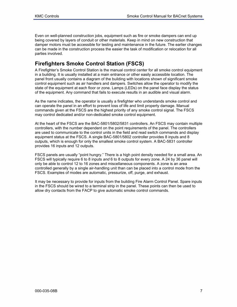
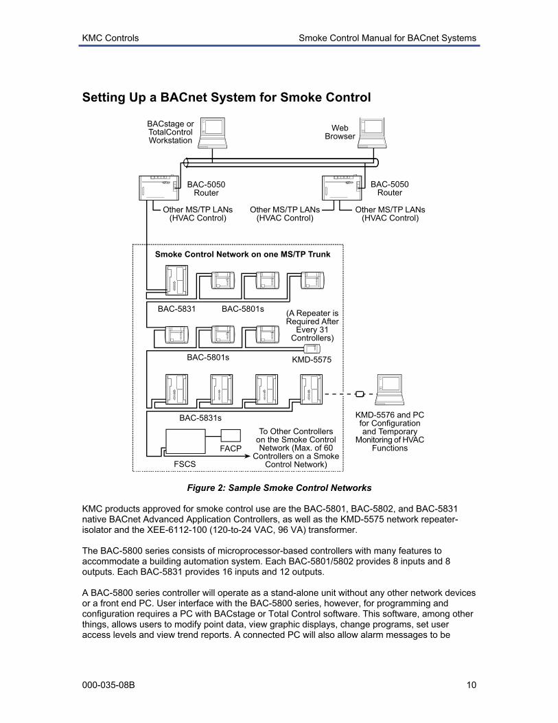


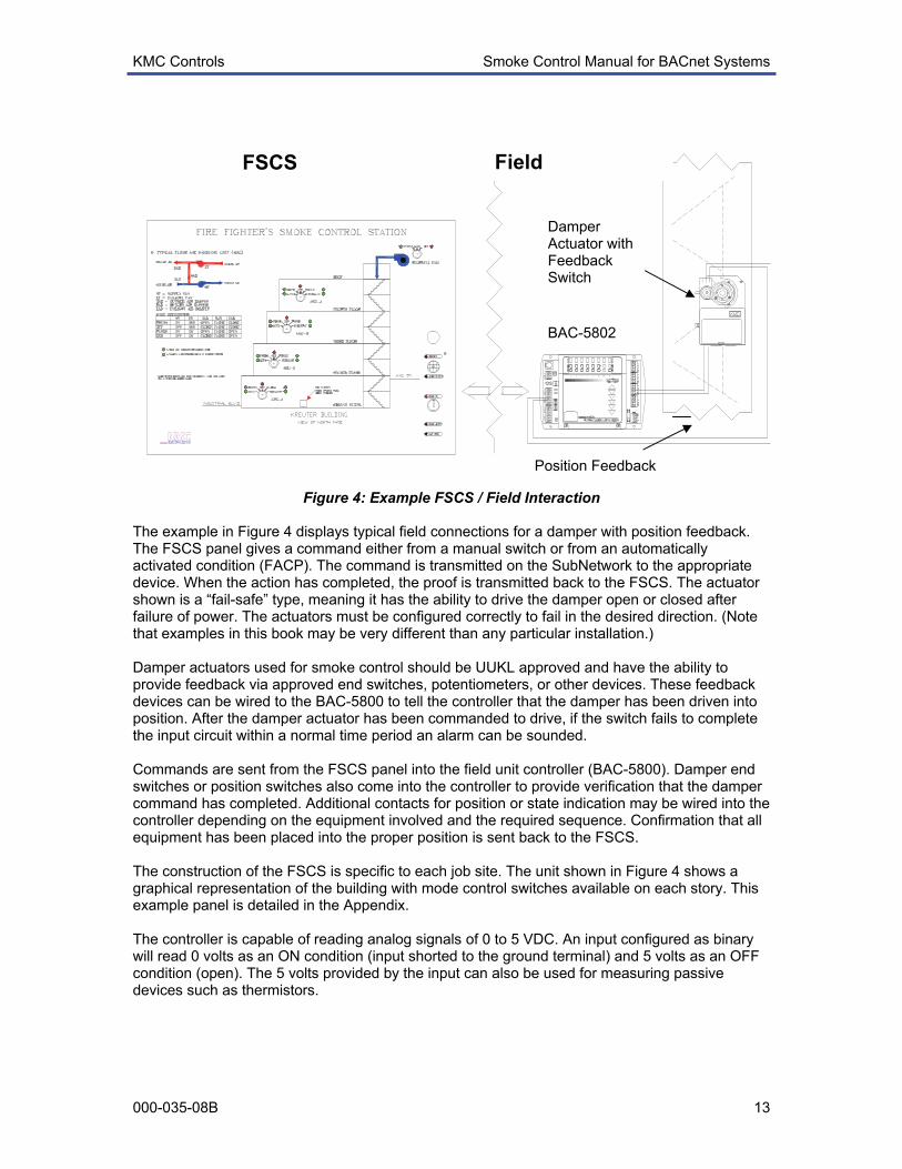


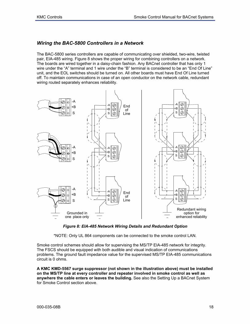


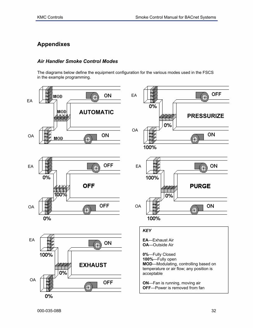


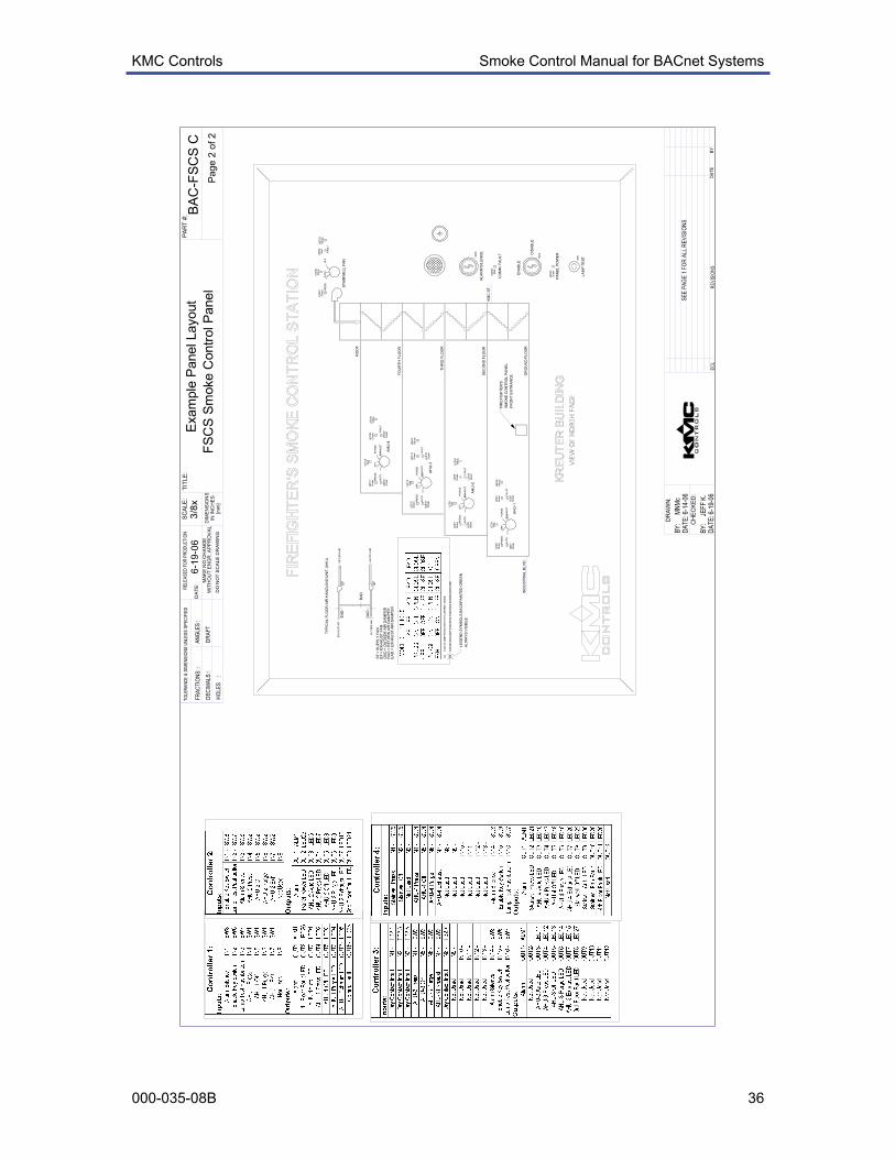


![Floor Strippers - Home | RJ Schinner Floor... · [Floor Care] 22 [Floor Care] 23 Floor Finishes & Sealers KEY CHARACTERISTICS BEST FOR PRODUCT CODE % OFF-THE-MOP MAINTENANCE SEMI-PERMANENT](https://static.documents.pub/doc/80x56/5b846d957f8b9a784a8c4361/floor-strippers-home-rj-schinner-floor-floor-care-22-floor-care-23.jpg)


