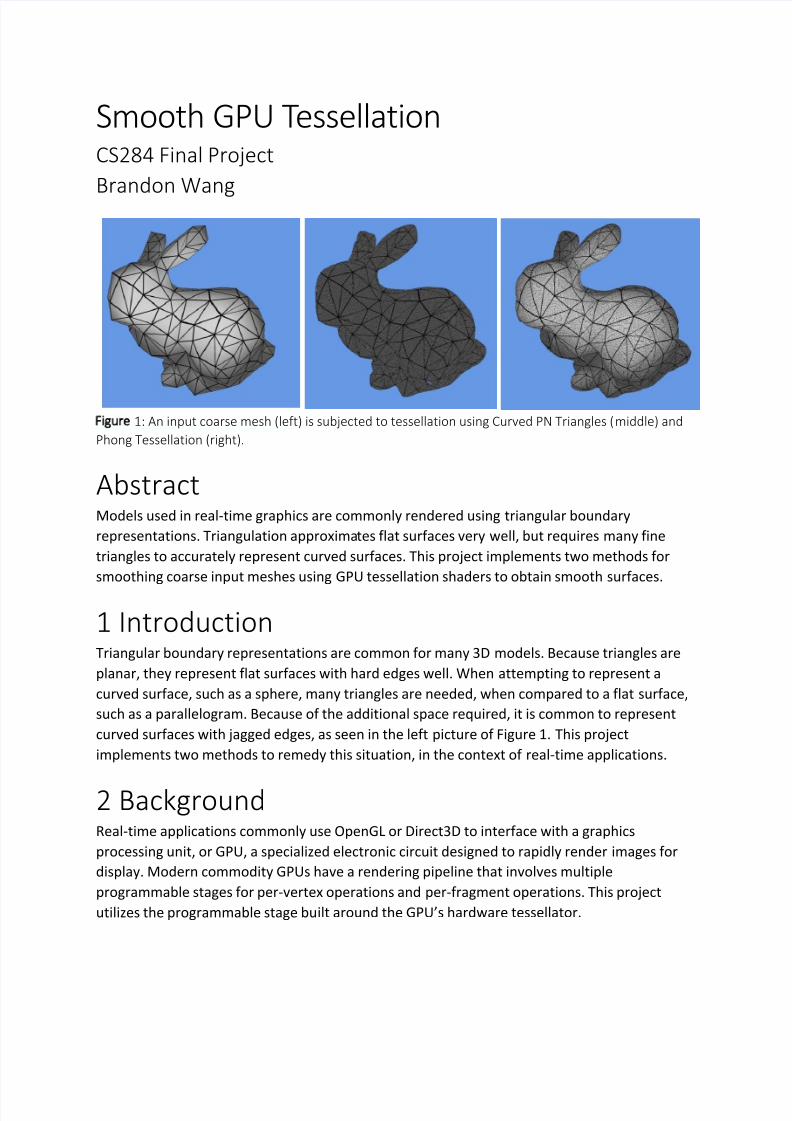
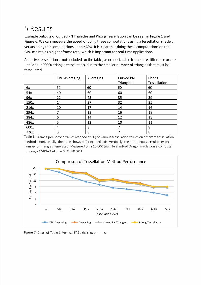
Smooth GPU T essellationCS284 Final Project Brandon Wang Figure 1: An input coarse mesh (left) is subjected to tessellation using Curved PN Triangles ( middle) and Phong Tessellation (right). Abstract Models used in real-time graphics are commonly rendered using triangular boundary representations. Triangulation approximates flat surfaces very well, but requires many fine triangles to accurately represent curved surfaces. This project implements two methods for smoothing coarse input meshes using GPU tessellation shaders to obtain smooth surfaces. 1 Introduction Triangular boundary representations are common for many 3D models. Because triangles are planar, they represent flat surfaces with hard edges well. When attempting to represent a curved surface, such as a sphere, many triangles are needed, when compared to a flat surface, such as a parallelogram. Because of the additional space required, it is common to represent curved surfaces with jagged edges, as seen in the left picture of Figure 1. This project implements two methods to remedy this situation, in the context of real-time applications. 2 Background Real-time applications commonly use OpenGL or Direct3D to interface with a graphics processing unit, or GPU, a specialized electronic circuit designed to rapidly render images for display. Modern commodity GPUs have a rendering pipeline that involves multiple programmable stages for per-vertex operations and per-fragment operations. This project utilizes the programmable stage built around the GPU’s hardware tessellator.
The number of triangles affects the speed of rendering in modern real-time GPU-based
approaches in two ways. First, the GPU must rasterize every triangle. Second, the CPU must
pass the triangles into graphics memory. Because these constraints are kept in mind, many
models are coarsely triangulated, to reduce their rendering cost. However, when an object is
large on a screen, the triangulation’s approximation artifacts are very visible, shown as jagged
edges on what should be a smooth surface, shown in the left picture in Figure 1.
Subdivision surfaces can represent curved surfaces by utilizing a coarse control point mesh.
These subdivision surfaces are commonly defined recursively [Catmull and Clark 1978]. To be
implemented in a GPU tessellator, a limit-surface representation [Stam 1998] is common, as
new points can be generated in a single pass. However, a limit-surface method involves pre-
computation on the mesh before tessellation, has issues at extraordinary vertices, and can be
quite slow when implemented on a GPU [Loop and Schaefer 2008]. Furthermore, meshes used
with subdivision schemes are typically modeled with the scheme in mind, and may generate
vastly inconsistent meshes with differing subdivision methods [Stam and Loop 2003].
Representations other than boundary representations can exhibit curved surfaces. However,
for real-time applications, these representations are often triangulated to interface with the
existing GPU rasterization pipeline that typically accepts only planar geometry. Alternative real-
time approaches exist, such as real-time ray-tracing [Parker et al. 2010] that may handle more
representations of geometry. This project, however, will focus on using the GPU rasterization
pipeline.
2 Tessellation
Tessellation, in its most basic form, is breaking down polygons into finer pieces. A square can betessellated into two triangles by splitting the shape along its diagonal. Although tessellation can
be done on the CPU, doing so would increase the number of polygons that must be transmitted
to the GPU. This may impact performance when using a large number of polygons, as the
memory bandwidth between the CPU and GPU is finite. Additionally, GPUs are typically
designed with parallelism in mind. Because tessellation is independent per-polygon, doing
many tessellations in parallel will speed up the computation. The actual speed-up can be seen
in the results section.
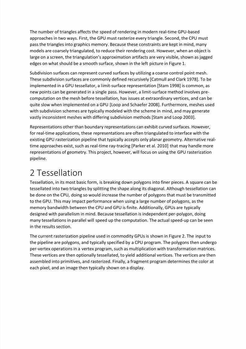
The current rasterization pipeline used in commodity GPUs is shown in Figure 2. The input to
the pipeline are polygons, and typically specified by a CPU program. The polygons then undergoper-vertex operations in a vertex program, such as multiplication with transformation matrices.
These vertices are then optionally tessellated, to yield additional vertices. The vertices are then
assembled into primitives, and rasterized. Finally, a fragment program determines the color at
each pixel, and an image then typically shown on a display.
Figure 2: A modern GPU rasterization pipeline. Steps shown in blue are fixed-function. Steps shown in
green are programmable. Steps with a dotted border are optional.
The Tessellation Control Program (TCP) controls the number of additional polygons to generate,
per input polygon. The tessellation step of actually generating the additional vertices is not
programmable. The Tessellation Evaluation Program (TEP) controls the location of additional
points within an input polygon.
The TCP operates on a per-vertex level. We will revisit this program in adaptive tessellation. For
uniform tessellation, this can simply set a user-defined variable for the number of new trianglesto generate.
The tessellator will generate additional vertices within a given polygon. These additional
vertices are then passed to the TEP, along with barycentric coordinates of the generated vertex
relative to the input polygon. We smooth our input geometry by moving the generated vertices
in the TEP.
3 Smooth Tessellation
By manipulating the location of an additional vertex in the TEP, we can smooth the model bymore closely approximating a smooth surface. This project implement two existing methods,
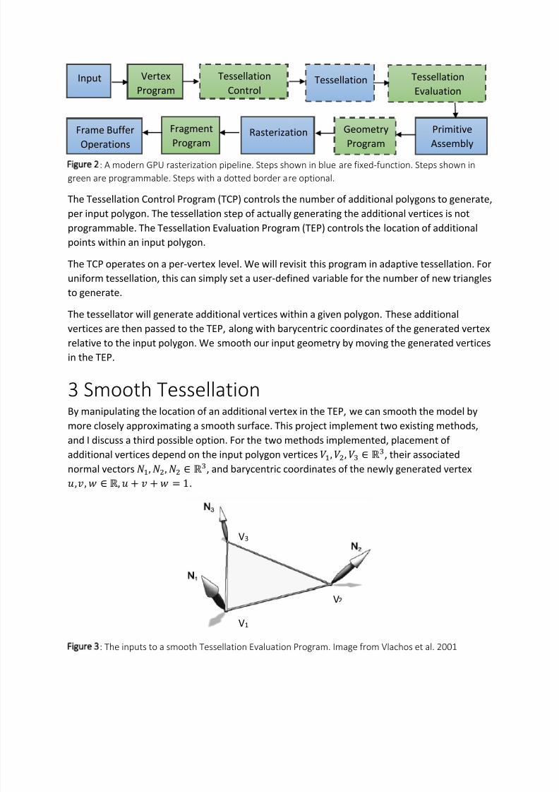
and I discuss a third possible option. For the two methods implemented, placement of
additional vertices depend on the input polygon vertices , , ∈ ℝ, their associated
normal vectors, , ∈ ℝ, and barycentric coordinates of the newly generated vertex,, ∈ ℝ, + + = 1.
Figure 3: The inputs to a smooth Tessellation Evaluation Program. Image from Vlachos et al. 2001
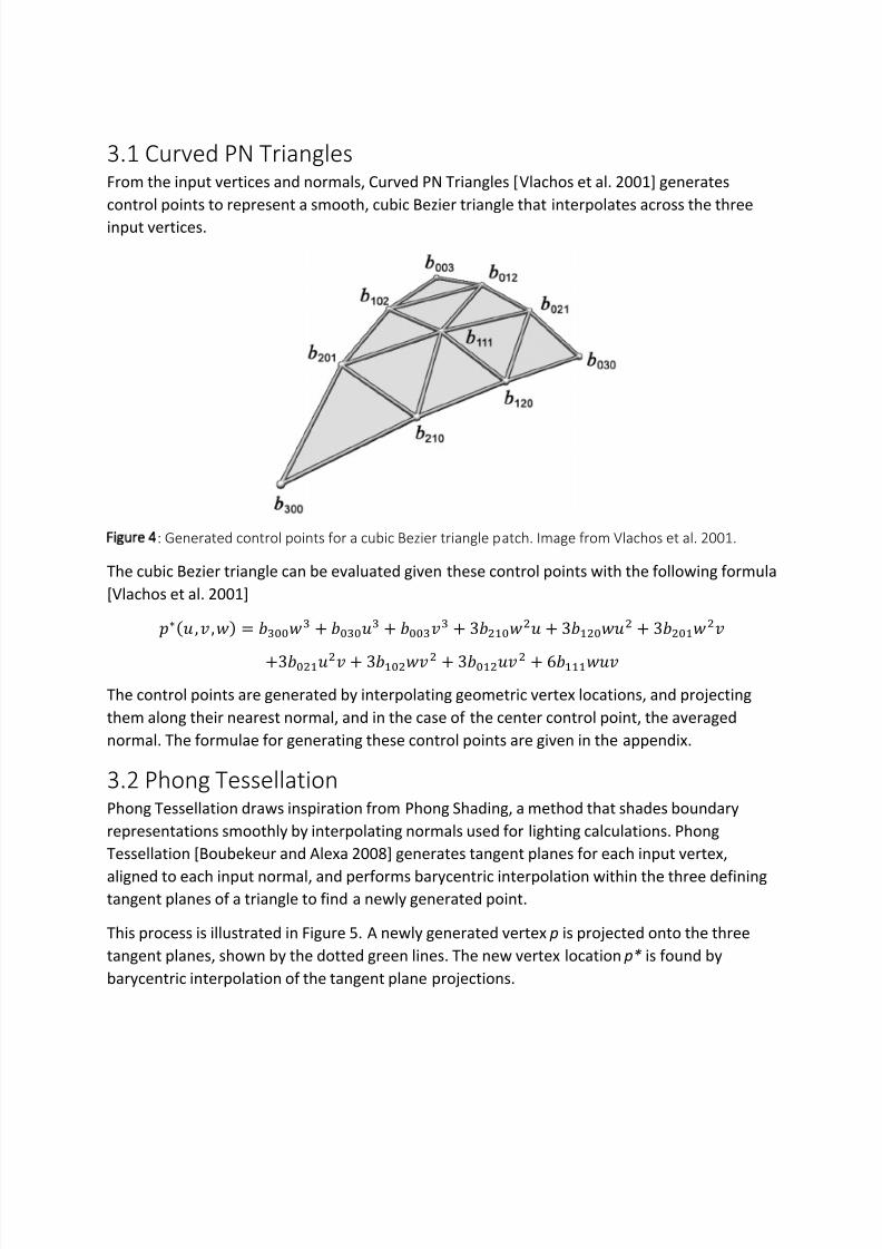
3.1 Curved PN TrianglesFrom the input vertices and normals, Curved PN Triangles [Vlachos et al. 2001] generates
control points to represent a smooth, cubic Bezier triangle that interpolates across the three
input vertices.
Figure 4: Generated control points for a cubic Bezier triangle patch. Image from Vlachos et al. 2001.
The cubic Bezier triangle can be evaluated given these control points with the following formula
[Vlachos et al. 2001]
∗
, , = 00
+ 00
+ 00
+ 30
+ 30
+ 30
+30 + 30 + 30 + 6
The control points are generated by interpolating geometric vertex locations, and projecting
them along their nearest normal, and in the case of the center control point, the averaged
normal. The formulae for generating these control points are given in the appendix.
3.2 Phong TessellationPhong Tessellation draws inspiration from Phong Shading, a method that shades boundary
representations smoothly by interpolating normals used for lighting calculations. Phong
Tessellation [Boubekeur and Alexa 2008] generates tangent planes for each input vertex,
aligned to each input normal, and performs barycentric interpolation within the three definingtangent planes of a triangle to find a newly generated point.
This process is illustrated in Figure 5. A newly generated vertex p is projected onto the three
tangent planes, shown by the dotted green lines. The new vertex location p* is found by
barycentric interpolation of the tangent plane projections.
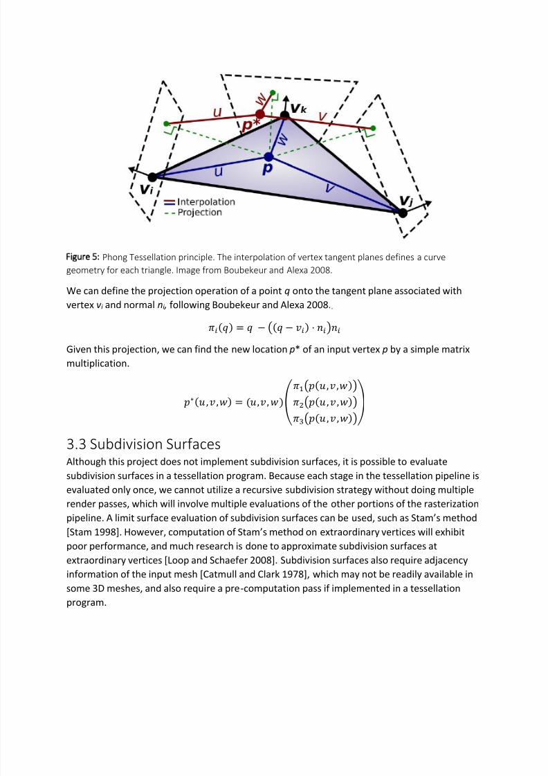
Figure 5: Phong Tessellation principle. The interpolation of vertex tangent planes defines a curve
geometry for each triangle. Image from Boubekeur and Alexa 2008.
We can define the projection operation of a point q onto the tangent plane associated with
vertex v i and normal ni , following Boubekeur and Alexa 2008.. = − ( − ⋅ ) Given this projection, we can find the new location p* of an input vertex p by a simple matrix
multiplication.
∗ , , = ,,
(,,)(, ,)(, ,)
3.3 Subdivision SurfacesAlthough this project does not implement subdivision surfaces, it is possible to evaluate
subdivision surfaces in a tessellation program. Because each stage in the tessellation pipeline is
evaluated only once, we cannot utilize a recursive subdivision strategy without doing multiple
render passes, which will involve multiple evaluations of the other portions of the rasterization
pipeline. A limit surface evaluation of subdivision surfaces can be used, such as Stam’s method
[Stam 1998]. However, computation of Stam’s method on extraordinary vertices will exhibit
poor performance, and much research is done to approximate subdivision surfaces atextraordinary vertices [Loop and Schaefer 2008]. Subdivision surfaces also require adjacency
information of the input mesh [Catmull and Clark 1978], which may not be readily available in
some 3D meshes, and also require a pre-computation pass if implemented in a tessellation
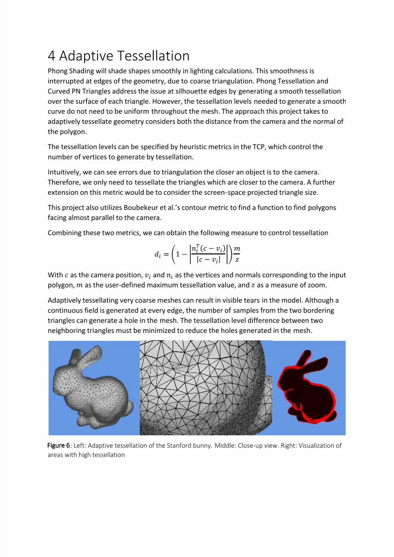


![Adaptive Cube Tessellation for Topologically Correct ... · Adaptive Cube Tessellation for Topologically Correct Isosurfaces ... [PT90]. This method is ... Tessellation for Topologically](https://static.documents.pub/doc/80x56/5adfba127f8b9a5a668ca39b/adaptive-cube-tessellation-for-topologically-correct-cube-tessellation-for-topologically.jpg)


