148
Part Number MN/SMS7000.IOM Revision 3 SMS-7000 Modem Protection Switch Installation and Operation Manual
Part Number MN/SMS7000.IOM Revision 3
SMS-7000Modem Protection Switch
Installation and Operation Manual

Filename: T_ERRATA 1
Errata A Comtech EF Data Documentation Update
Subject: Changes to Table 3-4 (Interface Configuration Jumper Settings) Date: October 5, 2001 Document: SMS-7000 Modem Protection Switch
Installation and Operation Manual, Revision 3, September 30, 1999
Part Number: MN/SMS7000.EA3 Collating Instructions: Attach this page to page 2-11 Comments:
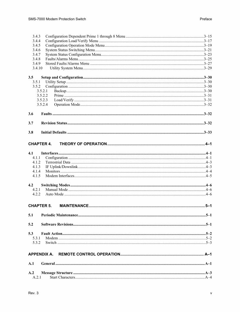
The following changes provide updated information for Figure2-2. This information will be incorporated into the next revision.
Change Specifics: See following page…….
Filename: T_ERRATA 2
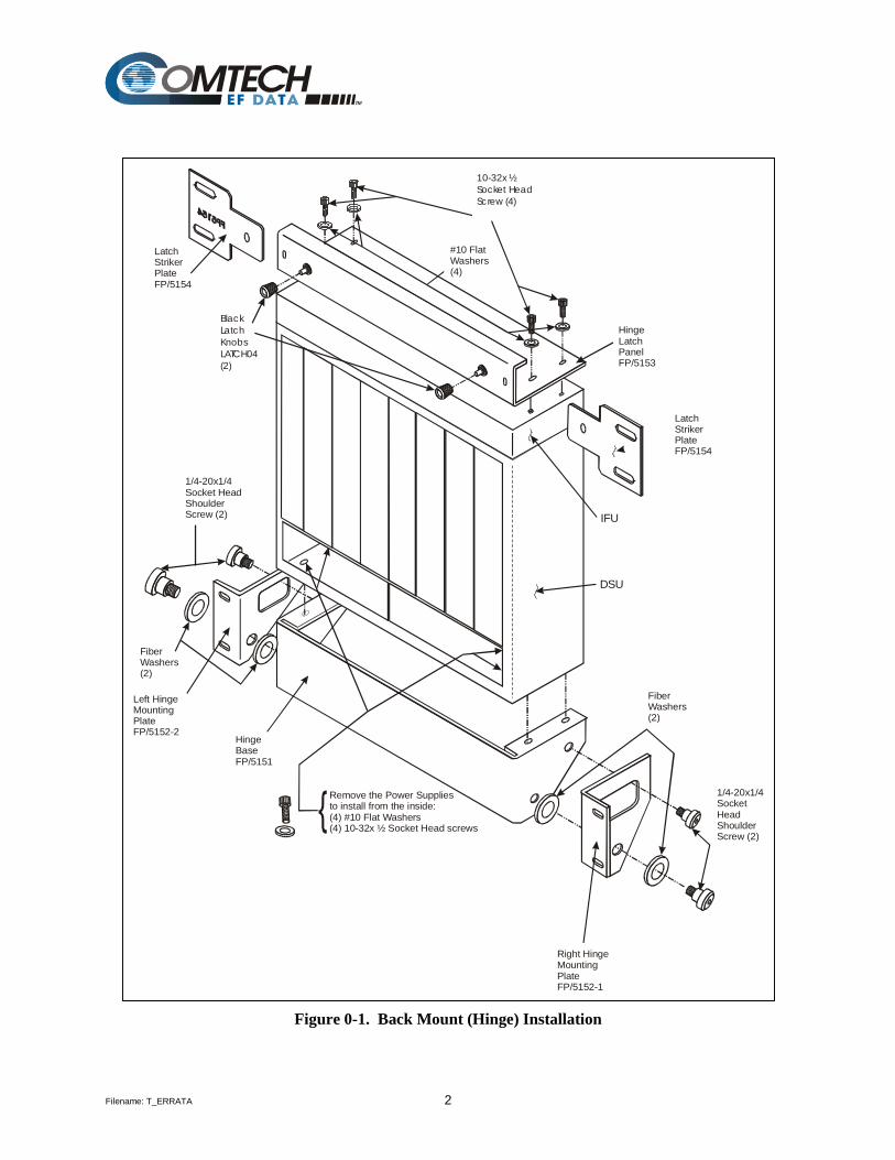
Figure 0-1. Back Mount (Hinge) Installation
10-32x ½Socket HeadScrew (4)
Black Latch KnobsLATCH04(2)
LatchStrikerPlateFP/5154
1/4-20x1/4Socket HeadShoulderScrew (2)
1/4-20x1/4SocketHeadShoulderScrew (2)
FiberWashers(2)
FiberWashers(2)
#10 Flat Washers(4)
HingeBaseFP/5151
Left HingeMountingPlateFP/5152-2
Right HingeMountingPlateFP/5152-1
DSU
IFU
HingeLatchPanelFP/5153
LatchStrikerPlateFP/5154
Remove the Power Supplies to install from the inside:
#10 Flat Washers(4) (4) 10-32x ½ Socket Head screws

Filename: T_ERRATA 1
Errata B Comtech EFData Documentation Update
Subject: Changes to Table 3-4 (Initial Defaults) Date: October 5, 2001 Document: SMS-7000 Modem protection Switch Installation and Operation
Manual, Rev. 3, dated September 30, 1999 Part Number: MN/SMS7000.EB3 Collating Instructions: Attach this page to page 3-33 Comments: The following changes provide updated information to Table 3-4.
Table 3-4. Initial Defaults Configuration Backup #n (n = 1 or 2)
Backup Mod #n Off Backup #1 Multiplexer No Backup Demod #n Off Backup #2 Mulitiplexer No Backup #n Switching Mode Independent
Configuration Independent Prime #n (n = 1 through 8) Prime Mod #n Off Prime Demod #6, 7 Delay None Prime Mod #1, 2, 3, 4 Priority Low Prime Demod #8 Delay None Prime Mod #5, 6 Priority Low Prime #1, 2, 3, 4 Multiplexer No Prime Mod #7, 8 Priority Low Prime #5, 6, 7, 8 Multiplexer No Prime Mod #1 through 7 Delay None D&I #1, 2, 3, 4 Unbalanced Prime Mod # 8 Delay None External Clock #1, 2, 3, 4 Unbalanced Prime Demod #n Off Insert Data Input #1, 2, 3, 4 Normal Prime Demod #1, 2, 3, 4 Priority Low D&I #5, 6, 7, 8 Unbalanced Prime Demod #5, 6 Priority Low External Clock #5, 6, 7, 8 Unbalanced Prime Demod #7, 8 Priority Low Insert Data Input #5, 6, 7, 8 Normal Prime Demod # 1 through 5 Delay None
Configuration Dependent Prime #n (n = 1 through 8) Prime Mod #n Off Prime #1, 2, 3, 4 Multiplexer No Prime Demod #n Off Prime #5, 6, 7, 8 Multiplexer No Prime Mod #1, 2, 3, 4 Priority Low D&I #1, 2, 3, 4 Unbalanced Prime Mod #5, 6 Priority Low External Clock #1, 2, 3, 4 Unbalanced Prime Mod #7, 8 Priority Low Insert Data Input #1, 2, 3, 4 Normal Prime Mod #1 through 5 Delay None D&I #5, 6, 7, 8 Unbalanced Prime Mod #6, 7 Delay None External Clock #5, 6, 7, 8 Unbalanced Prime Mod # 8 Delay None Insert Data Input #5, 6, 7, 8 Normal
Configuration Operation Mode Operation Mode Manual
Utility System Time Current Parity Even Date Current Remote Type EIA-485 (2-
Wire) Remote Baud Rate 9600 bit/s Mode Control Baud Rate 9600 bit/s


Filename: T_ERRATA 1
Errata C Comtech EFData Documentation Update
Subject: Changes to Related Documents Date: October 13, 2003 Document: SMS-7000 Modem protection Switch Installation and Operation
Manual, Rev. 3, dated September 30, 1999 Part Number: MN/SMS7000.EC3 Collating Instructions: Attach this page to page viii
Related Documents The following documents are referenced in this manual:
• Department of Defense (DOD) MIL-STD-188-114A, “Electrical Characteristics of Digital Interface Circuits”
• M-2000 Multiplexer Installation and Operation Manual • Comtech EF Data CRS-280L 1:N Redundancy Switch Installation and Operation Manual


Copyright © Comtech EFData, 2000. All rights reserved. Printed in the USA. Comtech EFData, 2114 West 7th Street, Tempe, Arizona 85281 USA, (480) 333-2200, FAX: (480) 333-2161.
SMS-7000 Modem Protection Switch
Installation and Operation Manual
Part Number MN/SMS7000.IOM Revision 3
September 30, 1999
Comtech EFData is an ISO 9001 Registered Company.

ii Rev. 3
Customer Support
Contact the Comtech EFData Customer Support Department for: • Product support or training • Information on upgrading or returning a product • Reporting comments or suggestions concerning manuals A Customer Support representative may be reached at:
Comtech EFData Attention: Customer Support Department 2114 West 7th Street Tempe, Arizona 85281 USA (480) 333-2200 (Main Comtech EFData Number) (480) 333-4357 (Customer Support Desk) (480) 333-2161 FAX
or, E-Mail can be sent to the Customer Support Department at:
[email protected] Contact us via the web at www.comtechefdata.com.
1. To return a Comtech EFData product (in-warranty and out-of-warranty) for repair or replacement:
2. Request a Return Material Authorization (RMA) number from the Comtech
EFData Customer Support Department. 3. Be prepared to supply the Customer Support representative with the model
number, serial number, and a description of the problem. 4. To ensure that the product is not damaged during shipping, pack the product in
its original shipping carton/packaging. 5. Ship the product back to Comtech EFData. (Shipping charges should be prepaid.)
For more information regarding the warranty policies, see Warranty Policy, p. xii.
Rev. 3 iii
Table of Contents
Customer Support ...................................................................................................................................................... ii
Overview of Changes to Previous Edition ............................................................................................................. viii
Overview of Changes to Previous Edition ............................................................................................................. viii
About this Manual ................................................................................................................................................... viii
EMC Compliance ........................................................................................................................................................x
Warranty Policy........................................................................................................................................................ xii
CHAPTER 1. INTRODUCTION..........................................................................................................1–1
1.1 Overview......................................................................................................................................................1–2 1.1.1 Compatibility ...........................................................................................................................................1–2 1.1.2 Data Formats ............................................................................................................................................1–4 1.1.3 Options.....................................................................................................................................................1–5 1.1.4 Protection Switch .....................................................................................................................................1–6
1.2 Description ..................................................................................................................................................1–6 1.2.1 Switch Controller Unit (SCU)..................................................................................................................1–8 1.2.2 Data Switch Unit (DSU) ..........................................................................................................................1–9 1.2.3 IF Switch Unit (IFU)..............................................................................................................................1–11
1.3 Specifications ............................................................................................................................................1–12
CHAPTER 2. INSTALLATION...........................................................................................................2–1
2.1 Unpacking ...................................................................................................................................................2–1
2.2 Equipment Inspection ................................................................................................................................2–2 2.2.1 Included Parts...........................................................................................................................................2–2 2.2.2 Back Mount (Hinged) Hardware Kit........................................................................................................2–3 2.2.3 Top Mount Hardware Kit.........................................................................................................................2–4 2.2.4 Cables.......................................................................................................................................................2–5 2.2.5 Tools Required.........................................................................................................................................2–6
Preface SMS-7000 Modem Protection Switch
iv Rev. 3
2.3 Mounting .....................................................................................................................................................2–7 2.3.1 Description ...............................................................................................................................................2–7
2.3.1.1 Top Mount.......................................................................................................................................2–7 2.3.1.2 Back Mount .....................................................................................................................................2–7
2.3.2 Installation................................................................................................................................................2–8 2.3.2.1 Switch Control Unit.........................................................................................................................2–8 2.3.2.2 Top Mount Installation ....................................................................................................................2–8 2.3.2.3 Back Mount Installation ................................................................................................................2–10
2.4 Cable Installation......................................................................................................................................2–13 2.4.1 Interconnecting the Switch Components................................................................................................2–13
2.4.1.1 SCU (J4) to DSU (J11) Interface...................................................................................................2–15 2.4.1.2 Remote Connection .......................................................................................................................2–15 2.4.1.3 DSU (J12) to IFU (J1) ...................................................................................................................2–16 2.4.1.4 DSU J9 (BU1) Modem Connector to Backup Modem..................................................................2–16 2.4.1.5 DSU JI CH to Prime Modem.........................................................................................................2–16 2.4.1.6 IFU Connections (CP17 through CP36) ........................................................................................2–17
2.5 Configuration Setup .................................................................................................................................2–17 2.5.1 Configure Rack Setup ............................................................................................................................2–17 2.5.2 Trouble Shoot Configuration .................................................................................................................2–19
2.6 DSU Data Connections (J1 through J10)................................................................................................2–20 2.6.1 SCU Rear Panel .....................................................................................................................................2–22
2.6.1.1 User Remote (J1)...........................................................................................................................2–22 2.6.1.2 Modem Remote (J2)......................................................................................................................2–23 2.6.1.3 Switch Faults (J3)..........................................................................................................................2–23 2.6.1.4 Prime Mod (Online) Status (J6) ....................................................................................................2–24 2.6.1.5 Prime Mod (Online) Status (J5) ....................................................................................................2–25
2.6.2 DSU Terrestrial Data Interfaces .............................................................................................................2–26 2.6.2.1 EIA-422/8 kbit/s Terrestrial Data (J6)...........................................................................................2–27 2.6.2.2 V.35/EIA-232-C Terrestrial Data (J1)...........................................................................................2–29 2.6.2.3 Engineering Service Channel Data (J4).........................................................................................2–30 2.6.2.4 Alarms (J2) ....................................................................................................................................2–31 2.6.2.5 ADPCM Audio Data (J5) ..............................................................................................................2–32 2.6.2.6 Balanced G.703/Drop & Insert Data (J3) ......................................................................................2–33 2.6.2.7 Unbalanced Data Ports ..................................................................................................................2–34
2.6.3 IFU Uplink and Downlink IF (CP1 through CP16) ...............................................................................2–35
CHAPTER 3. OPERATION................................................................................................................3–1
3.1 Configuration..............................................................................................................................................3–1 3.1.1 Backup Modems ......................................................................................................................................3–2 3.1.2 Prime Modems .........................................................................................................................................3–2
3.2 Front Panel..................................................................................................................................................3–2 3.2.1 LED Indicators .........................................................................................................................................3–3 3.2.2 Front Panel Controls ................................................................................................................................3–4
3.3 Menu System...............................................................................................................................................3–5
3.4 Front Panel Menu.......................................................................................................................................3–7 3.4.1 Configuration Backup 1 and 2 Menu .......................................................................................................3–9 3.4.2 Configuration Independent Prime 1 through 8 Menu.............................................................................3–11
SMS-7000 Modem Protection Switch Preface
Rev. 3 v
3.4.3 Configuration Dependent Prime 1 through 8 Menu ...............................................................................3–15 3.4.4 Configuration Load/Verify Menu ..........................................................................................................3–17 3.4.5 Configuration Operation Mode Menu....................................................................................................3–19 3.4.6 System Status Switching Menu..............................................................................................................3–21 3.4.7 System Status Configuration Menu........................................................................................................3–23 3.4.8 Faults/Alarms Menu...............................................................................................................................3–25 3.4.9 Stored Faults/Alarms Menu ...................................................................................................................3–27 3.4.10 Utility System Menu..........................................................................................................................3–29
3.5 Setup and Configuration..........................................................................................................................3–30 3.5.1 Utility Setup ...........................................................................................................................................3–30 3.5.2 Configuration .........................................................................................................................................3–30
3.5.2.1 Backup...........................................................................................................................................3–30 3.5.2.2 Prime .............................................................................................................................................3–31 3.5.2.3 Load/Verify ...................................................................................................................................3–31 3.5.2.4 Operation Mode.............................................................................................................................3–32
3.6 Faults .........................................................................................................................................................3–32
3.7 Revision Status..........................................................................................................................................3–32
3.8 Initial Defaults ..........................................................................................................................................3–33
CHAPTER 4. THEORY OF OPERATION..........................................................................................4–1
4.1 Interfaces.....................................................................................................................................................4–1 4.1.1 Configuration ...........................................................................................................................................4–1 4.1.2 Terrestrial Data ........................................................................................................................................4–3 4.1.3 IF Uplink/Downlink .................................................................................................................................4–3 4.1.4 Monitors ...................................................................................................................................................4–4 4.1.5 Modem Interfaces.....................................................................................................................................4–5
4.2 Switching Modes.........................................................................................................................................4–6 4.2.1 Manual Mode ...........................................................................................................................................4–6 4.2.2 Auto Mode ...............................................................................................................................................4–6
CHAPTER 5. MAINTENANCE...........................................................................................................5–1
5.1 Periodic Maintenance.................................................................................................................................5–1
5.2 Software Revisions......................................................................................................................................5–1
5.3 Fault Action.................................................................................................................................................5–2 5.3.1 Modem .....................................................................................................................................................5–2 5.3.2 Switch ......................................................................................................................................................5–3
APPENDIX A. REMOTE CONTROL OPERATION............................................................................. A–1
A.1 General .......................................................................................................................................................A–1
A.2 Message Structure .....................................................................................................................................A–3 A.2.1 Start Characters...................................................................................................................................A–4

Preface SMS-7000 Modem Protection Switch
vi Rev. 3
A.2.2 Command/Response ...........................................................................................................................A–4 A.2.3 End Character .....................................................................................................................................A–5
A.3 Configuration Commands/Responses......................................................................................................A–6 A.3.1 Backup Modem...................................................................................................................................A–6 A.3.2 Prime Modem .....................................................................................................................................A–7 A.3.3 Switch .................................................................................................................................................A–8 A.3.4 Breakout..............................................................................................................................................A–9 A.3.5 System ................................................................................................................................................A–9 A.3.6 Mode.................................................................................................................................................A–10
A.4 Status Commands/Responses .................................................................................................................A–11
A.5 Stored Faults ............................................................................................................................................A–20
A.6 About Switch............................................................................................................................................A–21
APPENDIX B. M-2000 MULTIPLEXER UTILIZATION ...................................................................... B–1
B.1 Installation .................................................................................................................................................B–1
B.2 Operation ...................................................................................................................................................B–3
Figures Figure 1-1. SMS-7000 ..............................................................................................................................................1–1 Figure 1-2. Block diagram........................................................................................................................................1–7 Figure 1-3. SCU front panel .....................................................................................................................................1–8 Figure 1-4. SCU rear panel.......................................................................................................................................1–8 Figure 1-5. DSU/IFU terrestrial side ........................................................................................................................1–9 Figure 1-6. DSU/IFU modem side..........................................................................................................................1–10 Figure 2-1. Top mount installation ...........................................................................................................................2–9 Figure 2-2. Back mount (hinge) installation ...........................................................................................................2–11 Figure 2-3. Hinge mount, side view .......................................................................................................................2–12 Figure 2-4. Hinge mount, top view.........................................................................................................................2–12 Figure 2-5. Typical switch installation ...................................................................................................................2–14 Figure 2-6. SCU rear panel.....................................................................................................................................2–22 Figure 2-7. DSU/IFU terrestrial side ......................................................................................................................2–26 Figure 3-1. SMS-7000 front panel view ...................................................................................................................3–1 Figure 3-2. Main menu .............................................................................................................................................3–7 Figure 3-3. Configuration backup 1 and 2 menu ......................................................................................................3–8 Figure 3-4. Configuration independent prime 1 through 8 menu ...........................................................................3–10 Figure 3-5. Configuration dependent prime 1 through 8 menu ..............................................................................3–14 Figure 3-6. Configuration load/verify menu...........................................................................................................3–16 Figure 3-7. Configuration operation mode menu ...................................................................................................3–18 Figure 3-8. System status switching menu .............................................................................................................3–20 Figure 3-9. System status configuration menu .......................................................................................................3–22 Figure 3-10. Faults/alarms menu ............................................................................................................................3–24 Figure 3-11. Stored faults/alarms menu..................................................................................................................3–26 Figure 3-12. Utility system menu ...........................................................................................................................3–28 Figure 4-1. IF switch block diagram.........................................................................................................................4–2 Figure B-1. Terrestrial data interconnections ...........................................................................................................b–2

SMS-7000 Modem Protection Switch Preface
Rev. 3 vii
Tables
Table 1-1. SMS-7000 modem hardware compatibility.............................................................................................1–3 Table 1-2. Data formats ............................................................................................................................................1–4 Table 1-3. Options ....................................................................................................................................................1–5 Table 1-4. Protection switch .....................................................................................................................................1–6 Table 1-5. SMS-7000 specifications.......................................................................................................................1–12 Table 2-1. 50-pin cable ...........................................................................................................................................2–16 Table 2-2. Trouble shooting ...................................................................................................................................2–19 Table 2-3. DSU data connections (J1 through J10) ................................................................................................2–20 Table 2-4. User remote EIA-485/EIA-232 connector (J1) .....................................................................................2–22 Table 2-5. Modem remote EIA-485 connector (J2)................................................................................................2–23 Table 2-6. Switch faults connector (J3) ..................................................................................................................2–23 Table 2-7. Prime mod online connector (J6) ..........................................................................................................2–24 Table 2-8. Prime demod online connector (J5).......................................................................................................2–25 Table 2-9. EIA-422 terrestrial data connectors (J6)................................................................................................2–27 Table 2-10. V.35/EIA-232 terrestrial data connectors (J1).....................................................................................2–29 Table 2-11. Engineering service channel data connectors (J4)...............................................................................2–30 Table 2-12. Alarms (J2) connectors........................................................................................................................2–31 Table 2-13. ADPCM audio data (J5) connectors....................................................................................................2–32 Table 2-14. Balanced G.703/drop & insert data connectors (J3)............................................................................2–33 Table 2-15. Unbalanced data connectors ................................................................................................................2–34 Table 2-16. IFU uplink/IF downlink data connectors.............................................................................................2–35 Table 3-1. LED indicators ........................................................................................................................................3–3 Table 3-2. Front panel keypad ..................................................................................................................................3–4 Table 3-3. Revision status.......................................................................................................................................3–32 Table 3-4. Initial defaults........................................................................................................................................3–33 Table 4-1. DSM interfaces........................................................................................................................................4–3 Table 4-2. SCU chassis connectors...........................................................................................................................4–4 Table 4-3. SCU rear panel connectors ......................................................................................................................4–5 Table 5-1. Switch fault analysis................................................................................................................................5–3 Table A-1. SMS-7000 remote control: SMS-658/SMS-758 comparison table ........................................................a–2 Table B-1. SMS-7000/M-2000 50-pin to 37-pin interface cable pinouts .................................................................b–3

Preface SMS-7000 Modem Protection Switch
viii Rev. 3
Overview of Changes to Previous Edition
This revision supersedes part number MN/SMS7000 Rev. 2 dated October 3, 1997. A summary of the changes made for Rev. 2 includes: Chapter 1 Updated Compatibility and Data Formats paragraph and specified that
the SDM-300 modem must be the 50-pin configuration. Added Options paragraph. Revised Figure 1-2 to include cable part numbers. Updated specifications paragraph to the current specification. Relocated mounting information to Chapter 2.
Chapter 2 Added Equipment Inspection paragraphs to reflect mounting kits and required tooling. Added cable information. Revised mounting instructions by including description and installation information. Added trouble shooting information for installation procedures.
Chapter 3 Updated software menu from version 2.1.7 to 2.1.8. Added revision emulation and initial default paragraphs.
Appendix A Updated to software version 2.1.8.
General Deleted Mounting appendix. Reidentified Multiplexer section as Appendix B.
About this Manual
This manual provides installation and operation information for the Comtech EFData SMS-7000 Modem Protection Switch. This is a technical document intended for earth station engineers, technicians, and operators responsible for the operation and maintenance of the SMS-7000.
Related Documents
The following documents are referenced in this manual:
• Department of Defense (DOD) MIL-STD-188-114A, “Electrical Characteristics of Digital Interface Circuits”
• M-2000 Multiplexer Installation and Operation Manual
SMS-7000 Modem Protection Switch Preface
Rev. 3 ix
Conventions and References
Cautions and Warnings
CAUTION
CAUTION indicates a hazardous situation that, if not avoided, may result in minor or moderate injury. CAUTION may also be used to indicate other unsafe practices or risks of property damage.
WARNING
WARNING indicates a potentially hazardous situation that, if not avoided, could result in death or serious injury.
Metric Conversion
Metric conversion information is located on the inside back cover of this manual. This information is provided to assist the operator in cross-referencing English to Metric conversions.
Recommended Standard Designations
Recommended Standard (RS) Designations have been superseded by the new designation of the Electronic Industries Association (EIA). References to the old designations are shown only when depicting actual text displayed on the screen of the unit (RS-232, RS-485, etc.). All other references in the manual will be shown with the EIA designations (EIA-232, EIA-485, etc.) only.
Military Standards
References to “MIL-STD-188” apply to the 114A series (i.e., MIL-STD-188-114A), which provides electrical and functional characteristics of the unbalanced and balanced voltage digital interface circuits applicable to both long haul and tactical communications. Specifically, these references apply to the MIL-STD-188-114A electrical characteristics for a balanced voltage digital interface circuit, Type 1 generator, for the full range of data rates. For more information, refer to the Department of Defense (DOD) MIL-STD-188-114A, “Electrical Characteristics of Digital Interface Circuits.”
Trademarks
Other product names mentioned in this manual may be trademarks or registered trademarks of their respective companies and are hereby acknowledged.
Preface SMS-7000 Modem Protection Switch
x Rev. 3
Reporting Comments or Suggestions Concerning this Manual
Comments and suggestions regarding the content and design of this manual will be appreciated. To submit comments, please contact the Comtech EFData Customer Support Department.
EMC Compliance
EN55022 Compliance
This equipment meets EN55022. This is a Class A product. In a domestic environment it may cause radio interference in which the user may be required to take adequate measures.
Federal Communications Commission (FCC)
Note: All cables shall be shielded. This equipment has been tested and found to comply with the limits for a Class A digital device, pursuant to Part 15 of the FCC rules. These limits are designed to provide reasonable protection against harmful interference when the equipment is operated in a commercial environment. This equipment generates, uses, and can radiate radio frequency energy and, if not installed and used in accordance with the instruction manual, may cause harmful interference to radio communications. Operation of this equipment in a residential area is likely to cause harmful interference in which case the user will be required to correct the interference at his own expense.

SMS-7000 Modem Protection Switch Preface
Rev. 3 xi
Low Voltage Directive (LVD)
The following information is applicable for the European Low Voltage Directive (EN60950):
<HAR> Type of power cord required for use in the European Community.
! CAUTION: Double-pole/Neutral Fusing. ACHTUNG: Zweipolige bzw. Neutralleiter-Sicherung.
International Symbols:
Symbol Definition Symbol Definition
Alternating Current.
Protective Earth
Fuse.
Chassis Ground.
Notes:
1. For additional symbols, refer to “Cautions” listed earlier in this preface. 2. Applicable testing is routinely performed as a condition of manufacturing on all
units to ensure compliance with requirements of EN60950 for Safety.

Preface SMS-7000 Modem Protection Switch
xii Rev. 3
Warranty Policy
This Comtech EFData product is warranted against defects in material and workmanship for a period of one year from the date of shipment. During the warranty period, Comtech EFData will, at its option, repair or replace products that prove to be defective. For equipment under warranty, the customer is responsible for freight to Comtech EFData and all related custom, taxes, tariffs, insurance, etc. Comtech EFData is responsible for the freight charges only for return of the equipment from the factory to the customer. Comtech EFData will return the equipment by the same method (i.e., Air, Express, Surface) as the equipment was sent to Comtech EFData.
Limitations of Warranty
The foregoing warranty shall not apply to defects resulting from improper installation or maintenance, abuse, unauthorized modification, or operation outside of environmental specifications for the product, or, for damages that occur due to improper repackaging of equipment for return to Comtech EFData. No other warranty is expressed or implied. Comtech EFData specifically disclaims the implied warranties of merchantability and fitness for particular purpose.
Exclusive Remedies
The remedies provided herein are the buyer's sole and exclusive remedies. Comtech EFData shall not be liable for any direct, indirect, special, incidental, or consequential damages, whether based on contract, tort, or any other legal theory.
Disclaimer Comtech EFData has reviewed this manual thoroughly in order that it will be an easy-to-use guide to your equipment. All statements, technical information, and recommendations in this manual and in any guides or related documents are believed reliable, but the accuracy and completeness thereof are not guaranteed or warranted, and they are not intended to be, nor should they be understood to be, representations or warranties concerning the products described. Further, Comtech EFData reserves the right to make changes in the specifications of the products described in this manual at any time without notice and without obligation to notify any person of such changes. If you have any questions regarding your equipment or the information in this manual, please contact the Comtech EFData Customer Support Department.
Rev. 3 1–1
1Chapter 1. INTRODUCTION
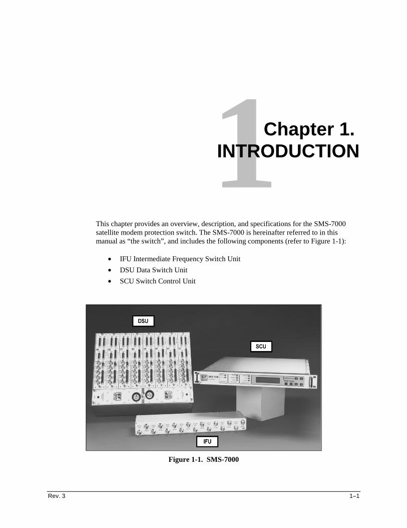
This chapter provides an overview, description, and specifications for the SMS-7000satellite modem protection switch. The SMS-7000 is hereinafter referred to in thismanual as “the switch”, and includes the following components (refer to Figure 1-1):
• IFU Intermediate Frequency Switch Unit
• DSU Data Switch Unit
• SCU Switch Control Unit
Figure 1-1. SMS-7000
Introduction SMS-7000 Modem Protection Switch
1–2 Rev. 3
1.1 Overview
The switch is specifically designed to perform automatic redundancy switching for anycombination of up to two backup and eight prime Comtech EFData satellite modems. Upto eight separate uplinks and downlinks can be accessed by the user at any time.
Each switch channel has a built-in breakout panel that is automatically configured tosupport overhead, non-overhead, and programmable data-type modems. Configurationand control of the switch and attached modems may be performed from a terminal or PCconnected to the switch remote port (refer to Appendix A); or directly from the switchfront panel (refer to Chapter 3).
The switch is compatible with the M-2000 multiplexer (refer to Appendix C for moreinformation).
The switch is tested and certified to CE-Mark requirements.
1.1.1 Compatibility
The switch is designed to operate with the following Comtech EFData modems:
• SDM-100 • SDM-300A (see Note)
• SDM-308-4 • SDM-6000
• SDM-308-5 • SDM-8000
• SDM-309B • SLM-3650 (see Note)
• SDM-650B • SLM-6650
• SDM-300 (see Note) • SLM-8650
Note: Use the 50-pin D connector configuration with the switch.

SMS-7000 Modem Protection Switch Introduction
Rev. 3 1–3
For modem compatibility, refer to Table 1-1.
Table 1-1. SMS-7000 Modem Hardware Compatibility
Rack Setup Backup CommentsSDM-308-4SDM-6000
Either SDM-6000 must be configured as Modem Type 1 to be compatiblewith SDM-308-4 (M1200P).
Note: SDM-6000 must be configured as Modem Type 4 to becompatible with SDM-308-4 (old IDR interface). (See Note 1)
SDM-308-5SDM-6000
Either SDM-6000 must be configured as Modem Type 3 to be compatiblewith SDM-308-5. (See Note 1)
SDM-309BSDM-6000
Either SDM-6000 must be configured as Modem Type 2 to be compatiblewith SDM-309 (M1200P). (See Note 1)
SDM-308-4SDM-8000
Either SDM-8000 must be configured as Modem Type 1 to be compatiblewith SDM-308-4.(M1200P).
Note: SDM-8000 must be configured as Modem Type 4 to becompatible with SDM-308-4 (old IDR interface) or Type 5 to becompatible with SDM-308-4 (M1200/RS). (See Note 1)
SDM-308-5SDM-8000
Either SDM-8000 must be configured as Modem Type 3 to be compatiblewith SDM-308-5. (See Note 1)
SDM-309BSDM-8000
Either SDM-8000 must be configured as Modem Type 2 to be compatiblewith SDM-309 (M1200P). (See Note 1)
SDM-650BSDM-100A
Either SDM-100A must have sequential decoder option, and be configuredas Modem Type 1 to be compatible with SDM-650B. (See Note 1)
SDM-100ASDM-300/-300A
Either SDM-300/300A, incorporating the 50-pin Data Interface connectormust be configured to emulate an SDM-100A (Ver: 15.7.1).
SDM-308-4SDM-300/-300A
Either SDM-300/300A, incorporating the 50-pin Data Interface connectormust be configured to emulate an SDM-308-4 (Ver: 4.03, 6.05, or7.03).
SDM-308-5SDM-300/-300A
Either SDM-300/300A, incorporating the 50-pin Data Interface connectormust be configured to emulate an SDM-308-5 (Ver: 6.08).
SDM-309SDM-300/-300A
Either SDM-300/300A, incorporating the 50-pin Data Interface connectormust be configured to emulate an SDM-309 (Ver: 6.04).
SDM-650BSDM-300/-300A
Either SDM-300/300A, incorporating the 50-pin Data Interface connectormust be configured to emulate an SDM-650B (Ver; 4.12A or 4.16)
SDM-6000SDM-300/-300A
Either SDM-300/300A, incorporating the 50-pin Data Interface connectormust be configured to emulate an SDM-6000 (Ver: 5.1.1)
SLM-3650 None Only compatible with SLM-3650, incorporating the 50-pin DataInterface connector.
SLM-6650 None Only compatible with SLM-6650.SLM-8650 None Only compatible with SLM-8650.
Notes:1. Modem control feature supported by latest code release for SDM-100, SDM-6000, and
SDM-8000.2. Backup modems are always compatible with primes of like models when they are
comparably equipped.3. Consult Comtech EFData Customer Support for combinations not shown in Table 1-1.4. Compatibility differences between modems exist due to the fact that the specific
capabilities of modems vary. For example, the SDM-8000 has a larger set of framingstructure parameters than the SDM-300, etc.

Introduction SMS-7000 Modem Protection Switch
1–4 Rev. 3
1.1.2 Data Formats
Table 1-2 lists the data formats that the switch will support.
Table 1-2. Data Formats
Data Type Connector
V.35 Data 25-pin D
EIA-422/MIL-STD-188 Data IDR 8K Data Channel 37-pin D
G.703 Balanced 15-pin D
G.703 Unbalanced Coax BNC
EIA-232 Data 25-pin D
ADPCM Audio Data or 64K Data Overhead 9-pin D
Engineering Data Channel ASYNC Overhead 25-pin D
Alarms 25-pin D
Under the following conditions, the switch is designed to operate with prime modemsconfigured with different overhead data types, such as, IDR, IBS, D&I, ASYNC, orNONE; and/or with different terrestrial data types, such as, EIA-422, V.35, or G.703:
• Modems must be one of the following models:
! SDM-6000! SDM-8000! SLM-6650! SLM-8650
• Backup modems must have an AS/2876 interface relay board option installed, inorder for the backup modem to switch between IDR, IBS, and Custom mode.
• Backup modems’ switching mode must be dependent when there is a mixture ofprime modem types. Example: Prime 1 is IDR, and Prime 2 is IBS, EIA-422.
Backup modems must be comparably equipped to the prime modems assigned.(Example: Backup #1 is an SDM-8000 configured with a relay card and a sequentialdecoder. It can backup prime modems (SDM-8000) that are configured as prime #1 IDRand prime #2 configured for Custom sequential. Backup # 2 can also be an SDM-300backing up a set of prime SDM-300 modems. The backup modems can be directed to aspecific set of modems.)
SMS-7000 Modem Protection Switch Introduction
Rev. 3 1–5
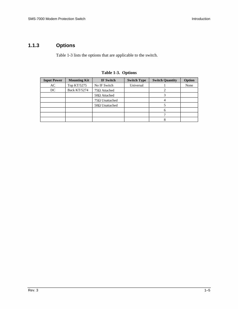
1.1.3 Options
Table 1-3 lists the options that are applicable to the switch.
Table 1-3. Options
Input Power Mounting Kit IF Switch Switch Type Switch Quantity Option
AC Top KT/5275 No IF Switch Universal 1 NoneDC Back KT/5274 75Ω Attached 2
50Ω Attached 3
75Ω Unattached 4
50Ω Unattached 5
678
Introduction SMS-7000 Modem Protection Switch
1–6 Rev. 3
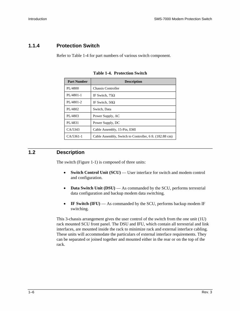
1.1.4 Protection Switch
Refer to Table 1-4 for part numbers of various switch component.
Table 1-4. Protection Switch
Part Number Description
PL/4800 Chassis Controller
PL/4801-1 IF Switch, 75Ω
PL/4801-2 IF Switch, 50Ω
PL/4802 Switch, Data
PL/4803 Power Supply, AC
PL/4831 Power Supply, DC
CA/5343 Cable Assembly, 15-Pin, EMI
CA/5361-1 Cable Assembly, Switch to Controller, 6 ft. (182.88 cm)
1.2 Description
The switch (Figure 1-1) is composed of three units:
• Switch Control Unit (SCU) — User interface for switch and modem controland configuration.
• Data Switch Unit (DSU) — As commanded by the SCU, performs terrestrialdata configuration and backup modem data switching.
• IF Switch (IFU) — As commanded by the SCU, performs backup modem IFswitching.
This 3-chassis arrangement gives the user control of the switch from the one unit (1U)rack mounted SCU front panel. The DSU and IFU, which contain all terrestrial and linkinterfaces, are mounted inside the rack to minimize rack and external interface cabling.These units will accommodate the particulars of external interface requirements. Theycan be separated or joined together and mounted either in the rear or on the top of therack.

SMS-7000 Modem Protection Switch Introduction
Rev. 3 1–7
The switch functional block diagram (Figure 1-2) displays the functional partitioning andinterconnection between the three chassis.
Two cables interconnect the three units. The SCU and DSU are connected via a cablethat transfers power, faults, and switch control between the two chassis. Power, modemfaults, and switch faults originate from the DSU, while switch control commands areinitiated by the SCU. The IFU is connected to the DSU in the same manner.
DATA SW ITCHM:N x8
SLAVECON TROLLER
LO W VO LTAG EPO W ER
LO W VOLTAGEPOW ER
BO Px8
PRIM E POW ER IN
PRIM E POW ER IN
x2 D B50B A C KU P M O D E M D ATAR X /TX
x8 D B50P R IM A RY M O D E M D ATAR X /TX
FR O N T PA N E L
FAU LT A N DS TATU S R E LAY S
C O N TR O LLE RR EM O TE C O NTR O LEIA-485/232
D B 9S W ITC H FA U LTS
x2 D B25O N LIN E S TATU S
D B 9 E IA-485M O D E M R E M O TE
C O N T R O L U N IT
DATA SW ITCH UNIT
FAULTS
EIA-485
IB S/ID R
BALANCED DATAEIA-422G.703V.35EIA-232-C
D B25D B15D B25D B25
UNBALANCED DATA 5 COAXD &IG .703EX TER NA L C LOC K
AU XIL IARY D ATAADPCMESCALARM S
DB9DB25DB25
TER R EST RIALD ATA, x8
SLAVECO NTR OLLER
CO AXSW ITCH
IF S W ITC H UN IT
16 C O AXPRIM ARY M OD EM IFRX/TX
4 CO AXBAC KUP MO D EM IFRX/TX
UP/DO W N LINK16 C O AX
CA/0755
CA/5361
Figure 1-2. Block Diagram

Introduction SMS-7000 Modem Protection Switch
1–8 Rev. 3
1.2.1 Switch Controller Unit (SCU)
The SCU is a one unit (1U), 19-inch (48.26 cm) rack-mounted chassis that provides theconfiguration and automatic switching control functions. Rear panel connectors on thischassis provide all user remote control and status interfaces and rack internal controlinterfaces. The front panel provides local control of the switch.
The SCU front panel (Figure 1-3) provides the user with visual fault and statusindicators. The back-lit display and keypad provide the local user control interface. Thefront panel is a typical Comtech EFData modem front panel status and control interface.The switch front panel supports all functions of the remote port. The user may configureboth the switch and associated modems as well as query status and faults.
Note: The modem control feature is only available with certain modems. Refer to thecompatibility chart (Table 1-3) for specific applications.
Figure 1-3. SCU Front Panel
The SCU rear panel (Figure 1-4) accommodates the user serial command interface forremote configuration and status. These interfaces are also shown in the block diagram(Figure 1-2).
J6 J6 J3 J2 J1J4
PRIME MODSTATUS
PRIME MODSTATUS
SW ITCHFAULTS
MO DEMREMO TE
USERREMO TE
DATA SW ITCHINTER FACE
Figure 1-4. SCU Rear Panel
Prime modulator and demodulator status and switch faults are provided on dedicated I/Oconnectors. Status and fault conditions are indicated at these connectors by opening andclosing relay contacts, which may be used to directly trigger external alarms andindicators. The modem remote port is the control interface to all modems attached to theswitch. The Data Switch Interface, which carries control and fault information betweenthe switch chassis and SCU, is also provided.
SMS-7000 Modem Protection Switch Introduction
Rev. 3 1–9
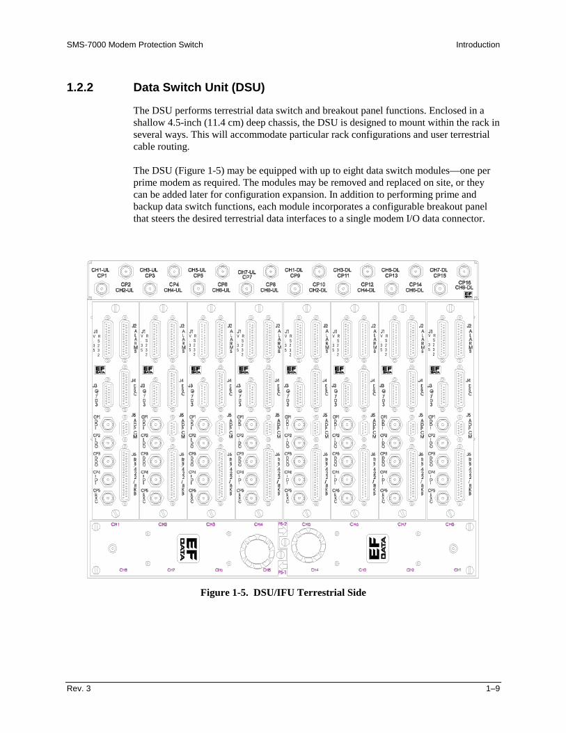
1.2.2 Data Switch Unit (DSU)
The DSU performs terrestrial data switch and breakout panel functions. Enclosed in ashallow 4.5-inch (11.4 cm) deep chassis, the DSU is designed to mount within the rack inseveral ways. This will accommodate particular rack configurations and user terrestrialcable routing.
The DSU (Figure 1-5) may be equipped with up to eight data switch modules—one perprime modem as required. The modules may be removed and replaced on site, or theycan be added later for configuration expansion. In addition to performing prime andbackup data switch functions, each module incorporates a configurable breakout panelthat steers the desired terrestrial data interfaces to a single modem I/O data connector.
V R. S3 25 3
2
V R. S3 25 3
2
V R. S3 25 3
2
V R. S3 25 3
2
V R. S3 25 3
2
V R. S3 25 3
2
V R. S3 25 3
2
V R. S3 25 3
2
Figure 1-5. DSU/IFU Terrestrial Side
Introduction SMS-7000 Modem Protection Switch
1–10 Rev. 3
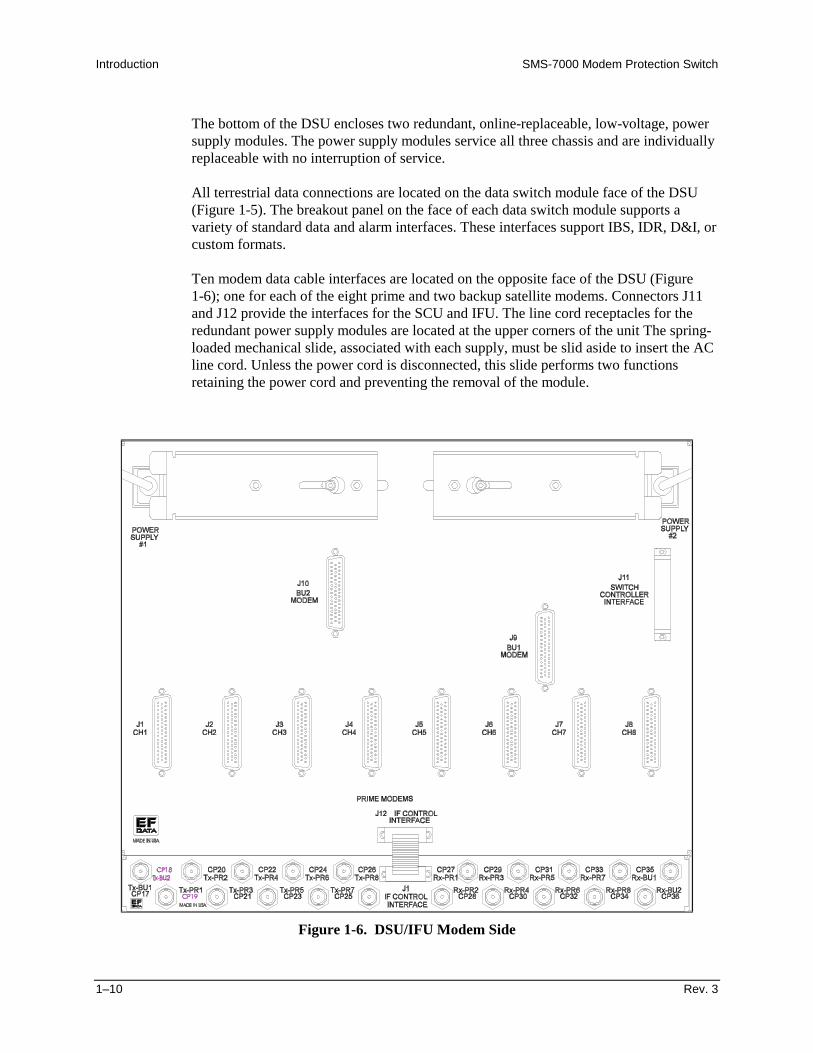
The bottom of the DSU encloses two redundant, online-replaceable, low-voltage, powersupply modules. The power supply modules service all three chassis and are individuallyreplaceable with no interruption of service.
All terrestrial data connections are located on the data switch module face of the DSU(Figure 1-5). The breakout panel on the face of each data switch module supports avariety of standard data and alarm interfaces. These interfaces support IBS, IDR, D&I, orcustom formats.
Ten modem data cable interfaces are located on the opposite face of the DSU (Figure1-6); one for each of the eight prime and two backup satellite modems. Connectors J11and J12 provide the interfaces for the SCU and IFU. The line cord receptacles for theredundant power supply modules are located at the upper corners of the unit The spring-loaded mechanical slide, associated with each supply, must be slid aside to insert the ACline cord. Unless the power cord is disconnected, this slide performs two functionsretaining the power cord and preventing the removal of the module.
Figure 1-6. DSU/IFU Modem Side
SMS-7000 Modem Protection Switch Introduction
Rev. 3 1–11
1.2.3 IF Switch Unit (IFU)
All IF switching is performed in the IFU. In a typical application, the IFU is attached tothe DSU. If necessary, the unit can be mounted separately and interconnected with anextended length interface cable. This procedure is recommended if mounting multipleswitches in the top of a rack or when separate mounting facilitates IF cabling.
The user has access to one downlink and one uplink port for each of the eight channels(Figure 1-5).
Each prime and backup satellite modem in the configuration has an RX and TX coaxialconnection to the modem side of the DSU chassis (Figure 1-6).

Introduction SMS-7000 Modem Protection Switch
1–12 Rev. 3
1.3 Specifications
Refer to Table 1-5 for operating specifications of the switch.
Table 1-5. SMS-7000 Specifications
OperationNumber of Service Channels Modular from 1 to 8. Field upgradeable; one data switch
module per channel.Number of Backups 1 or 2.Switching Modes Auto or Manual.Backup Modes Dependent.
Independent (transmit/receive).Modem Priority Programmable: high, medium, or low.Configuration Control:Remote (programmable):
Type
Rate
Local
EIA-485/232 with provisions for future support of standardnetwork interfaces.
110 to 19200 baud.
Menu-driven from the switch front panel, for both the switchand the modems.
I/O InterfacesControl:Front Panel
Remote
Back-lit LCD display and keypad.
9-pin female D.Front Panel LEDs:
Switch Status
Switch Fault
Modem Fault
Power On.Auto.Manual.
System.Equipment.Stored.
Transmit.Receive.
Monitors:Modulator Online Status
Demodulator Online Status
Switch Faults
FORM-C relay outputs, 25-pin female D.
FORM-C relay outputs, 25-pin female D.
FORM-C relay outputs, 9-pin female D.

SMS-7000 Modem Protection Switch Introduction
Rev. 3 1–13
Table 1-5. SMS-7000 Specifications (Continued)
I/O InterfacesTerrestrial Data(Each channel)
V.35 Data: 25-pin female D.EIA-422/MIL-STD-188 Data: 37-pin female D.G.703 Balanced Drop and Insert: 15-pin female D.G.703 Unbalanced Drop and Insert: Coax.EIA-232 Data: 25-pin female D.ADPCM Audio Data: 9-pin female D.Engineering Data Channel: 25-pin female D.Alarms: 25-pin female D.External Reference Clock: BNC.
IF Ports 10 each IF Modulation: BNC.10 each IF Demodulation: BNC.8 each Uplinks: BNC.8 each Downlinks: BNC.
IF Downlinks: up to 8.Uplinks: up to 8.Frequency response: 50 to 180 MHz.Return loss: 18 dB.Impedance: 75Ω or 50Ω (optional).Isolation: 60 dB.Transmit loss: < 1.5 dB.Receive loss: < 5.0 dB.
GeneralPrime Power 90 to 264 VAC; 47 to 63 Hz, 40W max.
-48 VDC; 40W max. optional.Size and Weight:
Control Unit
Switch Unit with IF Switch
1U 19-inch (48.3 cm) rack mount by 20-inch (51 cm) deep,< 10 lbs. (4.5 kg).
8U 19-inch (48.3 cm) rack mount by approx. 4.5-inch deep(11 cm), < 20 lbs. (9.1 kg).
Mounting Top Mount.Back Mount (Hinged).
Temperature:Operating
Storage
0° to +40ºC (32° to 100°F).
-50° to +100ºC (-58° to 212°F).Humidity 95% at +40ºC (100°F), non-condensing.EMI CE-Mark certified.

Introduction SMS-7000 Modem Protection Switch
1–14 Rev. 3
This page is intentionally left blank.
Rev. 3 2–1
2Chapter 2. INSTALLATION
This chapter provides instructions for unpacking and installation, as well as externalconnection information for the switch.
2.1 Unpacking
The switch (which consists of three sections) and the manual are packaged in pre-formed, reusable, cardboard cartons that contain foam spacing for maximum shippingprotection.
CAUTION
Do not use any cutting tool that will extend more than 1 inch (2.5 cm) intothe container and cause damage to the switch.
To remove the switch:
1. Cut the tape at the top of the carton (indicated by OPEN THIS END).
2. Remove the cardboard/foam packing covering the switch.
3. Remove the switch components, product manual, and power cords from thecarton.
4. Save the packing material for storage or reshipment purposes.
5. Inspect the equipment for any possible damage incurred during shipment.
6. Check the equipment against the packing list to ensure the shipment is correct.

Installation SMS-7000 Modem Protection Switch
2–2 Rev. 3
2.2 Equipment Inspection
2.2.1 Included Parts
A typical switch contains the following components:
Note: Parts are not drawn to scale.
Qty Description Qty Description1 SMS-7000 Switch 1 Installation and Operation Manual
1 Cable Assembly, 37-Pin
Comtech EFData Part # PL/5361-X
1 Envelope containing the test data
1 Cable Assembly, 15-pin M-15 pin
Comtech EFData Part No.CA/5343-X

SMS-7000 Modem Protection Switch Installation
Rev. 3 2–3
2.2.2 Back Mount (Hinged) Hardware Kit
1 Back Mount (Hinged) Hardware Kit (Comtech EFData Part # KT/5274), which includes:Qty Description Qty Description1 Base Hinge
Comtech EFData Part # FP/5151
8 10-32 x 1/2 Socket Head Cap Screws
Comtech EFData Part # HW/10-32X1/2SH
1 Plate, Hinge Mounting
Comtech EFData Part # FP/5152-1
8 #10 Flat Washer
Comtech EFData HW/10-FLT1 Plate, Hinge Mounting
Comtech EFData Part # FP/5152-2
4 10-32 x 3/8 Phillips Screw
Comtech EFData Part # HW/10-32X3/8 P.H.1 Panel, Hinge Latch
Comtech EFData Part # FP/5153
2 Latch, Slam, 1/4 Turn, Black Knob
Comtech EFData Part # LATCH04
2 Plate, Latch Striker
Comtech EFData Part # 5154
4 Spacer, 0.380 ID x 0.062 Thick, Fiber
Comtech EFData Part # SPC380F0621 Back Mount (Hinged) Hardware Kit (Comtech EFData Part # KT/5274), which includes:
Qty Description Qty Description4 1/4-20 x 1/4 Socket Head Shoulder Screw
Comtech EFData Part #HW/1/4-20X1/4SHSS
Installation SMS-7000 Modem Protection Switch
2–4 Rev. 3
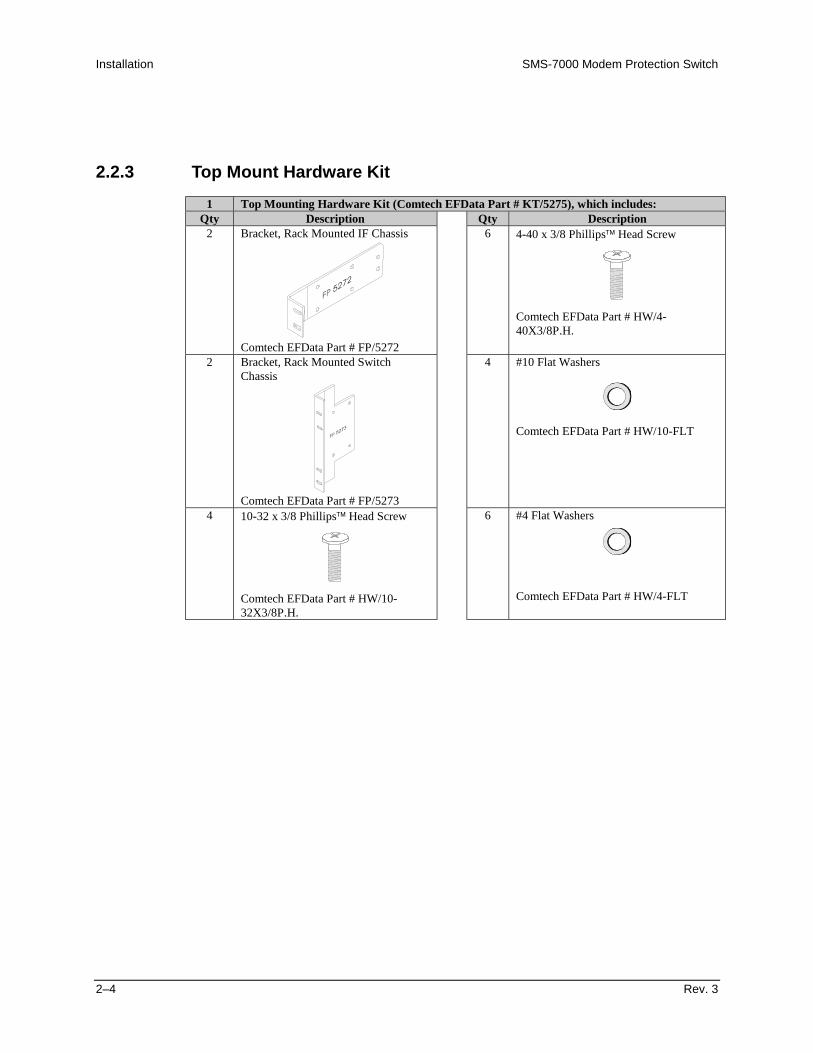
2.2.3 Top Mount Hardware Kit
1 Top Mounting Hardware Kit (Comtech EFData Part # KT/5275), which includes:Qty Description Qty Description
2 Bracket, Rack Mounted IF Chassis
Comtech EFData Part # FP/5272
6 4-40 x 3/8 Phillips Head Screw
Comtech EFData Part # HW/4-40X3/8P.H.
2 Bracket, Rack Mounted SwitchChassis
Comtech EFData Part # FP/5273
4 #10 Flat Washers
Comtech EFData Part # HW/10-FLT
4 10-32 x 3/8 Phillips Head Screw
Comtech EFData Part # HW/10-32X3/8P.H.
6 #4 Flat Washers
Comtech EFData Part # HW/4-FLT
SMS-7000 Modem Protection Switch Installation
Rev. 3 2–5
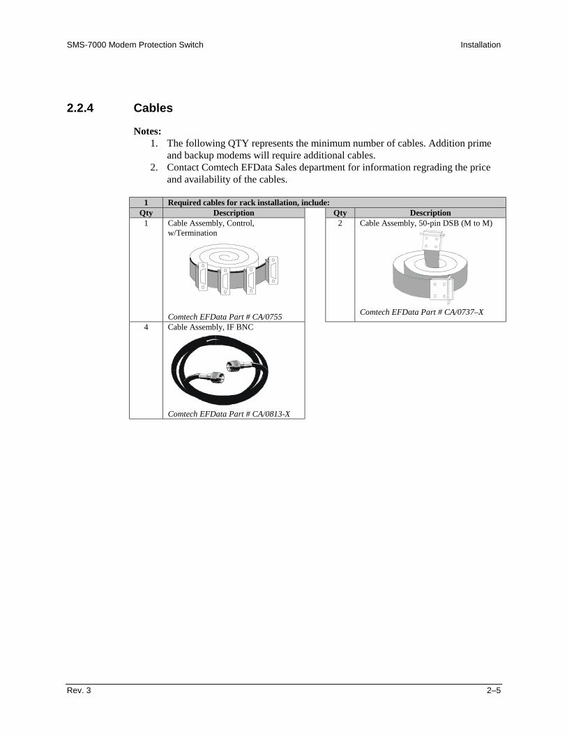
2.2.4 Cables
Notes:1. The following QTY represents the minimum number of cables. Addition prime
and backup modems will require additional cables.2. Contact Comtech EFData Sales department for information regrading the price
and availability of the cables.
1 Required cables for rack installation, include:Qty Description Qty Description
1 Cable Assembly, Control,w/Termination
Comtech EFData Part # CA/0755
2 Cable Assembly, 50-pin DSB (M to M)
Comtech EFData Part # CA/0737–X
4 Cable Assembly, IF BNC
Comtech EFData Part # CA/0813-X

Installation SMS-7000 Modem Protection Switch
2–6 Rev. 3
2.2.5 Tools Required
Qty Description1
1
1
1
1
3/8 inch (9 mm) drive ratchet.
3 x 3/8 inch (76 x 9 mm) drive extension.
1/2 x 3/8 inch drive socket. (Metric equivalent: 13mm,6 pt.)
3/8 x 3/8 inch drive socket. (Metric equivalent:9mm, 6 pt.)
1/4 x 3/8 inch drive socket. (Metric equivalent:6mm, 6 pt.)
1 1/2 inch combination wrench. (Metric equivalent:13mm combination wrench with a 6 pt. box end.)

SMS-7000 Modem Protection Switch Installation
Rev. 3 2–7
2.3 Mounting
Prior to installing the switch in the customer equipment rack, an appropriate mountingconfiguration must be defined. The switch components are designed for a variety ofmounting options to accommodate different user requirements.
The Switch Control Unit (SCU) chassis is a one unit (1U), 19-inch (48.3 cm) rack-mountable unit intended for mounting at eye level in the front of the rack. The keypadand display on the front panel of the SCU provide single-point control for all modemsassociated with the switch, as well as for the switch.
The Data Switch Unit (DSU) and IF Unit (IFU) chassis may be mounted in various ways.User application requirements determine which rack mounting option is used. The twobasic mounting locations are:
• Top mount• Back mount
2.3.1 Description
2.3.1.1 Top Mount
This installation is intended for ceiling-routed cables, where terrestrial data harnessesconveniently enter from the top of the rack. Installed on standard 19-inch (48.3 cm) railsthrough an opening in the top of the rack, with the terrestrial interfaces facing up, thisconfiguration provides direct access to terrestrial data and IF ports at the top of the rack,minimizing cabling within the rack.
2.3.1.2 Back Mount
This installation is intended for configurations where terrestrial data cables enter the topand/or bottom of the rack. A back mount (hinge) kit is used to facilitate installation andservice access. The DSU and IFU are mounted directly inside the rear door of the rack.The hinged switch chassis, when pitched out at the rear of the rack, provides access toboth the rear of the front panel-mounted equipment and the inside face of the switch.
Installation SMS-7000 Modem Protection Switch
2–8 Rev. 3
2.3.2 Installation
2.3.2.1 Switch Control Unit
The Switch Control Unit (SCU) arrives fully assembled from the factory. Afterunpacking the switch, install the switch control unit into the equipment rack and securewith customer-furnished hardware.
2.3.2.2 Top Mount Installation
The Top Mount Hardware Kit (KT/5275) is for fixed-mounting the Data Switch Unit(DSU) and Intermediate Frequency Switch Unit (IFU) to a standard equipment rack rails.Kit components are listed in Section 2.2.
Although top mounting can be employed wherever there is clearance within the rack, itprovides a convenient external rack interface for both terrestrial data and IF signals thatare routed from the ceiling.
Assemble the DSU and IFU as shown in Figure 2-1 and as follows:
1. Install Bracket (FP/5272) on the IFU and secure with 6 screws and flat washers.
2. Install Bracket (FP/5273) onto the DSU and secure with 8 screws and flatwashers.
3. Position unit into the rack and secure with customer-furnished hardware.

SMS-7000 Modem Protection Switch Installation
Rev. 3 2–9
Figure 2-1. Top Mount Installation

Installation SMS-7000 Modem Protection Switch
2–10 Rev. 3
2.3.2.3 Back Mount Installation
The back mount (hinge) feature provides ready access for installation and service, whilemaking efficient use of rack volume. The Back-Mount Hardware Kit (KT/5274) isintended for (but not restricted to) use in rear-mount applications where clearance andaccess might create difficulty. Kit components are listed in Section 2.2.
The DSU and IFU must be secured prior to installation into the equipment rack. Thehinge is mounted to the attached base plate of the DSU). The latch plates are mounted tothe attached base plate. The DSU can be directly mounted behind the SCU and theprime, and backup modems that it services.
Note: This mounting requires the use of right-angle backshells for both the modem andterrestrial data cables.
Assemble the DSU and IFU as shown in and as follows:
1. Position IFU on DSU and secure with four Phillips screws.
2. Install the Top Plate (FP/5153) to the IFU and secure with four 1/2-inch socketscrews and flat washers.
3. Install plates (FP/5154) to the equipment rack at the level to connect to the topplate and secure with customer-furnished hardware.
4. Install base plate to the DSU and secure with four 1/2-inch socket screws and flatwashers.
5. Install right Plate (FP/5152-1) to the base plate and secure with two socketscrews and spacers.
6. Install left Plate (FP/5152-2) to the base plate and secure with two socket screwsand spacers.
7. Install the assembled DSU and IFU to the equipment rack and secure withcustomer-furnished hardware.

SMS-7000 Modem Protection Switch Installation
Rev. 3 2–11
Figure 2-2. Back Mount (Hinge) Installation
Installation SMS-7000 Modem Protection Switch
2–12 Rev. 3
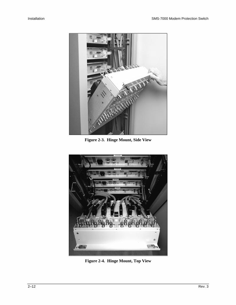
Figure 2-3. Hinge Mount, Side View
Figure 2-4. Hinge Mount, Top View

SMS-7000 Modem Protection Switch Installation
Rev. 3 2–13
2.4 Cable Installation
2.4.1 Interconnecting the Switch Components
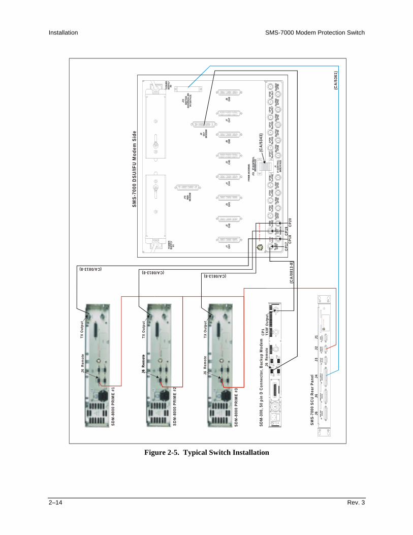
Refer to Error! Reference source not found. for typical cable installation.
The equipment rack is a mixed rack consisting of a SDM-6000 Satellite Modem servingas the prime and a SDM-300 Satellite Modem incorporating the 50-pin data interface,serving as the backup modem.
The SMS-7000 Switch is provided with two cables. All other cables are optional and thecustomer should contact Comtech EFData Customer Support for price and availability.
Installation SMS-7000 Modem Protection Switch
2–14 Rev. 3
ADA
PTIV
E B
ROA
DB
AND
TM
J6 RE
MO
TE
AL
AR
MS
J10
FAU
LT J7J
9A
UX
1E
XR
EF
RX
/IFIN
PU
T
CP
3C
P1
CP
2
TX
/IF
OU
TP
UT
SD
M-8
000
PR
IME
#1
SD
M-8
000
PR
IME
#2
SD
M-8
000
PR
IME
#3
SM
S-7
000
SC
U R
ear
Pan
el
SD
M-3
00, 5
0 p
in D
Co
nn
ecto
r, B
acku
p M
od
em
J6J6
J4J3
J2J1
J6 R
emo
te
J6 R
emo
te
J6 R
emo
te
J6 R
emo
te
J6 R
emo
te
CP
1
TX
/IF O
utp
ut
TX
Ou
tpu
t
TX
Ou
tpu
t
TX
Ou
tpu
t
ADAPTIV
E BR
OAD
BAN
DT
M
SM
S-7
000
DS
U/IF
U M
od
em S
ide
(CA
/536
1)
(CA
/534
3)(CA/0813-8)
(CA/0813-8)(CA/0813-8)
(CA
/081
3-8)
CP
20C
P19
CP
17C
P18
Figure 2-5. Typical Switch Installation

SMS-7000 Modem Protection Switch Installation
Rev. 3 2–15
2.4.1.1 SCU (J4) to DSU (J11) Interface
Refer to Figure 2-5.
Cable Assembly Part No. CA/5361 is provide with the switch. This is a single cableinterface between SCU Data Switch Interface J4 connector to the DSU Switch ControllerInterface J11 connector. The cable carries modem alarms, power supply faults, the serialcommand link, and SCU power.
2.4.1.2 Remote Connection
Refer to Figure 2-5.
Option - Cable Assembly Part No. CA/0755 is offered by Comtech EFData. The remoteserial interface J6 connector of each modem in the configuration is bussed to the SCUModem Remote J2 connector.
This cable is a 9-pin D EIA-485 2-wire ribbon cable and must be connected beforeprogramming the switch configuration. The cable assembly is configured for:
• Baud Rate: 9.6 to 19.2K• 7 Information bits• Parity: Even• 2 Stop bits
Note: Ensure the modems are all set to EIA-485 2-wire and that the baud rates match.
The ribbon cable assembly is used to query the configuration of modems, to set theconfiguration of the backup modem, and to verify the saved configuration of themodems. This data is used by the switch controller to set the position of the relays in thedata modules.

Installation SMS-7000 Modem Protection Switch
2–16 Rev. 3
2.4.1.3 DSU (J12) to IFU (J1)
Refer to Figure 2-5.
Cable Assembly Part No. CA/5343 is provided with the switch. This is a single cableinterface between the two switching sections, J12 IF Control Interface on the DSU andJ1 IF Control Interface on the IFU. The cable carries EIA-485 at 9600 baud, controlsignals, and power.
2.4.1.4 DSU J9 (BU1) Modem Connector to Backup Modem
Refer to Figure 2-5.
Option – Cable Part No. CA/0737 is offered by Comtech EFData. This 50-pin cable isavailable in either straight hoods or right angle hoods. Refer to Table 2-1. This cableincludes two faults, Mod and Demod, pins 49 and 33. The modems will ground the twopins when a No Fault condition exists. When either a Mod or Demod fault occurs, a linewill either Open, with the 50-pin cable pulled Off, or +5 VDC that is allowed from theopen collector fault circuit on the modem.
Table 2-1. 50-Pin Cable
Part No. Length, ft TypeCA/0737-2 2 StraightCA/0737-4 4 StraightCA/0737-4R 4 Right AngleCA/0737-6 6 StraightCA/0737-6R 6 Right AngleCA/0737-8 8 StraightCA/0737-8R 8 Right AngleCA/0737-10 10 Straight
2.4.1.5 DSU JI CH to Prime Modem
Refer to Figure 2-5.
Option – Cable Part No. CA/0737 is offered by Comtech EFData.

SMS-7000 Modem Protection Switch Installation
Rev. 3 2–17
2.4.1.6 IFU Connections (CP17 through CP36)
Refer to Figure 2-5.
Option – Cable CA/0813-8 is offered by Comtech EFData. Each prime and backupmodem in the configuration has an RX and TX coaxial connection to the modem face ofthe IFU chassis. The switch and modems should have compatible characteristic IFimpedances of either 75Ω or 50Ω. Miniature coax is recommended to facilitateharnessing.
2.5 Configuration Setup
This procedure will apply to the SDM-300, and current versions of the SDM-6000 andSDM-8000 modems.
Note: Communications shall be established between the switch controller and themodems. No visual activity will occur, however, relays may click and fault lamps maycome on. Use UTILITY/MODEM CONTROL to take command of the operation.
2.5.1 Configure Rack Setup
Note: The EIA-485 bus on the ribbon cable will be frozen if any communications are setto EIA-232.
1. Check each modem for the following:
a. Remote Baud Rate: 9.6 or 19.2 kbit/sb. Ribbon Cable: EIA-485 (2- or 4-wire)c. Remote Address: Note
2. Check IF switch for the following:
a. Modem Remote Baud Rate: 9.6 or 19.2 kbit/sb. Remote Address: Config the prime and backup modem to match.

Installation SMS-7000 Modem Protection Switch
2–18 Rev. 3
3. Configure the switch controller, prime, and backup modems as follows:
a. Go to CONFIG/BACKUP #1 and insert all parameters.
Notes:• DEPENDENT switching is preferred and it is the only function to
operate in the Drop and Insert application.• The screen showing underlines will have to be filled in for the specific
modems that are to be backed up.• If a modem in the switch is required, but not to be backed up, then leave
field blank.• Turn MOD and DEMOD off on each prime modem, if the back up
modem is not to emulate the prime modem. The switch controller willignore the faults from the modem.
b. Configure the prime modems.
c. If Drop and Insert is the applications, then use Insert Clock as the RX Buffer.Select LOOP that states; INSERT DATA INPUT LOOP or NORMAL.Balance is for G.703 data cables that have different pairs.
d. Set LOAD ALL MODEMS. Fault lamps should go off.
4. Set switch mode from OPERATION to AUTO.
5. Backup modem should go into REMOTE.
6. Set switch screen to SYSTEM STATUS/SWITCHING.
7. Test the configured protection system as follows:
a. Crisscross the IF inputs on two prime modems.
b. Ensure the two modems transfer data to each other in the protection system.
c. Turn off the SDM-7000 switch to change data modules. If not, re-initialization of the switch controller may result.

SMS-7000 Modem Protection Switch Installation
Rev. 3 2–19
2.5.2 Trouble Shoot Configuration
Refer to Table 2-2 for trouble shooting information.
Table 2-2. Trouble Shooting
Problem Possible Cause RemedyLoad comes up with a MOD or DEMODconfiguration error.
1. Switch controller notcommunicating to the modems.
2. Backup modem cannot match allthe commands as the prime mode.
Switch controller will query the modemswith a MCP and DCP command. Datawill be stored and compared with backupmodem. If no match, perform thefollowing:
1. Rack contains mixed modems. Onemodem is high power and one isnormal power out. Set modems to≤ –5 dBm .
2. Software version numbers are notcompatible. Upgrade the firmwareas necessary.
3. SDM-8000 is emulating anSDM-6000 and SDM-300emulating an SDM-6000.Reconfigure rack with specificmodems. (SDM-8000 will backupan SDM-6000, and the SDM-300will backup SDM-300 modem.)
4. Ensure communications to themodem are operational.
A flashing number and the letter ‘F’appears.
Reporting an open cable and is reportinga fault.
Backup modem will indicate a ‘B’ andeither a –, *, or ↑.
The – indicates; Backup modem is readyto take command for a specific modem.The * indicates; Backup modem isundergoing remote configuration.The ↑ indicates; Backup modem hastaken command for a specific primemode.

Installation SMS-7000 Modem Protection Switch
2–20 Rev. 3
2.6 DSU Data Connections (J1 through J10)
There are 10 data cables between the modem face of the DSU and 10 possible modemsassociated with the switch. Each of the eight prime modems has an associated data cableconnector, CH1 through CH8 (J1 through J8). The two backup modems are connectedwith data cables to BU1 and BU2 (J9 and J10). The cable terminations are 50-pin male Dconnectors. The signal/pin assignments, as they occur for each data configuration, arelisted in Table 2-3.
Table 2-3. DSU Data Connections (J1 through J10)
Signal NameOverhead Type SDM-100 and No Overhead
Pin # IBS IDR D&I EIA-422 V.35 EIA-2321 GND GND GND GND GND GND2 GND GND GND3 AGC-OUT AGC-OUT AGC-OUT4 TXD-B 8K-TXO-A5 TXD-A 8K-TXO-B6 RXD-B 8K-RXO-A7 RXD-A 8K-RXO-B8 RS422RXO-A BWO1-C9 RS422RXO-B BWO2-C10 PRI-COM BWO3-C11 SEC-COM BWO4-C12 SCTE/TT-A BWI-1 TT-A SCTE-A TT13 SCTE/TT-B BWI-2 TT-B SCTE-B14 RS422TXO-A BWI-315 RS422TXO-B BWI-416 DF-COM17 DMA18 G703_SDB SD-B DDI-B19 EXC-B EXC-B EXC_B EXC-B EXC-B20 G703_RDB RD-B IDO-B21 SCT/ST-A 8K-TXC-A ST-A SCT A ST22 SCT/ST-B 8K-TXC-B ST-B SCT B

SMS-7000 Modem Protection Switch Installation
Rev. 3 2–21
Table 2–3. DSU Data Connections (J1 through J10) (Continued)
Signal NameOverhead Type SDM-100 and No Overhead
Pin # IBS IDR D&I EIA-422 V.35 EIA-23223 SCR/RT-A 8K-RXC-A RT-A SCRA RT24 SCR/RT-B 8K-RXC-B RT-B SCRB25 TXCK BWO1-NC26 RXCK BWO2-NC27 PRI-NC BWO3-NC28 SEC-NC BWO4-NC29 RTS-B A1I-B RTS-B30 RR-B A1O-B RR-B31 CTS-B A2I-B CTS-B32 DM-B A2O-B DM-B33 DMD-FLT DMD-FLT DMD-FLT34 G703_SDA SD-A DDI-A35 EXC-A EXC-A EXC_A EXC-A EXC-A EXT CLK36 G703_RDA RD-A IDO-A37 SD-A 8K-TXD-A DDO-A SDA SD-A SD38 SD-B 8K-TXD-B DDO-B SDB SD-B39 RD-A 8K-RXD-A IDI-A RDA RD-A RD40 RD-B 8K-RXD-B IDI-B RD-B RD-B41 DSR/DM-A BWO1-NO42 BWO2-NO43 PRI-NO BWO3-NO44 SEC-NO BWO4-NO45 RTS-A A1I-A RTS-A RTS RTS46 RLSD/RR-A A1O-A RR-A RLSD RR47 CTS-A A2I-A CTS-A CTS CTS48 DSR/DM-A A2O-A DM-A DSR DM49 MOD-FLT MOD-FLT MOD-FLT50 DF-NO
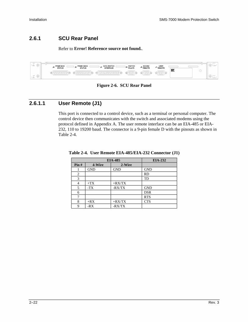
Installation SMS-7000 Modem Protection Switch
2–22 Rev. 3
2.6.1 SCU Rear Panel
Refer to Error! Reference source not found..
Figure 2-6. SCU Rear Panel
2.6.1.1 User Remote (J1)
This port is connected to a control device, such as a terminal or personal computer. Thecontrol device then communicates with the switch and associated modems using theprotocol defined in Appendix A. The user remote interface can be an EIA-485 or EIA-232, 110 to 19200 baud. The connector is a 9-pin female D with the pinouts as shown inTable 2-4.
Table 2-4. User Remote EIA-485/EIA-232 Connector (J1)
EIA-485 EIA-232Pin # 4-Wire 2-Wire
1 GND GND GND2 RD3 TD4 +TX +RX/TX5 -TX -RX/TX GND6 DSR7 RTS8 +RX +RX/TX CTS9 -RX -RX/TX

SMS-7000 Modem Protection Switch Installation
Rev. 3 2–23
2.6.1.2 Modem Remote (J2)
The modem remote interface is a 2-wire EIA-485, 9600, or 19200 baud. The connector isa 9-pin female D, with the pinouts as shown in Table 2-5.
Table 2-5. Modem Remote EIA-485 Connector (J2)
Pin # Signal Name1 GND2 Unused3 Unused4 +RX/TX5 -RX/TX6 Unused7 Unused8 +RX/TX9 -RX/TX
2.6.1.3 Switch Faults (J3)
Switch fault outputs on this connector are provided by Form C relay contacts for statusmonitoring.
• Controller Fault is indicated by a Common-to-Normally Closed contact closure,activated if the controller loses power.
• M:N faults are indicated by a Common-to-Normally Open contact closure,activated in the event of any fault registered in the Fault Alarm Menus.
Maximum relay contact current is 1A at 30 VDC.
The connector is a 9-pin female D with the pinouts as shown in Table 2-6.
Table 2-6. Switch Faults Connector (J3)
Pin # Signal Name1 Controller Fault NO2 Controller Fault COM3 Controller Fault NC4 M:N Fault NO5 M:N Fault COM6 M:N Fault NC7 Spare 2 NO8 Spare 2 COM9 Spare 2 NC
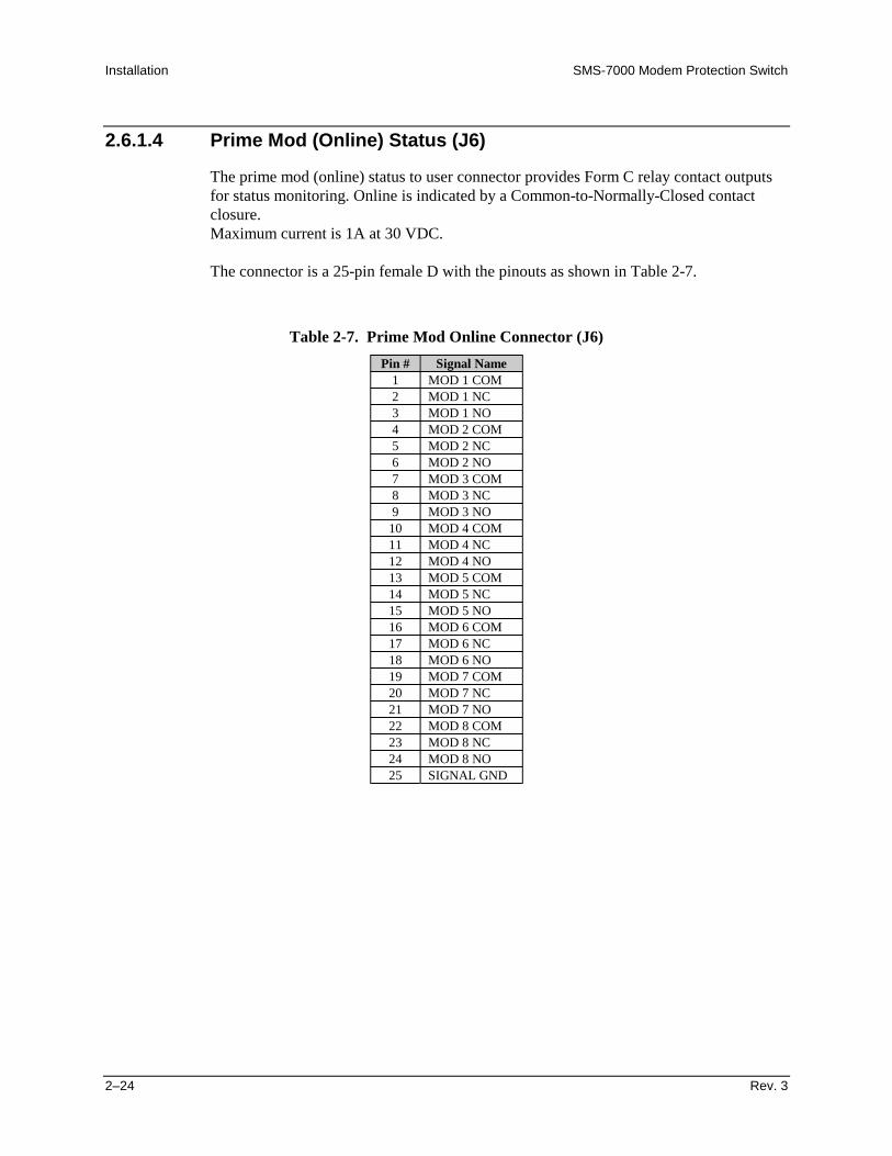
Installation SMS-7000 Modem Protection Switch
2–24 Rev. 3
2.6.1.4 Prime Mod (Online) Status (J6)
The prime mod (online) status to user connector provides Form C relay contact outputsfor status monitoring. Online is indicated by a Common-to-Normally-Closed contactclosure.Maximum current is 1A at 30 VDC.
The connector is a 25-pin female D with the pinouts as shown in Table 2-7.
Table 2-7. Prime Mod Online Connector (J6)
Pin # Signal Name1 MOD 1 COM2 MOD 1 NC3 MOD 1 NO4 MOD 2 COM5 MOD 2 NC6 MOD 2 NO7 MOD 3 COM8 MOD 3 NC9 MOD 3 NO
10 MOD 4 COM11 MOD 4 NC12 MOD 4 NO13 MOD 5 COM14 MOD 5 NC15 MOD 5 NO16 MOD 6 COM17 MOD 6 NC18 MOD 6 NO19 MOD 7 COM20 MOD 7 NC21 MOD 7 NO22 MOD 8 COM23 MOD 8 NC24 MOD 8 NO25 SIGNAL GND

SMS-7000 Modem Protection Switch Installation
Rev. 3 2–25
2.6.1.5 Prime Mod (Online) Status (J5)
The prime mod (online) status to user connector provides Form C relay contact outputsfor status monitoring. Online is indicated by a Common-to-Normally Closed contactclosure. Maximum current is 1A at 30 VDC.
The connector is a 25-pin female D with the pinouts as shown in Table 2-8.
Table 2-8. Prime Demod Online Connector (J5)
Pin # Signal Name1 DMD 1 COM2 DMD 1 NC3 DMD 1 NO4 DMD 2 COM5 DMD 2 NC6 DMD 2 NO7 DMD 3 COM8 DMD 3 NC9 DMD 3 NO
10 DMD 4 COM11 DMD 4 NC12 DMD 4 NO13 DMD 5 COM14 DMD 5 NC15 DMD 5 NO16 DMD 6 COM17 DMD 6 NC18 DMD 6 NO19 DMD 7 COM20 DMD 7 COM21 DMD 7 NO22 DMD 8 COM23 DMD 8 NC24 DMD 8 NO25 SIGNAL GND

Installation SMS-7000 Modem Protection Switch
2–26 Rev. 3
2.6.2 DSU Terrestrial Data Interfaces
Refer to Figure 2-7.
Up to eight switch modules support the following terrestrial data interfaces.
V R. S3 25 3
2
V R. S3 25 3
2
V R. S3 25 3
2
V R. S3 25 3
2
V R. S3 25 3
2
V R. S3 25 3
2
V R. S3 25 3
2
V R. S3 25 3
2
Figure 2-7. DSU/IFU Terrestrial Side

SMS-7000 Modem Protection Switch Installation
Rev. 3 2–27
2.6.2.1 EIA-422/8 kbit/s Terrestrial Data (J6)
This data port is used for IBS-422 terrestrial data or IDR 8 kbit/s terrestrial overheaddata. The connector is a 37-pin female D, with one connector per channel (Table 2-9).
CAUTION
When using this port for IBS or no overhead data, be certain there is noconnection to the J1 (V.35) or J3 (G.703) ports. When using EIA-422 data,all data switch modules must have jumper JP1 in EIA-422 position (withjumpers connecting the middle pin and the pin closest to the front of theswitch module).
Table 2-9. EIA-422 Terrestrial Data Connectors (J6)
Signal NamePin # IBS IDR D&I
1 SHIELD SHIELD23 RS422 TXO-A 8K TXO A4 SD A 8K TXD A5 ST A 8K TXC A6 RD A 8K RXD A C7 RTS A RTS A A8 RT A 8K RXC A B9 CTS A CTS A L
10 E11 DM A N/C12 R13 RR A N/C E14 M15 EXC A 8K RXO A O16 RS422 RXO A N/C V17 TT A N/C E18 D19 GND GND20 GND GND21 RS422 TXO-B 8K TXO B

Installation SMS-7000 Modem Protection Switch
2–28 Rev. 3
Table 2–9. EIA-422 Terrestrial Data Connectors (J6) (Continued)
Signal NamePin # IBS IDR D&I
22 SD B 8K TXD B23 ST B 8K TXC B24 RD B 8K RXD B25 RTS B RTS B A26 RT B 8K RXC B L27 CTS B CTS B2829 DM B N/C3031 RR B N/C3233 EXC B 8K RXO B34 RS422 RXO B N/C35 TT B N/C3637 GND GND

SMS-7000 Modem Protection Switch Installation
Rev. 3 2–29
2.6.2.2 V.35/EIA-232-C Terrestrial Data (J1)
The V.35 terrestrial data connector (one of three IBS data options) is a 25-pin female D,with one connector per channel (refer to Table 2-10).
CAUTION
When using this port, be certain there is no connection to the J6 (EIA-422)or J3 (G.703) ports. When using EIA-232 data, all data switch modulesmust have jumper JP1 in EIA-232 position (with jumpers connecting themiddle pin and the pin furthest from the front of the switch module). ForV.35, all jumpers must be in EIA-422 position.
Table 2-10. V.35/EIA-232 Terrestrial Data Connectors (J1)
Signal NamePin # IBS V.35 IDR D&I EIA-232-C
1 SHIELD SHIELD2 SD A SD3 RD A RD4 RTS C C RTS5 CTS A A CTS6 DSR B B DM7 SIG GND L L SIG GND8 RLSD E E RR9 SCR B EXT CLK
1011 SCTE B12 SCT B R R13 E E14 SD B M M15 SCT A O O ST16 RD B V V17 SCR A E E RT18 D D1920 EXC A212223 EXC B24 SCTE A (TT)25 A
Note: For all eight switch modules, JP1 must be either set all EIA-232 or allEIA-422/V.35/G.703 (JP1 set in the EIA-422/V.35/G.703 position works for mostapplications).
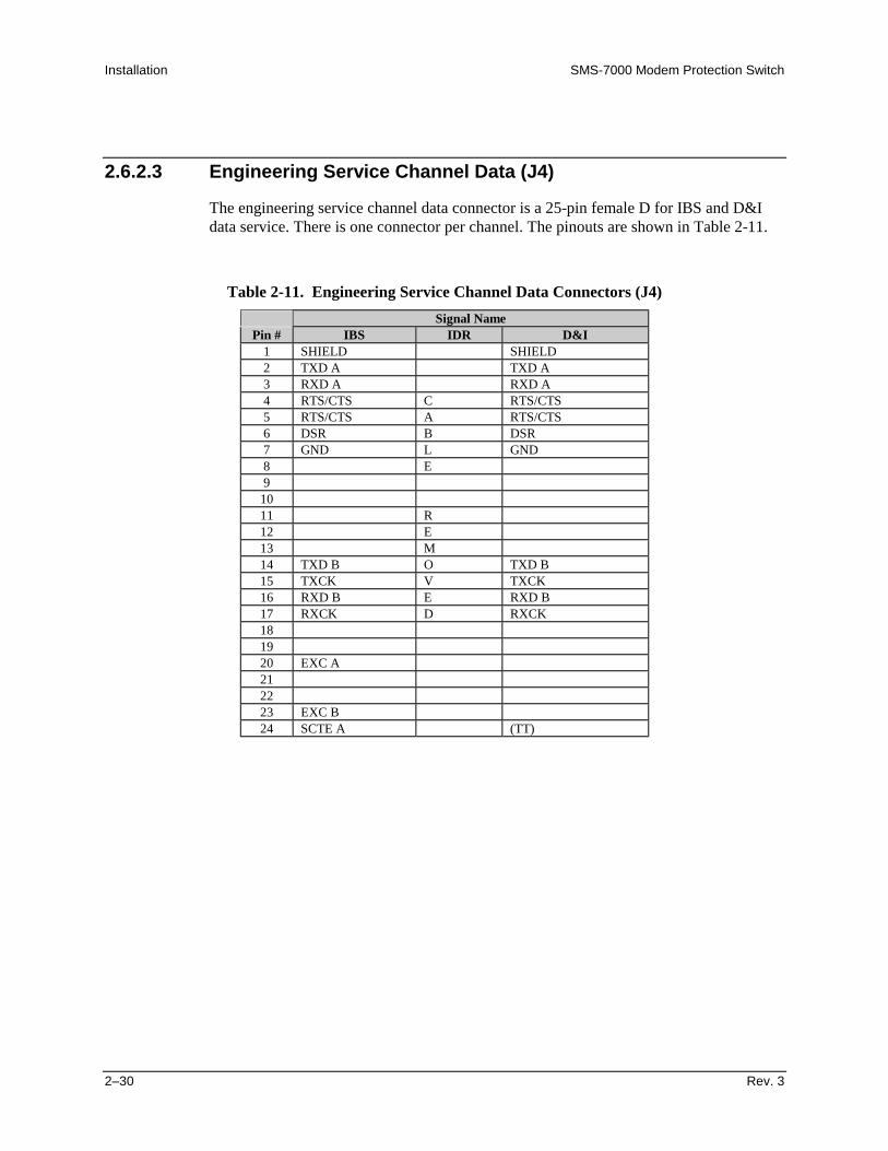
Installation SMS-7000 Modem Protection Switch
2–30 Rev. 3
2.6.2.3 Engineering Service Channel Data (J4)
The engineering service channel data connector is a 25-pin female D for IBS and D&Idata service. There is one connector per channel. The pinouts are shown in Table 2-11.
Table 2-11. Engineering Service Channel Data Connectors (J4)
Signal NamePin # IBS IDR D&I
1 SHIELD SHIELD2 TXD A TXD A3 RXD A RXD A4 RTS/CTS C RTS/CTS5 RTS/CTS A RTS/CTS6 DSR B DSR7 GND L GND8 E9
1011 R12 E13 M14 TXD B O TXD B15 TXCK V TXCK16 RXD B E RXD B17 RXCK D RXCK181920 EXC A212223 EXC B24 SCTE A (TT)

SMS-7000 Modem Protection Switch Installation
Rev. 3 2–31
2.6.2.4 Alarms (J2)
The Alarms (J2) interface accommodates alarms as defined by IBS, IDR, and D&I dataformats. A relative demodulator signal strength (AGC_OUT) is also provided on thisconnector. The alarms connector is a 25-pin female D with one connector per channel.The pinouts are shown in Table 2-12.
Table 2-12. Alarms (J2) Connectors
Signal NamePin # IBS IDR D&I
1 N/C N/C N/C2 N/C BWO1 C N/C3 N/C BWO1 NC N/C4 N/C BWO2 NO N/C5 PROMPT COM BWO3 C PROMPT COM6 PROMPT NC BWO3 NC PROMPT NC7 SERVICE NO BWO4 NO SERVICE NO8 N/C DF COM N/C9 N/C DMA N/C
10 N/C BWI 2 N/C11 N/C BWI 4 N/C12 N/C N/C N/C13 AGC_OUT AGC_OUT AGC_OUT14 GND GND GND15 N/C BWO1 NO N/C16 N/C BWO2 C N/C17 N/C BWO2 NC N/C18 PROMPT NO BWO3 NO PROMPT NO19 SERVICE COM BWO4 C SERVICE COM20 SERVICE NC BWO4 NC SERVICE NC21 N/C DF NO N/C22 N/C BWI 1 N/C23 N/C BWI 3 N/C24 N/C N/C N/C25 GND GND GND26 RT B 8K RXC B L27 CTS B CTS B
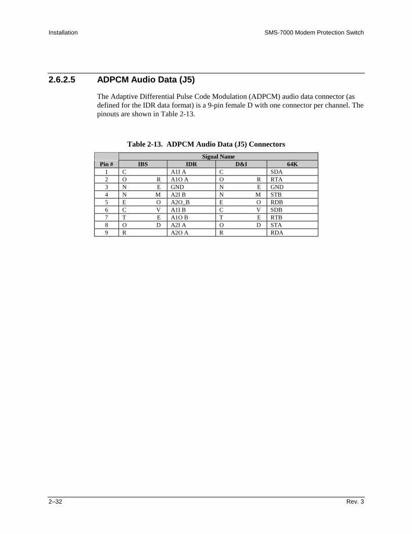
Installation SMS-7000 Modem Protection Switch
2–32 Rev. 3
2.6.2.5 ADPCM Audio Data (J5)
The Adaptive Differential Pulse Code Modulation (ADPCM) audio data connector (asdefined for the IDR data format) is a 9-pin female D with one connector per channel. Thepinouts are shown in Table 2-13.
Table 2-13. ADPCM Audio Data (J5) Connectors
Signal NamePin # IBS IDR D&I 64K
1 C A1I A C SDA2 O R A1O A O R RTA3 N E GND N E GND4 N M A2I B N M STB5 E O A2O_B E O RDB6 C V A1I B C V SDB7 T E A1O B T E RTB8 O D A2I A O D STA9 R A2O A R RDA
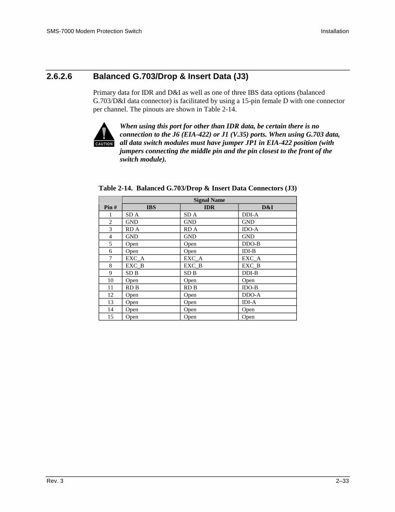
SMS-7000 Modem Protection Switch Installation
Rev. 3 2–33
2.6.2.6 Balanced G.703/Drop & Insert Data (J3)
Primary data for IDR and D&I as well as one of three IBS data options (balancedG.703/D&I data connector) is facilitated by using a 15-pin female D with one connectorper channel. The pinouts are shown in Table 2-14.
CAUTION
When using this port for other than IDR data, be certain there is noconnection to the J6 (EIA-422) or J1 (V.35) ports. When using G.703 data,all data switch modules must have jumper JP1 in EIA-422 position (withjumpers connecting the middle pin and the pin closest to the front of theswitch module).
Table 2-14. Balanced G.703/Drop & Insert Data Connectors (J3)
Signal NamePin # IBS IDR D&I
1 SD A SD A DDI-A2 GND GND GND3 RD A RD A IDO-A4 GND GND GND5 Open Open DDO-B6 Open Open IDI-B7 EXC_A EXC_A EXC_A8 EXC_B EXC_B EXC_B9 SD B SD B DDI-B
10 Open Open Open11 RD B RD B IDO-B12 Open Open DDO-A13 Open Open IDI-A14 Open Open Open15 Open Open Open

Installation SMS-7000 Modem Protection Switch
2–34 Rev. 3
2.6.2.7 Unbalanced Data Ports
Unbalanced data ports on 75Ω BNC coax connectors contain G.703, D&I, and externalclock signals. These data ports also facilitate IBS, D&I, or IDR data. When selected fromthe control panel, the Unbalanced External Clock replaces the external clock signals onJ1, J3, and J6. The pinouts are shown in Table 2-15.
CAUTION
When using the G.703 unbalanced data ports for other than IDR data, becertain there is no connection to the J6 (EIA-422) or J1 (V.35) ports. Whenusing G.703 data, all data switch modules must have jumper JP1 inEIA-422 position (with jumpers connecting the middle pin and the pinclosest to the front of the switch module).
Table 2-15. Unbalanced Data Connectors
Signal NamePin # IBS IDR D&I
CP1 G.703 SD G.703 SD DDICP2 G.703 RD G.703 RD IDOCP3 Open Open DDOCP4 Open Open IDICP5 EXC EXC EXC
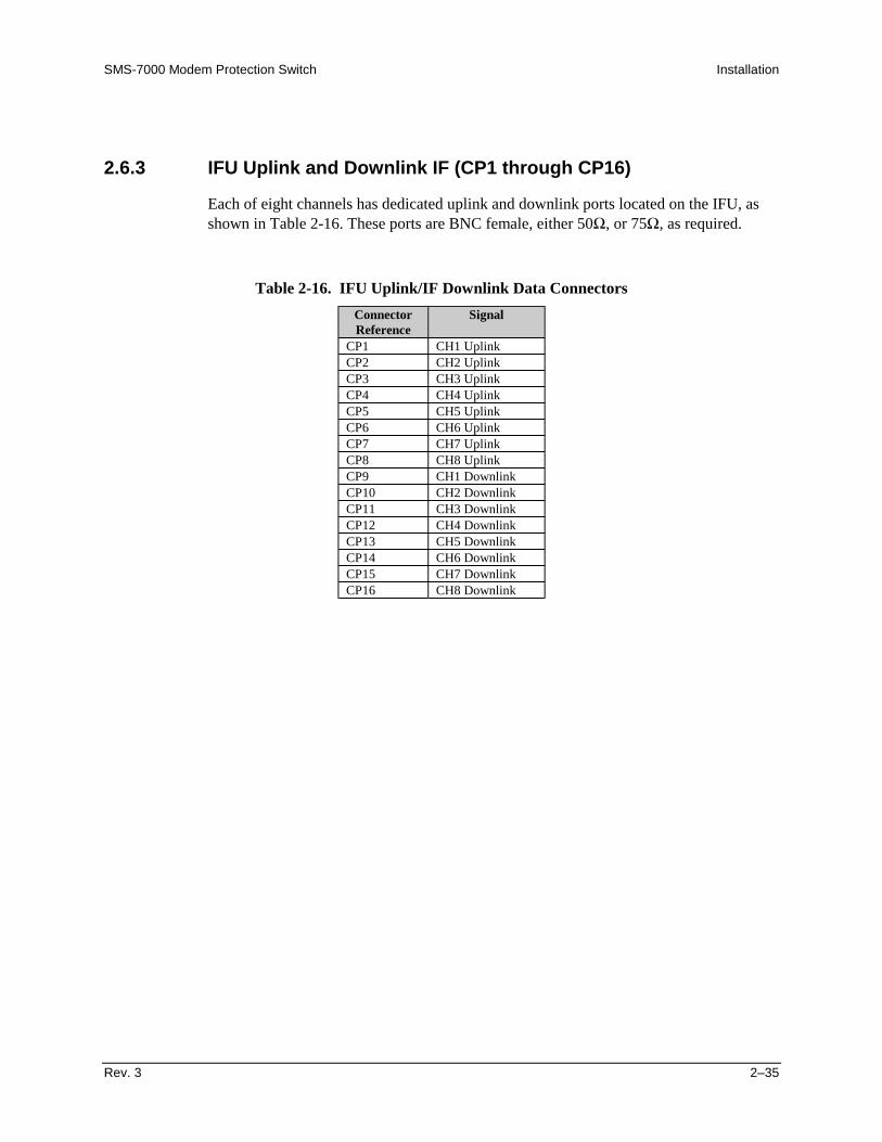
SMS-7000 Modem Protection Switch Installation
Rev. 3 2–35
2.6.3 IFU Uplink and Downlink IF (CP1 through CP16)
Each of eight channels has dedicated uplink and downlink ports located on the IFU, asshown in Table 2-16. These ports are BNC female, either 50Ω, or 75Ω, as required.
Table 2-16. IFU Uplink/IF Downlink Data Connectors
ConnectorReference
Signal
CP1 CH1 UplinkCP2 CH2 UplinkCP3 CH3 UplinkCP4 CH4 UplinkCP5 CH5 UplinkCP6 CH6 UplinkCP7 CH7 UplinkCP8 CH8 UplinkCP9 CH1 DownlinkCP10 CH2 DownlinkCP11 CH3 DownlinkCP12 CH4 DownlinkCP13 CH5 DownlinkCP14 CH6 DownlinkCP15 CH7 DownlinkCP16 CH8 Downlink

Installation SMS-7000 Modem Protection Switch
2–36 Rev. 3
This page is intentionally left blank.

Rev. 3 3–1
3Chapter 3. OPERATION
This chapter defines the controls and procedures for configuration and operation of theprotection switch.
Note: Familiarization with the front panel controls (Figure 3-1) and/or the related remotecommands described in Appendix A is recommended.
3.1 Configuration
The configuration of the protection switch may be performed from the front panel, orfrom a terminal or personal computer connected to the protection switch remote port(J1).
Each front panel menu screen has corresponding remote commands. The front paneldisplay menus are designed to guide the operator through the configuration process.
Note: Refer to the menu tables presented in this chapter for specific configurationinformation.
Figure 3-1. SMS-7000 Front Panel View

Operation SMS-7000 Modem Protection Switch
3–2 Rev. 3
3.1.1 Backup Modems
The configuration of the backup modems (1 or 2) is usually performed first. Each backupis defined to switch either independently or dependently, as a function of RX or TXfaults in the assigned prime modems.
A set of prime modems can be assigned using the backup configuration menu (refer toFigure 3-3). Individual prime MOD and DEMOD priority and delay options are availablewhen the backup modem is intended to backup the MOD and DEMOD independently.The independent backup will only backup the modems that are selected in the set underthe ‘Backup #n Prime Modems’ menu.
3.1.2 Prime Modems
When progressing into the prime modem (1 through 8) configuration menus, twopossible menu sets are available: independent or dependent.
• If assigned to a backup designated as independent, the modem configurationmenu set provides for setting the TX and RX parameters independently.
• If assigned to a dependent backup, no distinction is made between RX and TX inthe menu.
3.2 Front Panel
The protection switch front panel (Figure 3-1) provides a local interface to configure,operate, and monitor the switch. For remote control operation information, refer toAppendix A.
The front panel features:
• 48-character, 2-line, back-lit Liquid Crystal Display (LCD).
• 6-key, user friendly keypad that provides a wide variety of functions.
• 8 Light-Emitting Diodes (LEDs) on the front panel to provide overall status at aglance.

SMS-7000 Modem Protection Switch Operation
Rev. 3 3–3
3.2.1 LED Indicators
The eight LEDs on the front panel indicate the following (see Table 3-1):
Table 3-1. LED Indicators
Name LED DescriptionStatus
Power On Green Indicates that power is applied to the switch.Auto Green Indicates the switch is automatically assigning backup modems.Manual Green Indicates the backup modems are being assigned as directed by the user
from the manual menu.Switch Fault
System Red Indicates a communications failure or a configuration anomaly betweenthe switch and the attached modems. Specifics are displayed in theFault/Alarm menu. For example, mixing modems (without payingattention to Table 1-1) in a rack will cause this fault, due to differences inthe remote communications commands.
Equipment Red Indicates a communications failure between the switch modules or adetected fault within the switch hardware. Specifics are displayed in theFault/Alarm menu. For example, a power supply not plugged in willindicate this fault.
Stored Yellow Indicates that a fault occurrence has been logged and stored. Specifics aredisplayed in the Stored Fault/Alarms menu.The fault may or may not be active.
Transmit Yellow Indicates a faulted prime modulator which has not been backed up. Theidentity of the faulted modem(s) is displayed in the switch Fault/Alarmmenu. Specifics are displayed in the Fault/Alarm menu of the individualmodems. This fault clears when the faulted prime is backed up or whenthe fault is removed.
Receive Yellow Indicates a faulted prime demodulator which has not been backed up. Theidentity of the faulted modem(s) is displayed in the switch Fault/Alarmmenu. Specifics are displayed in the Fault/Alarm menu of the individualmodems. This fault clears when the faulted prime is backed up, or whenthe fault is removed.
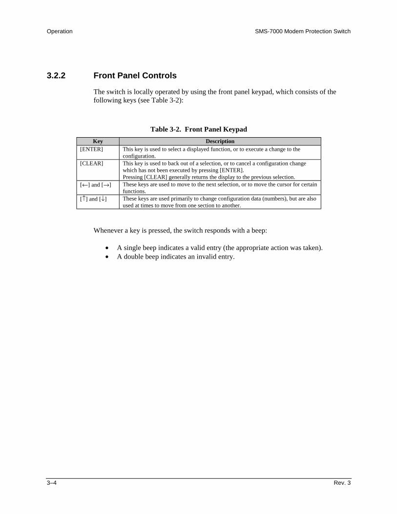
Operation SMS-7000 Modem Protection Switch
3–4 Rev. 3
3.2.2 Front Panel Controls
The switch is locally operated by using the front panel keypad, which consists of thefollowing keys (see Table 3-2):
Table 3-2. Front Panel Keypad
Key Description[ENTER] This key is used to select a displayed function, or to execute a change to the
configuration.[CLEAR] This key is used to back out of a selection, or to cancel a configuration change
which has not been executed by pressing [ENTER].Pressing [CLEAR] generally returns the display to the previous selection.
[←] and [→] These keys are used to move to the next selection, or to move the cursor for certainfunctions.
[↑] and [↓] These keys are used primarily to change configuration data (numbers), but are alsoused at times to move from one section to another.
Whenever a key is pressed, the switch responds with a beep:
• A single beep indicates a valid entry (the appropriate action was taken).• A double beep indicates an invalid entry.

SMS-7000 Modem Protection Switch Operation
Rev. 3 3–5
3.3 Menu System
Refer to Figure 3-2 through Figure 3-12 to access and execute all functions. Use the mainmenu in Figure 3-2 as a quick reference for accessing the protection switch functions.Refer to Section 3.2 for further configuration details.
When the protection switch power is turned ON, the base level of the menu systemdisplays the sign-on message:
• Line 1 of the sign-on message is the protection switch model number and type.• Line 2 is the version number of the firmware.
The main level of the menu system is Function Select. To access this level from thesign-on message, press the [←] or [→] keys. From the Function Select menu, select oneof the functional categories:
• Configuration• System Status• Faults/Alarms• Stored Faults/Alarms• Utility
Press [←] or [→] to move from one selection to another. When line 2 displays thedesired function, select that level by pressing [ENTER]. After entering the appropriatefunctional level, press [←] or [→] to move to the desired function.
To view or change the configuration of the protection switch, enter the Configurationlevel from the Function Select menu. While in the Configuration menu, press [←] or [→]to scroll through the Configuration menu selection.
Press [ENTER] to select the desired Configuration menu option. To view the options forthe selected configuration parameters, press [←] or [→]. To change a configurationparameter, press [ENTER] to begin the change process.
Press [↑] or [↓] to change the parameters. After the correct parameters are displayed,press [ENTER] to execute the change. This action initiates the necessary programmingby the protection switch. To undo a parameter change prior to execution, press[CLEAR].
Notes:1. Figure 3-2 through Figure 3-12 show the front panel menu window selections.2. Menus or commands that are specific to certain protection switch configurations
are only accessible after selecting the appropriate protection switchconfiguration. This prevents incompatible parameters from accidentally beingselected.

Operation SMS-7000 Modem Protection Switch
3–6 Rev. 3
This page is intentionally left blank.
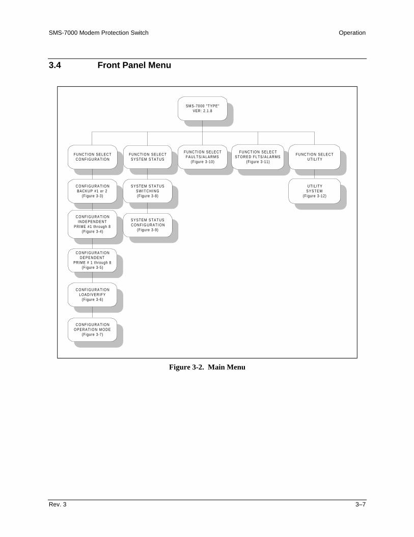
SMS-7000 Modem Protection Switch Operation
Rev. 3 3–7
3.4 Front Panel Menu
SMS-7000 "TYPE"VER: 2.1.8
FUNCTION SELECTC O N F I G U R A T I O N
FUNCTION SELECTSYSTEM STATUS
FUNCTION SELECTFAULTS/ALARMS
(Figure 3-10)
C O N F I G U R A T I O NBACKUP #1 or 2
(Figure 3-3)
C O N F I G U R A T I O NI N D E P E N D E N T
PRIME #1 through 8(Figure 3-4)
C O N F I G U R A T I O ND E P E N D E N T
PRIME # 1 through 8(Figure 3-5)
C O N F I G U R A T I O NLOAD/VERIFY
(Figure 3-6)
SYSTEM STATUSS W I T C H I N G(Figure 3-8)
SYSTEM STATUSC O N F I G U R A T I O N
(Figure 3-9)
FUNCTION SELECTSTORED FLTS /ALARMS
(Figure 3-11)
FUNCTION SELECTUTIL ITY
UTIL ITYS Y S T E M
(Figure 3-12)
C O N F I G U R A T I O NO P E R A T I O N M O D E
(Figure 3-7)
Figure 3-2. Main Menu
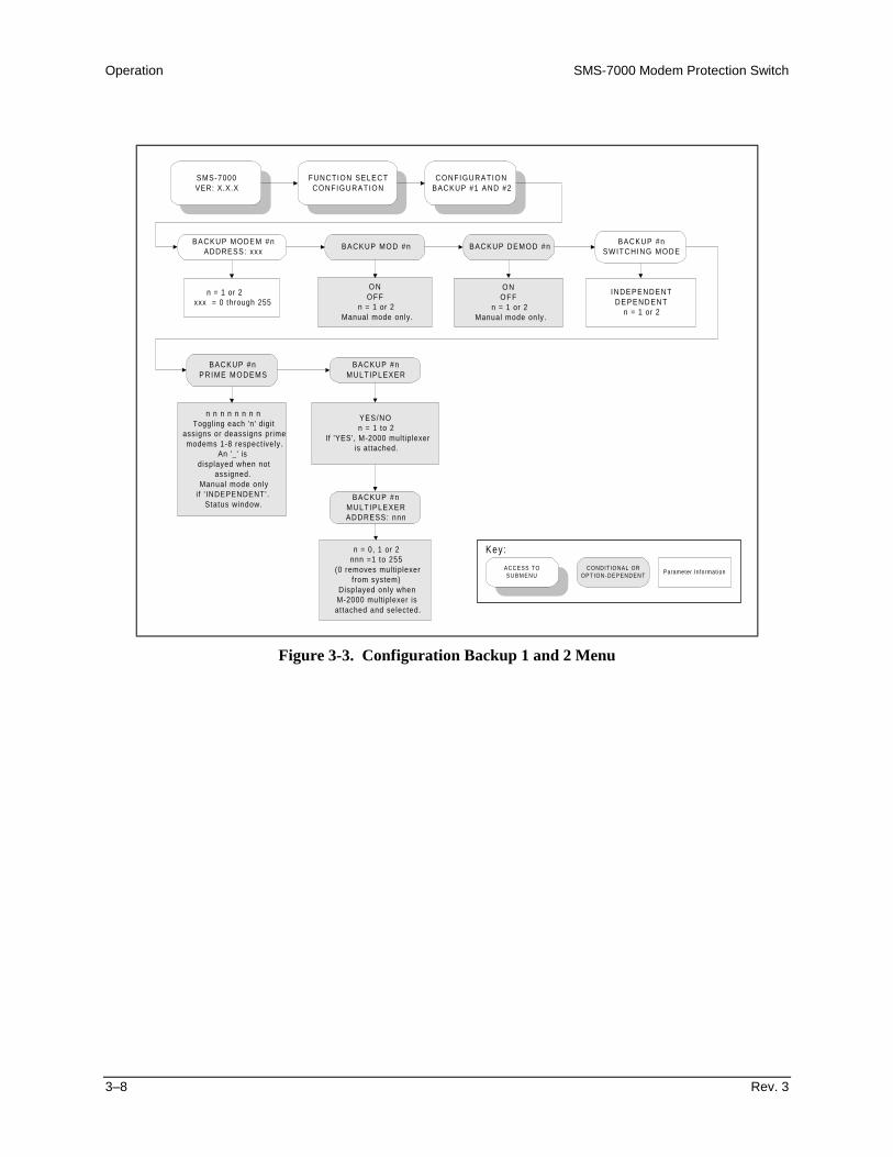
Operation SMS-7000 Modem Protection Switch
3–8 Rev. 3
SMS-7000VER: X.X.X
FUNCTION SELECTCONFIGURATION
CONFIGURATIONBACKUP #1 AND #2
BACKUP MODEM #nADDRESS: xxx
BACKUP MOD #n BACKUP DEMOD #n
BACKUP #nPRIME MODEMS
BACKUP #nMULTIPLEXER
BACKUP #nMULTIPLEXERADDRESS: nnn
n = 1 or 2 xxx = 0 through 255
O NOFF
n = 1 or 2Manual mode only.
O NOFF
n = 1 or 2Manual mode only.
n n n n n n n nToggling each 'n' digit
assigns or deassigns primemodems 1-8 respectively.
An '_' isdisplayed when not
assigned.Manual mode only
i f ' INDEPENDENT'.Status window.
YES/NOn = 1 to 2
If 'YES', M-2000 multiplexeris attached.
n = 0, 1 or 2nnn =1 to 255
(0 removes multiplexerfrom system)
Displayed only whenM-2000 multiplexer isattached and selected.
ACCESS TOSUBMENU
CONDITIONAL OROPTION-DEPENDENT
Parameter Information
Key:
BACKUP #nSWITCHING MODE
INDEPENDENTDEPENDENT
n = 1 or 2
Figure 3-3. Configuration Backup 1 and 2 Menu
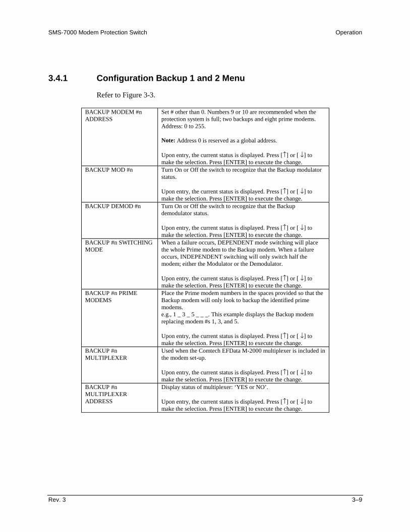
SMS-7000 Modem Protection Switch Operation
Rev. 3 3–9
3.4.1 Configuration Backup 1 and 2 Menu
Refer to Figure 3-3.
BACKUP MODEM #nADDRESS
Set # other than 0. Numbers 9 or 10 are recommended when theprotection system is full; two backups and eight prime modems.Address: 0 to 255.
Note: Address 0 is reserved as a global address.
Upon entry, the current status is displayed. Press [↑] or [ ↓] tomake the selection. Press [ENTER] to execute the change.
BACKUP MOD #n Turn On or Off the switch to recognize that the Backup modulatorstatus.
Upon entry, the current status is displayed. Press [↑] or [ ↓] tomake the selection. Press [ENTER] to execute the change.
BACKUP DEMOD #n Turn On or Off the switch to recognize that the Backupdemodulator status.
Upon entry, the current status is displayed. Press [↑] or [ ↓] tomake the selection. Press [ENTER] to execute the change.
BACKUP #n SWITCHINGMODE
When a failure occurs, DEPENDENT mode switching will placethe whole Prime modem to the Backup modem. When a failureoccurs, INDEPENDENT switching will only switch half themodem; either the Modulator or the Demodulator.
Upon entry, the current status is displayed. Press [↑] or [ ↓] tomake the selection. Press [ENTER] to execute the change.
BACKUP #n PRIMEMODEMS
Place the Prime modem numbers in the spaces provided so that theBackup modem will only look to backup the identified primemodems.e.g., 1 _ 3 _ 5 _ _ _. This example displays the Backup modemreplacing modem #s 1, 3, and 5.
Upon entry, the current status is displayed. Press [↑] or [ ↓] tomake the selection. Press [ENTER] to execute the change.
BACKUP #nMULTIPLEXER
Used when the Comtech EFData M-2000 multiplexer is included inthe modem set-up.
Upon entry, the current status is displayed. Press [↑] or [ ↓] tomake the selection. Press [ENTER] to execute the change.
BACKUP #nMULTIPLEXERADDRESS
Display status of multiplexer: ‘YES or NO’.
Upon entry, the current status is displayed. Press [↑] or [ ↓] tomake the selection. Press [ENTER] to execute the change.

Operation SMS-7000 Modem Protection Switch
3–10 Rev. 3
SMS-7000VER: X.X.X
FUNCTION SELECTCONFIGURATION
CONFIGURATIONINDEPENDENT
PRIME #n
PRIME MODEM #nADDRESS: xxx
PRIME MOD #nPRIME MOD #n
PRIORITYPRIME MOD #n
DELAY
PRIME DEMOD #n
O NO F F
n = 1 through 8Manual mode only.
H IGHMEDIUM
L O Wn = 1 through 8
O NO F F
n = 1 through 8Manual mode only.
n = 1 through 8xxx = 0 through 255
0 removes pr ime modemfrom system.
N O N EMANUAL
n = 1 through 8
HIGHMEDIUM
L O Wn = 1 through 8
PRIME DEMOD #nDELAY
N O N EA U T O
MANUALn = 1 through 8
BREAKOUT #nCONFIGURATION
PRIME #nMULTIPLEXER
PRIME #nMULTIPLEXERADDRESS: xxx
YESN O
n = 1 through 8If 'YES',
the fol lowing selectionwil l be displayed.
n = 1 through 8xxx = 0 to 255
Displayed only i f'YES' is selected in
the previous window.
PRIME DEMOD #nPRIORITY
BREAKOUT #nEXTERNAL CLOCK
BREAKOUT #nINSERT DATA INPUT
BREAKOUT #nD & I
BALANCEDUNBALANCED
L O O PN O R M A L
Used for tying DDO toIDI for using insertclock as the buffer
clock source
BALANCEDUNBALANCED
A C C E S S T OS U B M E N U
C O N D I T I O N A L O ROPTION-
D E P E N D E N T
ParameterInformat ion
Key:
n = 1 through 8
Figure 3-4. Configuration Independent Prime 1 through 8 Menu

SMS-7000 Modem Protection Switch Operation
Rev. 3 3–11
3.4.2 Configuration Independent Prime 1 through 8 Menu
Refer to Figure 3-4.
PRIME MODEM #nADDRESS
Set # other than 0. Address 0 is a global address which is used tocommunicate with all modems even though the address is set tosomething else.
Address: 0 to 255
Upon entry, the current status is displayed. Press [↑] or [ ↓] to makethe selection. Press [ENTER] to execute the change.
PRIME MOD #n Must be On for the switch to recognize it as active.
Upon entry, the current status is displayed. Press [↑] or [ ↓] to makethe selection. Press [ENTER] to execute the change.
PRIME MOD #nPRIORITY
Options: LOW, MEDIUM, and HIGH.
Upon entry, the current status is displayed. Press [↑] or [ ↓] to makethe selection. Press [ENTER] to execute the change.
PRIME MOD #n DELAY NONEMANUAL = 0.5 to 127.0 SEC.
Upon entry, the current status is displayed. Press [↑] or [ ↓] to makethe selection. Press [ENTER] to execute the change.
PRIME DEMOD #n Must be On for the switch to recognize it as active.
Upon entry, the current status is displayed. Press [↑] or [ ↓] to makethe selection. Press [ENTER] to execute the change.
PRIME DEMOD #nPRIORITY
Options: LOW, MEDIUM, and HIGH.
Upon entry, the current status is displayed, Press [↑] or [ ↓] to makethe selection. Press [ENTER to execute the change.
PRIME DEMOD #nDELAY
NONEAUTOMANUAL = 0.5 to 127.0 SEC.
Upon entry, the current status is displayed. Press [↑] or [ ↓] to makethe selection. Press [ENTER] to execute the change.
PRIME #nMULTIPLEXER
Displayed if multiplexer is; ‘YES or NO.’
Upon entry, the current status is displayed. Press [↑] or [ ↓] to makethe selection. Press [ENTER] to execute the change.
PRIME DEMOD #nMULTIPLEXERADDRESS
(Menu applies, only ifmultiplexer is attached.)
Set # other than 0. Address 0 removes the multiplexer from thesystem.
Address: 0 to 255
Upon entry, the current status is displayed. Press [↑] or [ ↓] to makethe selection. Press [ENTER] to execute the change.

Operation SMS-7000 Modem Protection Switch
3–12 Rev. 3
BREAKOUT #nCONFIGURATION
Press [ENTER] to access submenus.
D & I Use the BNC connectors for Unbalanced.Use the DB15 connector for Balanced.
EXTERNAL CLOCK Use the BNC connectors for Unbalanced.Use the DB15 connector for Balanced
INSERT DATA INPUT Options: NORMAL or LOOPLoop will connect DDO to IDI for D & I operation. This allowsoperator to select “insert clock” as the buffer clock source.

SMS-7000 Modem Protection Switch Operation
Rev. 3 3–13
This page is intentionally left blank.
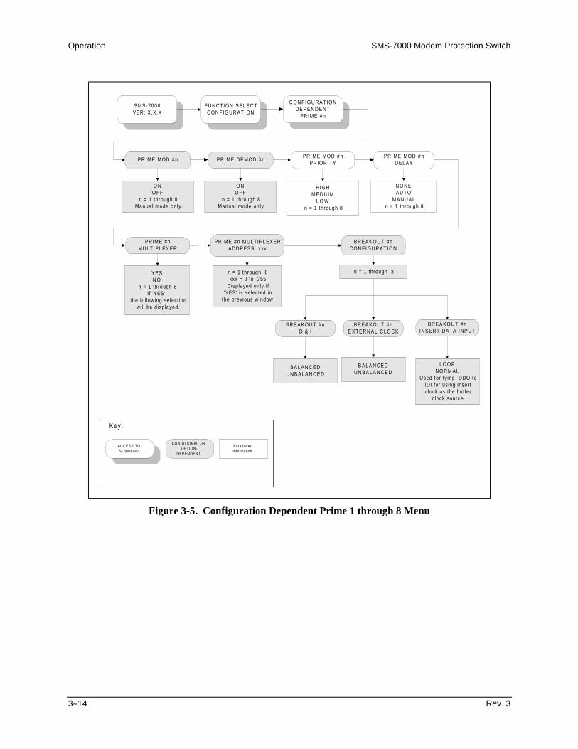
Operation SMS-7000 Modem Protection Switch
3–14 Rev. 3
SMS-7000VER: X.X.X
FUNCTION SELECTC O N F I G U R A T I O N
C O N F I G U R A T I O ND E P E N D E N T
PRIME #n
PRIME MOD #n PRIME DEMOD #nPRIME MOD #n
PRIORITYPRIME MOD #n
D E L A Y
PRIME #nMULT IPLEXER
O NO F F
n = 1 through 8Manual mode only .
H IGHM E D I U M
L O Wn = 1 through 8
YESN O
n = 1 through 8If 'YES',
the fol lowing select ionwi l l be displayed.
O NO F F
n = 1 through 8Manual mode only .
N O N EA U T O
M A N U A Ln = 1 through 8
n = 1 through 8xxx = 0 to 255
Displayed only i f'YES' is selected in
the previous window.
BREAKOUT #nC O N F I G U R A T I O N
PRIME #n MULTIPLEXERADDRESS: xxx
BREAKOUT #nE X T E R N A L C L O C K
BREAKOUT #nINSERT DATA INPUT
BREAKOUT #nD & I
B A L A N C E DU N B A L A N C E D
L O O PN O R M A L
Used for ty ing DDO toIDI for using insertc lock as the buffer
c lock source
B A L A N C E DU N B A L A N C E D
ACCESS TOSUBMENU
CONDITIONAL OROPTION-
DEPENDENT
ParameterInformation
Key:
n = 1 through 8
Figure 3-5. Configuration Dependent Prime 1 through 8 Menu

SMS-7000 Modem Protection Switch Operation
Rev. 3 3–15
3.4.3 Configuration Dependent Prime 1 through 8 Menu
Refer to Figure 3-5.
PRIME MODEM #nADDRESS
Set # other than 0. Address 0 is a global address.
Upon entry, the current status is displayed. Press [↑] or [ ↓] to makethe selection. Press [ENTER] to execute the change.
PRIME MOD #n Must be On for the switch to recognize as active.
Upon entry, the current status is displayed. Press [↑] or [ ↓] to makethe selection. Press [ENTER] to execute the change.
PRIME DEMOD #n Must be On for the switch to recognize as active.
Upon entry, the current status is displayed. Press [↑] or [ ↓] to makethe selection. Press [ENTER] to execute the change.
PRIME MODEM #nPRIORITY
Options: LOW, MEDIUM, and HIGH.
Upon entry, the current status is displayed. Press [↑] or [ ↓] to makethe selection. Press [ENTER] to execute the change.
PRIME MODEM #nDELAY
AUTO = 2 times sweep periodMANUAL = 0.5 to 127.0 SEC.To switch properly in DEPENDENT mode, the Prime modem demodsmust have input from a source modem other than their own. Otherwise,when the delay is set to NONE, the switch will oscillate between primeand backup modems. This occurs because the output of the modulatorhas been interrupted while the whole modem attempts to switch.
Upon entry, the current status is displayed. Press [↑] or [ ↓] to makethe selection. Press [ENTER] to execute the change.
PRIME #n MULTIPLEXER Displayed if multiplexer is; ‘YES or NO.’
Upon entry, the current status is displayed. Press [↑] or [ ↓] to makethe selection. Press [ENTER] to execute the change.
PRIME DEMOD #nMULTIPLEXERADDRESS
(Menu applies, only ifmultiplexer is attached.)
Set # other than 0. Address 0 removes the multiplexer from the system.
Address: 0 to 255
Upon entry, the current status is displayed. Press [↑] or [ ↓] to makethe selection. Press [ENTER] to execute the change.
BREAKOUT #nCONFIGURATION
Press [ENTER] to access submenus.
D & I Use the BNC connectors for Unbalanced.Use the DB15 connector for Balanced.
EXTERNAL CLOCK Use the BNC connectors for Unbalanced.Use the DB15 connector for Balanced.
INSERT DATA INPUT Options: NORMAL/LOOPSelect LOOP if insert clock is selected as receive buffer clock source atthe modem. This connects DDO to IDI. (Drop Data Out to Insert DataIn).
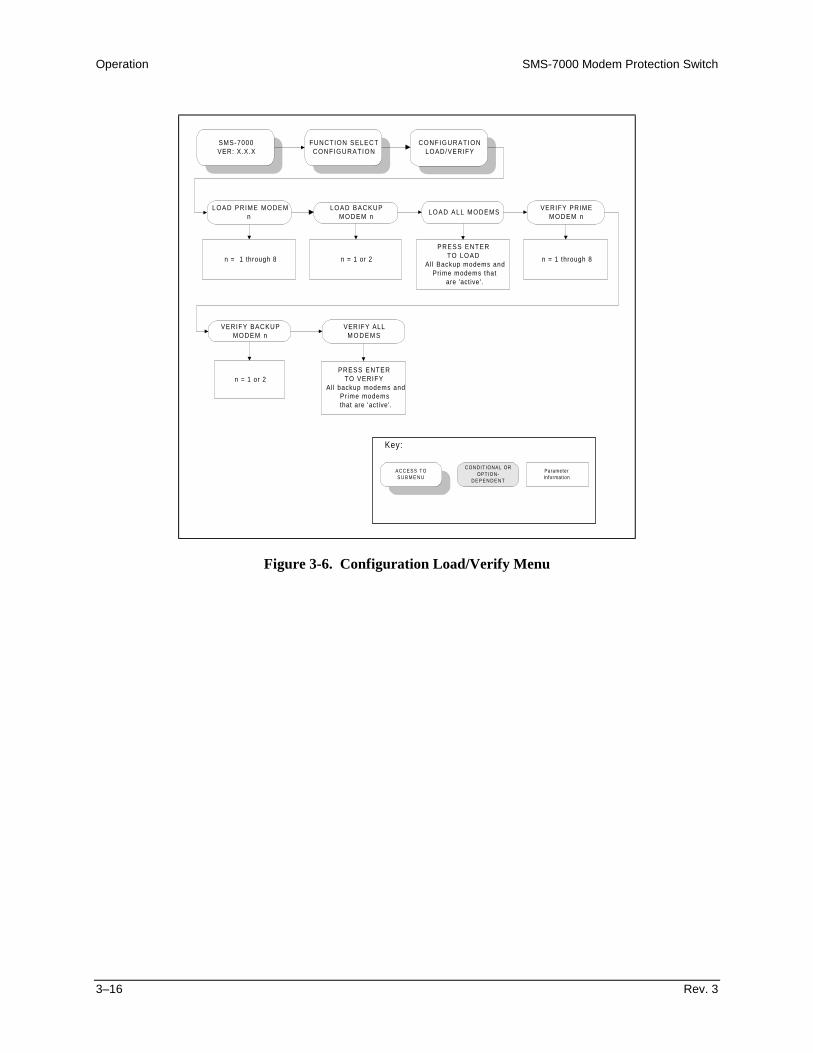
Operation SMS-7000 Modem Protection Switch
3–16 Rev. 3
SMS-7000VER: X.X.X
FUNCTION SELECTCONFIGURATION
CONFIGURATIONLOAD/VERIFY
LOAD PRIME MODEMn
LOAD BACKUPMODEM n
LOAD ALL MODEMSVERIFY PRIME
MODEM n
VERIFY BACKUPMODEM n
n = 1 or 2
n = 1 or 2
n = 1 through 8 n = 1 through 8
VERIFY ALLM O D E M S
A C C E S S T OS U B M E N U
CONDIT IONAL OROPTION-
D E P E N D E N T
ParameterInformation
Key:
PRESS ENTERTO LOAD
All Backup modems andPrime modems that
are 'active'.
PRESS ENTERTO VERIFY
Al l backup modems andPr ime modemsthat are 'active'.
Figure 3-6. Configuration Load/Verify Menu
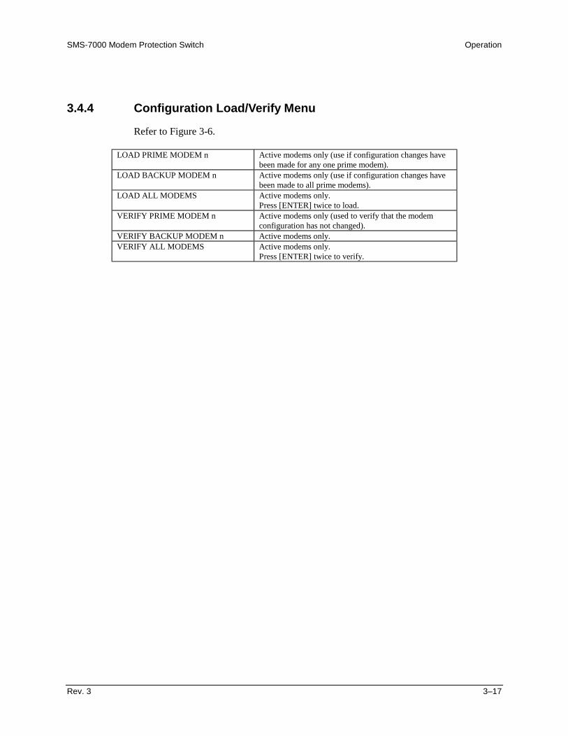
SMS-7000 Modem Protection Switch Operation
Rev. 3 3–17
3.4.4 Configuration Load/Verify Menu
Refer to Figure 3-6.
LOAD PRIME MODEM n Active modems only (use if configuration changes havebeen made for any one prime modem).
LOAD BACKUP MODEM n Active modems only (use if configuration changes havebeen made to all prime modems).
LOAD ALL MODEMS Active modems only.Press [ENTER] twice to load.
VERIFY PRIME MODEM n Active modems only (used to verify that the modemconfiguration has not changed).
VERIFY BACKUP MODEM n Active modems only.VERIFY ALL MODEMS Active modems only.
Press [ENTER] twice to verify.

Operation SMS-7000 Modem Protection Switch
3–18 Rev. 3
BACKUP #1 MODBACKUP PRIME
MODEM: n
ACCESS TOSUBMENU
CONDITIONAL OROPTION-
DEPENDENT
ParameterInformation
Key:
MANUAL - Enables submenus for d i rect contro l ofthe protect ion swi tch. The submenu displayeddepends on the swi t iching mode of the currentbackup modem ( Independent or Dependent) .
Backups # 1 or 2Independent
n = 0, or 1 to 8Enter 1 to 8 for onl ine,
0 for off- l ine.
BACKUP #1MODEM, BACKUPPRIME MODEM: n
n = 0, or 1 to 8Enter 1 to 8 for onl ine,
0 for off- l ine.
BACKUP #1 DEMODBACKUP PRIME
MODEM: n
n = 0, or 1 to 8Enter 1 to 8 for onl ine,
0 for off- l ine.
Backups # 1 or 2Dependent
SMS-7000VER: X.X.X
FUNCTION SELECTC O N F I G U R A T I O N
C O N F I G U R A T I O NO P E R A T I O N M O D E
O P E R A T I O N M O D E
A U T OM A N U A L
A U T O M A N U A L
AUTO - Al lows thebackup modem to rep lace
the pr ime modemautomatical ly.
Figure 3-7. Configuration Operation Mode Menu
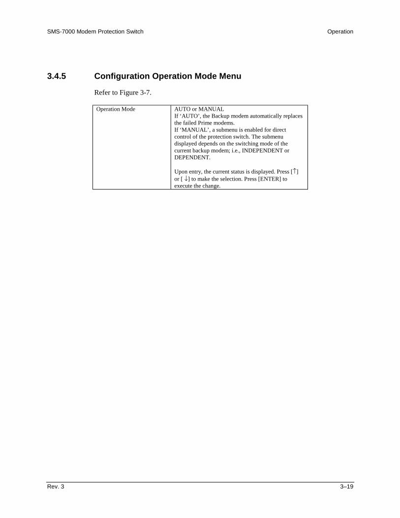
SMS-7000 Modem Protection Switch Operation
Rev. 3 3–19
3.4.5 Configuration Operation Mode Menu
Refer to Figure 3-7.
Operation Mode AUTO or MANUALIf ‘AUTO’, the Backup modem automatically replacesthe failed Prime modems.If ‘MANUAL’, a submenu is enabled for directcontrol of the protection switch. The submenudisplayed depends on the switching mode of thecurrent backup modem; i.e., INDEPENDENT orDEPENDENT.
Upon entry, the current status is displayed. Press [↑]or [ ↓] to make the selection. Press [ENTER] toexecute the change.

Operation SMS-7000 Modem Protection Switch
3–20 Rev. 3
SMS-7000VER: X.X.X
FUNCTION SELECTSYSTEM STATUS
SYSTEM STATUSSWITCHING
MOD mmmmmmmm Byxn BzxnDMD dddddddd Byxn Bzxn
A C C E S S T OS U B M E N U
C O N D I T I O N A L O RO P T I O N -
D E P E N D E N T
Paramete rIn format ion
Key:
M O D m m m m m m m mBy xxxxx n Bz xxxxx n
Status Window
DEMOD ddddddddBy xxxxx n Bz xxxxx n
Status WindowStatus window.
Figure 3-8. System Status Switching Menu
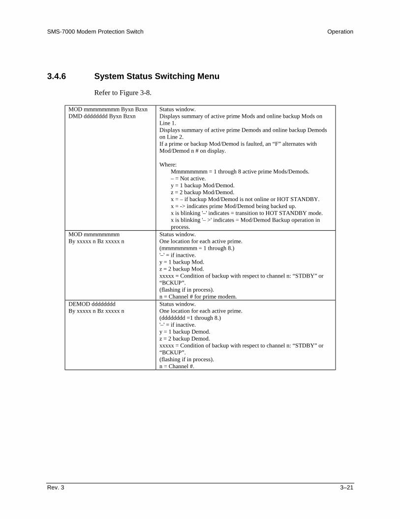
SMS-7000 Modem Protection Switch Operation
Rev. 3 3–21
3.4.6 System Status Switching Menu
Refer to Figure 3-8.
MOD mmmmmmmm Byxn BzxnDMD dddddddd Byxn Bzxn
Status window.Displays summary of active prime Mods and online backup Mods onLine 1.Displays summary of active prime Demods and online backup Demodson Line 2.If a prime or backup Mod/Demod is faulted, an “F” alternates withMod/Demod n # on display.
Where:Mmmmmmmm = 1 through 8 active prime Mods/Demods.– = Not active.y = 1 backup Mod/Demod.z = 2 backup Mod/Demod.x = – if backup Mod/Demod is not online or HOT STANDBY.x = -> indicates prime Mod/Demod being backed up.x is blinking '–' indicates = transition to HOT STANDBY mode.x is blinking '– >' indicates = Mod/Demod Backup operation inprocess.
MOD mmmmmmmmBy xxxxx n Bz xxxxx n
Status window.One location for each active prime.(mmmmmmmm = 1 through 8.)'–' = if inactive.y = 1 backup Mod.z = 2 backup Mod.xxxxx = Condition of backup with respect to channel n: “STDBY” or“BCKUP”.(flashing if in process).n = Channel # for prime modem.
DEMOD ddddddddBy xxxxx n Bz xxxxx n
Status window.One location for each active prime.(dddddddd =1 through 8.)'–' = if inactive.y = 1 backup Demod.z = 2 backup Demod.xxxxx = Condition of backup with respect to channel n: “STDBY” or“BCKUP”.(flashing if in process).n = Channel #.
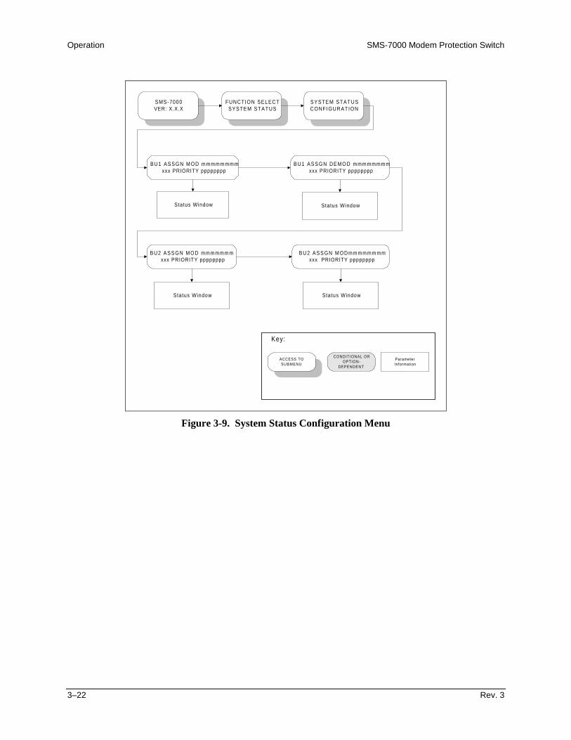
Operation SMS-7000 Modem Protection Switch
3–22 Rev. 3
SMS-7000VER: X.X.X
FUNCTION SELECTSYSTEM STATUS
SYSTEM STATUSCONFIGURATION
ACCESS TOSUBMENU
CONDITIONAL OROPTION-
DEPENDENT
ParameterInformation
Key:
B U 1 A S S G N M O D m m m m m m m mxxx PRIORITY pppppppp
Status Window
B U 1 A S S G N D E M O D m m m m m m m mxxx PRIORITY pppppppp
Status Window
B U 2 A S S G N M O D m m m m m m mxxx PRIORITY pppppppp
Status Window
B U 2 A S S G N M O D m m m m m m m mxxx PRIORITY pppppppp
Status Window
Figure 3-9. System Status Configuration Menu
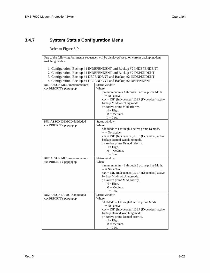
SMS-7000 Modem Protection Switch Operation
Rev. 3 3–23
3.4.7 System Status Configuration Menu
Refer to Figure 3-9.
One of the following four menus sequences will be displayed based on current backup modemswitching modes:
1. Configuration: Backup #1 INDEPENDENT and Backup #2 INDEPENDENT2. Configuration: Backup #1 INDEPENDENT and Backup #2 DEPENDENT3. Configuration: Backup #1 DEPENDENT and Backup #2 INDEPENDENT4. Configuration: Backup #1 DEPENDENT and Backup #2 DEPENDENT
BU1 ASSGN MOD mmmmmmmmxxx PRIORITY pppppppp
Status windowWhere:
mmmmmmmm = 1 through 8 active prime Mods.'–' = Not active.xxx = IND (Independent)/DEP (Dependent) activebackup Mod switching mode.p= Active prime Mod priority.
H = High.M = Medium.L = Low.
BU1 ASSGN DEMOD ddddddddxxx PRIORITY pppppppp
Status window.Where:
dddddddd = 1 through 8 active prime Demods.'–' = Not active.xxx = IND (Independent)/DEP (Dependent) activebackup Demod switching mode.p= Active prime Demod priority.
H = High.M = Medium.L = Low.
BU2 ASSGN MOD mmmmmmmmxxx PRIORITY pppppppp
Status window.Where:
mmmmmmmm = 1 through 8 active prime Mods.'–' = Not active.xxx = IND (Independent)/DEP (Dependent) activebackup Mod switching mode.p= Active prime Mod priority.
H = High.M = Medium.L = Low.
BU2 ASSGN DEMOD ddddddddxxx PRIORITY pppppppp
Status window.Where:
dddddddd = 1 through 8 active prime Mods.'–' = Not active.xxx = IND (Independent)/DEP (Dependent) activebackup Demod switching mode.p= Active prime Demod priority.
H = High.M = Medium.L = Low.

Operation SMS-7000 Modem Protection Switch
3–24 Rev. 3
SMS-7000VER: X.X.X
FUNCTION SELECTFAULTS/ALARMS
TX OPERATIONALFAULTS
A C C E S S T OS U B M E N U
C O N D I T I O N A L O RO P T I O N -
D E P E N D E N T
Paramete rIn format ion
Key:
BACKUP FAULT MOD#1 through 8
RX OPERATIONALFAULTS
BACKUP FAULT DEMOD#1 through 8
SYSTEM FAULTSBACKUP #n(n = 1 or 2)
BK-UP MODEM COMM FAILUREBMOD CONFIG VERIFY ERRORBDMD CONFIG VERIFY ERROR
NO ADDRESS FOR BK-UPNO MOD CONFIG LOADED
NO DEMOD CONFIG LOADEDNO PRIMES ASSIGNED
BK-UP MU COMM FAILURENO ADDRESS FOR BK-UP MU
(Displayed if multiplexer is attached)
SYSTEM FAULTSPRIME #n
(n = 1 through 8)
MODEM COMM FAILUREMOD CONFIG VERIFY ERRORDMD CONFIG VERIFY ERROR
NO ADDRESS FOR PRIMENO MOD CONFIG LOADED
NO DEMOD CONFIG LOADEDPRIME NOT ASSIGNED
PRIME MU COMM FAILURENO ADDRESS FOR PRIME MU
(Displayed if multiplexer is attached.)
EQUIPMENT FAULTS
DATA SWITCH MODULE #1DATA SWITCH MODULE #2DATA SWITCH MODULE #3DATA SWITCH MODULE #4DATA SWITCH MODULE #5DATA SWITCH MODULE #6DATA SWITCH MODULE #7DATA SWITCH MODULE #8
IF SWITCH MODULEPOWER SUPPLY 1 FAULTPOWER SUPPLY 2 FAULT
NVRAM/CLOCK FAULTM&C CONTROLLER FAULT
I2C BUS FAULT
Figure 3-10. Faults/Alarms Menu
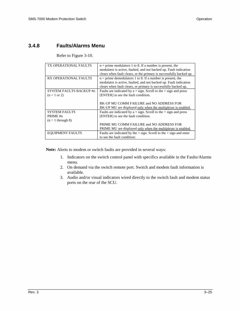
SMS-7000 Modem Protection Switch Operation
Rev. 3 3–25
3.4.8 Faults/Alarms Menu
Refer to Figure 3-10.
TX OPERATIONAL FAULTS n = prime modulators 1 to 8. If a number is present, themodulator is active, faulted, and not backed up. Fault indicationclears when fault clears, or the primary is successfully backed up.
RX OPERATIONAL FAULTS n = prime demodulators 1 to 8. If a number is present, themodulator is active, faulted, and not backed up. Fault indicationclears when fault clears, or primary is successfully backed up.
SYSTEM FAULTS BACKUP #n(n = 1 or 2)
Faults are indicated by a + sign. Scroll to the + sign and press[ENTER] to see the fault condition.
BK-UP MU COMM FAILURE and NO ADDRESS FORBK-UP MU are displayed only when the multiplexer is enabled.
SYSTEM FAULTSPRIME #n(n = 1 through 8)
Faults are indicated by a + sign. Scroll to the + sign and press[ENTER] to see the fault condition.
PRIME MU COMM FAILURE and NO ADDRESS FORPRIME MU are displayed only when the multiplexer is enabled.
EQUIPMENT FAULTS Faults are indicated by the + sign. Scroll to the + sign and enterto see the fault condition:
Note: Alerts to modem or switch faults are provided in several ways:
1. Indicators on the switch control panel with specifics available in the Faults/Alarmsmenu.
2. On demand via the switch remote port. Switch and modem fault information isavailable.
3. Audio and/or visual indicators wired directly to the switch fault and modem statusports on the rear of the SCU.

Operation SMS-7000 Modem Protection Switch
3–26 Rev. 3
SMS-7000VER: X.X.X
FUNCTION SELECTS T O R E D
FAULTS/ALARMS
TX OPERATIONALFAULTS x
HH:MM:SS MM/DD/YY
A C C E S S T OS U B M E N U
C O N D I T I O N A L O ROPTION-
D E P E N D E N T
ParameterInformat ion
Key:
BACKUP FAULT MOD #n(n = 1 through 8)
RX OPERATIONALFAULTS x
HH:MM:SS MM/DD/YY
B A C K U P F A U L T D E M O D # n(n = 1 through 8)
SYS FAULTSBACKUP #n x
HH:MM:SS MM/DD/YY
(n = 1 through 8)BK-UP MODEM COMM FAILUREBMOD CONFIG VERIFY ERRORBDMD CONFIG VERIFY ERROR
NO ADDRESS FOR BK-UPNO MOD CONFIG LOADED
N O D E M O D C O N F I G L O A D E DNO PRIMES ASSIGNED
BK-UP MU COMM FAILURENO ADDRESS FOR BK-UP MU
(Displayed i f mult ip lexer is at tached.)
SYS FAULTSPRIME #n
HH:MM:SS MM/DD/YY
(n = 1 through 8 )M O D E M C O M M F A I L U R E
MOD CONFIG VERIFY ERRORDMD CONFIG VERIFY ERROR
NO ADDRESS FOR PRIMENO MOD CONFIG LOADED
N O D E M O D C O N F I G L O A D E DPRIME NOT ASSIGNED
PRIME MU COMM FAILURENO ADDRESS FOR PRIME MU
(Displayed i f mult ip lexer is at tached.)
EQUIPMENT FAULTS(n = 1 through 8)
DATA SWITCH MODULE #nIF SWITCH MODULE
POWER SUPPLY 1 FAULTPOWER SUPPLY 2 FAULT
NVRAM/CLOCK FAULTM & C C O N T R O L L E R F A U L T
12C BUS FAULT
CLEAR ??S T O R E D F A U L T S
CLEAR ??YESN O
Figure 3-11. Stored Faults/Alarms Menu
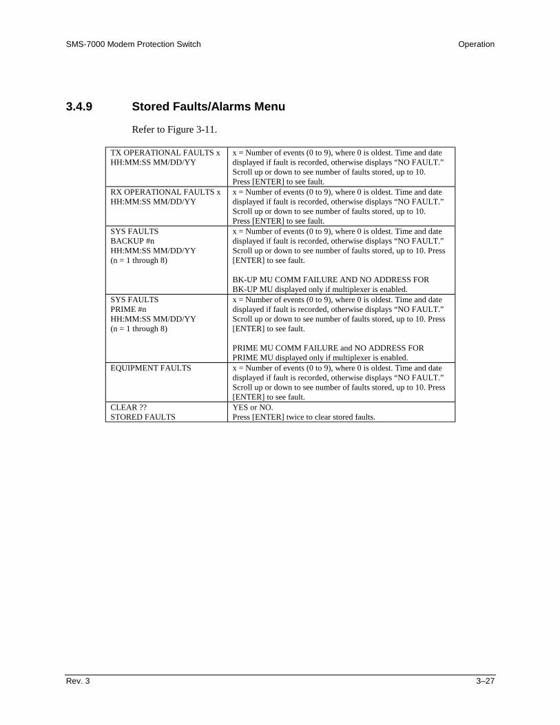
SMS-7000 Modem Protection Switch Operation
Rev. 3 3–27
3.4.9 Stored Faults/Alarms Menu
Refer to Figure 3-11.
TX OPERATIONAL FAULTS xHH:MM:SS MM/DD/YY
x = Number of events (0 to 9), where 0 is oldest. Time and datedisplayed if fault is recorded, otherwise displays “NO FAULT.”Scroll up or down to see number of faults stored, up to 10.Press [ENTER] to see fault.
RX OPERATIONAL FAULTS xHH:MM:SS MM/DD/YY
x = Number of events (0 to 9), where 0 is oldest. Time and datedisplayed if fault is recorded, otherwise displays “NO FAULT.”Scroll up or down to see number of faults stored, up to 10.Press [ENTER] to see fault.
SYS FAULTSBACKUP #nHH:MM:SS MM/DD/YY(n = 1 through 8)
x = Number of events (0 to 9), where 0 is oldest. Time and datedisplayed if fault is recorded, otherwise displays “NO FAULT.”Scroll up or down to see number of faults stored, up to 10. Press[ENTER] to see fault.
BK-UP MU COMM FAILURE AND NO ADDRESS FORBK-UP MU displayed only if multiplexer is enabled.
SYS FAULTSPRIME #nHH:MM:SS MM/DD/YY(n = 1 through 8)
x = Number of events (0 to 9), where 0 is oldest. Time and datedisplayed if fault is recorded, otherwise displays “NO FAULT.”Scroll up or down to see number of faults stored, up to 10. Press[ENTER] to see fault.
PRIME MU COMM FAILURE and NO ADDRESS FORPRIME MU displayed only if multiplexer is enabled.
EQUIPMENT FAULTS x = Number of events (0 to 9), where 0 is oldest. Time and datedisplayed if fault is recorded, otherwise displays “NO FAULT.”Scroll up or down to see number of faults stored, up to 10. Press[ENTER] to see fault.
CLEAR ??STORED FAULTS
YES or NO.Press [ENTER] twice to clear stored faults.
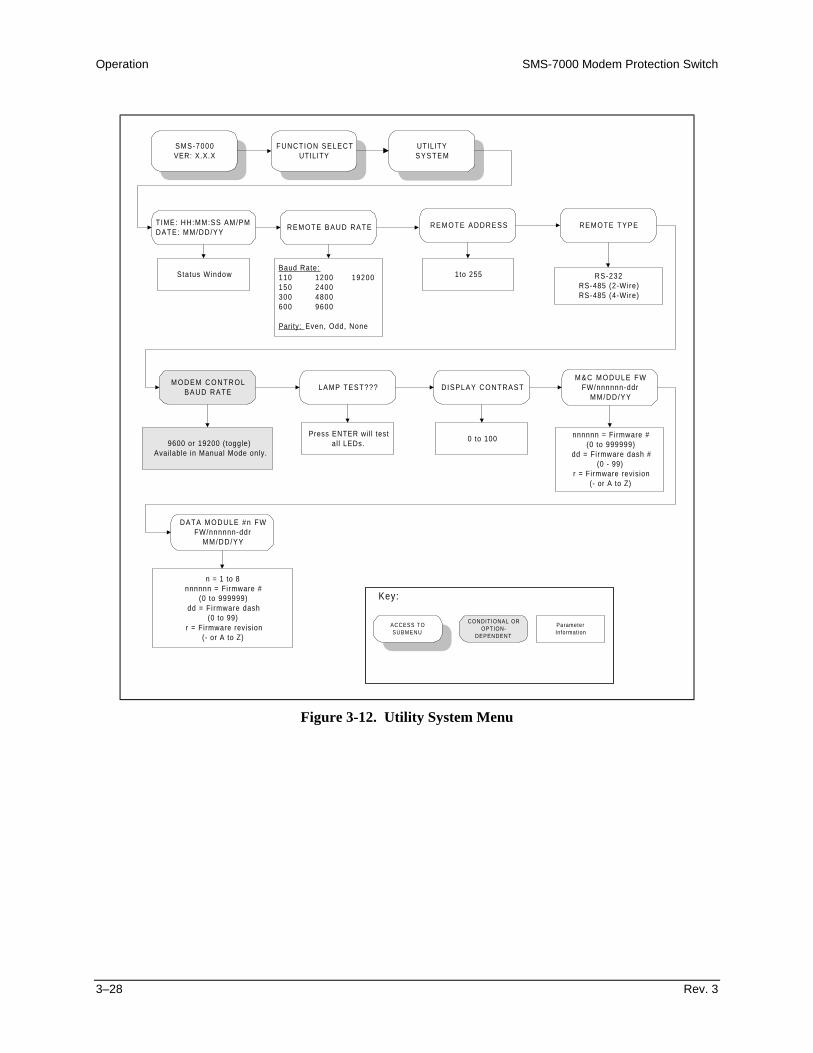
Operation SMS-7000 Modem Protection Switch
3–28 Rev. 3
SMS-7000VER: X.X.X
FUNCTION SELECTUTILITY
UTILITYS Y S T E M
TIME: HH:MM:SS AM/PMDATE: MM/DD/YY
ACCESS TOSUBMENU
CONDITIONAL OROPTION-
DEPENDENT
ParameterInformation
Key:
REMOTE BAUD RATE
Baud Rate:110 1200 19200150 2400300 4800600 9600
Parity: Even, Odd, None
R E M O T E A D D R E S S
1to 255
REMOTE TYPE
RS-232RS-485 (2-Wire)RS-485 (4-Wire)
M O D E M C O N T R O LBAUD RATE
9600 or 19200 (toggle)Available in Manual Mode only.
LAMP TEST??? DISPLAY CONTRAST
0 to 100
M & C M O D U L E F WFW/nnnnnn-ddr
MM/DD/YY
nnnnnn = Firmware #(0 to 999999)
dd = Firmware dash #(0 - 99)
r = Firmware revision(- or A to Z)
DATA MODULE #n FWFW/nnnnnn-ddr
MM/DD/YY
n = 1 to 8nnnnnn = Firmware #
(0 to 999999)dd = Firmware dash
(0 to 99)r = Firmware revision
(- or A to Z)
Status Window
Press ENTER wil l testal l LEDs.
Figure 3-12. Utility System Menu

SMS-7000 Modem Protection Switch Operation
Rev. 3 3–29
3.4.10 Utility System Menu
Refer to Figure 3-12.
TIME: HH:MM:SS AM/PMDATE: MMDDYY
Scroll left or right and press [↑] or [↓] to set, then press [ENTER].
REMOTE BAUD RATEnnnnn bit/s parity
This is the protocol set-up between the switch and an external terminal.The terminal may or may not be used to control the switch, or to makeconfiguration changes to the modems. Scroll left or right and press [↑] or[↓] to set, then press [ENTER].Rate Options: 19200, 9600, 4800, 2400, 1200, 600, 300, 150, 110.Parity: EVEN, ODD, or NONE.
REMOTE ADDRESSnnn
This is the address (nnn = 1 to 255) of the switch. Scroll left or right andpress [↑] or [↓] to set, then press [ENTER].
Note: Address 0 is reserved for global communications.REMOTE TYPEtype
Scroll left or right, then press [ENTER]. Options: EIA-485 (2- or4-wire), or EIA-232.
MODEM CONTROL BAUD RATEnnnnn bps
Scroll left or right, then press [ENTER]. Options: 9600 or 19.2 kbit/s.Controls the baud rate between the switch and the modems.
LAMP TEST ?? Press [ENTER] to test.DISPLAY CONTRASTLEVEL: nnn
Scroll left or right and press [↑] or [↓] to set, then press [ENTER].nnn = 1 to 100.Changes the darkness of the display characters.
M&C MODULE FIRMWAREFW/nnnnnn-ddr MM/DD/YY
Firmware # and date alternate on the display.
DATA MODULE #n FIRMWAREFW/nnnnnn-ddr MM/DD/YY
Firmware # and date alternate on the display.
Displays “NOT AVAILABLE” if not in system.

Operation SMS-7000 Modem Protection Switch
3–30 Rev. 3
3.5 Setup and Configuration
3.5.1 Utility Setup
Prior to configuration, it may be necessary to modify the following:
• Display Contrast — Adjust for optimum viewing in local ambient lightingconditions.
• Remote options — If a remote is to be used, appropriate remote options must beverified or defined from the Utility menus.
• Modem Control Baud Rate — Select the highest common baud rate for themodems attached to the switch.
3.5.2 Configuration
Once installed, the switch is ready for configuration to the specific applicationrequirements. The switch mode must be in ‘Manual’ to make most configurationchanges.
3.5.2.1 Backup
To configure the backup parameters, set the following:
• Address — Enter a unique 3-digit decimal address for remote communications.
• Mod/Demod, ON or OFF — Must be ON for consideration by the switchalgorithm.
• Switching Mode — Select Dependent or Independent RX/TX switching.
• Prime Modems — Enter prime modems to be supported by this backup.
Note: The system will not allow the same prime modem to be assigned tobackups with different switching modes. When pressing [ENTER], the systemwill beep twice and remove the prime from the backup list. For valid entry, theprime must first be removed from the other backup--or the other backup modemust be changed to agree.
SMS-7000 Modem Protection Switch Operation
Rev. 3 3–31
3.5.2.2 Prime
The mode of the backup to which the prime is assigned (Independent or Dependent)determines the menu provided for the prime by the system.
• Address — Enter a 3-digit decimal address for remote communications.
• Mod/Demod, ON or OFF — Must be ON for consideration by the switchalgorithm.
• Priority — This assignment, and the prime modem # (1 through 8), define theoverall priority used by the switch algorithm when a modem failure occurs. If theprime is backed up by an independent backup, RX and TX priorities are assignedseparately.
• Delay — Enter desired delay. If independent, enter delay for Mod and Demod.To switch properly in dependent mode, the prime modem demods must haveinput from a source modem other than their own. Otherwise, when the delay isset to NONE, the switch will oscillate between prime and backup modems. Thisoccurs because the output of the modulator has been interrupted while the wholemodem attempts to switch.
• Breakout Configuration — Select from available options, as applicable.
3.5.2.3 Load/Verify
Modem configuration must be loaded by the switch or the switch will not operateproperly.
• Load — If any modem configurations have been changed, they must be loadedprior to exiting the configuration menus. A load may be done for an individualmodem, or all modems.
• Verify — Retrieves the configuration from a modem, and compares it to theconfiguration stored in the switch. This ensures the switch uses the properconfiguration data when preparing a backup for service.
Note: Check the Fault menus for any reported problems with the loading orverifying.
Operation SMS-7000 Modem Protection Switch
3–32 Rev. 3
3.5.2.4 Operation Mode
Two modes of operation are available for the switch.
• Auto — Automatically allows the Backup modem to replace any prime modemwhen a MOD or DEMOD failure occurs.
• Manual — When Manual mode is selected, the system provides a dedicatedmenu through which the user may assign backup RX and TX functions to replacethe prime modems.
Enter 0 under the CONFIG/OPERATION MODE/MANUAL/MODEM BACKUPPRIME MODEM menu to place the backup service on the intended prime modem.
3.6 Faults
Alerts to modem or switch faults are provided in several ways:
• Indicators on the switch control panel with specific information available in theFault/Alarm menu.
• On demand via the switch remote port. Specifics for both switch and modemfaults are available.
• Audio and/or visual indicators wired directly to the Switch Fault and ModemStatus ports on the rear of the SCU.
Refer to Chapter 5 for troubleshooting switch faults and modem faults.
3.7 Revision Status
Refer to Table 3-3 for revision software history.
Table 3-3. Revision Status
Revision FW/4958-1 Description1.1.1 – Original Issue1.1.2 A User interface changes2.1.1 B Added M2000 Multiplexer and revision emulation functionality.2.1.2 C User interface changes.2.1.3 D User interface changes.2.1.4 E Corrected communication faults on modem, data, and IF module.2.1.5 F Corrected automatic mode problem.2.1.6 G Corrected backup of SLM8650 and SLM6650 for 6650-00,
6650-02, 8650-00, 8650-02, 3650-00, 3650-02 modem types.2.1.7 H Corrected online signal problem.2.1.8 J Allow switch to operate with SDM8000 modem.
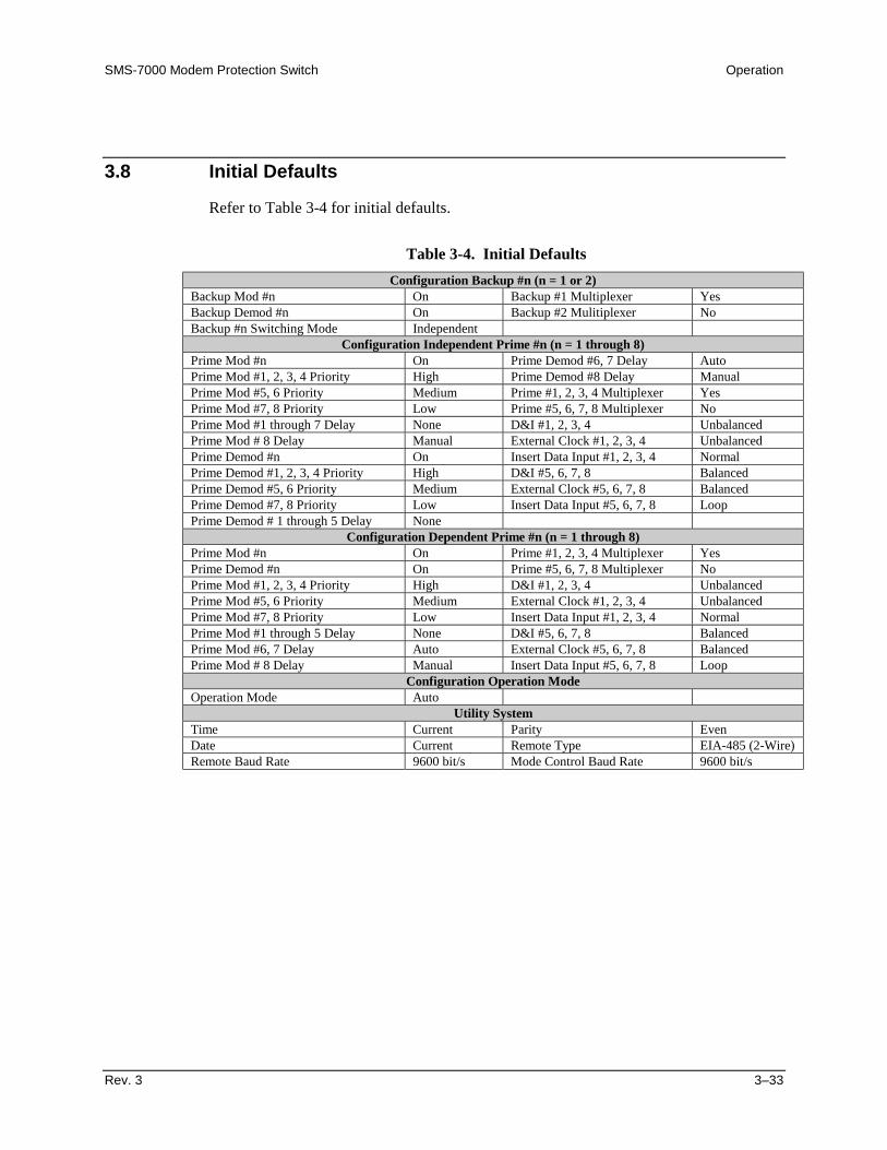
SMS-7000 Modem Protection Switch Operation
Rev. 3 3–33
3.8 Initial Defaults
Refer to Table 3-4 for initial defaults.
Table 3-4. Initial Defaults
Configuration Backup #n (n = 1 or 2)Backup Mod #n On Backup #1 Multiplexer YesBackup Demod #n On Backup #2 Mulitiplexer NoBackup #n Switching Mode Independent
Configuration Independent Prime #n (n = 1 through 8)Prime Mod #n On Prime Demod #6, 7 Delay AutoPrime Mod #1, 2, 3, 4 Priority High Prime Demod #8 Delay ManualPrime Mod #5, 6 Priority Medium Prime #1, 2, 3, 4 Multiplexer YesPrime Mod #7, 8 Priority Low Prime #5, 6, 7, 8 Multiplexer NoPrime Mod #1 through 7 Delay None D&I #1, 2, 3, 4 UnbalancedPrime Mod # 8 Delay Manual External Clock #1, 2, 3, 4 UnbalancedPrime Demod #n On Insert Data Input #1, 2, 3, 4 NormalPrime Demod #1, 2, 3, 4 Priority High D&I #5, 6, 7, 8 BalancedPrime Demod #5, 6 Priority Medium External Clock #5, 6, 7, 8 BalancedPrime Demod #7, 8 Priority Low Insert Data Input #5, 6, 7, 8 LoopPrime Demod # 1 through 5 Delay None
Configuration Dependent Prime #n (n = 1 through 8)Prime Mod #n On Prime #1, 2, 3, 4 Multiplexer YesPrime Demod #n On Prime #5, 6, 7, 8 Multiplexer NoPrime Mod #1, 2, 3, 4 Priority High D&I #1, 2, 3, 4 UnbalancedPrime Mod #5, 6 Priority Medium External Clock #1, 2, 3, 4 UnbalancedPrime Mod #7, 8 Priority Low Insert Data Input #1, 2, 3, 4 NormalPrime Mod #1 through 5 Delay None D&I #5, 6, 7, 8 BalancedPrime Mod #6, 7 Delay Auto External Clock #5, 6, 7, 8 BalancedPrime Mod # 8 Delay Manual Insert Data Input #5, 6, 7, 8 Loop
Configuration Operation ModeOperation Mode Auto
Utility SystemTime Current Parity EvenDate Current Remote Type EIA-485 (2-Wire)Remote Baud Rate 9600 bit/s Mode Control Baud Rate 9600 bit/s

Operation SMS-7000 Modem Protection Switch
3–34 Rev. 3
This page is intentionally left blank.
Rev. 3 4–1
4Chapter 4. THEORY OF OPERATION
This chapter provides the theory of operation for the switch and explains variousinterfaces and switching modes.
4.1 Interfaces
4.1.1 Configuration
The configuration interfaces (J1 and J2) are located on the rear panel of the SCU (referto Figure 4-1).
• User remote (J1) is the remote port for configuration and control of the switchand associated modems. From the SCU front panel utilities menu (refer toChapter 3), J1 is defined as EIA-232 or EIA-485 at 110 to 19200 baud rate.
• Modem remote (J2) is the port through which the switch controls and monitorsmodem configurations.
The J1 and J2 serial ports are electrically isolated but share the same address space. Theswitch buffers communicate between the two ports. This enables a remote user tocommunicate directly with the switch or modems attached to the switch, as though theports were directly connected.
If the switch is communicating with a modem at the time the remote user issues acommand, the switch responds with “BUSY.”
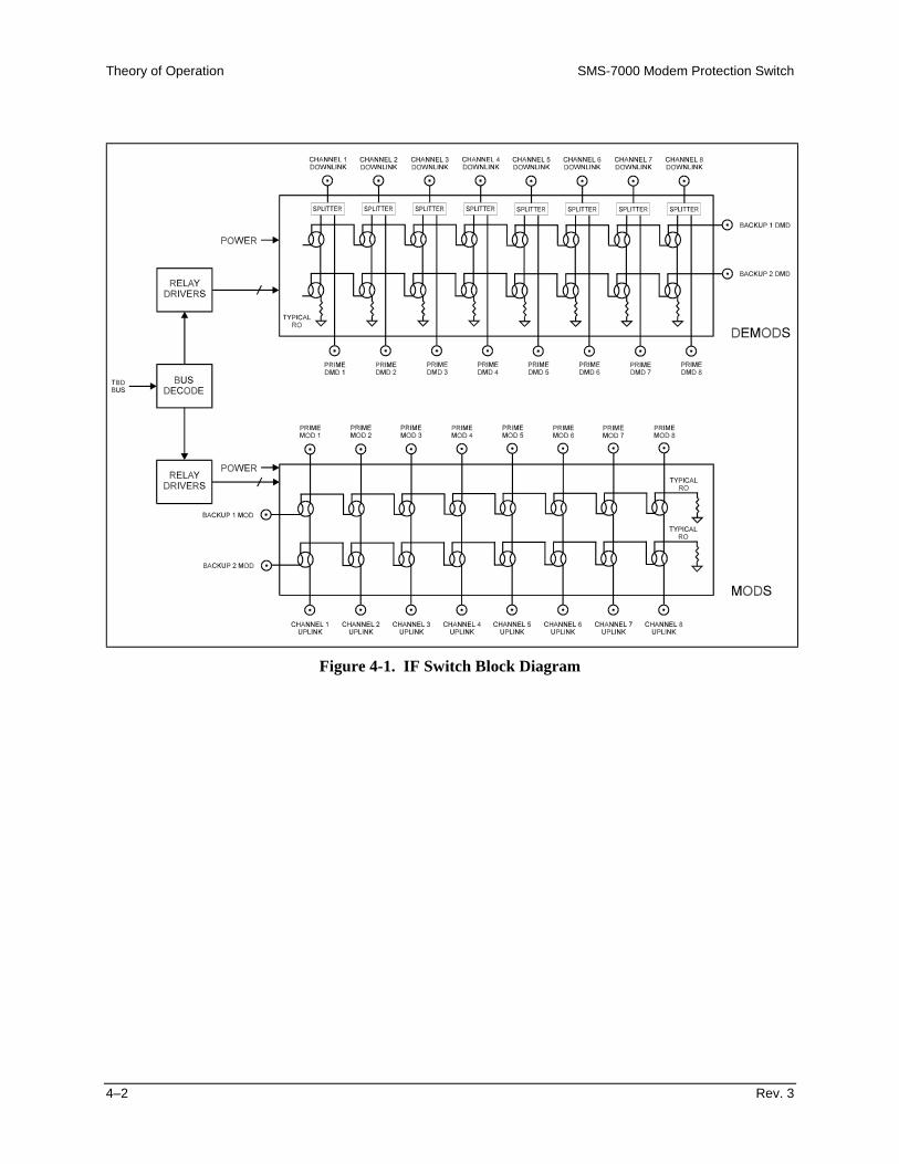
Theory of Operation SMS-7000 Modem Protection Switch
4–2 Rev. 3
Figure 4-1. IF Switch Block Diagram
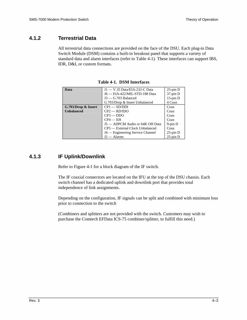
SMS-7000 Modem Protection Switch Theory of Operation
Rev. 3 4–3
4.1.2 Terrestrial Data
All terrestrial data connections are provided on the face of the DSU. Each plug-in DataSwitch Module (DSM) contains a built-in breakout panel that supports a variety ofstandard data and alarm interfaces (refer to Table 4-1). These interfaces can support IBS,IDR, D&I, or custom formats.
Table 4-1. DSM Interfaces
Data J1 — V.35 Data/EIA-232-C DataJ6 — EIA-422/MIL-STD-188 DataJ3 — G.703 BalancedG.703/Drop & Insert Unbalanced
25-pin D37-pin D15-pin D4 Coax
G.703/Drop & InsertUnbalanced
CP1 — SD/DDICP2 — RD/IDOCP3 — DDOCP4 — IDIJ5 — ADPCM Audio or 64K OH DataCP5 — External Clock UnbalancedJ4 — Engineering Service ChannelJ2 — Alarms
CoaxCoaxCoaxCoax9-pin DCoax25-pin D25-pin D
4.1.3 IF Uplink/Downlink
Refer to Figure 4-1 for a block diagram of the IF switch.
The IF coaxial connectors are located on the IFU at the top of the DSU chassis. Eachswitch channel has a dedicated uplink and downlink port that provides totalindependence of link assignments.
Depending on the configuration, IF signals can be split and combined with minimum lossprior to connection to the switch
(Combiners and splitters are not provided with the switch. Customers may wish topurchase the Comtech EFData ICS-75 combiner/splitter, to fulfill this need.)

Theory of Operation SMS-7000 Modem Protection Switch
4–4 Rev. 3
4.1.4 Monitors
Three connectors provide switch status and fault information on the rear of the SCUchassis (refer to Table 4-2).
Table 4-2. SCU Chassis Connectors
Switch FaultsJ3 System, Equipment, and Stored Faults 9-pin D
Online StatusJ6 Indicates whether prime modulators are on or offline 25-pin DJ5 Indicates whether prime demodulators are on or offline 25-pin D
Each set of fault output pins is isolated from internal switch electronics through single-pole and double-throw relays. The three contacts of each relay are provided to the userfor direct application of visual and audio indicators. Relay contacts will support 1 mA ofcontinuous current at up to 30 VDC.
Normally open (NO) pins are connected to common (COM) for non-faulted indicationsand online conditions. There is, however, one exception: the switch “COMMONEQUIPMENT” fault has the normally closed (NC) contact connected to the common(COM) for a no-fault condition (relay normally energized). This ensures that a fault isindicated in the event of switch power loss.

SMS-7000 Modem Protection Switch Theory of Operation
Rev. 3 4–5
4.1.5 Modem Interfaces
Connectors on the modem side of the DSU and IFU chassis provide direct pin-for-pindata connections to the applicable Comtech EFData modems.
A connector on the rear of the SCU provides remote and switch control of the modemsassociated with the switch. Table 4-3 lists the SCU rear panel connector information.
Table 4-3. SCU Rear Panel Connectors
Connector Function Type UnitJ1 to J10 Data 50-pin D DSUCP17 to CP36 RX and TX signals BNC IFUJ2 Modem remote 9-pin D SCU
The signal pin assignments of each channel depend on the configuration of the attachedprime modem. When commanded to load, the switch queries each prime modem for itsdata configuration. It then configures the breakout panels of each DSM accordingly. Thebreakout panels then switch the appropriate terrestrial data signals to the modem dataconnectors.
When placed online, the backup connectors (J9 and J10) reflect the connectors of theprime that is offline. The IF TX and RX signals (CP17 through CP36) are the remainingmodem interface signals. These are located at the rear of the IF chassis and arenumerically associated with their respective prime or backup modems.

Theory of Operation SMS-7000 Modem Protection Switch
4–6 Rev. 3
4.2 Switching Modes
Three distinct modem configurations facilitate the function of both independent anddependent backup configurations:
• Dependent RX/TX — Both RX and TX functions are switched regardless of RXor TX prime fault.
• Independent RX — Only RX functions are switched with a prime RX fault—TXfunctions are not affected.
• Independent TX — Only TX functions are switched with a prime TX fault—RXfunctions are not affected.
The two switching modes are discussed in Sections 4.2.1 and 4.2.2.
4.2.1 Manual Mode
The Manual switching mode allows the operator to replace any prime modem with anybackup modem to transmit functions, receive functions, or both (modem fault conditionshave no effect). For switching without operator intervention, the switch must be in Automode.
Prior to placing a backup online, the switch configures the backup modem to match theconfiguration of the designated prime.
The system is normally set up with the switch in Manual mode. After the configurationparameters have been entered into the switch and modems, a “Load All” command isgiven to the switch. The switch then queries the modems for their configurations.
4.2.2 Auto Mode
In Auto mode one or two redundancy configurations may be defined by associatingparticular prime modems to a single backup modem. For example, a dual 1:4configuration will have four different primes assigned to each of the two backupmodems.
Priority level assignments are assigned by the user in the modem configuration menus.The switching algorithm resolves priority by considering all primes in a configuration bytheir priority level.

SMS-7000 Modem Protection Switch Theory of Operation
Rev. 3 4–7
The prime modem with the lowest channel slot will have a backup modem in hot standbyif all of the priorities are set to the same level. This does not mean that it is a firmpriority level, it simply means that if no priorities are selected, then the switch mustplace the backup modem in standby for one of the modems. The first modem in thesystem is the logical choice.
It is important for the user to determine priority levels for the prime modems in order toachieve the desired switching results.
The switch will initially configure available backup modems in a standby conditionbased on channel priority assignments. This provides the operator with immediaterecovery for critical service channels. Afterwards, the switch continually monitors theTX and RX fault status of the prime and backup modems.
Whenever a fault(s) is registered, the switch will configure and place online anynonfaulted backup according to priorities. The remaining backup, if any, will be placedin a standby condition for the highest priority non-faulted channel.
Switching requirements are itemized as follows:
• Backup (BU) modems when turned on (enabled in configuration) will resolvethemselves (via the AUTO switching logic) to be either in the Standby (STBY)or Online condition.
Note: There is one exception for the 2:1 switch configuration: just one of thetwo BUs will be in the STBY or the Online condition.
• BU Standby modem service will migrate (via the switching logic) to the highestpriority non-faulted primes when BU modems are not Online.
• BU Online modem service will migrate (via the switching logic) to the highestpriority faulted primes at the expense of Standby service.
• If a BU modem is not faulted and is in a STBY condition for a faulted primeready for backup, the backup will be switched Online.
• A faulted prime that has priority will be assigned a non-faulted BU modem inSTBY prior to the BU being placed Online.
• A faulted prime that has priority will be assigned a BU modem already online fora lower priority prime. This occurs at the expense of the lower priority prime ifanother backup is not available.

Theory of Operation SMS-7000 Modem Protection Switch
4–8 Rev. 3
This page is intentionally left blank.

Rev. 3 5–1
5Chapter 5. MAINTENANCE
This chapter provides maintenance and troubleshooting information.
5.1 Periodic Maintenance
There is no periodic maintenance required to ensure proper switch operation.
5.2 Software Revisions
Installation of revised controller software may be necessary at times for implementingadditions or enhancing features and/or corrective actions. Control software resides in aprogrammable device inside the one unit (1U) switch control chassis (AS/4800). Toreplace software:
CAUTION
When replacing the switch software, the previous switch configuration andloaded modem configurations will be lost.
1. Disconnect switch power.
2. Disconnect and remove switch controller from equipment rack.
3. Remove top cover fasteners and cover.
4. Remove and replace U30 on printed circuit assembly AS/4518. U30 is asocketed device.

Maintenance SMS-7000 Modem Protection Switch
5–2 Rev. 3
5. Replace cover and fasteners.
6. Install and interconnect switch controller in rack.
7. Reconnect power to switch.
8. Perform a hard reset under the Utility/System menu.
9. Enter desired switch configuration.
10. Load all modems from Load/Verify menu or remote terminal.
11. Resume Auto mode, as required.
5.3 Fault Action
Corrective action should be taken whenever a fault is indicated. This action will guardagainst total switch failure and/or possible loss of service because of faulted primemodems.
5.3.1 Modem
Modem modulator and demodulator faults are reported by the switch as part of theoverall configuration status. The details of modem faults are available from theindividual modem fault menus. Refer to the appropriate modem installation andoperation manual for corrective action.
To replace a faulted modem:
1. Disconnect power from the faulted modem.
Notes:1. If the faulted modem is backed up by a backup modem in Dependent
mode, the backup modem will remain online without interruption ofservice.
2. If the faulted modem modulator or demodulator is backed up by a backupmodem in Independent mode, disconnecting power will switch thepreviously unfaulted side of the modem to an available backup modem.
2. Set the switch operation mode to Manual, then turn off the modulator anddemodulator of the faulted modem.

SMS-7000 Modem Protection Switch Maintenance
Rev. 3 5–3
3. Replace the faulted modem with a properly functioning modem. Power up thereplacement modem, and configure the modem exactly as the faulted modem wasconfigured.
4. On the switch, turn on the modulator and demodulator for the modem that hasbeen replaced. Verify the replaced modem’s communication and configurationsfrom the Load/Verify menu.
Note: A no-system fault condition ensures that the modem was correctlyconfigured and is communicating to the switch. (See Table 5-1 for fault analysis,if a fault exists.)
5. Set the switch operation mode back to Auto.
5.3.2 Switch
All faults reported in the switch fault menus (other than modem modulator anddemodulator faults) require corrective action to the switch or associatedinterconnections.
Table 5-1 lists the switch faults along with brief descriptions of fault mechanisms andchecks/actions. If multiple faults occur, the common symptom listed in the “Action”column will be the source of the fault.
Note: It is recommended that power be removed from the switch when changing out thedata switch modules.
Table 5-1. Switch Fault Analysis
Fault Description ActionMODEM COMM FAILURE Modem fails to respond to switch
commands on the modem remote bus,J2, of the SCU.
Verify modem agrees with switchconfiguration.If single modem failure, checkmodem connector or modem.If multiple modem failure, checkmodem remote cable.If all modem failure, check switchconnector or SCU.
MOD CONFIG VERIFY ERROR Results from inconsistencies betweenconfiguration stored in switch andconfiguration reported by modem.
Reload modem configuration fromLoad/Verify menu.
DMOD CONFIG ERROR Results from inconsistencies betweenconfiguration stored in switch andconfiguration reported by modem.
Reload modem configuration fromLoad/Verify menu.
NO ADDRESS FOR MODEM Address in configuration menu set to 0. Enter correct modem address.
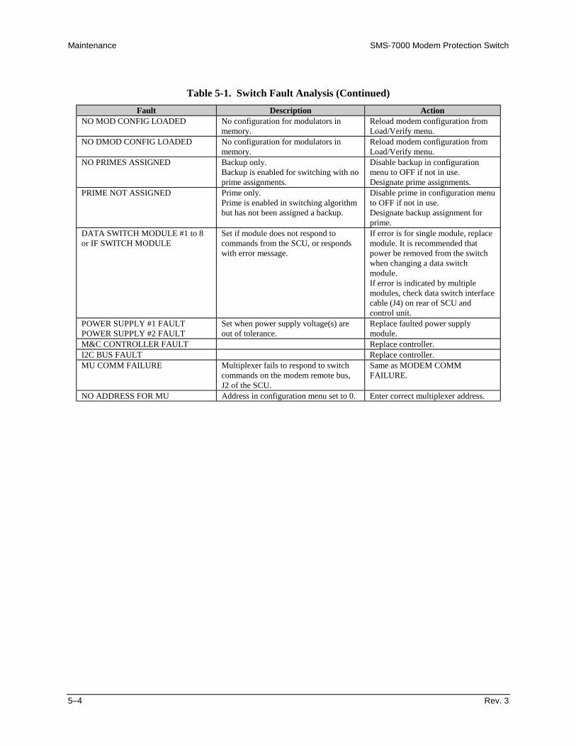
Maintenance SMS-7000 Modem Protection Switch
5–4 Rev. 3
Table 5-1. Switch Fault Analysis (Continued)
Fault Description ActionNO MOD CONFIG LOADED No configuration for modulators in
memory.Reload modem configuration fromLoad/Verify menu.
NO DMOD CONFIG LOADED No configuration for modulators inmemory.
Reload modem configuration fromLoad/Verify menu.
NO PRIMES ASSIGNED Backup only.Backup is enabled for switching with noprime assignments.
Disable backup in configurationmenu to OFF if not in use.Designate prime assignments.
PRIME NOT ASSIGNED Prime only.Prime is enabled in switching algorithmbut has not been assigned a backup.
Disable prime in configuration menuto OFF if not in use.Designate backup assignment forprime.
DATA SWITCH MODULE #1 to 8or IF SWITCH MODULE
Set if module does not respond tocommands from the SCU, or respondswith error message.
If error is for single module, replacemodule. It is recommended thatpower be removed from the switchwhen changing a data switchmodule.If error is indicated by multiplemodules, check data switch interfacecable (J4) on rear of SCU andcontrol unit.
POWER SUPPLY #1 FAULTPOWER SUPPLY #2 FAULT
Set when power supply voltage(s) areout of tolerance.
Replace faulted power supplymodule.
M&C CONTROLLER FAULT Replace controller.I2C BUS FAULT Replace controller.MU COMM FAILURE Multiplexer fails to respond to switch
commands on the modem remote bus,J2 of the SCU.
Same as MODEM COMMFAILURE.
NO ADDRESS FOR MU Address in configuration menu set to 0. Enter correct multiplexer address.

Rev. 3 Draft A–1
AAppendix A. REMOTE CONTROL OPERATION
This appendix describes the remote control operation of the switch.
• Firmware number: FW/4958-1J• Software version: 2.1.8
A.1 General
The remote controls and status for the switch are based on the SMS-658 and SMS-758redundancy switches to facilitate the use of existing control code to the extent possible.Due to unique and advanced features of the switch, there are differences, additions, anddeletions from the former command set. These changes are highlighted in bold type in thecomparison chart, Table A-1.
Remote controls and status information are transferred via a 2-/4-wire EIA-485 (optionalEIA-232) serial communications link.
Commands and data are transferred on the remote control communications link asUS ASCII-encoded character strings.
The remote communications link is operated in a half-duplex mode at baud rates from 110to 19200 bit/s.
Communications on the remote link are initiated by a remote controller or terminal. Theswitch never transmits data on the link unless it is commanded.
Command and status parameter selection will be determined by whether the backup modemswitching mode has been configured as Independent or Dependent. The switch will defaultto Independent mode after a cold startup or hard reset.

Remote Control Operation SMS-7000 Modem Protection Switch
A–2 Rev. 3 Draft
Table A-1. SMS-7000 Remote Control: SMS-658/SMS-758 Comparison Table
Command SMS-7000 SMS-658 SMS-758 NotesBackup Modem Address ADD_Bx_yyy ADD_Bx_yyy ADD_Bx_yyyBackup Mod Active MA_Bx_yyy MA_Bx_yyy MA_Bx_yyyBackup Demod Active DA_Bx_yyy DA_Bx_yyy DA_Bx_yyySwitching Mode Selection SM_Bx_yyy SMS-7000 onlyPrime Modem Assignments PMA_Bx_yyyyyyyy SMS-7000 onlyBackup Modem Interface Type INT_Bx_y INT_Bx_y SMS-658/SMS-758 onlyPrime Modem Interface Type INT_x_y INT_x_y SMS-658/SMS-758 onlyPrime Modem Address ADD_x_yyy ADD_x_yyy ADD_x_yyyPrime Mod Active MA_x_yyy MA_x_yyy MA_x_yyyPrime Demod Active DA_x_yyy DA_x_yyy DA_x_yyyPrime Mod Priority MP_x_y MP_x_y MP_x_yPrime Demod Priority DP_x_y DP_x_y DP_x_yPrime Modem Priority MP_x_y MP_x_y MP_x_yPrime Mod Online Delay MD_x_yyy.y MD_x_yyy.y MD_x_yyy.yPrime Demod Online Delay DD_x_yyy.y DD_x_yyy.y DD_x_yyy.yPrime Modem Online Delay MD_x_yyy.y MD_x_yyy.y MD_x_yyy.yMod Transponder MT_x_y SMS-658 onlyDemod Transponder DT_x_y DT_x_y SMS-658/SMS-758 onlyDownlink Transponder Option DTO_x SMS-758 onlyLoad Backup Modem Config LMC_Bx LMC_Bx LMC_Bx Limited responseLoad Prime Modem Config LMC_x LMC_x LMC_x Limited responseLoad All Modem Configs LMC_ALL LMC_ALL LMC_ALL Limited responseVerify Backup Modem Config VMC_Bx VMC_Bx VMC_Bx Limited responseVerify Prime Modem Config VMC_x VMC_x VMC_x Limited responseVerify All Modem Configs VMC_ALL VMC_ALL VMC_ALL Limited responseDrop and Insert G.703 Data DID_n_xxxxx SMS-7000 onlyExternal Clock ECLK_n_xxxxx SMS-7000 onlyInsert Data Input IDI_n_xxxx SMS-7000 onlyTime of Day TIME_hh:mmxx TIME_hh:mmxx TIME_hh:mmxxDate DATE_mm/dd/yy DATE_mm/dd/yy DATE_mm/dd/yyModem Control Baud Rate MBR_mmmmm SMS-7000 onlyRemote Operation REM_ SMS-7000 onlyClear Stored Faults CLSF_ SMS-7000 onlyOperational Mode MODE_xxxxxx MODE_xxxxxx MODE_xxxxxx Different parameters/responseBackup Mod Online Offline MOL_Bx_y MOL_Bx_y MOL_Bx_yBackup Demod Online Offline DOL_Bx_y DOL_Bx_y DOL_Bx_yBackup Modem Online Offline MOL_Bx_y MOL_Bx_y MOL_Bx_yBackup Mod Config Status MCS_Bn MCS_Bn MCS_Bn Different responseBackup Demod Config Status DCS_Bn DCS_Bn DCS_Bn Different responsePrime Mod Config Status MCS_n MCS_n MCS_n Different responsePrime Demod Config Status DCS_n DCS_n DCS_n Different responseModulator Status MS_ MS_ MS_Demodulator Status DS_ DS_ DS_Backup Modem Fault Status MFS_Bn MFS_Bn MFS_BnPrime Modem Fault Status MFS_n MFS_n MFS_nTX Operational Faults TOFS_ SMS-7000 onlyRX Operational Faults ROFS_ SMS-7000 onlyBackup Modem System Faults SFS_Bn SMS-7000 onlyPrime Modem System Faults SFS_n SMS-7000 onlyEquipment Fault Status EFS_ SMS-7000 onlyM:N Switch Fault Status MNF_ MNF_ MNF_ Different responseMod Operational Faults MOF_ MOF_ SMS-658/SMS-758 onlyDemod Operational Faults DOF_ DOF_ SMS-658/SMS-758 onlyMissing Parameter Faults MPF_ MPF_ SMS-658/SMS-758 only

SMS-7000 Modem Protection Switch Remote Control Operation
Rev. 3 Draft A–3
Table A-1. SMS-7000 Remote Control: SMS-658/SMS-758 Comparison Table (Continued)
Command SMS-7000 SMS-658 SMS-758 NotesTX Operational Stored Faults TOSF_# SMS-7000 onlyRX Operational Stored Faults ROSF_# SMS-7000 onlyBackup Modem System Stored Faults SSF_Bn_# SMS-7000 onlyPrime Modem System Stored Faults SSF_n_# SMS-7000 onlyEquipment Stored Faults ESF_# SMS-7000 onlyBulk Consolidated Status Faults BCSF_ BCSF_ BCSF_ Different responseEquipment Type ET_ ET_ ET_ Different responseM&C Firmware Information MCFI_ SMS-7000 onlyData Switch Module Firmware Info DMFI_ SMS-7000 onlyIF Switch Module Firmware Info IMFI_ SMS-7000 onlyFirmware Version Status VER_ VER_ SMS-658/SMS-758 onlyBackup Multiplexer Attached MU_Bx_yyy SMS-7000 onlyBackup Multiplexer Address MUA_Bx_yyy MUA_Bx_yyy MUA_Bx_yyyPrime Multiplexer Attached MU_x_yyy SMS-7000 onlyPrime Multiplexer Unit Address MUA_x_yyy MUA_x_yyy MUA_x_yyy
A.2 Message Structure
The ASCII character format used requires 11 bits/character:
• 1 start bit• 7 information bits• 1 parity bit• 2 stop bits
or• 1 start bit• 8 information bits• no parity bit• 2 stop bits
Messages on the remote link fall into the categories of commands and responses:
• Commands are messages which are transmitted to a switch• Responses are messages returned by a switch in response to a command
The general message structure is as follows:
• Start Character• Device Address• Command/Response• End of Message Character

Remote Control Operation SMS-7000 Modem Protection Switch
A–4 Rev. 3 Draft
A.2.1 Start Characters
A single character precedes all messages transmitted on the remote link. This characterflags the start of a message, as follows:
• “<” for commands• “>” for switch responses, or “>>” for modem responses through the
switch.A.2.2 Device Address
The device address is the address of the one switch or modem which is designated toreceive a transmitted command, or which is responding to a command.
Valid device addresses are 1 to 3 characters long, and in the range of 1 to 255. Address 0 isreserved as a global address which simultaneously addresses all devices on a givencommunications link. Devices do not acknowledge global commands.
Each switch which is connected to a common remote communications link must beassigned its own unique address. Addresses are front panel software selectable, and must bein the range between 1 to 255.
A.2.2 Command/Response
The command/response portion of the message contains a variable-length charactersequence which conveys command and response data.
If the switch receives a message addressed to it which does not match the establishedprotocol or cannot be implemented, a negative acknowledgment message is sent inresponse. This message is:
• >add/?ER2_invalid parameter'cr''lf'](Error message for a recognized command which cannot be implemented or has parameterswhich are out of range.)
• >add/?ER3_unrecognizable command'cr''lf'](Error message for unrecognizable command or bad command syntax.)
• >add/?ER4_switch not in remote mode'cr''lf'](Switch not in remote error; use the REM command to go to remote mode.)
• >add/?ER5_hard coded parameter'cr''lf'](Error message indicating that the parameter is hardware dependent and may not be changedremotely.)
• >add/?ER6_busy'cr''lf'](Error message indicating that the command sent cannot be carried out because localprocessing is utilizing the modem control bus.)

SMS-7000 Modem Protection Switch Remote Control Operation
Rev. 3 Draft A–5
Notes:1. “add” is used to indicate a valid 1 to 3 character device address in the range
between 1 and 255.2. The switch does not respond to erred communications (i.e., parity and
framing errors).
A.2.3 End Character
Each message is ended with a single character which signals the end of the message.This character is:
• “cr” Carriage return character for commands• “]” End bracket for responses
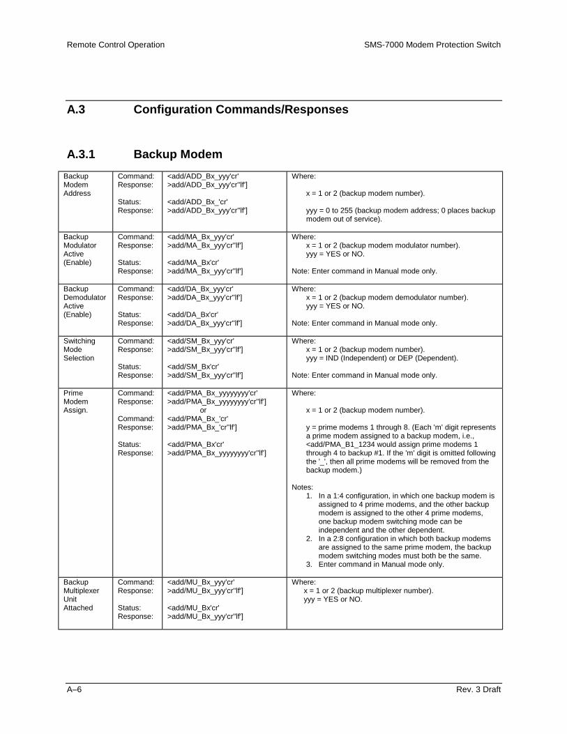
Remote Control Operation SMS-7000 Modem Protection Switch
A–6 Rev. 3 Draft
A.3 Configuration Commands/Responses
A.3.1 Backup Modem
BackupModemAddress
Command:Response:
Status:Response:
<add/ADD_Bx_yyy'cr'>add/ADD_Bx_yyy'cr''lf']
<add/ADD_Bx_'cr'>add/ADD_Bx_yyy'cr''lf']
Where:
x = 1 or 2 (backup modem number).
yyy = 0 to 255 (backup modem address; 0 places backupmodem out of service).
BackupModulatorActive(Enable)
Command:Response:
Status:Response:
<add/MA_Bx_yyy'cr'>add/MA_Bx_yyy'cr''lf']
<add/MA_Bx'cr'>add/MA_Bx_yyy'cr''lf']
Where:x = 1 or 2 (backup modem modulator number).yyy = YES or NO.
Note: Enter command in Manual mode only.
BackupDemodulatorActive(Enable)
Command:Response:
Status:Response:
<add/DA_Bx_yyy'cr'>add/DA_Bx_yyy'cr''lf']
<add/DA_Bx'cr'>add/DA_Bx_yyy'cr''lf']
Where:x = 1 or 2 (backup modem demodulator number).yyy = YES or NO.
Note: Enter command in Manual mode only.
SwitchingModeSelection
Command:Response:
Status:Response:
<add/SM_Bx_yyy'cr'>add/SM_Bx_yyy'cr''lf']
<add/SM_Bx'cr'>add/SM_Bx_yyy'cr''lf']
Where:x = 1 or 2 (backup modem number).yyy = IND (Independent) or DEP (Dependent).
Note: Enter command in Manual mode only.
PrimeModemAssign.
Command:Response:
Command:Response:
Status:Response:
<add/PMA_Bx_yyyyyyyy'cr'>add/PMA_Bx_yyyyyyyy'cr''lf']
or<add/PMA_Bx_'cr'>add/PMA_Bx_'cr''lf']
<add/PMA_Bx'cr'>add/PMA_Bx_yyyyyyyy'cr''lf']
Where:
x = 1 or 2 (backup modem number).
y = prime modems 1 through 8. (Each 'm' digit representsa prime modem assigned to a backup modem, i.e.,<add/PMA_B1_1234 would assign prime modems 1through 4 to backup #1. If the 'm' digit is omitted followingthe '_', then all prime modems will be removed from thebackup modem.)
Notes:1. In a 1:4 configuration, in which one backup modem is
assigned to 4 prime modems, and the other backupmodem is assigned to the other 4 prime modems,one backup modem switching mode can beindependent and the other dependent.
2. In a 2:8 configuration in which both backup modemsare assigned to the same prime modem, the backupmodem switching modes must both be the same.
3. Enter command in Manual mode only.
BackupMultiplexerUnitAttached
Command:Response:
Status:Response:
<add/MU_Bx_yyy'cr'>add/MU_Bx_yyy'cr''lf']
<add/MU_Bx'cr'>add/MU_Bx_yyy'cr''lf']
Where:x = 1 or 2 (backup multiplexer number).yyy = YES or NO.

SMS-7000 Modem Protection Switch Remote Control Operation
Rev. 3 Draft A–7
BackupMultiplexerUnit Address
Command:Response:
Status:Response:
<add/MUA_Bx_yyy'cr'>add/MUA_Bx_yyy'cr''lf']
<add/MUA_Bx'cr'>add/MUA_Bx_yyy'cr''lf']
Where:
x = 1 or 2 (backup multiplexer number).
yyy = 0 to 255 (backup multiplexer address; 0 placesbackup multiplexer out of service).
A.3.2 Prime Modem
PrimeModemAddress
Command:Response:
Status:Response:
<add/ADD_x_yyy'cr'>add/ADD_x_yyy'cr''lf']
<add/ADD_n_'cr'>add/ADD_n_yyy'cr''lf']
Where:
x = 1 to 8 (prime modem number).
yyy = 0 to 255 (prime modem address; 0 places primemodem out of service).
PrimeModulatorActive(Enable)
Command:Response:
Status:Response:
<add/MA_x_yyy'cr'>add/MA_x_yyy'cr''lf']
<add/MA_x'cr'>add/MA_x_yyy'cr''lf']
Where:x = 1 to 8 (prime modem modulator number).yyy = YES or NO.
Note: Enter command in Manual mode only.
PrimeDemodulator Active(Enable)
Command:Response:
Status:Response:
<add/DA_x_yyy'cr'>add/DA_x_yyy'cr''lf']
<add/DA_x'cr'>add/DA_x_yyy'cr''lf']
Where:x = 1 to 8 (prime modem demodulator number).yyy = YES or NO.
Note: Enter command in Manual mode only.
PrimeModulatorPriority
Command:Response:
Status:Response:
<add/MP_x_y'cr'>add/MP_x_y'cr''lf']
<add/MP_x'cr'>add/MP_x_y'cr''lf']
Where:x = 1 to 8 (prime modem modulator number).y = 1 (HIGH), 2 (MEDIUM), or 3 (LOW).
Note: Independent switching mode.
PrimeDemodulator Priority
Command:Response:
Status:Response:
<add/DP_x_y'cr'>add/DP_x_y'cr''lf']
<add/DP_x'cr'>add/DP_x_y'cr''lf']
Where:x = 1 to 8 (prime modem demodulator number).y = 1 (HIGH), 2 (MEDIUM), or 3 (LOW).
Note: Independent switching mode.
PrimeModemPriority
Command:Response:
Status:Response:
<add/MP_x_y'cr'>add/MP_x_y'cr''lf']
<add/MP_x'cr'>add/MP_x_y'cr''lf']
Where:x = 1 to 8 (prime modem number).y = 1 (HIGH), 2 (MEDIUM), or 3 (LOW).
Note: Dependent switching mode.
PrimeModulatorOn-lineDelay
Command:Response:
Status:Response:
<add/MD_x_yyy.y'cr'>add/MD_x_yyy.y'cr''lf']
<add/MD_x'cr'>add/MD_x_yyy.y'cr''lf']
Where:
x = 1 to 8 (prime modem modulator number).
NONE, or MANUAL.
yyy.y = 0.5 to 127.0 seconds (in 0.5 second increments).
Notes:1. If MANUAL is selected, enter the number of seconds for
the delay.2. Independent switching mode.

Remote Control Operation SMS-7000 Modem Protection Switch
A–8 Rev. 3 Draft
PrimeDemodulator On-lineDelay
Command:Response:
Status:Response:
<add/DD_x_yyy.y'cr'>add/DD_x_yyy.y'cr''lf']
<add/DD_x'cr'>add/DD_x_yyy.y'cr''lf']
Where:
x = 1 to 8 (prime modem demodulator number).
NONE, AUTO, or MANUAL.
yyy.y = 0.5 to 127.0 seconds (in 0.5 second increments).
Notes:1. If AUTO is selected, switching occurs after a delay
period of 2.5 minutes.2. If MANUAL is selected, enter the number of seconds for
the delay period.3. Independent switching mode.
PrimeModem On-line Delay
Command:Response:
Status:Response:
<add/MD_x_yyy.y'cr'>add/MD_x_yyy.y'cr''lf']
<add/MD_x'cr'>add/MD_x_yyy.y'cr''lf']
Where:
x = 1 to 8 (prime modem number).
yyy.y = 0.5 to 127.0 seconds (in 0.5 second increments),NONE, or AUTO.
Notes:1. If AUTO is selected, the delay is two times the sweep
period.2. Dependent switching mode.
PrimeMultiplexerUnitAttached
Command:Response:
Status:Response:
<add/MU_x_yyy'cr'>add/MU_x_yyy'cr''lf']
<add/MU_x'cr'>add/MU_x_yyy'cr''lf']
Where:x = 1 to 8 (prime multiplexer number).yyy = YES or NO.
PrimeMultiplexerUnitAddress
Command:Response:
Status:Response:
<add/MUA_x_yyy'cr'>add/MUA_x_yyy'cr''lf']
<add/MUA_x'cr'>add/MUA_x_yyy'cr''lf']
Where:
x = 1 to 8 (prime multiplexer number).
yyy = 0 to 255 (Prime multiplexer address; 0 places primemultiplexer out of service).
A.3.3 Switch
LoadBackupModem X
Command:Response:
<add/LMC_Bx'cr'>add/LMC_Bx'cr''lf']
Where: x = 1 or 2 (backup modem number).
Note: Status can be polled after operation by using the MNF_or BCSF_ commands.
LoadPrimeModem X
Command:Response:
<add/LMC_x'cr'>add/LMC_x'cr''lf']
Where: x = 1 or 8 (prime modem number).
Note: Status can be polled after operation by using the MNF_command.
Load AllModems
Command:Response:
<add/LMC_ALL'cr'>add/LMC_ALL'cr''lf']
Notes:1. This command will load all active backup modem and
prime modem configurations.2. Status can be polled after operation by using the MNF_
command.
VerifyBackupModem X
Command:Response:
<add/VMC_Bx'cr'>add/VMC_Bx'cr''lf']
Where: x = 1 or 2 (backup modem number).
Note: Status can be polled after operation by using the MNF_command.

SMS-7000 Modem Protection Switch Remote Control Operation
Rev. 3 Draft A–9
VerifyPrimeModem X
Command:Response:
<add/VMC_x'cr'>add/VMC_x'cr''lf']
Where: x = 1 or 8 (prime modem number).
Note: Status can be polled after operation by using the MNF_command.
Verify AllModems
Command:Response:
<add/VMC_ALL'cr'>add/VMC_ALL'cr''lf']
Notes:1. This command will verify all active backup and prime
modem configurations match those stored in the switch.2. Status can be polled after operation by using the MNF_
command.
A.3.4 Breakout
Drop andInsertG.703 Data
Command:Response:
Status:Response:
<add/DID_n_xxxxx'cr'>add/DID_n_xxxxx'cr''lf']
<add/DID_n'cr'>add/DID_n_xxxxx'cr''lf']
Where:n = 1 to 8 (prime channel number).xxxxx = BAL (Balanced) or UNBAL (Unbalanced).
ExternalClock
Command:Response:
Status:Response:
<add/ECLK_n_xxxxx'cr'>add/ECLK_n_xxxxx'cr''lf']
<add/ECLK_n'cr'>add/ECLK_n_xxxxx'cr''lf']
Where:n = 1 to 8 (prime channel number).xxxxx = BAL (Balanced) or UNBAL (Unbalanced).
Insert DataInput
Command:Response:
Status:Response:
<add/IDI_n_xxxx'cr'>add/IDI_n_xxxx'cr''lf']
<add/IDI_n'cr'>add/IDI_n_xxxx'cr''lf']
Where:n = 1 to 8 (prime channel number).xxxx = LOOP or NORM (for NORMAL).
A.3.5 System
Time of Day Command:Response:
Status:Response:
<add/TIME_hh:mmxx'cr'>add/TIME_hh:mmxx'cr''lf']
<add/TIME_'cr'>add/TIME_hh:mmxx'cr''lf']
Where:hh = 1 to 12 (hours).mm = 00 to 59 (minutes).xx = AM or PM.
Date Command:Response:
Status:Response:
<add/DATE_mm/dd/yy'cr'>add/DATE_mm/dd/yy'cr''lf']
<add/DATE_'cr'>add/DATE_mm/dd/yy'cr''lf']
Where:mm = 1 to 12 (month).dd = 1 to 31 (day).yy = 00 to 99 (year).
ModemControlBaud Rate
Command:Response:
Status:Response:
<add/MBR_mmmmm'cr'>add/MBR_mmmmm'cr''lf']
<add/MBR_'cr'>add/MBR_mmmmm'cr''lf']
Where: mmmmm = 9600 or 19200.
Note: Enter command in Manual mode only.
RemoteOperation
Command:Response:
<add/REM_'cr'>add/REM_'cr''lf']
Notes:1. Configures the SMS-7000 for remote operation.2. The SMS-7000 will respond to any status request at
any time. However, the SMS-7000 must be in Remotemode to change configuration parameters remotely.
ClearStoredFaults
Command:Response:
<add/CLSF_'cr'>add/CLSF_'cr''lf']
This command is used to clear all stored faults logged by theSMS-7000.

Remote Control Operation SMS-7000 Modem Protection Switch
A–10 Rev. 3 Draft
A.3.6 Mode
OperationalMode
Command:Response:
Status:Response:
<add/MODE_xxxxxx'cr'>add/MODE_xxxxxx'cr''lf']
<add/MODE_'cr'>add/MODE_xxxxxx'cr''lf']
Where: xxxxxx = AUTO or MANUAL.
Notes:1. This command selects the mode of operation for the
SMS-7000.2. If AUTO is selected, the M&C in the SMS-7000
controls all switching decisions.3. If MANUAL is selected, the operator controls all
switching decisions via the following three commands.
Set BackupModulator,On-line/Off-line(Manualmode,Independent Switching)
Command:Response:
Status:Response:
<add/MOL_Bx_y'cr'>add/MOL_Bx_y'cr''lf']
<add/MOL_Bx'cr'>add/MOL_Bx_y'cr''lf']
Where:
x = 1 or 2 (backup modem modulator number).
y = 0 to 8 (prime modem modulator number 1 through 8; 0takes backup modulator offline).
Notes:1. This command places specified backup modem
modulator online or offline for the specified primemodem modulator.
2. Enter command in Manual mode only.
Set BackupDemod.,On-line/Off-line(Manualmode,Independent Switching)
Command:Response:
Status:Response:
<add/DOL_Bx_y'cr'>add/DOL_Bx_y'cr''lf']
<add/DOL_Bx'cr'>add/DOL_Bx_y'cr''lf']
Where:
x = 1 or 2 (backup modem demodulator number).
y = 0 to 8 (prime modem demodulator number 1 through 8;0 takes backup modulator offline).
Notes:1. This command places specified backup modem
demodulator online or offline for the specified primemodem demodulator.
2. Enter command in Manual mode only.
Set BackupModem,Online/Offline(Manualmode,DependentSwitching)
Command:Response:
Status:Response:
<add/MOL_Bx_y'cr'>add/MOL_Bx_y'cr''lf']
<add/MOL_Bx'cr'>add/MOL_Bx_y'cr''lf']
Where:
x = 1 or 2 (backup modem number).
y = 0 to 8 (prime modem number 1 through 8; 0 takesbackup modem offline).
Notes:1. This command places specified backup modem online
or offline for the specified prime modem.2. Enter command in Manual mode only.

SMS-7000 Modem Protection Switch Remote Control Operation
Rev. 3 Draft A–11
A.4 Status Commands/Responses
BackupModulatorConfig.Status
Command:Response:
<add/MCS_Bn'cr'>add/MCS_Bn'cr'MA_xxx'cr'ADD_mmm'cr'SM_xxx'cr'PMA_mmmmmmmm'cr'MU_xxx'cr'MUA_mmm'cr''lf'] (See Note)
Where: n = 1 or 2 (backup modem number).
Modulator Active (YES/NO)Modem AddressSwitching Mode (IND/DEP)Prime Modem AssignmentsMultiplexer Unit Attached (YES/NO)Multiplexer Unit Address
The backup modulator configuration status commandcauses a block of data to be returned by the SMS-7000. Theblock of data reflects the stored configuration of the backupmodem selected.
Note: Status only returned if multiplexer unit attached.
BackupDemodulator Config.Status
Command:Response:
<add/DCS_Bn'cr'>add/DCS_Bn'cr'DA_xxx'cr'ADD_mmm'cr'SM_xxx'cr'PMA_mmmmmmmm'cr'MU_xxx'cr'MUA_mmm'cr''lf'] (See Note)
Where: n = 1 or 2 (backup modem number).
Demodulator Active (YES/NO)Modem AddressSwitching Mode (IND/DEP)Prime Modem AssignmentsMultiplexer Unit Attached (YES/NO)Multiplexer Unit Address
The backup demodulator configuration status commandcauses a block of data to be returned by the SMS-7000. Theblock of data reflects the stored configuration of the backupmodem selected.
Note: Status only returned if multiplexer unit is attached.
PrimeModulatorConfig.Status
Command:Response:
<add/MCS_n'cr'>add/MCS_n'cr'MA_yyy'cr'MP_y'cr'MD_yyy.y'cr'ADD_mmm'cr'MU_xxx'cr'MUA_mmm'cr' (See Note)DID_xxxxx'cr'ECLK_xxxxx'cr'IDI_xxxx'cr''lf']
Where: n = 1 to 8 (prime modem number).
Modulator Active (YES/NO)Modulator/Modem PriorityModulator/Modem DelayModem AddressMultiplexer Unit Attached (YES/NO)Multiplexer Unit AddressDrop & Insert Data (BAL/UNBAL)External Clock (BAL/UNBAL)Insert Data Input (LOOP/NORM)
The prime modulator configuration status command causesa block of data to be returned by the SMS-7000. The blockof data reflects the stored configuration of the prime modemselected.
Note: Status only returned if multiplexer unit is attached.

Remote Control Operation SMS-7000 Modem Protection Switch
A–12 Rev. 3 Draft
PrimeDemodulator Config.Status
Command:Response:
<add/DCS_n'cr'>add/DCS_n'cr'DA_yyy'cr'DP_y'cr' (Note 1)MP_y'cr' (Note 2)DD_yyy.y'cr' (Note 1)MD_yyy.y'cr' (Note 2)ADD_mmm'cr'MU_xxx'cr'MUA_mmm'cr' (Note 3)DID_xxxxx'cr'ECLK_xxxxx'cr'IDI_xxxx'cr''lf']
Where: n = 1 to 8 (prime modem number).
Demodulator Active (YES/NO)Demodulator PriorityModem PriorityDemodulator DelayModem DelayModem AddressMultiplexer Unit Attached (YES/NO)Multiplexer Unit AddressDrop & Insert Data (BAL/UNBAL)External Clock (BAL/UNBAL)Insert Data Input (LOOP/NORM)
The prime demodulator configuration status commandcauses a block of data to be returned by the SMS-7000. Theblock of data reflects the stored configuration of the primemodem selected.
Notes:1. Status only returned in Independent Mode.2. Status only returned in Dependent Mode.3. Status only returned if multiplexer unit is attached.
ModulatorStatus
Command:Response:
<add/MS_'cr'>add/MS_'cr'MOD_1_xxx'cr'MOD_2_xxx'cr'MOD_3_xxx'cr'MOD_4_xxx'cr'MOD_5_xxx'cr'MOD_6_xxx'cr'MOD_7_xxx'cr'MOD_8_xxx'cr'MOD_B1_xxx'cr'MOD_B2_xxx'cr''lf']
Prime #1 Modulator Status (OK/FLT)Prime #2 Modulator Status (OK/FLT)Prime #3 Modulator Status (OK/FLT)Prime #4 Modulator Status (OK/FLT)Prime #5 Modulator Status (OK/FLT)Prime #6 Modulator Status (OK/FLT)Prime #7 Modulator Status (OK/FLT)Prime #8 Modulator Status (OK/FLT)Backup #1 Modulator Status (OK/FLT)Backup #2 Modulator Status (OK/FLT)
The modulator status is returned as a block of data whichprovides fault information of all 'active' backup and primemodulators.
Note: Response shown is for a system with all possiblebackup modulators and prime modulators active. Onlyactive modulator status will be reported.
Demodulator Status
Command:Response:
<add/DS_'cr'>add/DS_'cr'DMD_1_xxx'cr'DMD_2_xxx'cr'DMD_3_xxx'cr'DMD_4_xxx'cr'DMD_5_xxx'cr'DMD_6_xxx'cr'DMD_7_xxx'cr'DMD_8_xxx'cr'DMD_B1_xxx'cr'DMD_B2_xxx'cr''lf']
Prime #1 Demodulator Status (OK/FLT)Prime #2 Demodulator Status (OK/FLT)Prime #3 Demodulator Status (OK/FLT)Prime #4 Demodulator Status (OK/FLT)Prime #5 Demodulator Status (OK/FLT)Prime #6 Demodulator Status (OK/FLT)Prime #7 Demodulator Status (OK/FLT)Prime #8 Demodulator Status (OK/FLT)Backup #1 Demodulator Status (OK/FLT)Backup #2 Demodulator Status (OK/FLT)
The demodulator status is returned as a block of data whichprovides fault information of all 'active' backup and primedemodulators.
Note: Response shown is for a system with all possiblebackup demodulators and prime demodulators active. Onlyactive demodulator status will be reported.

SMS-7000 Modem Protection Switch Remote Control Operation
Rev. 3 Draft A–13
BackupModemFault StatusSummary
Command:Response:
<add/MFS_Bn'cr'>add/MFS_Bn'cr'MOD_xxx'cr'DMD_xxx'cr''lf']
Where: n = 1 or 2 (backup modem number).
Modulator Status (OK/FLT)Demodulator Status (OK/FLT)
PrimeModemFault StatusSummary
Command:Response:
<add/MFS_n'cr'>add/MFS_n'cr'MOD_xxx'cr'DMD_xxx'cr''lf']
Where: n = 1 to 8 (prime modem number).
Modulator Status (OK/FLT)Demodulator Status (OK/FLT)
TransmitOperationalFaultsStatus
Command:Response:
<add/TOFS_'cr'>add/TOFS_'cr'MOD_1_xxx'cr'MOD_2_xxx'cr'MOD_3_xxx'cr'MOD_4_xxx'cr'MOD_5_xxx'cr'MOD_6_xxx'cr'MOD_7_xxx'cr'MOD_8_xxx'cr'SFLT_xx'cr''lf']
Prime #1 TX Operational Status (OK/FLT)Prime #2 TX Operational Status (OK/FLT)Prime #3 TX Operational Status (OK/FLT)Prime #4 TX Operational Status (OK/FLT)Prime #5 TX Operational Status (OK/FLT)Prime #6 TX Operational Status (OK/FLT)Prime #7 TX Operational Status (OK/FLT)Prime #8 TX Operational Status (OK/FLT)Number of Stored Faults Logged (0 through 10)
ReceiveOperationalFaultsStatus
Command:Response:
<add/ROFS_'cr'>add/ROFS_'cr'DMD_1_xxx'cr'DMD_2_xxx'cr'DMD_3_xxx'cr'DMD_4_xxx'cr'DMD_5_xxx'cr'DMD_6_xxx'cr'DMD_7_xxx'cr'DMD_8_xxx'cr'SFLT_xx'cr''lf']
Prime #1 RX Operational Status (OK/FLT)Prime #2 RX Operational Status (OK/FLT)Prime #3 RX Operational Status (OK/FLT)Prime #4 RX Operational Status (OK/FLT)Prime #5 RX Operational Status (OK/FLT)Prime #6 RX Operational Status (OK/FLT)Prime #7 RX Operational Status (OK/FLT)Prime #8 RX Operational Status (OK/FLT)Number of Stored Faults Logged (0 through 10)
BackupModemSystemFault StatusSummary
Command:Response:
<add/SFS_Bn'cr'>add/SFS_Bn'cr'COMM_xxx'cr'MOD_CONFIG_VFY_xxx'cr'DMD_CONFIG_VFY_xxx'cr'ADD_xxx'cr'MOD_CONFIG_LOAD_xxx'cr'DMD_CONFIG_LOAD_xxx'cr'PRIME_ASSIGNED_xxx'cr'MU_COMM_xxx'cr' (See Note)MU_ADD_xxx'cr' (See Note)SFLT_xx'cr''lf']
Where: n = 1 or 2 (backup modem number).
Modem Communications (OK/FLT)Modulator Config Verify (OK/FLT)Demodulator Config Verify (OK/FLT)Backup Modem Address (OK/FLT)Modulator Config Loaded (OK/FLT)Demodulator Config Loaded (OK/FLT)Primes Assigned to Backup (OK/FLT)Multiplexer Unit Communications (OK/FLT)Multiplexer Unit Address (OK/FLT)Number of Stored Faults Logged (0 through 10)
Note: Status only returned if multiplexer unit is attached.
PrimeModemSystemFault StatusSummary
Command:Response:
<add/SFS_n'cr'>add/SFS_n'cr'COMM_xxx'cr'MOD_CONFIG_VFY_xxx'cr'DMD_CONFIG_VFY_xxx'cr'ADD_xxx'cr'MOD_CONFIG_LOAD_xxx'cr'DMD_CONFIG_LOAD_xxx'cr'PRIMES_ASSIGNMENT_xxx'cr'MU_COMM_xxx'cr' (See Note)MU_ADD_xxx'cr' (See Note)SFLT_xx'cr''lf']
Where: n = 1 to 8 (prime modem number).
Modem Communications (OK/FLT)Modulator Config Verify (OK/FLT)Demodulator Config Verify (OK/FLT)Prime Modem Address (OK/FLT)Modulator Config Loaded (OK/FLT)Demodulator Config Loaded (OK/FLT)Prime Assigned to Backup (OK/FLT)Multiplexer Unit Communications (OK/FLT)Multiplexer Unit Address (OK/FLT)Number of Stored Faults Logged (0 through 10)
Note: Status only returned if multiplexer unit is attached.
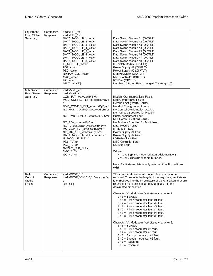
Remote Control Operation SMS-7000 Modem Protection Switch
A–14 Rev. 3 Draft
EquipmentFault StatusSummary
Command:Response:
<add/EFS_'cr'>add/EFS_'cr'DATA_MODULE_1_xxx'cr'DATA_MODULE_2_xxx'cr'DATA_MODULE_3_xxx'cr'DATA_MODULE_4_xxx'cr'DATA_MODULE_5_xxx'cr'DATA_MODULE_6_xxx'cr'DATA_MODULE_7_xxx'cr'DATA_MODULE_8_xxx'cr'IF_MODULE_xxx'cr'PS1_xxx'cr'PS2_xxx'cr'NVRAM_CLK_xxx'cr'M&C_xxx'cr'I2C_xxx'cr'SFLT_xx'cr''lf']
Data Switch Module #1 (OK/FLT)Data Switch Module #2 (OK/FLT)Data Switch Module #3 (OK/FLT)Data Switch Module #4 (OK/FLT)Data Switch Module #5 (OK/FLT)Data Switch Module #6 (OK/FLT)Data Switch Module #7 (OK/FLT)Data Switch Module #8 (OK/FLT)IF Switch Module (OK/FLT)Power Supply #1 (OK/FLT)Power Supply #2 (OK/FLT)NVRAM/Clock (OK/FLT)M&C Controller (OK/FLT)I2C Bus (OK/FLT)Number of Stored Faults Logged (0 through 10)
M:N SwitchFault StatusSummary
Command:Response:
<add/MNF_'cr'>add/MNF_'cr'COM_FLT_xxxxxxxxByBy'cr'MOD_CONFIG_FLT_xxxxxxxxByBy'cr'DMD_CONFIG_FLT_xxxxxxxByBy'cr'NO_MOD_CONFIG_xxxxxxxxByBy'cr'NO_DMD_CONFIG_xxxxxxxxByBy'cr'NO_ADX_xxxxxxxByBy'cr'NOT_ASSIGNED_xxxxxxxxByBy'cr'MU_COM_FLT_xxxxxxxxByBy'cr'NO_MU_ADX_xxxxxxxxByBy'cr'DATA_MODULE_FLT_xxxxxxxx'cr'IF_MODULE_FLT'cr'PS1_FLT'cr'PS2_FLT'crNVRAM_CLK_FLT'cr'M&C_FLT'cr'I2C_FLT'cr''lf']
Modem Communications FaultsMod Config Verify FaultsDemod Config Verify FaultsNo Mod Configuration LoadedNo Demod Configuration LoadedNo Address Specified for ModemPrime Assignment FaultMux Communications FaultsNo Address Specified for MultiplexerData Module FaultsIF Module FaultPower Supply #1 FaultPower Supply #2 FaultNVRAM/Clock FaultM&C Controller FaultI2C Bus Fault
Where:x = 1 to 8 (prime modem/data module number).y = 1 or 2 (backup modem number).
Note: Fault status data is only returned if fault conditionsexist.
BulkConsol.StatusFaults
Command:Response:
<add/BCSF_'cr'>add/BCSF_'a''b''c'...'y''z''aa''ab''ac''ad''ae''cr''lf']
This command causes all modem fault status to bereturned. To reduce the length of the response, fault statusis embedded into the bit structure of the characters that arereturned. Faults are indicated by a binary 1 in thedesignated bit position.
Character 'a': Modulator fault status character 1.Bit 6 = 1 always.Bit 5 = Prime modulator fault #1 fault.Bit 4 = Prime modulator fault #2 fault.Bit 3 = Prime modulator fault #3 fault.Bit 2 = Prime modulator fault #4 fault.Bit 1 = Prime modulator fault #5 fault.Bit 0 = Prime modulator fault #6 fault.
Character 'b': Modulator fault status character 2.Bit 6 = 1 always.Bit 5 = Prime modulator #7 fault.Bit 4 = Prime modulator #8 fault.Bit 3 = Backup modulator #1 fault.Bit 2 = Backup modulator #2 fault.Bit 1 = Reserved.Bit 0 = Reserved.
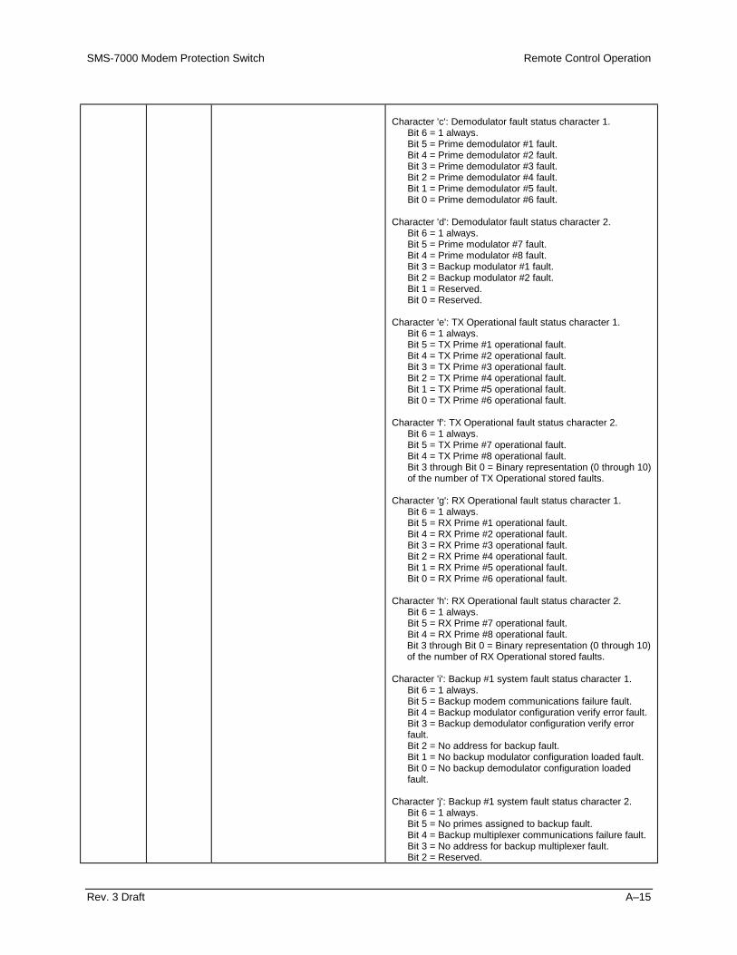
SMS-7000 Modem Protection Switch Remote Control Operation
Rev. 3 Draft A–15
Character 'c': Demodulator fault status character 1.Bit 6 = 1 always.Bit 5 = Prime demodulator #1 fault.Bit 4 = Prime demodulator #2 fault.Bit 3 = Prime demodulator #3 fault.Bit 2 = Prime demodulator #4 fault.Bit 1 = Prime demodulator #5 fault.Bit 0 = Prime demodulator #6 fault.
Character 'd': Demodulator fault status character 2.Bit 6 = 1 always.Bit 5 = Prime modulator #7 fault.Bit 4 = Prime modulator #8 fault.Bit 3 = Backup modulator #1 fault.Bit 2 = Backup modulator #2 fault.Bit 1 = Reserved.Bit 0 = Reserved.
Character 'e': TX Operational fault status character 1.Bit 6 = 1 always.Bit 5 = TX Prime #1 operational fault.Bit 4 = TX Prime #2 operational fault.Bit 3 = TX Prime #3 operational fault.Bit 2 = TX Prime #4 operational fault.Bit 1 = TX Prime #5 operational fault.Bit 0 = TX Prime #6 operational fault.
Character 'f': TX Operational fault status character 2.Bit 6 = 1 always.Bit 5 = TX Prime #7 operational fault.Bit 4 = TX Prime #8 operational fault.Bit 3 through Bit 0 = Binary representation (0 through 10)of the number of TX Operational stored faults.
Character 'g': RX Operational fault status character 1.Bit 6 = 1 always.Bit 5 = RX Prime #1 operational fault.Bit 4 = RX Prime #2 operational fault.Bit 3 = RX Prime #3 operational fault.Bit 2 = RX Prime #4 operational fault.Bit 1 = RX Prime #5 operational fault.Bit 0 = RX Prime #6 operational fault.
Character 'h': RX Operational fault status character 2.Bit 6 = 1 always.Bit 5 = RX Prime #7 operational fault.Bit 4 = RX Prime #8 operational fault.Bit 3 through Bit 0 = Binary representation (0 through 10)of the number of RX Operational stored faults.
Character 'i': Backup #1 system fault status character 1.Bit 6 = 1 always.Bit 5 = Backup modem communications failure fault.Bit 4 = Backup modulator configuration verify error fault.Bit 3 = Backup demodulator configuration verify errorfault.Bit 2 = No address for backup fault.Bit 1 = No backup modulator configuration loaded fault.Bit 0 = No backup demodulator configuration loadedfault.
Character 'j': Backup #1 system fault status character 2.Bit 6 = 1 always.Bit 5 = No primes assigned to backup fault.Bit 4 = Backup multiplexer communications failure fault.Bit 3 = No address for backup multiplexer fault.Bit 2 = Reserved.

Remote Control Operation SMS-7000 Modem Protection Switch
A–16 Rev. 3 Draft
Bit 1 = Reserved.Bit 0 = Reserved.
Character 'k': Backup #1 system fault status character 3.Bit 6 = 1 always.Bit 5 = Reserved.Bit 4 = Reserved.Bit 3 through Bit 0 = Binary representation (0 through 10)of the number of Backup #1 system stored faults.
Character 'l': Backup #2 system fault status character 1.Bit 6 = 1 always.Bit 5 = Backup modem communications failure fault.Bit 4 = Backup modulator configuration verify error fault.Bit 3 = Backup demodulator configuration verify errorfault.Bit 2 = No address for backup fault.Bit 1 = No backup modulator configuration loaded fault.Bit 0 = No backup demodulator configuration loadedfault.
Character 'm': Backup #2 system fault status character 2.Bit 6 = 1 always.Bit 5 = No primes assigned to backup fault.Bit 4 = Backup multiplexer communications failure fault.Bit 3 = No address for backup multiplexer fault.Bit 2 = Reserved.Bit 1 = Reserved.Bit 0 = Reserved.
Character 'n': Backup #2 system fault status character 3.Bit 6 = 1 always.Bit 5 = Reserved.Bit 4 = Reserved.Bit 3 through Bit 0 = Binary representation (0 through 10)of the number of Backup #2 system stored faults.
Character 'o': Prime #1 system fault status character 1.Bit 6 = 1 always.Bit 5 = Prime modem communications failure fault.Bit 4 = Prime modulator configuration verify error fault.Bit 3 = Prime demodulator configuration verify error fault.Bit 2 = No address for prime fault.Bit 1 = No prime modulator configuration loaded fault.Bit 0 = No prime demodulator configuration loaded fault.
Character 'p': Prime #1 system fault status character 2.Bit 6 = 1 always.Bit 5 = Prime not assigned to backup fault.Bit 4 = Prime multiplexer communications failure fault.Bit 3 = No address for prime multiplexer fault.Bit 2 = Reserved.Bit 1 = Reserved.Bit 0 = Reserved.
Character 'q': Prime #1 system fault status character 3.Bit 6 = 1 always.Bit 5 = Reserved.Bit 4 = Reserved.Bit 3 through Bit 0 = Binary representation (0 through 10)of the number of Prime #1 system stored faults.
Character 'r': Prime #2 system fault status character 1.Bit 6 = 1 always.Bit 5 = Prime modem communications failure fault.Bit 4 = Prime modulator configuration verify error fault.Bit 3 = Prime demodulator configuration verify error fault.Bit 2 = No address for prime fault.Bit 1 = No prime modulator configuration loaded fault.

SMS-7000 Modem Protection Switch Remote Control Operation
Rev. 3 Draft A–17
Bit 0 = No prime demodulator configuration loaded fault.
Character 's': Prime #2 system fault status character 2.Bit 6 = 1 always.Bit 5 = Prime not assigned to backup fault.Bit 4 = Prime multiplexer communications failure fault.Bit 3 = No address for prime multiplexer fault.Bit 2 = Reserved.Bit 1 = Reserved.Bit 0 = Reserved.
Character 't': Prime #2 system fault status character 3.Bit 6 = 1 always.Bit 5 = Reserved.Bit 4 = Reserved.Bit 3 through Bit 0 = Binary representation (0 through 10)of the number of Prime #2 system stored faults.
Character 'u': Prime #3 system fault status character 1.Bit 6 = 1 always.Bit 5 = Prime modem communications failure fault.Bit 4 = Prime modulator configuration verify error fault.Bit 3 = Prime demodulator configuration verify error fault.Bit 2 = No address for prime fault.Bit 1 = No prime modulator configuration loaded fault.Bit 0 = No prime demodulator configuration loaded fault.
Character 'v': Prime #3 system fault status character 2.Bit 6 = 1 always.Bit 5 = Prime not assigned to backup fault.Bit 4 = Prime multiplexer communications failure fault.Bit 3 = No address for prime multiplexer fault.Bit 2 = Reserved.Bit 1 = Reserved.Bit 0 = Reserved.
Character 'w': Prime #3 system fault status character 3.Bit 6 = 1 always.Bit 5 = Reserved.Bit 4 = Reserved.Bit 3 through Bit 0 = Binary representation (0 through 10)of the number of Prime #3 system stored faults.
Character 'x': Prime #4 system fault status character 1.Bit 6 = 1 always.Bit 5 = Prime modem communications failure fault.Bit 4 = Prime modulator configuration verify error fault.Bit 3 = Prime demodulator configuration verify error fault.Bit 2 = No address for prime fault.Bit 1 = No prime modulator configuration loaded fault.Bit 0 = No prime demodulator configuration loaded fault.
Character 'y': Prime #4 system fault status character 2.Bit 6 = 1 always.Bit 5 = Prime not assigned to backup fault.Bit 4 = Prime multiplexer communications failure fault.Bit 3 = No address for prime multiplexer fault.Bit 2 = Reserved.Bit 1 = Reserved.Bit 0 = Reserved.
Character 'z': Prime #4 system fault status character 3.Bit 6 = 1 always.Bit 5 = Reserved.Bit 4 = Reserved.Bit 3 through Bit 0 = Binary representation (0 through 10)of the number of Prime #4 system stored faults.

Remote Control Operation SMS-7000 Modem Protection Switch
A–18 Rev. 3 Draft
Character 'aa': Prime #5 system fault status character 1.Bit 6 = 1 always.Bit 5 = Prime modem communications failure fault.Bit 4 = Prime modulator configuration verify error fault.Bit 3 = Prime demodulator configuration verify error fault.Bit 2 = No address for prime fault.Bit 1 = No prime modulator configuration loaded fault.Bit 0 = No prime demodulator configuration loaded fault.
Character 'ab': Prime #5 system fault status character 2.Bit 6 = 1 always.Bit 5 = Prime not assigned to backup fault.Bit 4 = Prime multiplexer communications failure fault.Bit 3 = No address for prime multiplexer fault.Bit 2 = Reserved.Bit 1 = Reserved.Bit 0 = Reserved.
Character 'ac': Prime #5 system fault status character 3.Bit 6 = 1 always.Bit 5 = Reserved.Bit 4 = Reserved.Bit 3 through Bit 0 = Binary representation (0 through 10)of the number of Prime #5 system stored faults.
Character 'ad': Prime #6 system fault status character 1.Bit 6 = 1 always.Bit 5 = Prime modem communications failure fault.Bit 4 = Prime modulator configuration verify error fault.Bit 3 = Prime demodulator configuration verify error fault.Bit 2 = No address for prime fault.Bit 1 = No prime modulator configuration loaded fault.Bit 0 = No prime demodulator configuration loaded fault.
Character 'ae': Prime #6 system fault status character 2.Bit 6 = 1 always.Bit 5 = Prime not assigned to backup fault.Bit 4 = Prime multiplexer communications failure fault.Bit 3 = No address for prime multiplexer fault.Bit 2 = Reserved.Bit 1 = Reserved.Bit 0 = Reserved.
Character 'af': Prime #6 system fault status character 3.Bit 6 = 1 always.Bit 5 = Reserved.Bit 4 = Reserved.Bit 3 through Bit 0 = Binary representation (0 through 10)of the number of Prime #6 system stored faults.
Character 'ag': Prime #7 system fault status character 1.Bit 6 = 1 always.Bit 5 = Prime modem communications failure fault.Bit 4 = Prime modulator configuration verify error fault.Bit 3 = Prime demodulator configuration verify error fault.Bit 2 = No address for prime fault.Bit 1 = No prime modulator configuration loaded fault.Bit 0 = No prime demodulator configuration loaded fault.
Character 'ah': Prime #7 system fault status character 2.Bit 6 = 1 always.Bit 5 = Prime not assigned to backup fault.Bit 4 = Prime multiplexer communications failure fault.Bit 3 = No address for prime multiplexer fault.Bit 2 = Reserved.Bit 1 = Reserved.

SMS-7000 Modem Protection Switch Remote Control Operation
Rev. 3 Draft A–19
Bit 0 = Reserved.Character 'ai': Prime #7 system fault status character 3.
Bit 6 = 1 always.Bit 5 = Reserved.Bit 4 = Reserved.Bit 3 through Bit 0 = Binary representation (0 through 10)of the number of Prime #7 system stored faults.
Character 'aj': Prime #8 system fault status character 1.Bit 6 = 1 always.Bit 5 = Prime modem communications failure fault.Bit 4 = Prime modulator configuration verify error fault.Bit 3 = Prime demodulator configuration verify error fault.Bit 2 = No address for prime fault.Bit 1 = No prime modulator configuration loaded fault.Bit 0 = No prime demodulator configuration loaded fault.
Character 'ak': Prime #8 system fault status character 2.Bit 6 = 1 always.Bit 5 = Prime not assigned to backup fault.Bit 4 = Prime multiplexer communications failure fault.Bit 3 = No address for prime multiplexer fault.Bit 2 = Reserved.Bit 1 = Reserved.Bit 0 = Reserved.
Character 'al': Prime #8 system fault status character 3.Bit 6 = 1 always.Bit 5 = Reserved.Bit 4 = Reserved.Bit 3 through Bit 0 = Binary representation (0 through 10)of the number of Prime #8 system stored faults.
Character 'am': Equipment fault status character 1.Bit 6 = 1 always.Bit 5 = Data Switch Module #1 fault.Bit 4 = Data Switch Module #2 fault.Bit 3 = Data Switch Module #3 fault.Bit 2 = Data Switch Module #4 fault.Bit 1 = Data Switch Module #5 fault.Bit 0 = Data Switch Module #6 fault.
Character 'an': Equipment fault status character 2.Bit 6 = 1 always.Bit 5 = Data Switch module #7 fault.Bit 4 = Data Switch module #8 fault.Bit 3 = IF Switch Module fault.Bit 2 = Power Supply #1 fault.Bit 1 = Power Supply #2 fault.Bit 0 = NVRAM/Clock fault.
Character 'ao': Equipment fault status character 3.Bit 6 = 1 always.Bit 5 = M&C Controller fault.Bit 4 = I2C fault.Bit 3 through Bit 0 = Binary representation (0 through 10)of the number of equipment stored faults.

Remote Control Operation SMS-7000 Modem Protection Switch
A–20 Rev. 3 Draft
A.5 Stored Faults
Information on stored faults is returned when requested. If no stored fault exists for agiven fault number, the words “NO Fault” will be returned instead of the normaltime/date status information.
The following symbols are commonly used to define the stored faults status commands:
• # Fault number (0 to 9). “0” is the first fault stored.• hh Hours in 24-hour format.• mm Minutes.• ss Seconds.• MM Month.• DD Day.• YY Year.
TransmitOperationalStoredFaults
Command:Response:
<add/TOSF_#'cr'>add/TOSF_#hh:mm:ssMM/DD/YY'cr'MOD_1_xxx'cr'MOD_2_xxx'cr'MOD_3_xxx'cr'MOD_4_xxx'cr'MOD_5_xxx'cr'MOD_6_xxx'cr'MOD_7_xxx'cr'MOD_8_xxx'cr''lf']
Prime #1 TX Operational Status (OK/FLT)Prime #2 TX Operational Status (OK/FLT)Prime #3 TX Operational Status (OK/FLT)Prime #4 TX Operational Status (OK/FLT)Prime #5 TX Operational Status (OK/FLT)Prime #6 TX Operational Status (OK/FLT)Prime #7 TX Operational Status (OK/FLT)Prime #8 TX Operational Status (OK/FLT)
ReceiveOperationalStoredFaults
Command:Response:
<add/ROSF_#'cr'>add/ROSF_#hh:mm:ssMM/DD/YY'cr'DMD_1_xxx'cr'DMD_2_xxx'cr'DMD_3_xxx'cr'DMD_4_xxx'cr'DMD_5_xxx'cr'DMD_6_xxx'cr'DMD_7_xxx'cr'DMD_8_xxx'cr''lf']
Prime #1 RX Operational Status (OK/FLT)Prime #2 RX Operational Status (OK/FLT)Prime #3 RX Operational Status (OK/FLT)Prime #4 RX Operational Status (OK/FLT)Prime #5 RX Operational Status (OK/FLT)Prime #6 RX Operational Status (OK/FLT)Prime #7 RX Operational Status (OK/FLT)Prime #8 RX Operational Status (OK/FLT)
BackupModemSystemStoredFaults
Command:Response:
<add/SSF_Bn_#'cr'>add/SSF_Bn_# hh:mm:ssMM/DD/YY'cr'COMM_xxx'cr'MOD_CONFIG_VFY_xxx'cr'DMD_CONFIG_VFY_xxx'cr'ADD_xxx'cr'MOD_CONFIG_LOAD_xxx'cr'DMD_CONFIG_LOAD_xxx'cr'PRIMES_ASSIGNED_xxx'cr''lf']MU_COMM_xxx'cr' (See Note)MU_ADD_xxx'cr''lf'] (See Note)
Where: n = 1 to 2 (backup modem number).
Modem Communications (OK/FLT)Modulator Config Verify (OK/FLT)Demodulator Config Verify (OK/FLT)Backup Modem Address (OK/FLT)Modulator Config Loaded (OK/FLT)Demodulator Config Loaded (OK/FLT)Primes Assigned to Backup (OK/FLT)Multiplexer Unit Communications (OK/FLT)Multiplexer Unit Address (OK/FLT)
Note: Status only returned if multiplexer unit is attached.

SMS-7000 Modem Protection Switch Remote Control Operation
Rev. 3 Draft A–21
PrimeModemSystemStoredFaults
Command:Response:
<add/SSF_n_#'cr'>add/SSF_n_# hh:mm:ssMM/DD/YY'cr'COMM_xxx'cr'MOD_CONFIG_VFY_xxx'cr'DMD_CONFIG_VFY_xxx'cr'ADD_xxx'cr'MOD_CONFIG_LOAD_xxx'cr'DMD_CONFIG_LOAD_xxx'cr'PRIME_ASSIGNMENT_xxx'cr'MU_COMM_xxx'cr' (See Note)MU_ADD_xxx'cr''lf'] (See Note)
Where: n = 1 to 8 (prime modem number).
Modem Communications (OK/FLT)Modulator Config Verify (OK/FLT)Demodulator Config Verify (OK/FLT)Prime Modem Address (OK/FLT)Modulator Config Loaded (OK/FLT)Demodulator Config Loaded (OK/FLT)Prime Assigned to Backup (OK/FLT)Multiplexer Unit Communications (OK/FLT)Multiplexer Unit Address (OK/FLT)
Note: Status only returned if multiplexer unit is attached.
EquipmentStoredFaults
Command:Response:
<add/ESF_#'cr'>add/ESF_# hh:mm:ss MM/DD/YY'cr'DATA_MODULE_1_xxx'cr'DATA_MODULE_2_xxx'cr'DATA_MODULE_3_xxx'cr'DATA_MODULE_4_xxx'cr'DATA_MODULE_5_xxx'cr'DATA_MODULE_6_xxx'cr'DATA_MODULE_7_xxx'cr'DATA_MODULE_8_xxx'cr'IF_MODULE_xxx'cr'PS1_xxx'cr'PS2_xxx'cr'NVRAM_CLK_xxx'cr'M&C_xxx'cr'I2C_xxx'cr''lf']
Data Switch Module #1 (OK/FLT)Data Switch Module #2 (OK/FLT)Data Switch Module #3 (OK/FLT)Data Switch Module #4 (OK/FLT)Data Switch Module #5 (OK/FLT)Data Switch Module #6 (OK/FLT)Data Switch Module #7 (OK/FLT)Data Switch Module #8 (OK/FLT)IF Switch Module (OK/FLT)Power Supply #1 (OK/FLT)Power Supply #2 (OK/FLT)NVRAM/Clock (OK/FLT)M&C Controller (OK/FLT)I2C Bus (OK/FLT)
A.6 About Switch
EquipmentType
Command:Response:
<add/ET_'cr'>add/ET_tttttttt_xxx.yyy.zzz'cr''lf']
Where:
tttttttt = Equipment type.
xxx.yyy.zzz = Software version number (0.0.0 to999.999.999).
This command returns the equipment type andsoftware version of the addressed device.
M&CFirmwareInformation
Command:Response:
<add/MCFI_'cr'>add/MCFI_'cr'VER_aaa.bbb.ccc'cr'FW/nnnnnn-zzr,mm/dd/yy'cr''lf']
Where:
aaa.bbb.ccc = Software version number (0.0.0 to999.999.999).
nnnnnn = Firmware number (0 to 99999).
zz = Firmware dash number (0 to 99).
r = Firmware revision (-, or A to Z).
mm = 1 to 12 (month).
dd = 1 to 31 (day).
yy = 00 to 99 (year).

Remote Control Operation SMS-7000 Modem Protection Switch
A–22 Rev. 3 Draft
Data SwitchModuleFirmwareInformation
Command:Response:
<add/DMFI_'cr'>add/DMFI_'cr'DM1_FW/nnnnnn-zzr,mm/dd/yy'cr'
or DM1_xxx'cr'DM2_FW/nnnnnn-zzr,mm/dd/yy'cr'
or DM2_xxx'cr'DM3_FW/nnnnnn-zzr,mm/dd/yy'cr'
or DM3_xxx'cr'DM4_FW/nnnnnn-zzr,mm/dd/yy'cr'
or DM4_xxx'cr'DM5_FW/nnnnnn-zzr,mm/dd/yy'cr'
or DM5_xxx'cr'DM6_FW/nnnnnn-zzr,mm/dd/yy'cr'
or DM6_xxx'cr'DM7_FW/nnnnnn-zzr,mm/dd/yy'cr'
or DM7_xxx'cr'DM8_FW/nnnnnn-zzr,mm/dd/yy'cr''lf']
or DM8_xxx'cr''lf']
Where:nnnnnn = Firmware number (0 to 99999).zz = Firmware dash number (0 to 99).r = Firmware revision (-, or A to Z).mm = 1 to 12 (month).dd = 1 to 31 (day).yy = 00 to 99 (year).xxx = N/A (not available).
IF SwitchModuleFirmwareInformation
Command:Response:
<add/IMFI_'cr'>add/IMFI_FW/nnnnnn-zzr,mm/dd/yy'cr''lf']
or>add/IMFI_xxx'cr''lf']
Where:nnnnnn = Firmware number (0 to 99999).zz = Firmware dash number (0 to 99).r = Firmware revision (-, or A to Z).mm = 1 to 12 (month).dd = 1 to 31 (day).yy = 00 to 99 (year).xxx = N/A (not available).
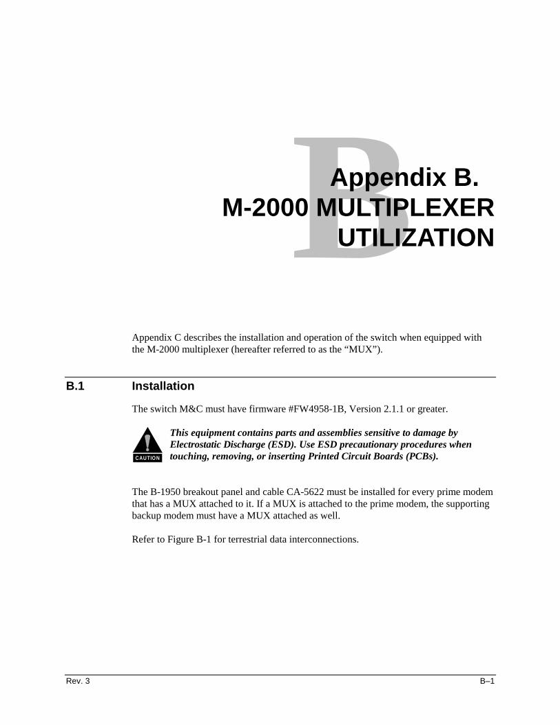
Rev. 3 B–1
BAppendix B. M-2000 MULTIPLEXER
UTILIZATION
Appendix C describes the installation and operation of the switch when equipped withthe M-2000 multiplexer (hereafter referred to as the “MUX”).
B.1 Installation
The switch M&C must have firmware #FW4958-1B, Version 2.1.1 or greater.
CAUTION
This equipment contains parts and assemblies sensitive to damage byElectrostatic Discharge (ESD). Use ESD precautionary procedures whentouching, removing, or inserting Printed Circuit Boards (PCBs).
The B-1950 breakout panel and cable CA-5622 must be installed for every prime modemthat has a MUX attached to it. If a MUX is attached to the prime modem, the supportingbackup modem must have a MUX attached as well.
Refer to Figure B-1 for terrestrial data interconnections.

M-2000-Multiplexer Utilization SMS-7000 Modem Protection Switch
B–2 Rev. 3
Figure B-1. Terrestrial Data Interconnections
Refer to Table B-1 for signal pinout information on the data switch module J6 connectorequipped with a MUX.
Note: The 8 kbit/s IDR overhead data channel can be directly connected to the primemultiplexer. The 8 kbit/s overhead will not be switched to the backup in the event of aprime modem and/or multiplexer failure.
Connect all multiplexers via Remote port (J5) to Modem Remote (J2) on the switchM&C with an EIA-485 2-wire cable. All multiplexers must be configured for EIA-485(2-wire), 9600 or 19200 baud with a unique address. Refer to the M-2000 MultiplexerInstallation and Operation Manual for further information on the MUX.

SMS-7000 Modem Protection Switch M-2000-Multiplexer Utilization
Rev. 3 B–3
Table B-1. SMS-7000/M-2000 50-Pin to 37-Pin Interface Cable Pinouts
50-Pin Signal Name 37-Pin1 Shield 1
37 CH2 SDA 438 CH2 SDB 2239 CH2 RDA 640 CH2 RDB 2421 CH3 SDA 522 CH3 SDB 2323 CH3 RDA 824 CH3 RDB 264 CH4 SDA 35 CH4 SDB 216 CH4 RDA 157 CH4 RDB 33
B.2 Operation
On the switch M&C Configuration menu, enable multiplexers by selecting YES on theMultiplexer submenu for each modem with a multiplexer. Enter a unique address foreach multiplexer. Load all modems and set Operation mode to Auto. Refer to Table 5-1for fault information. Refer to the M-2000 Multiplexer Installation and OperationManual for further operation information.
Note: To operate with the switch, the MUX must be configured with both transmit andreceive faults enabled (ON).

M-2000-Multiplexer Utilization SMS-7000 Modem Protection Switch
B–4 Rev. 3
This page is intentionally left blank.

Rev. 3 g–1
GGlossary
The following is a list of acronyms and abbreviations that may be found in this manual:
Acronym/Abbreviation
Definition
ADPCM Adaptive Differential Pulse Code ModulationASCII American Standard Code for Information InterchangeASGN Assign
ASYNC AsynchronousAUTO Automatic
BCKUP BackupBOP Break Out PanelBU Backup
BUS BussCH Channel
Coax CoaxialCOM Common
CONFIG ConfigurationD&I Drop and InsertDDI Drop Data InDDO Drop Data Out
Demod DemodulatorDep Dependent
DMD DemodulatorDSM Data Switch ModuleDSR Data Set ReadyDSU Data Switch Unit
CE-Mark Community Europe MarkEMI Electromagnetic InterferenceEXC External ClockFW FirmwareFEC Forward Error Correction
lf Line feedGND GroundHz Hertz (cycle per second)

Glossary SMS-7000 Modem Protection Switch
g–2 Rev. 3
I/O Input/OutputIBS INTELSAT Business ServicesIDI Insert Data InIDO Insert Data OutIDR Intermediate Data RateIF Intermediate Frequency
IFU Intermediate Frequency Switch UnitIND IndependentLCD Liquid Crystal DisplayLED Light-Emitting DiodeM&C Monitor and ControlMHz Megahertz (106 Hertz)Mod ModulatorNC Normally ClosedN/C No ConnectNO Normally OpenPC Personal Computer
PCB Printed Circuit BoardPWB Printed Wire BoardRD Receive Data
RLSD Receive Line Signal DetectRR Receiver ReadyRS Reed-SolomonRT Receive Timing
RTS Request to SendRX Receive (Receiver)
RXCLK Receive ClockSCR Serial Clock ReceiveSCT Serial Clock Transmit
SCTE Serial Clock Transmit ExternalSCU Switch Control UnitSD Send Data
SMS Satellite Multiservice SystemST Send Timing
STBY StandbySYS SystemTD Transmit DataTT Terminal TimingTX Transmit (Transmitter)
TXC Transmit ClockTXCLK Transmit Clock
TXD Transmit DataTXO TX OctetUS United States
VAC Volts, Alternating CurrentVDC Volts, Direct Current
Ver or VER VersionW Watt

Rev. 3 i–1
I Index
About Switch, A–21ADPCM Audio Data (J5), 2–32Alarms (J2), 2–31Auto Mode, 4–6Back Mount, 2–7Backup Modem, 3–2, A–2, A–3, A–6, A–8, A–10, A–13,
A–20Balanced G.703/Drop & Insert Data (J3), 2–33Breakout, 3–31, A–9Cabling the Unit, 2–13Command/Response, A–3, A–4Compatibility, 1–2, 1–3Configuration, 1–2, 1–12, 3–1, 3–5, 3–8, 3–9, 3–10, 3–11,
3–14, 3–15, 3–16, 3–17, 3–18, 3–19, 3–22, 3–23, 3–30,3–31, 4–1, A–6, A–14
Configuration Commands/Responses, A–6Data Formats, 1–4Data Switch Unit (DSU), 1–6, 1–9, 2–7Device Address, A–3, A–4DSU (J12) to IFU (J1), 2–16DSU Data Connections (J1 through J10), 2–20, 2–21DSU Terrestrial Data Interfaces, 2–26End Character, A–5Engineering Service Channel Data (J4), 2–30Fault Action, 5–2Fixed, 2–8Front Panel, 1–8, 1–12, 3–1, 3–2, 3–4Front Panel Controls, 3–4Hinged, 2–10IF Switch Unit (IFU), 1–11IF Uplink/Downlink, 4–3IFU Uplink and Downlink IF (CP1 through CP16), 2–35INSTALLATION, 2–1Interconnecting the Switch Components, 2–13Interfaces, 1–12, 1–13, 2–26, 4–1, 4–3
LED Indicators, 3–3
Load/Verify, 3–16, 3–17, 3–31, 5–2, 5–3, 5–4Manual Mode, 4–6Menu System, 3–5Message Structure, A–3Mode, 3–18, 3–19, 3–30, 3–32, A–2, A–6, A–10, A–11,
A–12Modem, 1–3, 1–10, 1–12, 2–23, 3–30, 3–31, 3–32, 4–1, 4–
5, 5–2, 5–3, A–2, A–3, A–6, A–7, A–8, A–9, A–10, A–11, A–12, A–13, A–14, A–20, A–21
Modem Interface, 4–5, A–2Modem Remote (J2) to all Modems, 2–23Monitors, 1–12, 4–4Mounting, 1–5, 2–7, 2–9, 2–11Operation Mode, 3–18, 3–19, 3–32Options, 1–5, 3–11, 3–12, 3–15, 3–29Overview, 1–2Periodic Maintenance, 5–1Prime Modem, 3–2, 3–30, A–2, A–3, A–7, A–8, A–9, A–
11, A–13, A–21SCU (J4) to DSU (J11) Interface, 2–15SCU Rear Panel, 1–8, 2–20, 2–22, 4–5Setup and Configuration, 3–30Software Revisions, 5–1Specifications, 1–12, 1–13Start Characters, A–4Status Commands/Responses, A–11Stored Faults, 3–5, 3–26, 3–27, 4–4, A–2, A–3, A–9, A–
13, A–14, A–20, A–21Switch, 1–1, 1–5, 1–6, 1–8, 1–9, 1–11, 1–12, 1–13, 2–7,
2–13, 2–23, 3–3, 3–25, 3–32, 4–2, 4–3, 4–4, 5–3, 5–4,A–3, A–4, A–8, A–14, A–19, A–21, A–22
Switch Faults (J3) to User, 2–23Switching Modes, 1–12, 4–6

Index SMS-7000 Modem Protection Switch
i–2 Rev. 3
Terrestrial Data, 1–13, 2–26, 2–27, 2–28, 2–29, 4–3THEORY OF OPERATION, 4–1Top Mount, 2–7, 2–9
Unbalanced Data Ports, 2–34Unpacking, 2–1User Interfaces, 2–22User Remote (J1), 2–22Utility Setup, 3–30
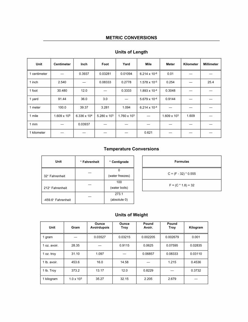
METRIC CONVERSIONS
Units of Length
Unit
Centimeter
Inch
Foot
Yard
Mile
Meter
Kilometer
Millimeter
1 centimeter — 0.3937 0.03281 0.01094 6.214 x 10⁻⁶ 0.01 — —
1 inch 2.540 — 0.08333 0.2778 1.578 x 10⁻⁵ 0.254 — 25.4
1 foot 30.480 12.0 — 0.3333 1.893 x 10⁻⁴ 0.3048 — —
1 yard 91.44 36.0 3.0 — 5.679 x 10⁻⁴ 0.9144 — —
1 meter 100.0 39.37 3.281 1.094 6.214 x 10⁻⁴ — — —
1 mile 1.609 x 10⁵ 6.336 x 10⁴ 5.280 x 10³ 1.760 x 10³ — 1.609 x 10³ 1.609 —
1 mm — 0.03937 — — — — — —
1 kilometer — — — — 0.621 — — —
Temperature Conversions
Units of Weight
Unit
Gram
Ounce Avoirdupois
Ounce Troy
Pound Avoir.
Pound Troy
Kilogram
1 gram — 0.03527 0.03215 0.002205 0.002679 0.001
1 oz. avoir. 28.35 — 0.9115 0.0625 0.07595 0.02835
1 oz. troy 31.10 1.097 — 0.06857 0.08333 0.03110
1 lb. avoir. 453.6 16.0 14.58 — 1.215 0.4536
1 lb. Troy 373.2 13.17 12.0 0.8229 — 0.3732
1 kilogram 1.0 x 10³ 35.27 32.15 2.205 2.679 —
Unit
° Fahrenheit
° Centigrade
32° Fahrenheit —
0
(water freezes)
212° Fahrenheit —
100
(water boils)
-459.6° Fahrenheit —
273.1
(absolute 0)
Formulas
C = (F - 32) * 0.555
F = (C * 1.8) + 32

2114 WEST 7TH STREET TEMPE ARIZONA 85281 USA 480 • 333 • 2200 PHONE
480 • 333 • 2161 FAX


