SMS Tutorials SRH-2D – Culvert Structures with HY-8 SRH-2D Tutorial Culvert Structures with HY-8 Objectives This tutorial demonstrates the process of modeling culverts in SRH-2D coupled with the Federal Highway Administrations HY-8 culvert analysis application. The “SRH-2D Simulations” tutorial should have been completed before attempting this one. All files for this tutorial are found in the “Input” folder within the “ SMS_SRH-2D_HY8_Culvert” tutorial folder. Prerequisites SMS Overview SRH-2D SRH-2D – Simulations Requirements SRH-2D Mesh Module Scatter Module Map Module SMS v. 13.0 Time 15–20 minutes
Transcript
SMS Tutorials SRH-2D – Culvert Structures with HY-8
Page 1 of 12 Page
SRH-2D Tutorial Culvert Structures with HY-8
Objectives
This tutorial demonstrates the process of modeling culverts in SRH-2D coupled with the Federal
Highway Administrations HY-8 culvert analysis application. The “SRH-2D Simulations” tutorial should
have been completed before attempting this one. All files for this tutorial are found in the “Input” folder
within the “ SMS_SRH-2D_HY8_Culvert” tutorial folder.
Prerequisites
SMS Overview
SRH-2D
SRH-2D – Simulations
Requirements
SRH-2D
Mesh Module
Scatter Module
Map Module
SMS v. 13.0
Time
15–20 minutes
SMS Tutorials SRH-2D – Culvert Structures with HY-8
Page 2 of 12 Page
1 Model Overview
An existing SRH-2D model will be used to facilitate the setup for this tutorial. SRH-2D
provides two different ways to define a culvert. One way couples the FHWA HY-8
culvert model with SRH-2D and the other way utilizes the culvert definition built into
SRH-2D. This tutorial will demonstrate the first method.
The area being modeled is located at the confluence of the west and middle forks of the
Gila River, located in New Mexico.
During high flows, a significant amount of water is backed up near one of the roadway
bridges causing flooding upstream. The purpose of this tutorial is to simulate a culvert
relief structure near the bridge to mitigate the flooding.
Although an HY-8 culvert structure is a capable option for modeling culverts, it is a 1D
calculation and any momentum calculated in the 2D computations will not be transferred
through the structure.
2 Getting Started
To begin, do the following:
1. Open a new instance of SMS.
2. Select File | Open to bring up the Open dialog.
3. Navigate to and select the “Gila_Structure.sms” project found in the / SMS_SRH-
2D_HY8_Culvert /Input folder for this tutorial.
4. Click Open to import the data.
In the Project Explorer, duplicates of the “ Regular Flow” simulation and “ BC”
coverage have been made to expedite the model setup process. The duplicates have been
renamed as “ Culvert Flow” and “ Culvert BC” respectively. The culvert structure
will be created within the “ Culvert BC” coverage and simulated in the “ Culvert
Flow” simulation.
The process of duplicating these items was demonstrated in the “SRH-2D Simulations”
tutorial. Creating duplicates of simulations or coverages allows making modifications to a
1 Model Overview .................................................................................................................... 2 2 Getting Started ...................................................................................................................... 2 3 Creating the Culvert Structure ............................................................................................ 3
3.1 Creating the Structure Arcs ............................................................................................ 4 3.2 Creating the HY-8 Culvert Definition File ..................................................................... 6 3.3 Assigning Culvert Structure Attributes in HY-8 ............................................................ 6
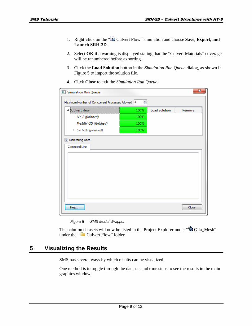
4 Saving, Exporting, and Launching the Simulation ............................................................ 8 5 Visualizing the Results .......................................................................................................... 9 6 Conclusion ........................................................................................................................... 12
SMS Tutorials SRH-2D – Culvert Structures with HY-8
Page 3 of 12 Page
model while still preserving the original simulation or coverages. This also enables
creating several modeling scenarios in the same project and compare the solutions.
1. In the Time steps window, scroll through the time steps and select the final time
interval at “0 02:30:00”.
The project should appear similar to Figure 1. Notice that the flow is overtopping the
roadway in the upper left part of the road.
Figure 1 Gila_Structure.sms project
The mesh datasets located under the “ Regular Flow” folder in the Project Explorer are
from an SRH-2D solution of the existing flow conditions, without the culvert relief
structure. The datasets can be used to make comparisons and visualize the effects the
culvert structure boundary condition will have on the model.
3 Creating the Culvert Structure
The culvert structure will be created near the bridge location (as shown in Figure 2).
Culvert structures are defined by creating two boundary condition arcs, one on the
upstream face and one on the downstream face of the structure. The boundary condition
arcs are then defined as a culvert structure and the attributes of the culvert are defined in
the HY-8 culvert definition dialog.
SMS Tutorials SRH-2D – Culvert Structures with HY-8
Page 4 of 12 Page
3.1 Creating the Structure Arcs
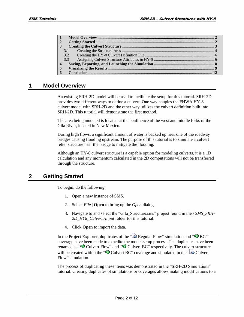
The first step for creating a culvert structure for SRH-2D is to create arcs representing the
structure within the SRH-2D boundary condition coverage.
Figure 2 Culvert location
1. Select the “ Z” dataset under “ Gila_Mesh” in the Project Explorer to display the
mesh elevations.
2. Use the Zoom tool to zoom into the culvert location near the bridge (Figure 2).
3. Select Display | Display Options… to open the Display Options dialog.
4. In the 2D Mesh section, check the box next to Elements to turn on the display of
mesh elements.
5. Select OK to exit the Display Options.
6. In the Project Explorer, check the box next to the “ Culvert BC” coverage and
select it to make it the active coverage.
SMS Tutorials SRH-2D – Culvert Structures with HY-8
Page 5 of 12 Page
7. Use the Create Feature Arc tool to create two arcs, one on each side of the road.
These arcs will define the upstream and downstream faces of the culvert structure.
The created arcs should be placed in the locations shown in Figure 3.
It is recommended that the mesh be created to contain quadrilateral elements within the
area between these two arcs which represent the culvert structure and that the structure
arcs are aligned with a clean row of element edges.
Note: When drawing these arcs, they should be drawn in the same direction. After the
first arc has been drawn, ensure that the second arc is drawn in the same direction (north
to south or south to north). Drawing them in opposing directions may cause an error
when running SRH-2D.
Figure 3 Upstream and Downstream BC Culvert Arcs
Culvert
Upstream Face
Culvert
Downstream Face
SMS Tutorials SRH-2D – Culvert Structures with HY-8
Page 6 of 12 Page
3.2 Creating the HY-8 Culvert Definition File
When running the model, SMS couples SRH-2D with HY-8. The HY-8 crossing
definition file must be created.
1. Right-click on the “ Culvert BC” coverage and select HY-8 Options… to
bring up the HY-8 Options dialog.
2. Click Select under HY-8 File to launch a file browser.
3. Navigate to the directory where the tutorial project file is stored (/ SMS_SRH-
2D_HY8_Culvert /Input).
4. Enter “Relief_Culvert.hy8” (be sure to include the “.hy8” extension) as the File
name.
5. Select Save to create the file and close the file browser.
6. Select OK to close the HY-8 Options dialog.
3.3 Assigning Culvert Structure Attributes in HY-8
The next step in creating the culvert structure is to specify the boundary condition type
and define the culvert attributes.
1. Using the Select Feature Arc tool, select the upstream (leftmost) culvert arc
and take note of the ID for this arc, which is displayed the Status Bar at the
bottom of the SMS application.
2. Hold the Shift key and select the downstream (right) culvert arc so that both of
the arcs are selected.
3. Right-click on either arc and select the Assign Linear BC... command. SMS will
bring up the SRH-2D Linear BC dialog.
4. In the Type combo box, select “Culvert HY-8”. Be sure to select “Culvert HY-8”
and not “Culvert”.
5. Note the assignment of “Culvert Upstream” and “Culvert Downstream” to the
two arcs, associated with their ID values. If the ID displayed for culvert upstream
is not the same as noted above in step 1, switch the associations using the combo
box for Role.
6. The Units can be left as “U.S. Customary”.
The Use total head option will add the velocity head to the water surface elevations for
the 1D culvert calculations. It will not be used for this application.
7. Select Launch HY-8 under HY-8 Culvert. This will open the HY-8 software.
8. In HY-8, right-click on “ Project”, in the HY-8 Project Explorer and choose
Add Culvert Crossing.
9. In the Crossing Data dialog, under Crossing Properties, change the Name to
“Gila Crossing” and under Culvert Data, change the Name to “Relief Culvert”.
SMS Tutorials SRH-2D – Culvert Structures with HY-8
Page 7 of 12 Page
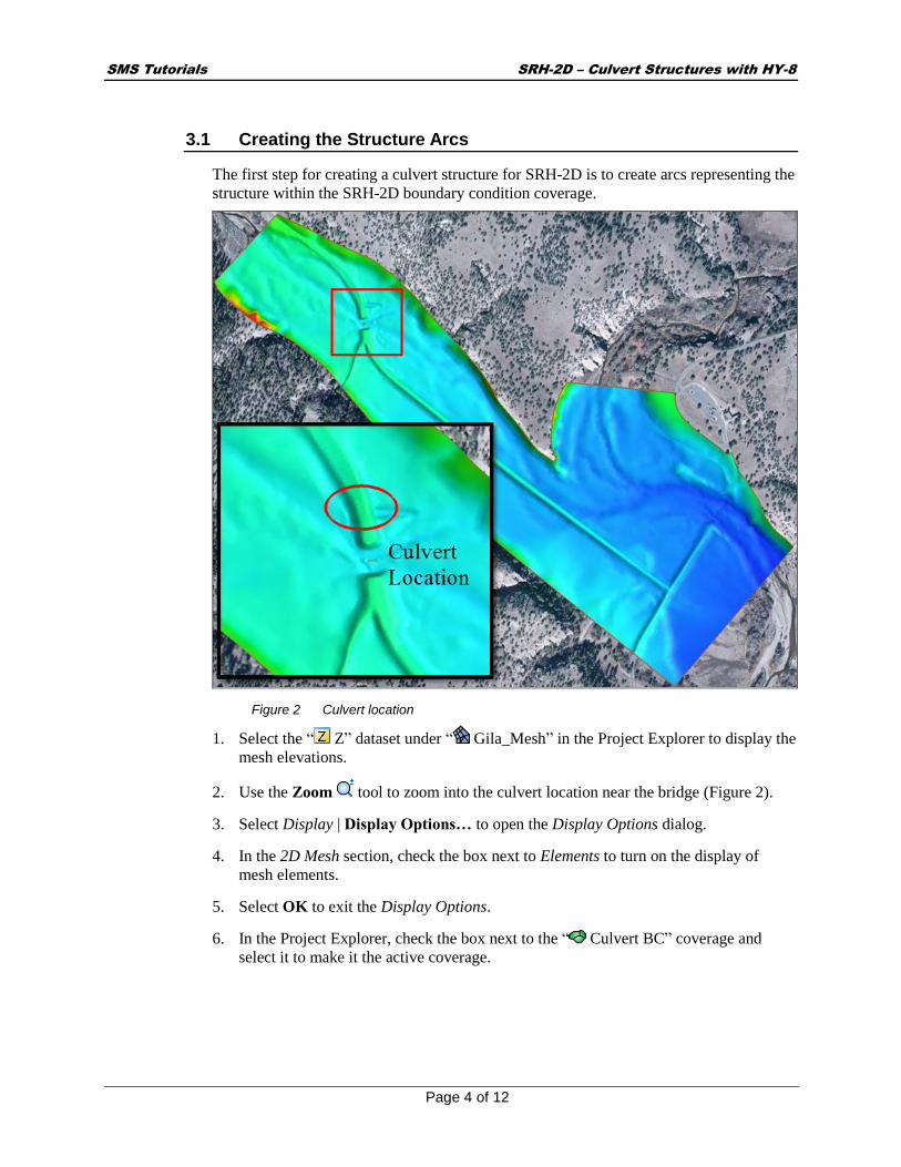
10. Define the culvert and crossing attributes as found in Table 1.
Note: When specifying the Inlet Elevation and Outlet Elevation, care must be taken such
that the specified elevations are not lower than the underlying mesh node elevations. If
the specified inlet and outlet elevations are lower, several approaches could be taken to
remedy the issue such as specifying a higher elevation for the inlet and outlet elevations,
relocating the BC arcs, refining the mesh around the culvert, or editing the mesh node