106
Snap Circuits® Jr. Access Kit Instructions and Labels for Blind or Visually Impaired Project Builders American Printing House for the Blind UEB compliant
Snap Circuits® Jr. Access Kit
Instructions and Labels for Blind or
Visually Impaired Project Builders
American Printing House for the Blind
UEB compliant

Snap Circuits® Jr. Access Kit
©2017 American Printing House for the Blind
Project Staff:
Ken Perry, Programmer III
Heather Kennedy-MacKenzie, Technology Program Manager
Fred Otto, Project Leader
Rachel White, Research Assistant
Frank Hayden, Dir. Technical & Manufacturing Research
Rod Dixon, Manufacturing Specialist
Matt Poppe, Graphic Designer
Thank-you to the following for their thorough evaluations and helpful
suggestions regarding the materials in this kit:
Nancy Arnold, DeBerry Blackwelder, Keith Christian, Monique Coleman, Barbara D. Collins, Sandra Craig, J. Dean Crocker, Joseph Drenth, Tim Fahlberg, Kate Fraser, Lis Geoghegan, Carol Green, Bryan Gueltig, Krystal Guillory, Karen Koehler, Jane Mundschenk, Ann Page, Cecelia Peirano, Mike Plansker, Fay Rahni, Mark Senk, Jamie Sigel, Misty Williams, Nancy Wittmershaus, Leslie Wright, Joanne Zucker
The Snap Circuits® Jr. Access Kit was developed by APH with generous
cooperation and contributions from Elenco®, makers of a wide variety of
learning kits. Please visit www.elenco.com for information about their
products and services. For questions or comments about the Snap
Circuits® Jr. Access Kit, please contact APH.

SNAP CIRCUITS® Jr. ACCESS KIT
Introduction
The Snap Circuits Jr. Breadboard
The Snap Circuits® Jr. breadboard has 7 rows and 10 columns of pegs.
The rows are labeled with slightly embossed characters, from A at the top through G at the bottom (closest to you). The columns are labeled from 1 at the left through 10 at the right. Because the characters lack visual contrast, you may want to make small paper stickers with print lettering to mark the rows and columns, or write directly on the board with a permanent marker.
If you take a few minutes to practice the exercises below, it will prove useful before you begin building projects. Knowing how to place parts in the right locations will ensure that your projects work properly and save you from the frustration that comes when they’re misplaced!
Most of the projects involve separate “layers,” that is, snapping parts on top of other parts. When the pegs you are looking for are already covered up, your skill in finding coordinates with confidence will pay off.
Practice Exercise 1:
Name a coordinate pair (such as f4, a3, or c6) and then point to the peg at that location. Hold your finger on the peg while you double-check your answer. Repeat this numerous times using different coordinates all over the board.

Practice Exercise 2:
Reverse the previous procedure by first pointing to a peg anywhere on the board and then naming its coordinates.
Repeat both exercises with different locations until you are confident and accurate with your answers.
Parts
All parts have braille labels except those which are very distinctive and cannot be confused with other parts, such as the battery pack, speaker, or fan blade. Some parts have an additional label showing the positive terminal or, in the case of the integrated circuit parts (U1, U2, and U3), the location of terminal 1. Some pieces serve only to connect other parts and are referred to by the number of snaps on their top surface, such as “2-snaps” or “5-snaps”.
Each step in the instructions below gives the name of a part followed by the coordinates where it is placed. For example, the instruction “Place S1 switch a5 - c5” means to snap the switch labeled S1 onto the pegs at a5 and c5. When the orientation of a part matters, this is noted in the instructions; otherwise you may assume that there is not a right or wrong direction for placing a part.
A set of braille labels and a key page are provided for marking the storage
tray. Placing these labels on the side walls of the compartments will make
it simpler to store the parts after use, and it may also make locating parts
quicker and easier. You may want to take time to apply these labels to
the tray before your first use of the kit.

Project Instructions
Note: Each set of instructions starts with the battery pack because it is the source of power for each circuit. Since every project includes the battery pack, it may be worthwhile to practice placing it as instructed. The battery pack is square, but it has only two snaps, so it can be tricky to place properly until you are familiar with it. Make sure to place the positive terminal correctly!
Project 1: Electric Light and Switch
This project is a simple circuit with a power source, a light source, and a switch. It is one of the most basic circuits you can learn. It conducts power from the battery to the light and back to the battery through the switch.
Parts needed:
• Battery B1
• Switch S1
• Lamp L1
• Four 2-snaps
• One 3-snap
First layer:
1. Place battery c6 - e6 with positive end at c6. 2. Place S1 switch e3 - e5. 3. Place L1 lamp c3 - c5. 4. Place 3-snap c2 - e2.

Second layer:
5. Place 2-snap c2 - c3. 6. Place 2-snap c5 - c6. 7. Place 2-snap e2 - e3. 8. Place 2-snap e5 - e6.
Turn the slide switch on (toward the label) and the lamp will light up.
Project 2: DC Motor and Switch
Like Project 1, this project is a simple circuit, but instead of the light there is a motor. This converts electrical power into mechanical power. Note the proper orientation of the motor’s positive terminal.
Parts needed:
• Battery B1
• Switch S1
• Motor M1
• Four 2-snaps
• One 3-snap
• Fan blade
First layer: 1. Place battery c6 - e6 with positive end at c6. 2. Place S1 switch e3 - e5. 3. Place M1 motor c3 - c5 with positive end at c5. 4. Place 3-snap c2 - e2.
Second layer: 5. Place 2-snap c2 - c3. 6. Place 2-snap c5 - c6.

7. Place 2-snap e2 - e3. 8. Place 2-snap e5 - e6. 9. Set fan blade on motor shaft.
Turn the slide switch on and the motor will turn the fan blade. WARNING: Do not touch the motor or fan blade while operating. Do not stand or lean directly over the fan while operating.
Project 3: Sound Activated Switch
This is a simple circuit that uses a sound-activated chip to turn on music. The integrated circuit labeled U1 contains a ready-made circuit to create music; without it this project would require you to make a much larger circuit.
Parts needed:
• Battery B1
• Switch S1
• Whistle Chip WC
• Music IC U1
• Speaker
• Two 2-snaps
• One 3-snap
• One 4-snap
• One 5-snap
• Red and black snap wires
First layer:
1. Place battery c5 - e5 with positive end at c5.

2. Place U1 Music IC with 3-snaps at the top, covering c1 - c3 and d1 - d3.
3. Place 5-snap a1 - a5. 4. Place 4-snap e1 - e4.
Second layer:
5. Place WC whistle chip a1 - c1. 6. Place 3-snap a2 - c2. 7. Place S1 switch a5 - c5. 8. Place 2-snap e4 - e5. 9. Place 2-snap d1 - e1. 10. Place speaker a10 - c10. 11. Place black wire a4 - a10. 12. Place red wire d3 - c10.
This circuit plays a tune when you turn the switch on. After it plays the tune the first time it waits for you to make a loud sound over the whistle chip (WC). Once you make a loud sound or vibrate the whistle chip it will play the tune again.
You could connect the speaker with snap connectors rather than wires, but then the speaker may make enough vibration on the board to restart the whistle chip by itself!
Project 4: Adjusting Sound Level
This circuit does the same as Project 3 without the wires. It also adds a resistor to reduce the current flowing to the speaker and lower the sound volume.

Parts needed:
• Battery B1
• Switch S1
• Whistle Chip WC
• Music IC U1
• Resistor R1
• Speaker
• Three 2-snaps
• One 3-snap
• One 5-snap
• One 6-snap
First layer:
1. Place 6-snap a1 - a6. 2. Place 5-snap e1 - e5. 3. Place U1 music IC 3-snaps at top, covering c1 - c3 and d1 - d3. 4. Place speaker b5 - d5. 5. Place battery c6 - e6 with positive end at c6.
Second layer:
6. Place WC whistle chip a1 - c1. 7. Place 3-snap a2 - c2. 8. Place 2-snap d1 - e1. 9. Place r1 resistor d3 - d5. 10. Place 2-snap a5 - b5. 11. Place s1 switch a6 - c6. 12. Place 2-snap e5 - e6.

As in Project 3, turning the slide switch on makes the music play and then stop. Making a sharp sound or tapping the whistle chip starts the music again.
Project 5: Lamp and Fan in Series
This simple circuit shows how a lamp can indicate when a fan is running and shows how two components in a series can “compete” with each other.
Parts needed:
• Battery B1
• Switch S1
• Lamp L1
• Motor M1
• Four 2-snaps
• Fan blade
First layer:
1. Place L1 lamp b2 - b4. 2. Place M1 motor c2 - e2 with positive end at c2. 3. Place battery d4 - f4 with positive end at d4. 4. Place 2-snap f2 - f3.
Second layer:
5. Place 2-snap b2 - c2. 6. Place 2-snap e2 - f2. 7. Place S1 switch b4 - d4. 8. Place 2-snap f3 - f4. 9. Place fan blade on motor shaft.

When you turn the switch on, the lamp will light and the fan will spin. Part of the voltage goes to the lamp and part goes to the motor. If you remove the fan blade the motor will run faster because it has less work to do; as a result the lamp gets dimmer. WARNING: Do not touch the motor or fan blade while operating. Do not stand or lean directly over the fan while operating.
Project 6: Lamp and Fan in Parallel
Similar to Project 5, but in this circuit the lamp and the motor do not affect one another.
Parts needed:
• Battery B1
• Switch S1
• Lamp L1
• Motor M1
• Fan blade
• Five 2-snaps
• One 3-snap
• One 4-snap
First layer:
1. Place 4-snap b2 - b5. 2. Place M1 motor c2 - e2 with positive end at c2. 3. Place L1 lamp c3 - e3. 4. Place 3-snap f2 - f4. 5. Place battery d5 - f5 with positive end at d5.

Second layer:
6. Place 2-snap b2 - c2. 7. Place 2-snap b3 - c3. 8. Place S1 switch b5 - d5. 9. Place 2-snap e2 - f2. 10. Place 2-snap e3 - f3. 11. Place 2-snap f4 - f5. 12. Place fan blade on motor shaft.
Turn on the switch and both the lamp and fan will turn on. Notice, however, that removing the fan blade in this circuit has no effect on the lamp’s brightness, as the lamp has its own path to the battery. WARNING: Do not touch the motor or fan blade while operating. Do not stand or lean directly over the fan while operating.
Project 7: Light Emitting Diode (LED)
This simple circuit with a switch and a resistor causes the LED to light. Build Projects 7 and 8 in succession to demonstrate the key feature of a diode.
Parts needed:
• Battery B1
• Switch S1
• Resistor R1
• Light Emitting Diode D1
• Four 2-snaps
First layer:
1. Place resistor R1 c3 - e3.

2. Place battery c5 - e5 with positive end at c5. 3. Place switch S1 b3 - b5. 4. Place diode D1 f3 - f5 with positive end at f3.
Second layer:
5. Place 2-snap b3 - c3. 6. Place 2-snap b5 - c5. 7. Place 2-snap e3 - f3. 8. Place 2-snap e5 - f5.
Turn on the switch and the LED comes on. NOTE: The resistor is needed in this circuit because it limits the current and prevents possible damage to the LED.
Project 8: One Direction for LED
Change the positive end of the diode in Project 7 to f5 and the negative end to f3. Note that the LED does not light up because a diode acts like a valve, only letting current flow in one direction.
Project 9: Conduction Detector
Remove the switch from Project 7, leaving the two 2-snaps in place. Unbend a metal paper clip and place it across the terminals at b3 and b5. The LED will light up because the metal is a good conductor of current. Try using your finger instead of the paper clip, and then test other materials such as plastic or wood to see which ones conduct well and which ones don’t.

Project 10: Space War Alarm Combo
This circuit combines the sounds from the Space War IC and the Alarm IC and offers ways to play them in different combinations.
Parts needed:
• Battery B1
• Lamp L1
• Speaker
• Alarm IC U2
• Space War IC U3
• Switch S1
• Switch S2
• Photoresistor RP
• Black and red snap wires
• Three 1-snaps
• Six 2-snaps
• Two 3-snaps
• One 4-snap
• One 5-snap
First layer:
1. Place U2 Alarm IC with 3-snaps at the top, covering a2 - a4 and b2 - b4.
2. Place U3 Space War IC with 2-snaps at top, covering c2 - c4 and d2 - d4.
3. Place speaker a5 - c5. 4. Place L1 lamp a6 - c6. 5. Place battery a7 - c7 with positive end at a7. 6. Place 5-snap f1 - f5.
7. Place 1-snap f7.
Second layer:
8. Place 2-snap a2 - a3. 9. Place 2-snap a5 - a6. 10. Place 1-snap a7. 11. Place 2-snap b4 - c4. 12. Place 2-snap c5 - c6. 13. Place S2 switch d2 - f2. 14. Place 3-snap d3 - f3. 15. Place RP photoresistor d4 - f4. 16. Place 1-snap f5. 17. Place 4-snap c7 - f7.
Third layer:
18. Place 3-snap a3 - a5. 19. Place 2-snap a6 - a7. 20. Place 2-snap c4 - c5. 21. Place S1 switch f5 - f7. 22. Connect black wire a2 - c2. 23. Connect red wire b2 - f1.
Turn on slide switch S1, then press switch S2 repeatedly and wave your hand over the photoresistor RP to hear different sound combinations. If the sound is too loud, try replacing the speaker with whistle chip WC.
Project 11: Flying Saucer
This launches the spinning fan blade on the motor when the switch is turned off. Note that it is the same as Project 2 except that the polarity of the motor is reversed.
Parts needed:
• Battery B1
• Switch S1
• Motor M1
• Fan blade
• Four 2-snaps
• One 3-snap
First layer:
1. Place battery c6 - e6 with positive end at c6. 2. Place S1 switch e3 - e5. 3. Place M1 motor c3 - c5 with positive end at c3. 4. Place 3-snap c2 - e2.
Second layer:
5. Place 2-snap c2 - c3. 6. Place 2-snap c5 - c6. 7. Place 2-snap e2 - e3. 8. Place 2-snap e5 - e6. 9. Set fan blade on motor shaft.
Turn the slide switch on and the motor will turn the fan blade. When the motor has reached maximum speed, turn the switch off. The fan blade should rise and float in the air like a flying saucer. WARNING: Do not touch the motor or fan blade while operating. Do not stand or lean directly over the fan while operating.

Project 12: Decreasing Saucer Lift
This shows how adding resistance to the previous circuit affects the speed of the motor and affects the lift of the fan blade.
New part needed:
• Lamp L1
Change the circuit in Project 11 by replacing the 3-snap at c2 - e2 with L1 lamp. When you turn the switch on, the lamp reduces the current through the motor because they are in series, and this reduces the top speed of the motor. Turn the switch off and observe the difference in the lift of the fan blade, if it even launches at all. WARNING: Do not touch the motor or fan blade while operating. Do not stand or lean directly over the fan while operating.
Project 13: Two-Speed Fan
This circuit shows how to use switches to increase or decrease the speed of the fan.
Parts needed:
• Switch S1
• Switch S2
• Lamp L1
• Battery B1
• Motor M1
• Fan blade
• Two 1-snaps
• Six 2-snaps
First layer:
1. Place M1 motor b3 - b5. 2. Place S2 switch c3 - e3. 3. Place L1 lamp c4 - e4. 4. Place battery d5 - f5 with positive end at d5. 5. Place 2-snap f3 - f4.
Second layer:
6. Place 2-snap b3 - c3. 7. Place 1-snap c4. 8. Place S1 switch b5 - d5. 9. Place 1-snap e4. 10. Place 2-snap e3 - f3. 11. Place 2-snap f4 - f5.
Third layer:
12. Place 2-snap c3 - c4. 13. Place 2-snap e3 - e4. 14. Place fan blade on motor shaft.
When you turn on switch S1, current flows from the battery through S1, the motor, the lamp, and back to the battery. When you press switch S2, the lamp is shorted and the speed of the motor increases. WARNING: Do not touch the motor or fan blade while operating. Do not stand or lean directly over the fan while operating.
Project 14: The Fuse
Use the circuit built in Project 13. With the fan running, remove the 2-snap at f4 - f5. This simulates a fuse and opens the circuit. Nothing will work until you replace the snap. WARNING: Do not touch the motor or

fan blade while operating. Do not stand or lean directly over the fan while operating.
Project 15: Musical Doorbell
This circuit uses the Music IC and the press switch to simulate a doorbell.
Parts needed:
• Battery B1
• Switch S1
• Switch S2
• LED D1
• Music IC U1
• Resistor R1
• Speaker
• Two 1-snaps
• Five 2-snaps
• One 3-snap
• One 5-snap
• One 6-snap
First layer:
1. Place 6-snap a2 - a7. 2. Place D1 LED c1 - e1. 3. Place U1 Music IC with three snaps at top, covering c2 - c4 and d2 -
d4. 4. Place speaker b6 - d6. 5. Place battery c7 - e7 with positive end at c7. 6. Place 5-snap e2 - e6.

Second layer:
7. Place S2 switch a2 - c2. 8. Place 3-snap a3 - c3. 9. Place R1 resistor d4 - d6. 10. Place 2-snap a6 - b6. 11. Place S1 switch a7 – c7. 12. Place 1-snap c1. 13. Place 1-snap e1. 14. Place 2-snap d2 - e2. 15. Place 2-snap e6 - e7.
Third layer:
16. Place 2-snap c1 - c2. 17. Place 2-snap e1 - e2.
When you turn on switch S1, the Music IC should play its tune and then stop. Each time you press switch S2, the complete tune will play even after you release the switch.
Project 16: Momentary Alarm
This project modifies the one in Project 15 so that the music is louder and it only plays while the press switch is held down.
Parts needed:
• Battery B1
• Switch S1
• Switch S2
• Music IC U1
• Speaker
• Four 2-snaps
• One 3-snap
• One 4-snap
• One 5-snap
First layer:
1. Place 5-snap a1 - a5. 2. Place U1 Music IC with three snaps at top, covering c1 - c3 and d1 -
d3. 3. Place speaker b4 - d4. 4. Place battery c5 - e5 with positive end at c5. 5. Place 4-snap e1 - e4.
Second layer:
6. Place 3-snap a2 - c2. 7. Place S2 switch a3 - c3. 8. Place 2-snap a4 - b4. 9. Place S1 switch a5 - c5. 10. Place 2-snap d1 - e1. 11. Place 2-snap d3 - d4. 12. Place 2-snap e4 - e5.
When you turn on switch S1, the tune will play through and then stop. It will be louder than in the previous project because there is less resistance in the circuit. Each time you press S2 the music will play again, but only while you hold down the button.
Project 17: Alarm Circuit
This project is similar to Project 16 but uses a different IC to make loud alarm sounds.

Parts needed:
• Battery B1
• Switch S1
• Alarm IC U2
• Speaker
• Four 2-snaps
• One 3-snap
• One 4-snap
• One 5-snap
First layer:
1. Place 5-snap a1 - a5. 2. Place U2 Alarm IC with three snaps at top, covering c1 - c3 and d1 -
d3. 3. Place speaker b4 - d4. 4. Place battery c5 - e5 with positive end at c5. 5. Place 4-snap e1 - e4.
Second layer:
6. Place 3-snap a2 - c2. 7. Place 2-snap a4 - b4. 8. Place S1 switch a5 - c5. 9. Place 2-snap d1 - e1. 10. Place 2-snap d3 - d4. 11. Place 2-snap e4 - e5.
Turn the slide switch on and a loud alarm will sound.

Project 18: Laser Gun
This project modifies the previous one to make the Alarm IC produce laser gun sounds.
Parts needed:
• Battery B1
• Switch S1
• Alarm IC U2
• Speaker
• Resistor R1
• Three 2-snaps
• Two 3-snaps
• One 5-snap
• One 6-snap
First layer:
1. Place 6-snap a1 - a6. 2. Place U2 Alarm IC with three snaps at top, covering c1 - c3 and d1 -
d3. 3. Place speaker b5 - d5. 4. Place battery c6 - e6 with positive end at c6. 5. Place 5-snap e1 – e5.
Second layer:
6. Place 3-snap a2 - c2. 7. Place 3-snap a3 - c3. 8. Place 2-snap a5 - b5. 9. Place S1 switch a6 - c6. 10. Place R1 resistor d3 - d5.

11. Place 2-snap d1 - e1. 12. Place 2-snap e5 - e6.
When you turn on the switch the IC will play laser gun sounds. Try switching the circuit on and off quickly to achieve different sound effects.
Project 19: Space War
This project introduces the variety of sounds the Space War IC can make.
Parts needed:
• Battery B1
• Switch S1
• Switch S2
• Space War IC U3
• Speaker
• One 2-snap
• Three 3-snaps
• One 4-snap
• One 5-snap
First layer:
1. Place 5-snap a1 - a5. 2. Place U3 Space War IC with two snaps at top, covering c1 - c3 and d1
- d3. 3. Place battery c4 - e4 with positive end at c4. 4. Place 4-snap f1 - f4.
Second layer:
5. Place 3-snap a1 - c1.

6. Place speaker a3 - c3. 7. Place 3-snap a4 - c4. 8. Place S2 switch d1 - f1. 9. Place 3-snap d2 - f2. 10. Place S1 switch d3 - f3. 11. Place 2-snap e4 - f4.
Activate this circuit by flipping the slide switch or pressing the press switch. Do both several times and in combination to hear a range of space war sounds.
Project 20: “Light Switch”
This project shows that light can be used to control a circuit with a photoresistor acting as a “switch.”
Use the circuit built in Project 19, but replace slide switch S1 with the photoresistor RP at d3 - f3. The circuit immediately makes sounds. Try turning it off—you’ll discover that the only way is to cover the photoresistor or to make the room very dark.
Project 21: Paper Space War
This project gives a more dramatic demonstration of using the photoresistor.
Use the same circuit as for Project 20. Find a piece of white paper that has a lot of large black or dark areas on it and slowly slide it over the photosensitive resistor. You should hear the sound pattern constantly changing as the white and dark areas of the paper control the light to the

photosensitive resistance. You can also try the pattern printed in the original instruction manual or something similar to it.
Project 22: Light Police Siren
This project shows you how to build a police siren that is controlled by light.
Parts needed:
• Battery B1
• Switch S1
• Alarm IC U2
• Music IC U1
• Speaker
• Photoresistor RP
• One 1-snap
• Four 2-snaps
• Two 3-snaps
• One 4-snap
• One 5-snap
• One 6-snap
First layer:
1. Place battery e6 - e8 with positive end e8. 2. Place U2 Alarm IC with three snaps at the top, covering c4 - c6 and
d4 - d6. 3. Place U1 Music IC with three snaps at the top, covering c1 - c3 and
d1 - d3. 4. Place 6-snap a1 - a6. 5. Place 4-snap a8 - d8.

6. Place 5-snap e1 - e5.
Second layer:
7. Place speaker d6 - d8. 8. Place S1 switch a6 - a8. 9. Place RP photoresistor a3 - c3. 10. Place 3-snap a2 - c2. 11. Place 3-snap a5 - c5. 12. Place 2-snap d1 - e1. 13. Place 2-snap d3 - d4. 14. Place 2-snap e5 - e6. 15. Place 1-snap e8.
Third layer:
16. Place 2-snap d8 - e8.
Cover the photoresistor RP and turn switch S1 on. A police siren with music is heard for a while and stops; then you can control the siren by covering or uncovering the photoresistor.
Project 23: More Loud Sounds
This project shows you variations of the circuit in Project 22.
Modify Project 22 by connecting coordinates a6 and c6. The circuit works the same way, but now it sounds like a machine gun with music.
Project 24: More Loud Sounds (II)
This project shows variations of the circuit in Project 22.
Now remove the connection between a6 and c6 and then make a connection between a4 and c4. The circuit works the same way, but now it sounds like a fire engine with music.
Project 25: More Loud Sounds (III)
This project shows variations of the circuit in Project 22.
Remove the connection between a4 and c4 and then make a connection between c4 and d4. The circuit works the same way, but now it sounds like an ambulance with music.
Project 26: More Loud Sounds (IV)
This project shows variations of the circuit in Project 22.
Now remove the connections between c4 and d4 and between a5 and c5 and then make a connection between a4 and c4. The circuit works the same way, but now it sounds like a familiar song but with static.
Project 27: Clap Sounds
Build a police siren and other sounds that are controlled by clapping your hands.
Parts needed:
• Battery B1
• Switch S1
• Speaker
• Alarm IC U2

• Music IC U1
• Resistor R1
• Whistle Chip WC
• Six 2-snaps
• Three 3-snaps
• One 4-snap
• One 5-snap
• One 6-snap
First layer:
1. Place battery e7 - e9 with positive end e9. 2. Place S1 switch b9 - d9. 3. Place speaker b8 - d8. 4. Place U2 Alarm IC with three snaps at the top, covering c4 - c6 and
d4 - d6. 5. Place U1 Music IC with three snaps at the top, covering c1 - c3 and
d1 - d3. 6. Place 6-snap a1 - a6. 7. Place 4-snap a7 - a10. 8. Place 5-snap e1 - e5.
Second layer:
9. Place R1 resistor d6 - d8. 10. Place WC whistle chip a1 - c1. 11. Place 3-snap a2 - c2. 12. Place 3-snap a5 - c5. 13. Place 2-snap a6 - a7. 14. Place 2-snap a8 - b8. 15. Place 2-snap a9 - b9. 16. Place 2-snap d1 - e1. 17. Place 2-snap d3 - d4.

18. Place 2-snap d9 - e9. 19. Place 3-snap e5 - e7.
Turn switch S1 on (toward the label), and a police siren is heard and then stops. Clap your hands, and it will play again. Note, however, that music can be heard faintly in the background of the siren. If clapping does not trigger the sound, tap the whistle chip WC with your finger.
Project 28: More Clap Sounds
This project will show how ICs can do many jobs.
Modify the last circuit by connecting coordinates a6 and c6. The circuit works the same way, but now it sounds like a machine gun.
Project 29: More Clap Sounds (II)
This project will show how ICs can do many jobs.
Remove the connection between a6 and c6 and then make a connection between a4 and c4. The circuit works the same way, but now it sounds like a fire engine.
Project 30: More Clap Sounds (III)
This project will show how ICs can do many jobs.
Now remove the connection between a4 and c4 and then make a connection between c4 and d4. The circuit works the same way, but now it sounds like an ambulance.

Project 31: More Clap Sounds (IV)
This project will show how ICs can do many jobs.
Remove the connections between c4 and d4 and between a5 and c5 and then make a connection between a4 and c4. The circuit works the same way, but now it sounds like a familiar song but with static.
Project 32: Voice Light Diode
In this project, you will build a circuit that uses your voice to control a light emitting diode.
Parts needed:
• Battery B1
• Switch S1
• Space War IC U3
• Music IC U1
• LED D1
• Whistle Chip WC
• Two 1-snaps
• Four 2-snaps
• Three 3-snaps
• One 5-snap
• One 6-snap
First layer:
1. Place battery c7 - e7 with positive end c7. 2. Place U3 Space War IC with two snaps at the top, covering c4 - c6
and d4 - d6.
3. Place U1 Music IC with three snaps at the top, covering c1 - c3 and d1 - d3.
4. Place 6-snap a1 - a6. 5. Place 1-snap a7. 6. Place 5-snap e1 - e5.
Second Layer:
7. Place S1 switch e5 - e7. 8. Place D1 LED a6 - c6 with positive end a6. 9. Place WC whistle chip a1 - c1. 10. Place 3-snap a2 - c2. 11. Place 3-snap a4 - c4. 12. Place 3-snap a7 - c7. 13. Place 2-snap d1 - e1. 14. Place 2-snap d3 - d4. 15. Place 1-snap d5.
Third layer:
16. Place 2-snap a6 - a7. 17. Place 2-snap d5 - e5.
Build the circuit and turn switch S1 on (toward the label). The LED may be on for a while and then turn off. Clap or talk loud, and the LED will light again and keep flickering for a little while.
Project 33: Voice Control
In this project, you will use your voice to control sounds.

The preceding circuit probably did not seem too exciting, so replace the LED D1 with the speaker. You hear a range of exciting sounds. Clap or talk loudly, and the sounds will resume.
If you find that the sound does not turn off, then vibrations created by the speaker may be activating the whistle chip WC. Set the speaker on the table near the circuit and connect it to the same locations using the jumper wires to prevent this.
Project 34: Motor Space Sounds
In this project, you will build a circuit that uses a motor to activate space war sounds.
Parts needed:
• Battery B1
• Switch S1
• Space War IC U3
• Music IC U1
• Speaker
• Motor M1
• Two 1-snaps
• Four 2-snaps
• Three 3-snaps
• One 5-snap
• One 6-snap
First layer:
1. Place battery c7 - e7 with positive end c7.

2. Place U3 Space War IC with two snaps at the top, covering c4 - c6 and d4 - d6.
3. Place U1 Music IC with three snaps at the top, covering c1 - c3 and d1 - d3.
4. Place 6-snap a1 - a6. 5. Place 1-snap a7. 6. Place 5-snap e1 - e5.
Second layer:
7. Place S1 switch e5 - e7. 8. Place speaker a6 - c6. 9. Place M1 motor a1 - c1 with positive end a1. 10. Place 3-snap a2 - c2. 11. Place 3-snap a4 - c4. 12. Place 3-snap a7 - c7. 13. Place 2-snap d1 - e1. 14. Place 2-snap d3 - d4. 15. Place 1-snap d5.
Third layer:
16. Place 2-snap a6 - a7. 17. Place 2-snap d5 - e5.
Turn it on and wait for any sounds to stop; then spin the motor and the sounds play again.
Do you know why turning the motor makes the sounds play? Actually, the DC motor is also a DC generator, and when you turn it, the motor generates a voltage that triggers the sound circuits.

Project 35: Motor Space Light
Build a circuit that uses a motor to activate a light diode.
This circuit is loud and may bother other people around you, so replace the speaker with the LED (position it like in Project 32); the circuit operates in the same manner.
Project 36: Space Battle (II)
This project shows another way of using the space war integrated circuit.
Parts needed:
• Battery B1
• Switch S1
• Space War IC U3
• Alarm IC U2
• Speaker
• Motor M1
• Two 1-snaps
• Four 2-snaps
• Three 3-snaps
• One 5-snap
• One 6-snap
First layer:
1. Place battery c7 - e7 with positive end c7. 2. Place U3 Space War IC with two snaps at the top, covering c4 - c6
and d4 - d6.

3. Place Alarm IC U2 with three snaps at the top, covering c1 - c3 and d1 - d3.
4. Place 6-snap a1 - a6. 5. Place 1-snap a7. 6. Place 5-snap e1 - e5.
Second layer:
7. Place S1 switch e5 - e7. 8. Place speaker a6 - c6. 9. Place M1 motor a2 - c2. 10. Place 3-snap a3 - c3. 11. Place 3-snap a4 - c4. 12. Place 3-snap a7 - c7. 13. Place 2-snap d1 - e1. 14. Place 2-snap d3 - d4. 15. Place 1-snap d5.
Third layer:
16. Place 2-snap a6 - a7. 17. Place 2-snap d5 - e5.
This circuit is based on the Space War in Project 19. Turn on the switch and you will hear exciting sounds, as if a space battle is raging!
The motor is used here as a connecting wire and will not spin.
Project 37: Silent Space Battle
This project shows another way of using the Space War part.

The preceding circuit is loud and may bother people around you, so replace the speaker with LED D1 and position it with positive end at a6. Now you have a silent space battle.
Project 38: Periodic Sounds
Build a circuit with light and sound that change and repeat.
Parts needed:
• Battery B1
• Switch S1
• Music IC U1
• Alarm IC U2
• Speaker
• Lamp L1
• Three 1-snaps
• Six 2-snaps
• One 4-snap
• One 5-snap
• One 6-snap
First layer:
1. Place battery c6 - e6 with positive end c6. 2. Place U1 Music IC with three snaps at the left, covering c4 - c5 and
e4 - e5. 3. Place U2 Alarm IC with three snaps at the top, covering b1 - b3 and
c1 - c3. 4. Place 5-snap a2 - a6. 5. Place 6-snap f1 - f6.

Second layer:
6. Place S1 switch a6 - c6. 7. Place speaker a5 - c5. 8. Place L1 lamp a4 - c4. 9. Place 4-snap c1 - f1. 10. Place 2-snap a2 - b2. 11. Place 2-snap a3 - b3. 12. Place 1-snap c3. 13. Place 1-snap d4. 14. Place 2-snap e5 - f5. 15. Place 2-snap e6 - f6.
Third layer:
16. Place 1-snap c3. 17. Place 2-snap c4 - d4.
Fourth layer:
18. Place 2-snap c3 - c4.
Build the circuit and turn it on. The lamp L1 alternates between being on and off, while the speaker alternates between two musical tones--like someone is flipping a switch but at a very consistent rate. Periodic signals like this are very important in electronics.
Project 39: Blinking Double Flashlight
Build a circuit with two lights that alternate.
In the previous circuit, replace the speaker with LED D1; position it as in Project 32. The lamp alternates between being on and off while the LED alternates between being dimmer and brighter.

Project 40: Motor-Controlled Sounds
This project will show how motion can trigger electronic circuits.
Parts needed:
• Battery B1
• Switch S1
• Speaker
• Alarm IC U2
• Music IC U1
• Resistor R1
• Motor M1
• Six 2-snaps
• Three 3-snaps
• One 4-snap
• One 5-snap
• One 6-snap
First layer:
1. Place battery e7 - e9 with positive end e9. 2. Place S1 switch b9 - d9. 3. Place speaker b8 - d8. 4. Place U2 Alarm IC with three snaps at the top, covering c4 - c6 and
d4 - d6. 5. Place U1 Music IC with three snaps at the top, covering c1 - c3 and
d1 - d3. 6. Place 6-snap a1 - a6. 7. Place 4-snap a7 - a10. 8. Place 5-snap e1 - e5.

Second layer:
9. Place R1 resistor d6 - d8. 10. Place M1 motor a1 - c1 with positive end a1. 11. Place 3-snap a2 - c2. 12. Place 3-snap a5 - c5. 13. Place 2-snap a6 - a7. 14. Place 2-snap a8 - b8. 15. Place 2-snap a9 - b9. 16. Place 2-snap d1 - e1. 17. Place 2-snap d3 - d4. 18. Place 2-snap d9 - e9. 19. Place 3-snap e5 - e7.
This circuit is controlled by spinning the motor with your hands. Turn switch S1 on (toward the label). A police siren is heard and then stops. Spin the motor, and it will play again. Note, however, that music can be heard faintly in the background of the siren.
Project 41: More Motor Sounds
This project will show how motion can trigger electronic circuits.
Modify the last circuit by connecting coordinates a6 and c6 with the lamp L1. The circuit works the same way, but now it sounds like a machine gun.
Project 42: More Motor Sounds (II)
This project will show how motion can trigger electronic circuits.

Now remove the connection between a6 and c6 and make a connection between a4 and c4 with the lamp L1. The circuit works the same way, but now it sounds like a fire engine.
Project 43: More Motor Sounds (III)
This project will show how motion can trigger electronic circuits.
Remove the connection between a4 and c4, and make a connection between c4 and d4 using a jumper wire. The circuit works the same way, but now it sounds like an ambulance.
Project 44: More Motor Sounds (IV)
This project will show how motion can trigger electronic circuits.
Remove the wire between c4 and d4. Now move the 3-snap from a5 - c5 to a4 - c4. The circuit works the same way, but now it sounds like a familiar song but with static.
Project 45: Light-Controlled Flicker
Make a circuit that uses light to control the blinking of another light.
Parts needed:
• Battery B1
• Switch S1
• Alarm IC U2
• Music IC U1
• LED D1

• Photoresistor RP
• Two 1-snaps
• Four 2-snaps
• Three 3-snaps
• One 4-snap
• One 5-snap
• One 6-snap
First layer:
1. Place battery e6 - e8 with positive end e8. 2. Place U2 Alarm IC with three snaps at the top, covering c4 - c6 and
d4 - d6. 3. Place U1 Music IC with three snaps at the top, covering c1 - c3 and
d1 - d3. 4. Place 6-snap a1 - a6. 5. Place 4-snap a8 - d8. 6. Place 5-snap e1 - e5.
Second layer:
7. Place D1 LED d6 - d8 with positive end d8. 8. Place S1 switch a6 - a8. 9. Place RP photoresistor a3 - c3. 10. Place 3-snap a2 - c2. 11. Place 3-snap a5 - c5. 12. Place 1-snap c6. 13. Place 2-snap d1 - e1. 14. Place 2-snap d3 - d4. 15. Place 2-snap e5 - e6. 16. Place 1-snap e8.

Third layer:
17. Place 3-snap a6 - c6. 18. Place 2-snap d8 - e8.
This circuit does not use the noisy speaker but uses a nice quiet LED. Turn on switch S1, and the LED flickers. Wait a few seconds, then cover the photoresistor RP, and the flicker stops. The flicker is controlled by the photoresistor; uncover it, and the flicker resumes.
People who are deaf need lights to tell them when a doorbell is ringing. They also use circuits like this to tell them if an alarm has been triggered or an oven is ready. Can you think of other uses?
Project 46: More Sound Effects
Investigate the different sound effects available from the alarm integrated circuit.
Parts needed:
• Battery B1
• Switch S1
• Resistor R1
• Speaker
• Alarm IC U2
• Three 2-snaps
• Two 3-snaps
• One 5-snap
• One 6-snap

First layer:
1. Place battery c6 - e6 with positive end c6. 2. Place speaker b5 - d5. 3. Place U2 Alarm IC with three snaps at the top, covering c1 - c3 and
d1 - d3. 4. Place 6-snap a1 - a6. 5. Place 5-snap e1 - e5.
Second layer:
6. Place S1 switch a6 - c6. 7. Place R1 resistor d3 - d5. 8. Place 3-snap a1 - c1. 9. Place 3-snap a2 - c2. 10. Place 2-snap a5 - b5. 11. Place 2-snap d1 - e1. 12. Place 2-snap e5 - e6.
When you close switch S1, the Alarm IC should start sounding an up-down siren. This is just one more sound effect that this integrated circuit is designed to produce. Different sounds that can easily be changed are very important when designing games and toys. Switch the sound on and off quickly and see if you can create even different effects. This mode will create many robotic sounds if switched quickly.
Project 47: This OR That
This project will introduce you to the OR concept of electronic wiring.
Parts needed:
• Battery B1
• Switch S1

• Switch S2
• LED D1
• Resistor R1
• Two 1-snaps
• Six 2-snaps
First layer:
1. Place battery a5 - c5 with positive end a5. 2. Place D1 LED c2 - c4 with positive end c2. 3. Place S2 switch b2 - b4. 4. Place S1 switch a2 - a4. 5. Place R1 resistor a1 - c1.
Second layer:
6. Place 2-snap a1 - a2. 7. Place 2-snap a4 - a5. 8. Place 1-snap b2. 9. Place 1-snap b4. 10. Place 2-snap c1 - c2. 11. Place 2-snap c4 - c5.
Third layer:
12. Place 2-snap a2 - b2. 13. Place 2-snap a4 - b4.
Notice that if you turn on switch S1 OR press switch S2 the LED lights up. There is no partially lit state here; the diode is either totally on or totally off. While this may seem very simple and boring, it represents an important concept in electronics. Two switches like this may be used to turn on a light in your house, or they might be two sensors at a railroad crossing used to start the ding-ding sound and lower the gate. You could

also have more than two switches, and the circuit would function the same way.
Project 48: This AND That
This project introduces you to digital circuits.
Parts needed:
• Battery B1
• Switch S1
• Resistor R1
• Switch S2
• LED D1
• One 3-snap
First layer:
1. Place battery a5 - c5 with positive end a5. 2. Place S1 switch c1 - c3. 3. Place R1 resistor a1 - a3.
Second layer:
4. Place S2 switch c3 - c5. 5. Place D1 LED a1 - c1 with positive end a1. 6. Place 3-snap a3 - a5.
Notice that if you turn on switch S1 AND press switch S2, the LED lights up. Once again, there is no partially lit state here; the LED is either totally on or totally off. Two switches like this may be used to turn on the same light in your house, the room switch and the master switch in the
electrical box. You could also have more than two switches, and the circuit would function the same way.
Combinations of AND and OR circuits are used to add and multiply numbers together in modern computers. These circuits are made of tiny transistors in massive integrated circuits.
Project 49: Neither This NOR That
This project will demonstrate the concept of a NOR circuit.
Parts needed:
• Battery B1
• Switch S1
• Switch S2
• LED D1
• Resistor R1
• Four 2-snaps
• One 3-snap
First layer:
1. Place battery a5 - c5 with positive end a5. 2. Place D1 LED a3 - c3 with positive end a3. 3. Place S2 switch a2 - c2. 4. Place S1 switch a1 - c1.
Second layer:
5. Place R1 resistor a3 - a5. 6. Place 2-snap a1 - a2. 7. Place 2-snap c1 - c2.
8. Place 3-snap c3 - c5.
Third layer:
9. Place 2-snap a2 - a3. 10. Place 2-snap c2 - c3.
Build the circuit and test the combinations of switch S1 and switch S2. If you compare it to the OR circuit in Project 47, you can see the LED lights in the opposite combinations of that circuit. Hence, we refer to it as a NOR circuit (short for “NOT this OR that”). Like the OR and AND, it is an important building block in computers.
Project 50: NOT This AND That
This project will demonstrate the concept of a NAND circuit.
Parts needed:
• Battery B1
• Switch S1
• Switch S2
• LED D1
• Resistor R1
• Two 1-snaps
• Two 3-snaps
First layer:
1. Place battery a5 - c5 with positive end a5. 2. Place D1 LED a3 - c3 with positive end a3. 3. Place S1 switch a1 - c1.

Second layer:
4. Place R1 resistor a3 - a5. 5. Place 1-snap a1. 6. Place 1-snap c1. 7. Place 3-snap c3 - c5.
Third layer:
8. Place S2 switch a1 - a3. 9. Place 3-snap c1 - c3.
Test the combinations of S1 and S2. If you compare this to the AND circuit in Project 48, you can see the LED lights in the opposite combinations of that circuit. Hence, we refer to it as a NAND circuit (short for “NOT this AND that”). This circuit can also have more or less than two inputs, though when it only has one input it is referred to as a NOT circuit. Like the OR, AND, and NOR, NAND and NOT are important building blocks in computers.
Project 51: Reflection Detector
This project will allow you to detect if a mirror is present.
Parts needed:
• Battery B1
• Switch S1
• Space War IC U3
• Lamp L1
• Photoresistor RP
• Speaker
• Two 2-snaps

• Three 3-snaps
• One 4-snap
• One 5-snap
• A hand mirror
First layer:
1. Place battery c5 - e5 with positive end c5. 2. Place U3 Space War IC with two snaps at the top, covering c1 - c3
and d1 - d3. 3. Place 5-snap a1 - a5. 4. Place 3-snap b4 - d4. 5. Place 4-snap f2 - f5.
Second layer:
6. Place S1 switch a5 - c5. 7. Place L1 lamp d4 - f4. 8. Place RP photoresistor d3 - f3. 9. Place speaker a3 - c3. 10. Place 3-snap a1 - c1. 11. Place 2-snap a4 - b4. 12. Place 3-snap d2 - f2. 13. Place 2-snap e5 - f5.
Place the circuit where there won’t be any room light hitting the photoresistor RP (such as in a dark room or under a table) and then turn it on. The 2.5V lamp L1 will be bright, but there should be no sound.
Take a small mirror and hold it over the lamp and photoresistor. You should hear sound now. You have a reflection detector! You can also use a white piece of paper instead of a mirror, since white surfaces reflect light.

Project 52: Quieter Reflection Detector
This project will show you how to detect a mirror.
Parts needed:
• Battery B1
• Switch S1
• LED D1
• Whistle Chip WC
• Music IC U1
• Resistor R1
• Lamp L1
• Photoresistor RP
• Three 1-snaps
• Six 2-snaps
• Three 3-snaps
• One 4-snap
• One 5-snap
• One 6-snap
First layer:
1. Place battery b8 - d8 with positive end b8. 2. Place D1 LED b7 - d7 with positive end b7. 3. Place WC whistle chip b5 - d5. 4. Place U1 Music IC with three snaps at the top, covering c1 - c3 and
d1 - d3. 5. Place 6-snap a2 - a7. 6. Place 3-snap c4 - e4. 7. Place 2-snap e1 - f1. 8. Place 5-snap f4 - f8.

Second layer:
9. Place S1 switch d8 - f8. 10. Place R1 resistor d5 - d7. 11. Place L1 lamp a4 - c4. 12. Place RP photoresistor a3 - c3. 13. Place 3-snap a2 - c2. 14. Place 2-snap a5 - b5. 15. Place 1-snap a7. 16. Place 2-snap b7 - b8. 17. Place 2-snap d1 - e1. 18. Place 1-snap d3. 19. Place 2-snap e4 - f4. 20. Place 1-snap f1.
Third layer:
21. Place 2-snap a7 - b7. 22. Place 3-snap d3 - d5. 23. Place 4-snap f1 - f4.
Place the circuit where there won’t be any room light hitting the photoresistor RP (such as in a dark room or under a table) and then turn it on. The 2.5V lamp L1 will be bright, and one song may play, but then there should be no sound.
Take a small mirror and hold it over the lamp and photoresistor. You should hear sound now. You have a reflection detector! You can also use a white piece of paper instead of a mirror, since white surfaces reflect light.

Project 53: Flashing Laser Light with Sound
Build the circuit used in a toy laser gun with flashing laser light and trigger.
Parts needed:
• Battery B1
• LED D1
• Speaker
• Alarm IC U2
• Switch S2
• Resistor R1
• One 1-snap
• Four 2-snaps
• Three 3-snaps
• One 5-snap
• One 6-snap
First layer:
1. Place battery c7 - e7 with positive end c7. 2. Place D1 LED b6 - d6 with positive end b6. 3. Place speaker b4 - d4. 4. Place U2 Alarm IC with three snaps at the top, covering c1 - c3 and
d1 - d3. 5. Place 6-snap a2 - a7. 6. Place 5-snap e1 - e5.
Second layer:
7. Place S2 switch a7 - c7. 8. Place R1 resistor d4 - d6.
9. Place 3-snap a2 - c2. 10. Place 3-snap a3 - c3. 11. Place 2-snap a4 - b4. 12. Place 2-snap a6 - b6. 13. Place 2-snap d1 - e1. 14. Place 1-snap d3. 15. Place 3-snap e5 - e7.
Third layer:
16. Place 2-snap d3 - d4.
When you press switch S2, the Alarm Integrated Circuit U2 should start sounding a very loud laser gun sound. The red LED will flash, simulating a burst of laser light. You can shoot long repeating laser bursts or short zaps by tapping switch S2.
Project 54: Space War Flicker
Build a circuit using the Space War IC to make exciting sounds.
Parts needed:
• Battery B1
• Switch S1
• Space War IC U3
• Alarm IC U2
• Speaker
• One 1-snap
• Six 2-snaps
• Three 3-snaps
• One 4-snap
• One 6-snap
First layer:
1. Place battery b7 - d7 with positive end b7. 2. Place S1 switch e5 - e7. 3. Place U3 Space War IC with two snaps at the top, covering c4 - c6
and d4 - d6. 4. Place U2 Alarm IC with three snaps at the top, covering c1 - c3 and
d1 - d3. 5. Place 6-snap a2 - a7. 6. Place 4-snap e1 - e4.
Second layer:
7. Place speaker a6 - c6. 8. Place 3-snap a2 - c2. 9. Place 3-snap a3 - c3. 10. Place 3-snap a4 - c4. 11. Place 2-snap a7 - b7. 12. Place 2-snap d1 - e1. 13. Place 2-snap d3 - d4. 14. Place 2-snap d5 - e5. 15. Place 2-snap d7 - e7. 16. Place 1-snap e4.
Third layer:
17. Place 2-snap e4 - e5.
Set switch S1 on and the speaker makes exciting sounds. The output of the IC can control lights, speakers, and other low power devices.

You may replace the speaker with the 2.5V lamp L1, and the bulb will flicker. You can also use the LED in place of the lamp (position it with the positive end towards the 6-snap).
Project 55: Spinning Rings
Build an electronic spinner.
Parts needed:
• Battery B1
• Switch S2
• Motor M1
• Four 2-snaps
• One 3-snap
• Fan blade
• Tape
First layer:
1. Place battery a8 - c8 with positive end a8. 2. Place S2 switch d6 - d8. 3. Place M1 motor b5 - d5 with positive end b5. 4. Place 3-snap a5 - a7.
Second layer:
5. Place 2-snap a5 - b5. 6. Place 2-snap a7 - a8. 7. Place 2-snap c8 - d8. 8. Place 2-snap d5 - d6.

Setup: Cut out the disc on page 46 of the original instruction manual. Using tape, attach the disc with the printed side up on the top of the fan blade. Place the blade on the motor.
When switch S2 is pressed, the arcs will turn into colored rings with a black background. Notice how the color drops in brightness when it is stretched to make a complete circle. WARNING: Moving parts. Do not touch the fan or motor during operation. Do not lean over the motor.
Project 56: Strobe the House Lights
Use the spinner to see a strobe effect due to 60 cycle lights.
Use the circuit from Project 55. Place the spinning rings under a fluorescent light that runs on normal house current. Start the disc spinning and release switch S2. As the speed changes, you will notice the white lines first seem to move in one direction, and then they start moving in another direction. This effect happens because the lights are blinking 60 times a second and acting like a strobe to catch the motion at different speeds as the motor slows. To prove this, test it with a flashlight. The light from a flashlight is constant, and if all other lights are out, you will not see the effect that looks like a helicopter blade in a movie. (Some fluorescent lights use an electronic ballast, and they also produce a constant light.) WARNING: Moving parts. Do not touch the fan or motor during operation. Do not lean over the motor.
Project 57: Race Game
This project builds an electronic game for racing.

Modify Project 56 by adding a pointer next to the spinning disc. The pointer should be cut from page 46 of the original manual and taped high enough on the speaker so it will stick over the fan. Bend the pointer tip down at a right angle so it projects out over the fan blade.
Cut out the grid with four (4) colors from page 46 and place it under the base as shown on the left. Each player picks a color (or two colors if only two people are playing) and places a single snap on row G (the purple player in column 1, blue player in column 2, green player in column 3, yellow player in column 4). In some models, you only have three 1-snaps, so use a 2-snap if you have four players.
Spin the wheel by closing switch S2. The first single color wedge that the pointer points to is the first player to start.
Each player gets a turn to press switch S2. They release the switch, and when the pointer points to a wedge, the players that match colors on the wedge get to move up one space. If the pointer lands on a divider line, then the players on each side of the line get to move up two spaces. The first player to reach the top row (A) wins. If two players reach the top row at the same time, they must both drop down to row D and play continues. WARNING: Moving parts. Do not touch the fan or motor during operation. Do not lean over the motor.
Project 58: Using Parts as Conductors
Show that motors and lamps may sometimes be used as ordinary conductors.
Parts needed:
• Battery B1

• Switch S1
• Switch S2
• Alarm IC U2
• Motor M1
• Music IC U1
• Speaker
• Photoresistor RP
• Resistor R1
• LED D1
• Whistle Chip WC
• Lamp L1
• Three 1-snaps
• Six 2-snaps
• Three 3-snaps
• One 4-snap
• One 5-snap
• One 6-snap
First layer:
1. Place battery e7 - e9 with positive end e9. 2. Place S1 switch a10 - c10. 3. Place U2 Alarm IC with three snaps at the top, covering c6 - c8 and
d6 - d8. 4. Place M1 motor g3 - g5 with positive end g3. 5. Place U1 Music IC with three snaps at the top, covering c3 - c5 and
d3 - d5. 6. Place 1-snap a1. 7. Place 6-snap a3 - a8. 8. Place 5-snap c1 - g1. 9. Place 4-snap e3 - e6.

10. Place 2-snap d10 - e10.
Second layer:
11. Place speaker d8 - d10. 12. Place RP photoresistor a8 - c8. 13. Place WC whistle chip a3 - c3 14. Place L1 lamp a1 - c1. 15. Place 3-snap a4 - c4. 16. Place 3-snap a7 - c7. 17. Place R1 resistor e5 - g5. 18. Place D1 LED g1 - g3 with positive end g1. 19. Place 1-snap a10. 20. Place 1-snap c10. 21. Place 2-snap d3 - e3. 22. Place 2-snap d5 - d6. 23. Place 2-snap e6 - e7. 24. Place 2-snap e9 - e10.
Third layer:
25. Place S2 switch a1 - a3. 26. Place 3-snap a8 - a10. 27. Place 2-snap c10 - d10.
Turn on S1 and tap the WC whistle chip; it makes a machine gun sound (with music in the background). Thoroughly cover the RP photoresistor with your hand, and the sound becomes a siren. After a while, the sound will stop; tap the whistle chip and it resumes.
Press switch S2 and the LED lights, but the lamp L1 does not light and the motor does not spin. Electricity is flowing through the lamp and motor

but not enough to turn them on. So in this circuit, they are acting like 3-snap wires.
Project 59: Spin Draw
Use this device to produce circular artistic drawings.
Rebuild the simple motor connection used in Project 57, but without the color grid “racetrack.”
Cut out a circular piece of thin cardboard from the back of an old spiral notebook or note pad. To use the fan blade as a guide, place the fan on the cardboard and trace around it with a pencil or pen. Cut the cardboard out with scissors and tape it to the fan blade. Do the same thing with a piece of white paper but tape the paper on top of the cardboard so it can be removed easily later.
To make a ring drawing, use some thin and thick marking pens as drawing tools. Spin the paper by holding switch S2 down. Press the marker on the paper to form rings. To make spiral drawings, release switch S2, and as the motor approaches a slow speed, move the marker from the inside outward quickly.
Change the colors often and avoid using too much black to get hypnotic effects. Another method is to make colorful shapes on the disc and then spin the disc and watch them blend into each other. When certain speeds are reached under fluorescent lights without electronic ballasts, the strobe principle shown in Project 56 will produce strange effects and backward movement. Make a wheel with different colored spokes to see this strange effect. Adding more spokes and removing spokes will give

different effects at different motor speeds. WARNING: Moving parts. Do not touch the fan or motor during operation. Do not lean over the motor.
Project 60: Space War Flicker Motor
This circuit shows how to run the motor using the Space War IC.
Parts needed:
• Battery B1
• Switch S1
• Space War IC U3
• Alarm IC U2
• Motor M1
• One 1-snap
• Five 2-snaps
• Three 3-snaps
• One 4-snap
• One 5-snap
• One 6-snap
First layer:
1. Place battery c8 - e8 with positive end c8. 2. Place U3 Space War IC with two snaps at the top, covering c4 - c6
and d4 - d6. 3. Place U2 Alarm IC with three snaps at the top, covering c1 - c3 and
d1 - d3. 4. Place 5-snap a2 - a6. 5. Place 4-snap b5 - b8. 6. Place 6-snap e1 - e6.

Second layer:
7. Place S1 switch e6 - e8. 8. Place M1 motor c6 - c8 with positive end c8. 9. Place 3-snap a2 - c2. 10. Place 3-snap a3 - c3. 11. Place 3-snap a4 - c4. 12. Place 2-snap a5 - b5. 13. Place 1-snap b8. 14. Place 2-snap d1 - e1. 15. Place 2-snap d3 - d4. 16. Place 2-snap d5 - e5.
Third layer:
17. Place 2-snap b8 - c8
Turn on switch S1, and the motor spins. You may need to give it a push with your finger to get it started. The sounds from the Space War IC are used to drive the motor. Because the motor uses magnets and a coil of wire similar to a speaker, you may even hear the space war sounds coming faintly from the motor.
Project 61: Light-Controlled Sounds
This project gives a more dramatic demonstration of using the photosensitive resistance.
Parts needed:
• Battery B1
• Switch S1
• Photoresistor RP

• Whistle Chip WC
• Alarm IC U2
• Two 1-snaps
• Five 2-snaps
• Two 3-snaps
• One 5-snap
• One 6-snap
First layer:
1. Place battery b6 - d6 with positive end at b6. 2. Place RP photoresistor b5 - d5. 3. Place WC whistle chip b4 - d4. 4. Place U2 Alarm IC with 3-snaps at the top, covering c1 - c3 and d1 -
d3. 5. Place 5-snap a1 - a5. 6. Place 6-snap f1 - f6.
Second layer:
7. Place 3-snap a2 - c2. 8. Place 2-snap a4 - b4. 9. Place 2-snap a5 - b5. 10. Place 3-snap d1 - f1. 11. Place 2-snap d4 - d5. 12. Place S1 switch d6 - f6. 13. Place 1-snap d3. 14. Place 1-snap b6.
Third layer:
15. Place 2-snap b5 - b6. 16. Place 2-snap d3 - d4.

Turn the slide switch on and a police siren is heard. The loudness depends on how much light reaches the photoresistor RP. Try shielding it or placing it near very bright light and compare the sounds.
Project 62: Light-Controlled Sounds (II)
This is a variation of the circuit built in Project 61.
Modify the previous circuit by connecting a3 to c3. The circuit works the same way but now it sounds like a machine gun.
Project 63: Light-Controlled Sounds (III)
This is another variation of the circuit built in Project 61.
Remove the connection between a3 and c3, then make a connection between a1 and c1. The circuit works the same way but now it sounds like a fire engine.
Project 64: Light-Controlled Sounds (IV)
This is another variation of the circuit built in Project 61.
Remove the connection between a1 and c1, then connect c1 to d1. The circuit works the same way but now it sounds like an ambulance.
Project 65: Light-Controlled Sounds (V)
This is a further variation of the circuit built in Project 61.

1. Remove the connection between c1 and d1. 2. Place 1-snap at d1 (third layer). 3. Place another 3-snap a2 - c2 (third layer). 4. Place U1 Music IC directly over U2 Alarm IC (fourth layer).
Close switch S1 and listen to the sounds.
Project 66: Electronic Bombing Game
This game for two players produces sounds when a player scores a “hit” by correctly guessing the opponent’s position.
When constructed, the circuit will offer three locations where a player may place a 2-snap, concealed under a sheet of paper. The other player attempts to guess the chosen location by placing another 2-snap in one of three corresponding locations.
Parts needed:
• Battery B1
• Space War IC U3
• Switch S1
• Resistor R1
• Speaker
• Two 1-snaps
• Five 2-snaps
• Three 3-snaps
• One 4-snap
• One 5-snap
• One 6-snap

• Red and black wires
• Sheet of heavy paper
First layer:
1. Place battery c9 - e9 with positive end c9. 2. Place U3 Space War IC with two snaps at the top, covering d6 - d8
and e6 - e8. 3. Place 1-snap a7. 4. Place 4-snap b6 - b9. 5. Place 5-snap a5 - e5. 6. Place 3-snap b2 - b4. 7. Place 3-snap c2 - c4. 8. Place 3-snap d2 - d4. 9. Place 6-snap a1 - f1.
Second layer:
10. Place R1 resistor a5 - a7. 11. Place S1 switch b6 - d6. 12. Place speaker b8 - d8. 13. Place 1-snap b7. 14. Place 2-snap b9 - c9. 15. Place 2-snap e5 - e6. 16. Place black wire e1 - e7. 17. Place red wire f1 - e9.
Third layer:
18. Place 2-snap a7 - b7.
Game setup: Player 1 sets the target by placing a “shorting bar” (2-snap) from b1 to b2, from c1 to c2, or from d1 to d2, using the paper as a screen. Player 2 must not know where the bar is located under the paper.

When the paper is set down over the left side of the circuit, only the ends of the 3-snaps at b4, c4, and d4 should be exposed.
The object is for Player 2 to guess where the bar is located by placing another shorting bar (2-snap) either from b4 to b5, c4 to c5, or d4 to d5. These correspond to the three possible locations where the first bar might be located. Player 2 continues to try placing the second bar until a hit is scored.
After each hit, remove both shorting bars and slide the switch off and on to reset the sound. Player 2 then sets up the hidden location of the first bar and Player 1 tries to guess it. Play multiple rounds to see who gets the best overall score, that is, who guesses the correct locations in the least number of tries.
Project 67: Quiet Zone Game
This game is a variation of the one played in Project 66, but the goal is to find the “Quiet Zone” set up by the other player rather than triggering a sound.
Using the same circuit built in Project 66, Player 1 places two shorting bars (2-snaps) in locations b1 - b2, c1 - c2, or d1 - d2, leaving only one of the locations open. As before, Player 1 uses the paper as a screen so that Player 2 does not know where the two bars are placed, and only the ends of the snaps at b4, c4, and d4 are left uncovered.
Both players are given 10 points. Player 2 tries to guess where the “Quiet Zone” is by placing a 2-snap at b4 - b5, c4 - c5, or d4 - d5. Whenever a sound is produced it means the player made a wrong guess, and the player loses one point.

Player 2 gets three tries to find the Quiet Zone set up by Player 1. Players then switch roles, with Player 2 setting up a new Quiet Zone and Player 1 making guesses. Players continue to alternate turns until one player is at zero points.
Project 68: Space War Music Combo
This project produces new sounds by combining the Music and Space War integrated circuits.
Parts needed:
• Battery B1
• Music IC U1
• Space War IC U3
• Switch S1
• Switch S2
• Photoresistor RP
• Lamp L1
• Speaker
• One 1-snap
• Six 2-snaps
• Three 3-snaps
• One 4-snap
• One 5-snap
• Red and black wires
First layer:
1. Place battery a9 - c9 with positive end a9.

2. Place U3 Space War IC with two snaps at the top, covering b6 - b8 and c6 - c8.
3. Place U1 Music IC with three snaps at the top, covering b1 - b3 and c1 - c3.
4. Place 2-snap b4 - b5. 5. Place 3-snap d3 - d5. 6. Place 4-snap e1 - e4. 7. Place 5-snap e5 - e9.
Second layer:
8. Place S1 switch c9 - e9. 9. Place S2 switch c8 - e8. 10. Place RP photoresistor c6 - e6. 11. Place L1 lamp b5 - d5. 12. Place speaker b4 - d4. 13. Place 1-snap b6. 14. Place 2-snap b2 - b3. 15. Place 3-snap c1 - e1. 16. Place 2-snap c3 - d3. 17. Place 2-snap e4 - e5. 18. Place 3-snap c7 - e7.
Third layer:
19. Place 2-snap b3 - b4. 20. Place 2-snap b5 - b6. 21. Place black wire a9 - b6. 22. Place red wire b8 - d3.
Close the slide switch, then press S2 several times and wave your hand over the photoresistor to hear all the sound combinations. If the sound is too loud you may replace the speaker with the whistle chip (WC).

Project 69: Space War Siren
This project produces new sounds by combining the Space War and Alarm integrated circuits.
Parts needed:
• Battery B1
• Switch S1
• Switch S2
• Resistor R1
• Lamp L1
• Speaker
• Alarm IC U2
• Space War IC U3
• One 1-snap
• Four 2-snaps
• Two 3-snaps
• One 5-snap
• One 6-snap
First layer:
1. Place battery c6 - e6 with positive end at c6. 2. Place U2 Alarm IC with three snaps at the left, covering c4 - c5 and
e4 - e5. 3. Place U3 Space War IC with two snaps at the top, covering c1 - c3
and d1 - d3. 4. Place 6-snap a1 - a6. 5. Place 5-snap f1 - f5.

Second layer:
6. Place 1-snap e6. 7. Place S1 switch a6 - c6. 8. Place speaker a5 - c5. 9. Place L1 lamp a3 - c3. 10. Place S2 switch d1 - f1. 11. Place R1 resistor d3 - f3. 12. Place 3-snap a1 - c1. 13. Place 3-snap d2 - f2. 14. Place 2-snap c4 - d4. 15. Place 2-snap e5 - f5.
Third layer:
16. Place 2-snap c3 - c4. 17. Place 2-snap e5 - e6.
Turn on the slide switch. Press and hold switch S2 to make the lamp brighter.
Project 70: Quiet Water Alarm
This circuit will sound an alarm and light the LED when water is detected.
Parts needed:
• Battery B1
• Switch S1
• Resistor R1
• Light-Emitting Diode D1
• Whistle Chip WC
• Alarm IC U2

• One 1-snap
• Four 2-snaps
• One 3-snap
• One 5-snap
• One 6-snap
• Black and red wires
• Small cup of water
First layer:
1. Place battery c7 - e7 with positive end c7. 2. Place D1 diode b6 - d6 with positive end b6. 3. Place WC whistle chip b4 - d4. 4. Place U2 Alarm IC with three snaps at the top, covering c1 - c3 and
d1 - d3. 5. Place 6-snap a2 - a7. 6. Place 5-snap e1 - e5.
Second layer:
7. Place S1 switch a7 - c7. 8. Place R1 resistor d4 - d6. 9. Place 2-snap a4 - b4. 10. Place 2-snap a6 - b6. 11. Place 2-snap d1 - e1. 12. Place 1-snap d3. 13. Place 3-snap e5 - e7.
Third layer:
14. Place 2-snap d3 - d4. 15. Place one end of red wire a2. 16. Place one end of black wire c2.

Sometimes you want a water alarm that can be heard but is not loud enough to be distracting, so let’s make one. We’ll also put a light on it that could be seen in a noisy place (although in a real application you’d use a powerful light that would be seen more easily).
At first, leave the wires out of the water. Turn on S1 and nothing happens. When you place the ends of both wires into the water, an alarm sounds, and the light comes on.
Project 71: Light-Controlled Lamp
This project turns the lamp on and off using light.
Parts needed:
• Battery B1
• Switch S1
• Lamp L1
• Photoresistor RP
• Music IC U1
• Four 2-snaps
• One 3-snap
• One 4-snap
• One 5-snap
First layer:
1. Place battery c5 - e5 with positive end c5. 2. Place L1 lamp b4 - d4. 3. Place U1 Music IC with three snaps at the top, covering c1 - c3 and
d1 - d3.

4. Place 5-snap a1 - a5. 5. Place 4-snap e1 - e4.
Second layer:
6. Place S1 switch a5 - c5. 7. Place RP photoresistor a3 - c3. 8. Place 2-snap a4 - b4. 9. Place 3-snap a2 - c2. 10. Place 2-snap d1 - e1. 11. Place 2-snap d3 - d4. 12. Place 2-snap e4 - e5.
Cover up the circuit, turn on switch S1, and notice that the lamp goes off after a few seconds. Place the unit near a light source and the lamp turns on again. Now cover the photoresistor RP and place the unit near the light. The lamp will not turn on.
The resistance of the photoresistor decreases as the light increases. The low resistance acts like a wire connecting point c3 to the positive end of the battery.
Project 72: Voice-Controlled Lamp
This project turns a lamp on and off using sound.
Using the circuit from Project 71, remove the photoresistor RP and connect the whistle chip WC from a1 to c1.
Close the switch and clap your hands, talk loudly, or tap near the whistle chip and the lamp will light. The chip has a piezocrystal between its two

metal plates; the sound causes the plates to vibrate and produce a small voltage, which lights the lamp.
Project 73: Motor-Controlled Lamp
This project turns a lamp on and off using the voltage generated when a motor rotates.
Modify Project 72 by removing the whistle chip and connecting the motor (M1) from a1 to c1. (The polarity doesn’t matter.) Close switch S1 and turn the motor shaft; the lamp will light.
As the motor turns, it produces a small voltage. This is because the motor contains a magnet and a coil of wire inside. When the axis turns, the magnetic field changes and generates a small current in the coil and a voltage across its terminals.
Project 74: Light-Controlled LED
This project uses light to control the LED instead of the lamp.
Use the circuit built in Project 71, but instead of the lamp (L1) use the LED (D1). It should be placed on the first layer with its positive end at b4 and the other end d4.
Cover up the circuit, turn on switch S1, and notice that the LED goes on for a few seconds and then off. Place the unit near a light source and the lamp turns on again. Now cover the photoresistor RP and place the unit near the light. The lamp will not turn on. The resistance of the photoresistor decreases as the light increases.

Project 75: Sound-Controlled Time Delay LED
This project controls the LED using sound. Using the circuit from Project 74, remove the photoresistor RP and connect the whistle chip WC from a1 to c1.
Close the switch and clap your hands, talk loudly, or tap near the whistle chip, and the LED will light. The whistle chip has a piezocrystal between its two metal plates; the sound causes the plates to vibrate and produce a small voltage which lights the LED.
Project 76: Motor-Controlled Time Delay LED
This project controls the LED using a motor.
Modify Project 75 by removing the whistle chip and connecting the motor (M1) from a1 to c1. (The polarity doesn’t matter.) Close switch S1 and turn the motor shaft; the LED will light.
As the motor turns, it produces a small voltage. This is because the motor contains a magnet and a coil of wire inside. When the axis turns, the magnetic field changes and generates a small current in the coil and a voltage across its terminals.
Project 77: Space War Flicker LED
This project flashes the LED on and off using the Space War IC.
Parts needed:
• Battery B1
• Switch S1

• Light Emitting Diode D1
• Alarm IC U2
• Space War IC U3
• One 1-snap
• Six 2-snaps
• Three 3-snaps
• One 4-snap
• One 6-snap
First layer:
1. Place battery b7 - d7 with positive end at b7. 2. Place U3 Space War IC with two snaps at the top, covering c4 - c6
and d4 - d6. 3. Place U2 Alarm IC with three snaps at the top, covering c1 - c3 and
d1 - d3. 4. Place S1 switch e5 - e7. 5. Place 6-snap a2 - a7. 6. Place 4-snap e1 - e4.
Second layer:
7. Place D1 LED a6 - c6 with positive end at a6. 8. Place 2-snap a7 - b7. 9. Place 3-snap a4 - c4. 10. Place 3-snap a3 - c3. 11. Place 3-snap a2 - c2. 12. Place 2-snap d1 - e1. 13. Place 2-snap d3 - d4. 14. Place 1-snap e4. 15. Place 2-snap d5 - e5. 16. Place 2-snap d7 - e7.

Third layer:
17. Place 2-snap e4 - e5.
The circuit uses the Alarm and Space War ICs to flash the LED when you close the switch.
Project 78: Music AND Gate
This circuit demonstrates an AND gate.
Parts needed:
• Battery B1
• Switch S1
• Switch S2
• Music IC U1
• Speaker
• Two 1-snaps
• Five 2-snaps
• Two 3-snaps
• One 4-snap
First layer:
1. Place battery b5 - d5 with positive end b5. 2. Place speaker b4 - d4. 3. Place U1 Music IC with three snaps at the top, covering c1 - c3 and
d1 - d3. 4. Place S1 switch e1 - e3. 5. Place 4-snap a2 - a5. 6. Place 1-snap e5.

Second layer:
7. Place S2 switch e3 - e5. 8. Place 2-snap a5 - b5. 9. Place 2-snap a4 - b4. 10. Place 3-snap a3 - c3. 11. Place 3-snap a2 - c2. 12. Place 2-snap d1 - e1. 13. Place 2-snap d3 - d4. 14. Place 1-snap d5.
Third layer:
15. Place 2-snap d5 - e5.
You will only hear music if you close switch S1 AND press switch S2. This is referred to as an AND gate in electronics.
This concept is important in computer logic. Example: If condition X AND condition Y are true, then execute instruction Z.
Project 79: Flash and Tone
Here is a circuit that flashes lights and plays sounds.
Parts needed:
• Battery B1
• Switch S1
• Light Emitting Diode D1
• Resistor R1
• Whistle Chip WC
• Lamp L1

• Music IC U1
• Alarm IC U2
• Three 1-snaps
• Six 2-snaps
• Three 3-snaps
• One 4-snap
• One 5-snap
• One 6-snap
First layer:
1. Place battery d9 - f9 with positive end d9. 2. Place D1 LED a7 - c7 with positive end a7. 3. Place U1 Music IC with three snaps at the left, covering c3 - e3 and
c4 - e4. 4. Place U2 Alarm IC with three snaps at the left, covering c1 - e1 and
c2 - e2. 5. Place 5-snap a1 - a5. 6. Place 1-snap a9. 7. Place 1-snap c5. 8. Place 6-snap f2 - f7.
Second layer:
9. Place R1 resistor c5 - c7. 10. Place WC whistle chip a4 - c4. 11. Place L1 lamp a2 - c2. 12. Place S1 switch f7 - f9. 13. Place 1-snap a1. 14. Place 3-snap a5 - a7. 15. Place 4-snap a9 - d9. 16. Place 2-snap c1 - d1. 17. Place 2-snap c3 - d3.

18. Place 2-snap e2 - f2. 19. Place 2-snap e4 - f4.
Third layer:
20. Place 3-snap a1 - c1. 21. Place 3-snap a7 - a9. 22. Place 2-snap c2 - c3. 23. Place 2-snap c4 - c5.
Turn on switch S1 and both the lamp and LED start flashing. You hear two different tones driving the LED and lamp. ICs may be connected to control many different devices at the same time.
Project 80: Lamp, Speaker & Fan in Parallel
This circuit shows the power drop of components connected in parallel.
Parts needed:
• Battery B1
• Switch S1
• Switch S2
• Speaker
• Lamp L1
• Motor M1
• Four 2-snaps
• Two 3-snaps
• One 4-snap
• One 6-snap
• Fan blade

First layer:
1. Place battery c6 - e6 with positive end c6. 2. Place L1 lamp b2 - d2. 3. Place motor b1 - d1 with positive end b1. 4. Place 6-snap a1 - a6. 5. Place 3-snap c3 - c5. 6. Place 4-snap e1 - e4.
Second layer:
7. Place S1 switch a6 - c6. 8. Place S2 switch a5 - c5. 9. Place speaker c3 - e3. 10. Place 2-snap a1 - b1. 11. Place 2-snap a2 - b2. 12. Place 2-snap d1 - e1. 13. Place 2-snap d2 - e2. 14. Place 3-snap e4 - e6.
Leave the fan blade off the motor. When you turn on switch S1, the motor spins and the lamp comes on. Press switch S2; you’ll hear the motor slow, and the lamp will dim a little bit.
Turn off S1 and place the fan blade on the motor shaft, then close S1 again. The lamp is not as bright now because it takes more power from the batteries to spin the fan blade, which leaves less battery power available to light the lamp. If you have weak batteries, the difference will be more obvious because weaker batteries don’t have as much power to supply.
The speaker is only being used here as a low-value resistance to make the effects more apparent. WARNING: Do not touch the motor or fan blade
while operating. Do not stand or lean directly over the fan while operating.
Project 81: Pencil Alarm
This project uses pencil lead as an alarm activator.
Parts needed:
• Battery B1
• Switch S1
• Speaker
• Alarm IC U2
• Four 2-snaps
• One 4-snap
• One 5-snap
• Red and black wires
• Sharp pencil (no. 2 lead is best) and scrap paper
First layer:
1. Place battery c5 - e5 with positive end c5. 2. Place speaker b4 - d4. 3. Place U2 Alarm IC with three snaps at the top, covering c1 - c3 and
d1 - d3. 4. Place 5-snap a1 - a5. 5. Place 4-snap e1 - e4.
Second layer:
6. Place S1 switch a5 - c5. 7. Place 2-snap a4 - b4. 8. Place 2-snap d1 - e1.

9. Place 2-snap d3 - d4. 10. Place 2-snap e4 - e5. 11. Place one end of red wire a1. 12. Place one end of black wire c2.
Before you can activate this circuit you must do some drawing. Lay the paper on a hard surface, then take the sharpened pencil and fill in an area about the size of your pinkie finger. Press hard (but don’t rip the paper), and go over the area several times to get a thick, even layer of pencil lead built up.
Close the switch, then take the loose ends of the jumper wires and press them to the area you just filled in. If you don’t hear any sound, move the ends closer together, add more pencil lead to your drawing, or put a drop of water on the jumper ends to get better contact.
Project 82: Pencil Alarm Variants
Here are some ways to get new sounds from the Pencil Alarm built in Project 81.
Move the black wire from c2 to c1 and touch the loose ends of the two wires to the pencil drawing again. The sound will be different.
Next, remove the wire and place a 2-snap from c1 to c2. Connect the wire to either point. When you touch the loose ends to your drawing, you’ll hear a different sound.
Now remove the black wire and move the 2-snap from c1 - c2 to c1 - d1. Connect one jumper wire to a1 and the other to c2. Touch the loose ends to the drawing to hear yet another sound.

Project 83: Fun with the Alarm IC
Here are some new ways of using the Alarm IC.
Parts needed:
• Battery B1
• Switch S1
• Switch S2
• Speaker
• Photoresistor RP
• Music IC U1
• Alarm IC U2
• Whistle Chip WC
• Light Emitting Diode D1
• Resistor R1
• Lamp L1
• Motor M1
• Three 1-snaps
• Six 2-snaps
• Three 3-snaps
• One 4-snap
• One 6-snap
• Black and red wires
• Fan blade
First layer:
1. Place battery e7 - e9 with positive end e9. 2. Place S1 switch a10 - c10. 3. Place U2 Alarm IC with three snaps at the top, covering c6 - c8 and
d6 - d8.

4. Place U1 Music IC with three snaps at the top, covering c3 - c5 and d3 - d5.
5. Place L1 lamp c1 - e1. 6. Place R1 resistor g3 - g5. 7. Place 6-snap a3 - a8. 8. Place 4-snap e3 - e6. 9. Place 2-snap d10 - e10.
Second layer:
10. Place speaker d8 - d10. 11. Place RP photoresistor a8 - c8. 12. Place S2 switch a6 - c6. 13. Place WC whistle chip a3 - c3. 14. Place D1 LED e5 - g5 with positive end at g5. 15. Place 3-snap a4 - c4. 16. Place 3-snap a7 - c7. 17. Place 1-snap a10. 18. Place 1-snap c10. 19. Place 1-snap e1. 20. Place 2-snap d3 - e3. 21. Place 2-snap d5 - d6. 22. Place 2-snap e6 - e7. 23. Place 2-snap e9 - e10.
Third layer:
24. Place 3-snap a8 - a10. 25. Place 2-snap c10 - d10. 26. Place M1 motor e1 - e3 with positive end e1. 27. Place fan blade on top of motor shaft.

Leave the jumper wires off for the time being. Close switch S1 and tap the whistle chip; you’ll hear a machine gun sound with music in the background. Completely cover the photoresistor RP with your hand and the sound becomes a siren.
With the photoresistor covered, press switch S2--the sound becomes that of an ambulance. Uncover the photoresistor and the machine gun sound remains whether you keep S2 pressed or not. After a while the sound will stop; if you tap the whistle chip it will resume.
Now connect the red wire from a5 to g3 and the black wire from a3 to c1. Tap WC to restart the sound; both the lamp and LED will light and the motor will spin. The sound continues but may become distorted as the motor speeds up. The motor draws a lot of power from the batteries, and this may reduce the voltage to the ICs, distorting the sound. The sound may even stop if the batteries are weak. WARNING: Do not touch the motor or fan blade while operating. Do not stand or lean directly over the fan while operating.
Project 84: Motor Sounds Combo
This project connects multiple devices together.
Parts needed:
• Battery B1
• Switch S1
• Lamp L1
• Speaker
• Music IC U1
• Alarm IC U2
• Switch S2

• Motor M1
• Three 1-snaps
• Six 2-snaps
• Three 3-snaps
• One 5-snap
• One 6-snap
• Fan blade
First layer:
1. Place battery c7 - e7 with positive end c7. 2. Place L1 lamp b6 - d6. 3. Place speaker b5 - d5. 4. Place U1 Music IC with three snaps at the top, covering c2 - c4 and
d2 - d4. 5. Place motor a1 - c1 with positive end c1. 6. Place 6-snap a2 - a7. 7. Place 5-snap e1 - e5.
Second layer:
8. Place S1 switch a7 - c7. 9. Place S2 switch c1 - e1. 10. Place 2-snap a1 - a2. 11. Place 3-snap a3 - c3. 12. Place 3-snap a4 - c4. 13. Place 2-snap a5 - b5. 14. Place 2-snap a6 - b6. 15. Place 2-snap d2 - e2. 16. Place 1-snap d4. 17. Place 2-snap d5 - d6. 18. Place 3-snap e5 - e7.

Third layer:
19. Place 1-snap c3. 20. Place 1-snap d2. 21. Place 2-snap d4 - d5.
Fourth layer:
22. Place U2 Alarm IC with three snaps at the top, directly over U1, resting on the two 1-snaps and the 2-snap.
23. Place fan blade on the motor shaft.
In this circuit, the outputs from the two ICs are connected together. Turn on S1 and you’ll hear a siren and music together while the lamp varies in brightness. Press switch S2 and the fan spins, while the sound may not be as loud. The fan may also rise into the air when you release the press switch. WARNING: Do not touch the motor or fan blade while operating. Do not stand or lean directly over the fan while operating.
Project 85: Motor Sounds Combo (II)
This project makes a few alterations to the previous circuit. The components are the same, except the lamp (L1) is eliminated and a resistor (R1) is added.
Parts needed:
• Battery B1
• Switch S1
• Resistor R1
• Speaker
• Music IC U1
• Alarm IC U2

• Switch S2
• Motor M1
• Three 1-snaps
• Three 2-snaps
• Three 3-snaps
• One 5-snap
• One 6-snap
• Fan blade
First layer:
1. Place battery c7 - e7 with positive end c7. 2. Place speaker b6 - d6. 3. Place U1 Music IC with three snaps at the top, covering c2 - c4 and
d2 - d4. 4. Place motor a1 - c1 with positive end c1. 5. Place 6-snap a2 - a7. 6. Place 5-snap e1 - e5.
Second layer:
7. Place S1 switch a7 - c7. 8. Place S2 switch c1 - e1. 9. Place R1 resistor d4 - d6. 10. Place 2-snap a1 - a2. 11. Place 3-snap a3 - c3. 12. Place 3-snap a4 - c4. 13. Place 2-snap a6 - b6. 14. Place 2-snap d2 - e2. 15. Place 3-snap e5 - e7.

Third layer:
16. Place 1-snap c3. 17. Place 1-snap d2. 18. Place 1-snap d4.
Fourth layer:
19. Place U2 Alarm IC with three snaps at the top, directly over U1, resting on the three 1-snaps.
20. Place fan blade on the motor shaft.
Close switch S1 and you’ll hear a siren and music together. Press switch S2 and the fan spins, while the sound may not be as loud. The fan may rise into the air when you release the press switch.
The difference from Project 84 is that the fan blade will fly a little higher since the sound circuit no longer drives the lamp and therefore uses less battery power. WARNING: Do not touch the motor or fan blade while operating. Do not stand or lean directly over the fan while operating.
Project 86: Music Alarm Combo
Here is another way to combine sounds from the Music and Alarm ICs.
Parts needed:
• Battery B1
• Switch S1
• Switch S2
• Lamp L1
• Speaker
• Photoresistor RP

• Motor M1
• Music IC U1
• Alarm IC U2
• Three 1-snaps
• Six 2-snaps
• Three 3-snaps
• One 4-snap
• One 5-snap
• One 6-snap
• One jumper wire
First layer:
1. Place battery b9 - d9 with positive end at b9. 2. Place L1 lamp b8 - d8. 3. Place speaker b7 - d7. 4. Place U2 Alarm IC with three snaps at the top, covering c4 - c6 and
d4 - d6. 5. Place U1 Music IC with three snaps at the top, covering c1 - c3 and
d1 - d3. 6. Place 6-snap a2 - a7. 7. Place 5-snap f1 - f5. 8. Place 4-snap f6 - f9.
Second layer:
9. Place S1 switch d9 - f9. 10. Place S2 switch a4 - c4. 11. Place RP photoresistor a3 - c3. 12. Place M1 motor a2 - c2 with positive end at a2. 13. Place 3-snap a5 - c5. 14. Place 1-snap a7.

15. Place 2-snap b7 - b8. 16. Place 1-snap b9. 17. Place 3-snap d1 - f1. 18. Place 3-snap d4 - f4. 19. Place 2-snap d6 - d7. 20. Place 1-snap d8. 21. Place 2-snap f5 - f6.
Third layer:
22. Place 2-snap a7 - b7. 23. Place 2-snap b8 - b9. 24. Place 2-snap d7 - d8. 25. Place jumper wire d3 - d6.
Turn on S1 to hear a siren and music together. Press S2 and the siren changes to a fire engine sound. After a few seconds, covering the photoresistor RP will stop the music (though the siren continues). The motor is only used here as a 3-snap wire and will not spin.
Project 87: Bomb Sound
This circuit makes a sound like a bomb dropping.
Parts needed:
• Battery B1
• Switch S1
• Light Emitting Diode D1
• Space War IC U3
• Speaker
• Two 2-snaps

• Three 3-snaps
• One 5-snap
First layer:
1. Place battery c5 - e5 with positive end c5. 2. Place U3 Space War IC with two snaps at the top, covering c1 - c3
and d1 - d3. 3. Place 5-snap a1 - a5. 4. Place 3-snap e1 - e3.
Second layer:
5. Place S1 switch e3 - e5. 6. Place speaker a3 - c3. 7. Place 3-snap a1 - c1. 8. Place 3-snap a5 - c5. 9. Place 2-snap d1 - e1. 10. Place 2-snap d2 - e2.
Third layer:
11. Place LED D1 c3 - c5 with positive end at c5.
Close switch S1 and you’ll hear the sound of a bomb dropping and then exploding. The LED lights and then flashes as the bomb explodes.
Project 88: Bomb Sound (II)
This modifies Project 87 to make it sound like multiple bombs.
Replace the slide switch in Project 87 with the motor (M1). Spin the shaft on the motor and now it sounds like a bunch of bombs dropping.

Project 89: Light-Controlled LED (II)
Like Project 74, this circuit controls an LED using available light.
Parts needed:
• Battery B1
• Light Emitting Diode D1
• Photoresistor RP
• Space War IC U3
• One 2-snap
• Three 3-snaps
• One 4-snap
• One 5-snap
First layer:
1. Place battery c5 - e5 with positive end c5. 2. Place U3 Space War IC with two snaps at the top, covering c1 - c3
and d1 - d3. 3. Place 5-snap a1 - a5. 4. Place 4-snap f2 - f5.
Second layer:
5. Place D1 LED a3 - c3 with positive end a3. 6. Place RP photoresistor d3 - f3. 7. Place 3-snap a1 - c1. 8. Place 3-snap a5 - c5. 9. Place 3-snap d2 - f2. 10. Place 2-snap e5 - f5.

When there is light on the photoresistor RP, the LED will flicker. Shield the photoresistor from the light and the LED will turn off.
Project 90: Touch Light
This project turns the LED on and off using the whistle chip as a kind of touch sensor.
Use the circuit built in Project 89, but replace photoresistor RP with the whistle chip WC. Tap on the chip and the LED flickers. Tap again and the LED may flicker for a longer time. See how long the LED will stay on.
Project 91: Touch Sound
This circuit plays sound if you tap on the whistle chip.
Use the circuit from Project 90 but replace the LED with the speaker. Now you’ll hear the different sounds as you tap the whistle chip.
Project 92: Wacky Sounds
This circuit combines two ICs to make different sounds.
Parts needed:
• Battery B1
• Switch S1
• Lamp L1
• Music IC U1
• Alarm IC U2
• Speaker
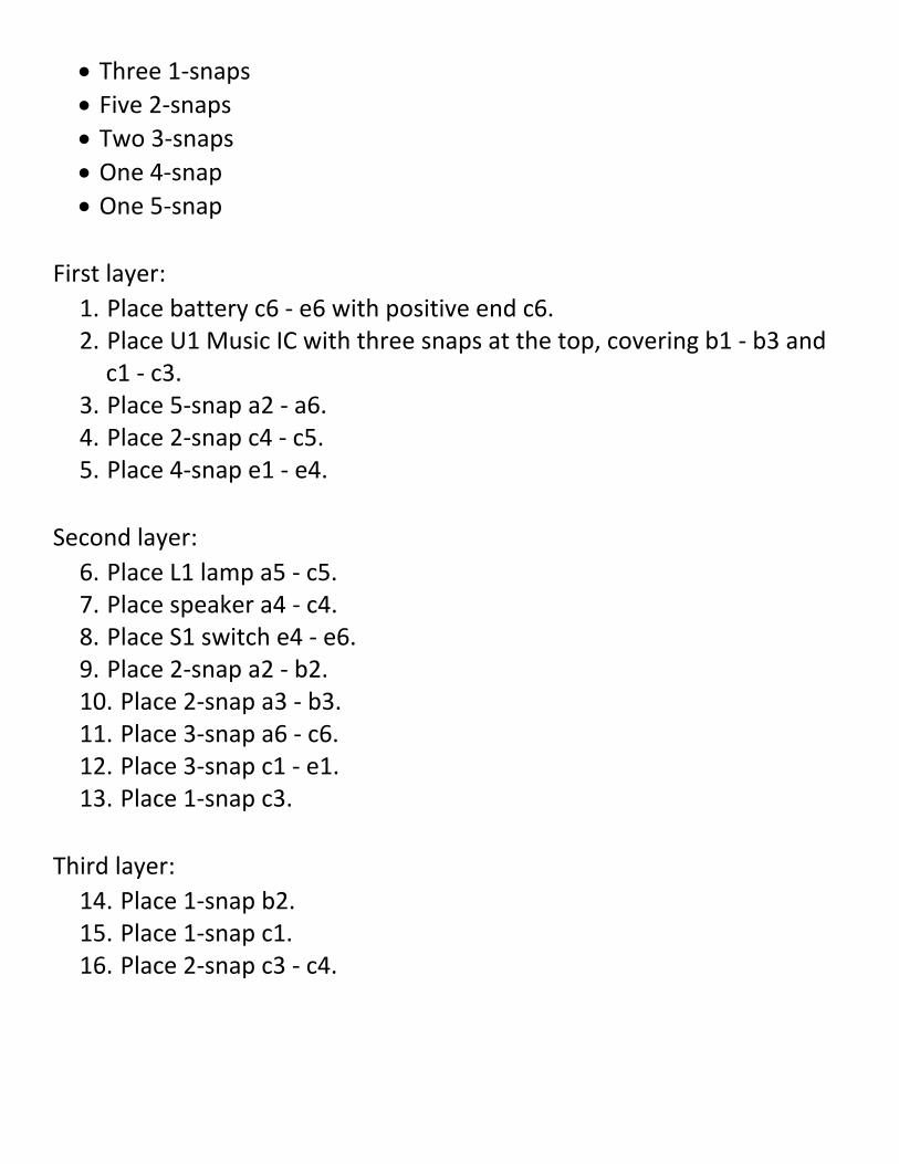
• Three 1-snaps
• Five 2-snaps
• Two 3-snaps
• One 4-snap
• One 5-snap
First layer:
1. Place battery c6 - e6 with positive end c6. 2. Place U1 Music IC with three snaps at the top, covering b1 - b3 and
c1 - c3. 3. Place 5-snap a2 - a6. 4. Place 2-snap c4 - c5. 5. Place 4-snap e1 - e4.
Second layer:
6. Place L1 lamp a5 - c5. 7. Place speaker a4 - c4. 8. Place S1 switch e4 - e6. 9. Place 2-snap a2 - b2. 10. Place 2-snap a3 - b3. 11. Place 3-snap a6 - c6. 12. Place 3-snap c1 - e1. 13. Place 1-snap c3.
Third layer:
14. Place 1-snap b2. 15. Place 1-snap c1. 16. Place 2-snap c3 - c4.

Fourth/fifth layer:
17. Place a 2-snap on the top left and center posts of U2, the Alarm IC, before placing it on the board.
18. Place U2 Alarm IC with three snaps at the top, directly over U1, resting on the two 1-snaps and the 2-snap.
Here the outputs of the Music and Alarm ICs are connected. Turn on the switch and you’ll hear a siren and music together while the lamp varies in brightness.
Project 93: Wackier Sounds
Here are some more sound combinations from the circuit in Project 92.
Remove the 2-snap on top of U2 and place it on the top left and bottom left posts of the same piece. The circuit now works the same way but has different sounds.
Project 94: Really Wacky Sounds
This combines sounds from the Music and Space War ICs.
Parts needed:
• Battery B1
• Switch S1
• Switch S2
• Resistor R1
• Photoresistor RP
• Music IC U1
• Space War IC U3

• Speaker
• Three 1-snaps
• Six 2-snaps
• Three 3-snaps
• One 4-snap
• One 5-snap
• One 6-snap
First layer:
1. Place battery c6 - e6 with positive end c6. 2. Place U1 Music IC with three snaps at the top, covering b1 - b3 and
c1 - c3. 3. Place U3 Space War IC with two snaps at the top, covering d2 - d4
and e2 - e4. 4. Place 4-snap a1 - a4. 5. Place 2-snap a6 - b6. 6. Place 2-snap c5 - d5. 7. Place 6-snap g1 - g6.
Second layer:
8. Place R1 resistor c3 - c5. 9. Place S2 switch e2 - g2. 10. Place RP photoresistor e4 - g4. 11. Place S1 switch e6 - g6. 12. Place 2-snap a2 - b2. 13. Place 2-snap a3 - b3. 14. Place 3-snap a4 - a6. 15. Place 2-snap b6 - c6. 16. Place 5-snap c1 - g1. 17. Place 1-snap d2. 18. Place 2-snap d4 - d5.
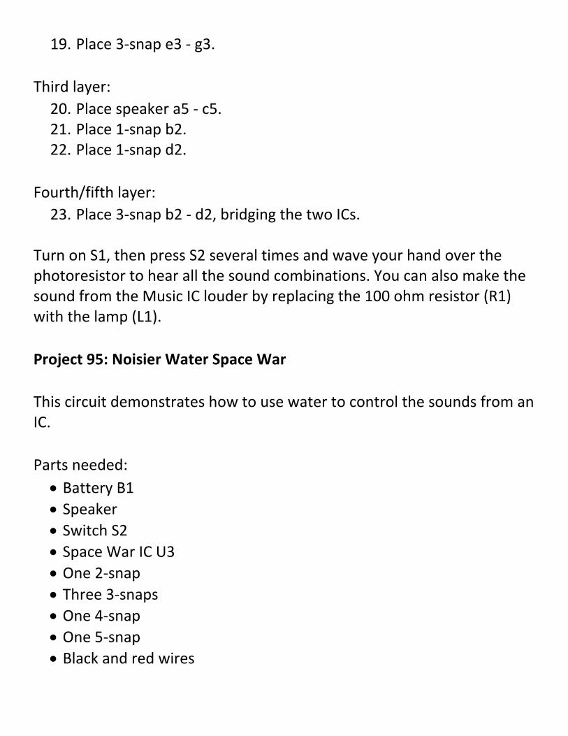
19. Place 3-snap e3 - g3.
Third layer:
20. Place speaker a5 - c5. 21. Place 1-snap b2. 22. Place 1-snap d2.
Fourth/fifth layer:
23. Place 3-snap b2 - d2, bridging the two ICs.
Turn on S1, then press S2 several times and wave your hand over the photoresistor to hear all the sound combinations. You can also make the sound from the Music IC louder by replacing the 100 ohm resistor (R1) with the lamp (L1).
Project 95: Noisier Water Space War
This circuit demonstrates how to use water to control the sounds from an IC.
Parts needed:
• Battery B1
• Speaker
• Switch S2
• Space War IC U3
• One 2-snap
• Three 3-snaps
• One 4-snap
• One 5-snap
• Black and red wires

• Small cup of water
First layer:
1. Place battery c4 - e4 with positive end at c4. 2. Place U3 Space War IC with two snaps at the top, covering c1 - c3
and d1 - d3. 3. Place 5-snap a1 - a5. 4. Place 4-snap f1 - f4.
Second layer:
5. Place speaker a3 - c3. 6. Place S2 switch d1 - f1. 7. Place 3-snap a1 - c1. 8. Place 3-snap a4 - c4. 9. Place 3-snap d2 - f2. 10. Place 2-snap e4 - f4. 11. Place one end of red wire d3. 12. Place one end of black wire f3.
You’ll hear sound if you press switch S2 or if the loose ends of the wires are in the water. Pressing the switch or pulling the wires out of the water changes the sound.
If you prefer, you can just touch the jumper wire metal snaps with your finger instead of putting the jumpers in the water. Wet your finger to get better electrical contact.
Project 96: Light/Water Space War
This is like the previous circuit, but it produces light instead of sound.

Using the circuit built in Project 95, replace the speaker with the LED (D1), positive end at a3. Putting the wire ends in water OR pressing the switch will cause the LED to be bright.
Project 97: OR/AND Space War Light
This circuit also produces light, but with different levels of intensity.
Use the circuit from Project 96 but replace the LED with the 2.5V lamp (L1). Putting the wires in the water OR pressing S2 will cause the lamp to light dimly. Putting the wires in water AND pressing the switch will make the lamp much brighter.
Project 98: Simple Water Alarm
This circuit sounds an alarm when water is detected. It is similar to Project 17 but with jumper wires serving as detectors.
Parts needed:
• Battery B1
• Switch S1
• Alarm IC U2
• Speaker
• Four 2 connectors
• One 4 connector
• One 5 connector
• Red and black wires
• Small cup of water

First layer:
1. Place battery c5 - e5 with positive end c5. 2. Place U2 Alarm IC with three snaps at top, covering c1 - c3 and d1 -
d3. 3. Place speaker b4 - d4. 4. Place 5 snap a1 - a5. 5. Place 4 snap e1 - e4.
Second layer:
6. Place S1 switch a5 - c5. 7. Place 2 snap a4 - b4. 8. Place 2 snap d1 - e1. 9. Place 2 snap d3 - d4. 10. Place 2 snap e4 - e5. 11. Place one end of red wire a2. 12. Place one end of black wire c2.
Leave the wires out of the water at first. When you close switch S1 nothing happens. But place the wire ends in the water and an alarm will sound!
You could use longer wires and lay them on your basement floor. Then if your basement floods during a storm, this circuit will sound an alarm.
Project 99: Simple Salt Water Alarm
This variation of Project 98 detects the presence of salt water.
Add salt to the water in the previous project and the alarm will be louder and faster. Also, try holding the jumper wires with your fingers to see if your body can set off the alarm.

Project 100: Ambulance Water Alarm
This variation of Project 98 makes a different alarm sound.
Use a 1-snap and a 2-snap to connect the left-side terminals of the Alarm IC (located at c1 and d1). The water alarm works the same way, but now it sounds like an ambulance.
Project 101: Ambulance Contact Alarm
Here is another variation of Project 98.
The circuit as it is built can also detect if the wires are touched together. Connect the wires to each other and the sound will be much different. Therefore, the sound of this circuit can tell you if there is water between the contacts or if they are touching each other.

Copyright © 2017 American Printing House for the Blind 1839 Frankfort Avenue Louisville, KY 40206-0085 Phone: 502-895-2405 Toll Free: 800-223-1839 Fax: 502-899-2284 E-mail: [email protected] Website: www.aph.org Snap Circuits® Jr. Access Kit: 1-03041-00 Snap Circuits® Jr. Access Pack: 1-03042-00


