• Maximum capacitance capability in a smaller size• Long life, up to 9,000 hours at +105°C (VR, IR applied)• High ripple current• Excellent surge voltage capability• PET sleeve and Lexan disc are recognized to UL: QMTR2
(UL No. E358957)• Optimized designs available upon request
Overview
The KEMET ALC80 High CV snap-in capacitors offer high performance and reliability in a wide range of case sizes and voltage ratings featuring high ripple currents and long-life performance. Volumetric efficiency ensures the maximum capacitance capability in a smaller size.
Applications
Typical applications for the ALC80 capacitor include inverters, frequency converters, motor drives, motor control, UPS systems, smoothing, energy storage, alternative energy, charging stations, traction, demanding power supplies (SMPS), welding, and HVAC.
Snap-In Aluminum Electrolytic Capacitors
ALC80, +105°C
Part Number System
ALC80 A 392 BB 40Series Termination Capacitance Code (µF) Size Code Rated Voltage (VDC)
Snap-In type Aluminum Electrolytic
See Termination Table First two digits represent significant
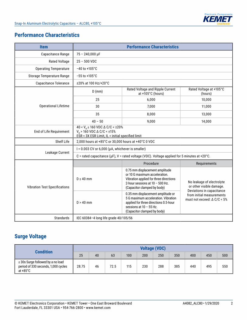
Item Performance CharacteristicsCapacitance Range 75 – 240,000 µF
Rated Voltage 25 – 500 VDC
Operating Temperature −40 to +105°C
Storage Temperature Range −55 to +105°C
Capacitance Tolerance ±20% at 100 Hz/+20°C
Operational Lifetime
D (mm) Rated Voltage and Ripple Current at +105°C (hours)
Rated Voltage at +105°C (hours)
25 6,000 10,000
30 7,000 11,000
35 8,000 13,000
40 – 50 9,000 14,000
End of Life Requirement40 < VR ≤ 160 VDC ∆ C/C < ±20%VR > 160 VDC ∆ C/C < ±15%ESR < 3X ESR Limit, IL < initial specified limit
Shelf Life 2,000 hours at +85°C or 30,000 hours at +40°C 0 VDC
Leakage CurrentI = 0.003 CV or 6,000 (µA, whichever is smaller)
C = rated capacitance (µF), V = rated voltage (VDC). Voltage applied for 5 minutes at +20°C.
Vibration Test Specifications
Procedure Requirements
D ≤ 40 mm
0.75 mm displacement amplitude or 10 G maximum acceleration. Vibration applied for three directions 2-hour sessions at 10 – 500 Hz.(Capacitor clamped by body)
No leakage of electrolyte or other visible damage.
Deviations in capacitance from initial measurements
must not exceed: ∆ C/C < 5%D > 40 mm
0.35 mm displacement amplitude or 5 G maximum acceleration. Vibration applied for three directions 0.5-hour sessions at 10 – 55 Hz. (Capacitor clamped by body)
Standards IEC 60384–4 long life grade 40/105/56
Surge Voltage
ConditionVoltage (VDC)
25 40 63 100 200 250 350 400 450 500
≤ 30s Surge followed by a no load period of 330 seconds, 1,000 cycles at +85°C
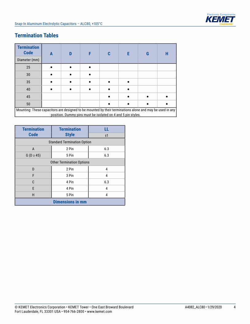
Mounting: These capacitors are designed to be mounted by their terminations alone and may be used in any position. Dummy pins must be isolated on 4 and 5 pin styles.
The capacitance, ESR, and impedance of a capacitor will not change significantly after extended storage periods; however, the leakage current will very slowly increase. KEMET products are particularly stable and allow a shelf life in excess of three years at 40°C. See sectional specification under each product series for specific data.
Re-age (Reforming) Procedure
Apply the rated voltage to the capacitor at room temperature for a period of one hour or until the leakage current has fallen to a steady value below the specified limit. During re-aging, a maximum charging current of twice the specified leakage current or 5 mA (whichever is greater) is suggested.
Reliability
The reliability of a component can be defined as the probability that it will perform satisfactorily under a given set of conditions for a given length of time.
In practice, it is impossible to predict with absolute certainty how any individual component will perform. Therefore, we must utilize probability theory. It is also necessary to clearly define the level of stress involved (e.g., operating voltage, ripple current, temperature, and time.) Finally, the meaning of satisfactory performance must be defined by specifying a set of conditions, which determine the end of life of the component.
KEMET provides an online life calculator that can be used to predict hours of life for a given part number in specific application conditions. This can be found at: https://elc.kemet.com.
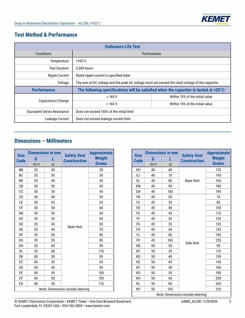
End of Life Definition
Catastrophic failure: short circuit, open circuit or safety vent operation
Parametric Failure:• Change in capacitance > ±15%• Leakage current > initial specified limit• ESR > 3X ESR Limit
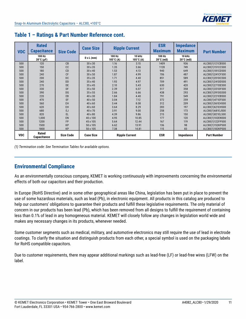
(1) Termination code: See Termination Tables for available options.
Environmental ComplianceAs an environmentally conscious company, KEMET is working continuously with improvements concerning the environmental effects of both our capacitors and their production.
In Europe (RoHS Directive) and in some other geographical areas like China, legislation has been put in place to prevent the use of some hazardous materials, such as lead (Pb), in electronic equipment. All products in this catalog are produced to help our customers' obligations to guarantee their products and fulfill these legislative requirements. The only material of concern in our products has been lead (Pb), which has been removed from all designs to fulfill the requirement of containing less than 0.1% of lead in any homogeneous material. KEMET will closely follow any changes in legislation world wide and makes any necessary changes in its products, whenever needed.
Some customer segments such as medical, military, and automotive electronics may still require the use of lead in electrode coatings. To clarify the situation and distinguish products from each other, a special symbol is used on the packaging labels for RoHS compatible capacitors.
Due to customer requirements, there may appear additional markings such as lead-free (LF) or lead-free wires (LFW) on the label.
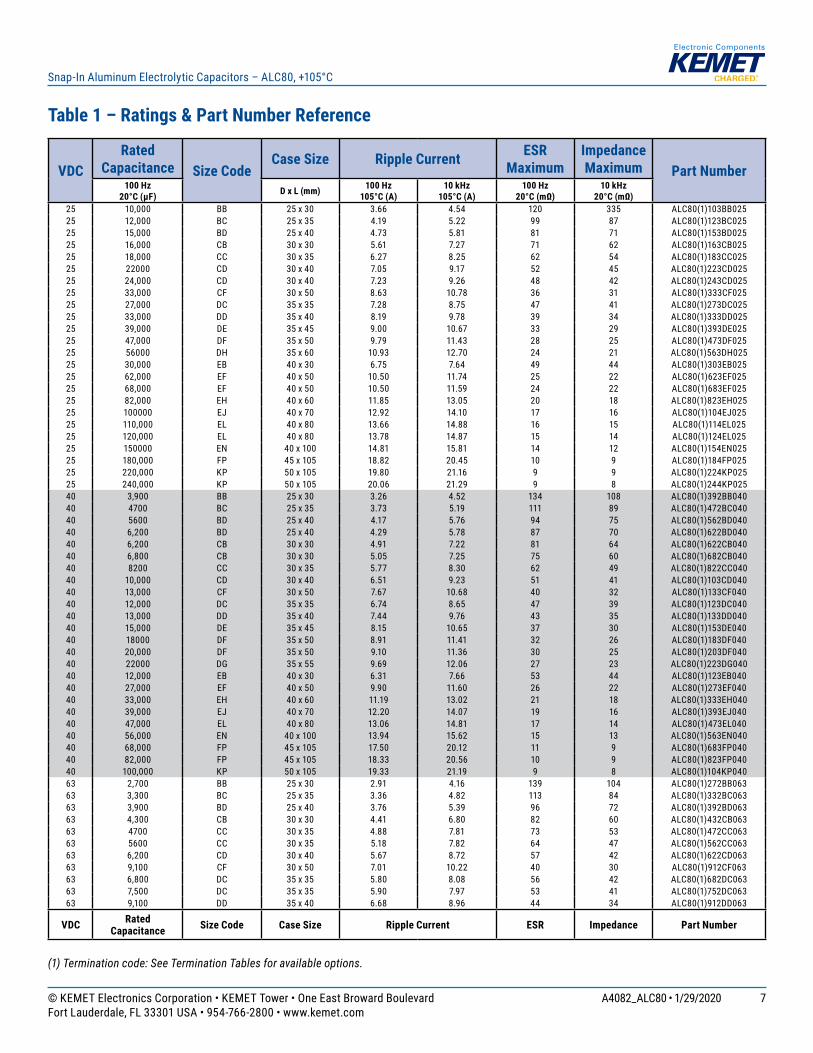
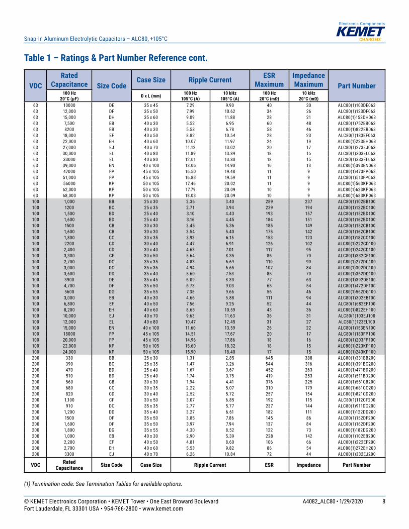
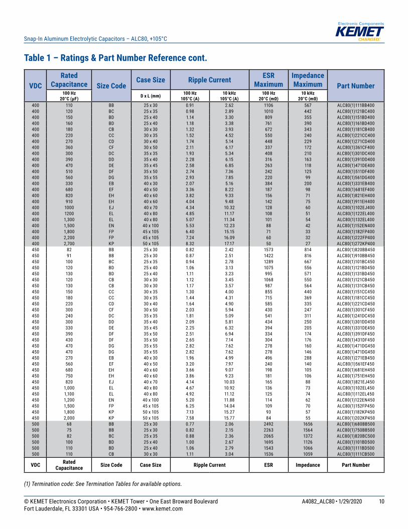
VDCRated
Capacitance Size CodeCase Size Ripple Current ESR
MaximumImpedance Maximum Part Number
100 Hz 20°C (µF) D x L (mm) 100 Hz
105°C (A) 10 kHz
105°C (A)100 Hz
20°C (mΩ)10 kHz
20°C (mΩ)500 120 CB 30 x 30 1.16 3.15 1409 936 ALC80(1)121CB500500 150 CC 30 x 35 1.35 3.66 1128 749 ALC80(1)151CC500500 180 CD 30 x 40 1.53 4.13 940 649 ALC80(1)181CD500500 240 CF 30 x 50 1.87 4.99 706 487 ALC80(1)241CF500500 200 DC 35 x 35 1.71 4.40 851 589 ALC80(1)201DC500500 240 DD 35 x 40 1.93 4.97 709 491 ALC80(1)241DD500500 270 DE 35 x 45 2.10 5.43 630 420 ALC80(1)271DE500500 330 DF 35 x 50 2.39 6.07 517 358 ALC80(1)331DF500500 390 DG 35 x 55 2.66 6.66 438 293 ALC80(1)391DG500500 220 EB 40 x 30 1.84 4.40 791 549 ALC80(1)221EB500500 470 EF 40 x 50 3.04 7.12 372 259 ALC80(1)471EF500500 560 EH 40 x 60 3.44 8.08 312 209 ALC80(1)561EH500500 620 EH 40 x 60 3.64 8.29 283 197 ALC80(1)621EH500500 680 EJ 40 x 70 3.91 9.00 258 173 ALC80(1)681EJ500500 820 EL 40 x 80 4.39 9.86 215 150 ALC80(1)821EL500500 1,000 EN 40 x 100 4.95 10.85 177 120 ALC80(1)102EN500500 1200 FP 45 x 105 5.64 12.44 167 119 ALC80(1)122FP500500 1500 KP 50 x 105 6.62 13.91 136 98 ALC80(1)152KP500500 1800 KP 50 x 105 7.38 14.81 115 83 ALC80(1)182KP500
VDC Rated Capacitance Size Code Case Size Ripple Current ESR Impedance Part Number
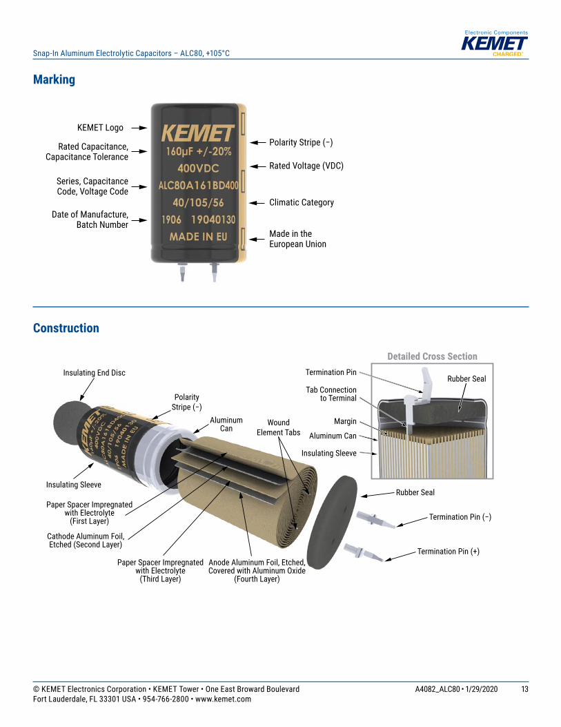
Polarity and Reversed VoltageAluminium Electrolytic capacitors manufactured for use in DC applications contain an anode foil and a cathode foil. As such, they are polarized devices and must be connected with the +ve to the anode foil and the -ve to the cathode foil. If this were to be reversed then the electrolytic process that took place in forming the oxide layer on the anode would be recreated in trying to form an oxide layer on the cathode. In forming the cathode foil in this way, heat would be generated and gas given off within the capacitor, usually leading to catastrophic failure.
The cathode foil already possesses a thin stabilized oxide layer. This thin oxide layer is equivalent to a forming voltage of approximately 2 V. As a result, the capacitor can withstand a voltage reversal of up to 2 V for short periods. Above this voltage, the formation process will commence. Aluminium Electrolytic capacitors can also be manufactured for use in intermittent AC applications by using two anode foils in place of one anode and one cathode.
Mounting PositionThe capacitor can be mounted upright or inclined to a horizontal position. Special attention for the safety vent coverage, which this ensures that internal gas generated can escape when the pressure reaches a certain value due to overstress or catastrophic failure. All mounting positions must allow the safety vent to work properly.
Insulating Resistance≥ 100 MΩ at 100 VDC across insulating sleeve.
Voltage Proof≥ 3,500 VDC across insulating sleeve.≥ 2,500 VAC across insulating sleeve.
Safety VentFor diameters up to 40 mm, the safety vent for overpressure is featured on the base (opposing end to the terminals), and for diameters 45 mm or higher, the safety vent is featured in the side of the can. This is a weakened area in the bottom of the can that is designed to relieve build-up of internal pressure due to overstress or catastrophic failure.
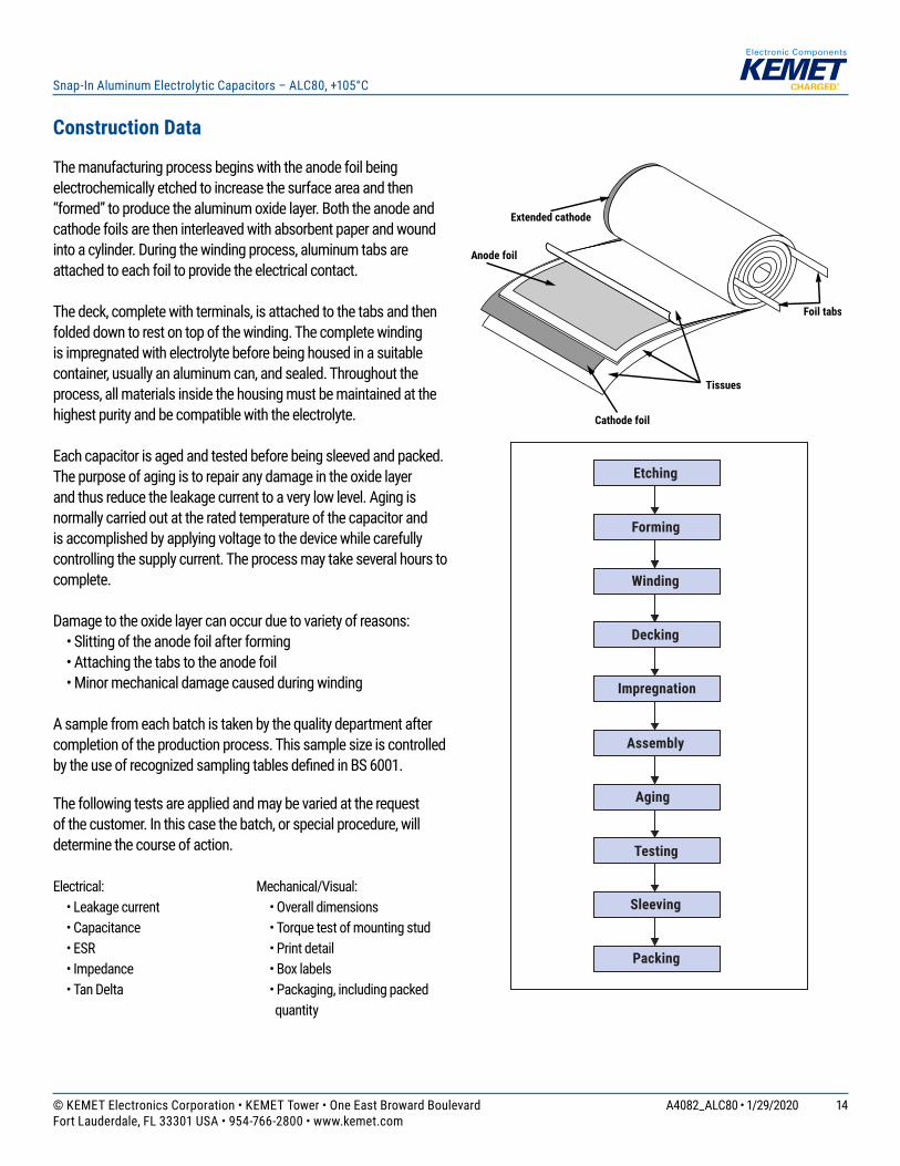
The manufacturing process begins with the anode foil being electrochemically etched to increase the surface area and then “formed” to produce the aluminum oxide layer. Both the anode and cathode foils are then interleaved with absorbent paper and wound into a cylinder. During the winding process, aluminum tabs are attached to each foil to provide the electrical contact.
The deck, complete with terminals, is attached to the tabs and then folded down to rest on top of the winding. The complete winding is impregnated with electrolyte before being housed in a suitable container, usually an aluminum can, and sealed. Throughout the process, all materials inside the housing must be maintained at the highest purity and be compatible with the electrolyte.
Each capacitor is aged and tested before being sleeved and packed. The purpose of aging is to repair any damage in the oxide layer and thus reduce the leakage current to a very low level. Aging is normally carried out at the rated temperature of the capacitor and is accomplished by applying voltage to the device while carefully controlling the supply current. The process may take several hours to complete.
Damage to the oxide layer can occur due to variety of reasons: • Slitting of the anode foil after forming • Attaching the tabs to the anode foil • Minor mechanical damage caused during winding
A sample from each batch is taken by the quality department after completion of the production process. This sample size is controlled by the use of recognized sampling tables defi ned in BS 6001.
The following tests are applied and may be varied at the request of the customer. In this case the batch, or special procedure, will determine the course of action.
Electrical: • Leakage current • Capacitance • ESR • Impedance • Tan Delta
Mechanical/Visual: • Overall dimensions • Torque test of mounting stud • Print detail • Box labels • Packaging, including packed
For a complete list of our global sales offi ces, please visit www.kemet.com/sales.
DisclaimerAll product specifi cations, statements, information and data (collectively, the “Information”) in this datasheet are subject to change. The customer is responsible for checking and verifying the extent to which the Information contained in this publication is applicable to an order at the time the order is placed. All Information given herein is believed to be accurate and reliable, but it is presented without guarantee, warranty, or responsibility of any kind, expressed or implied.
Statements of suitability for certain applications are based on KEMET Electronics Corporation’s (“KEMET”) knowledge of typical operating conditions for such applications, but are not intended to constitute – and KEMET specifi cally disclaims – any warranty concerning suitability for a specifi c customer application or use. The Information is intended for use only by customers who have the requisite experience and capability to determine the correct products for their application. Any technical advice inferred from this Information or otherwise provided by KEMET with reference to the use of KEMET’s products is given gratis, and KEMET assumesno obligation or liability for the advice given or results obtained.
Although KEMET designs and manufactures its products to the most stringent quality and safety standards, given the current state of the art, isolated component failures may still occur. Accordingly, customer applications which require a high degree of reliability or safety should employ suitable designs or other safeguards (such as installation of protective circuitry or redundancies) in order to ensure that the failure of an electrical component does not result in a risk of personal injuryor property damage.
Although all product–related warnings, cautions and notes must be observed, the customer should not assume that all safety measures are indicted or that other measures may not be required.
KEMET is a registered trademark of KEMET Electronics Corporation.