51
PRESENTATION TITLE GOES HERE SNIA Power Meter Workshop SNIA Emerald TM Training SNIA Emerald Power Efficiency Measurement Specification, for use in EPA ENERGY STAR ® July 14-17, 2014

PRESENTATION TITLE GOES HERE SNIA Power Meter Workshop
SNIA EmeraldTM Training
SNIA Emerald Power Efficiency
Measurement Specification,
for use in EPA ENERGY STAR®
July 14-17, 2014

presented by
Chroma System Solutions, Inc.
SNIA Hands-On Power Meter Workshop

Work Shop Overview
• Power Meter Basic’s
• Manual Operation of Power Meter
• Remote Interface and Software operation of Power Meter
• External Current Sensors (Shunts & Current Transformers)
• AC Source requirements for consistent and compatible
measurements.
• Q & A
Power Meter Basic’s
Power Meter Workshop
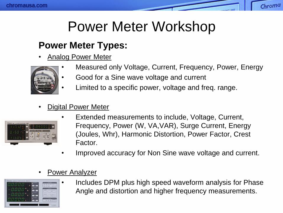
Power Meter Types: • Analog Power Meter
• Measured only Voltage, Current, Frequency, Power, Energy
• Good for a Sine wave voltage and current
• Limited to a specific power, voltage and freq. range.
• Digital Power Meter
• Extended measurements to include, Voltage, Current,
Frequency, Power (W, VA,VAR), Surge Current, Energy
(Joules, Whr), Harmonic Distortion, Power Factor, Crest
Factor.
• Improved accuracy for Non Sine wave voltage and current.
• Power Analyzer
• Includes DPM plus high speed waveform analysis for Phase
Angle and distortion and higher frequency measurements.

Power Meter applications: • Power Measurements for Energy Consumption (Joules, Whr)
• Accurate measurements for manufacturers products to meet various
energy standards. Note: a printer left on in standby mode can consume
408Kwr per year. A refrigerator 20CF can consume as much as
1700Kwhr per year. (1Whr = 3600 Joules)
• Power Measurements to determine Efficiency
• New Standards and Guidelines have increased the need for Power
Meters, due to power conservation
• Energy Guidelines for improved efficiency, from NREL, DOE, IEC, ISO,
CEC, Energy Star
• Measurements for Harmonic Distortion (THDv & THDi)
• Utilities concern that distortion causing stress on the grid’s hardware.
• Concerns of Consumers equipment affected by Noise and Harmonics
generated by devices connected to the grid including EMI.
Power Meter Workshop

Power Meter Measurements:
Power Meters should have the ability to measure or extract the following:
• Voltage RMS, Voltage Peak + and – (continuous)
• Current RMS, Current Peak + and -- (continuous),
Surge Current (Instantaneous)
• Power Factor
• Crest Factor
• Watts, VA, VAR
• Energy (Whrs, Joules)
• THDi, THDv
And all measurements should have Accuracy better than 1%
With Sample rates greater than 100Khz
Power Meter Workshop

Power Meter Requirements per Energy Star 6.0 for Computers
Power Meter: Power meters shall have the following attributes:
1.Current Crest Factor:
a.) An available crest factor of 3 or more at its rated range value; and
b.) A current range of 10 milliamperes .or less
2.Minimum Frequency Response: 3.0Khz
3.Minimum Resolution:
a.) 0.01W for measurement values less than 10W;
b.) 0.1W for measurement values from 10W to 100W; and
c.) 1.0W for measurement values greater than 100W
4.Measurement Accuracy:
a.) Power measurements with a value greater than or equal to 0.5W shall
be made with an accuracy of less than 2%
b.) Power measurements with a value of less than 0.5W shall be made
with an accuracy of less than +/- 0.01W (2% at 0.5W)

Power Source Requirements per Energy Star 6.0 for Computers

Voltage
Sense
Analog to Digital
Converter (ADC)
Analog to Digital
Converter (ADC)
Current
Sense
Digital Signal Processor (DSP)
Zero Crossing
Detector
Memory Embedded Firmware
with Algorithms
Power Meter Workshop Digital Power Meter:
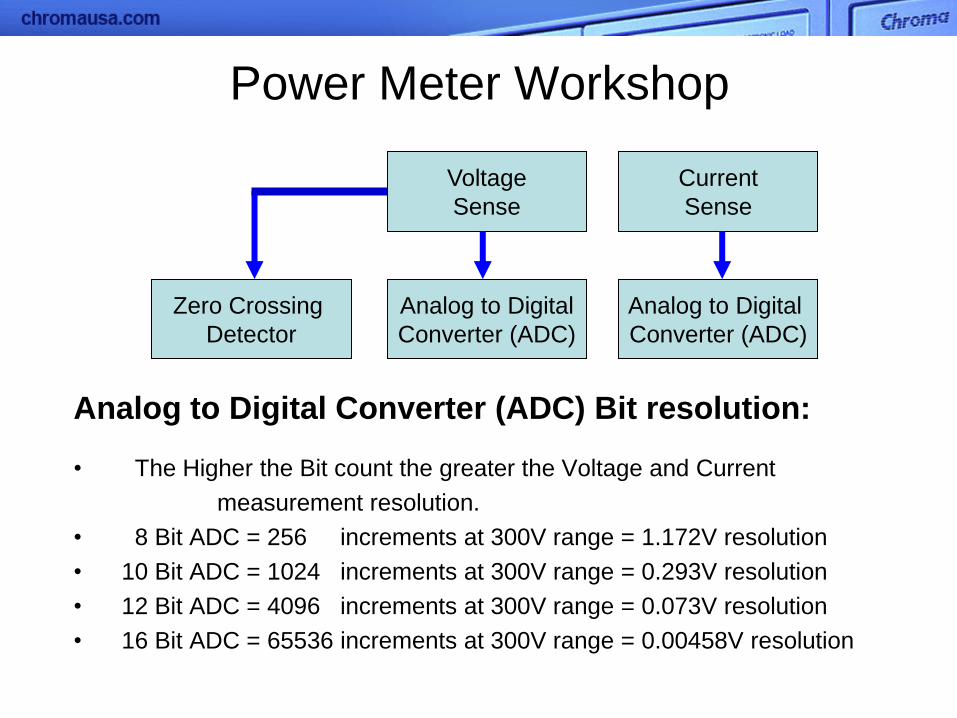
Voltage
Sense
Analog to Digital
Converter (ADC)
Analog to Digital
Converter (ADC)
Current
Sense
Zero Crossing
Detector
Power Meter Workshop
Analog to Digital Converter (ADC) Bit resolution:
• The Higher the Bit count the greater the Voltage and Current
measurement resolution.
• 8 Bit ADC = 256 increments at 300V range = 1.172V resolution
• 10 Bit ADC = 1024 increments at 300V range = 0.293V resolution
• 12 Bit ADC = 4096 increments at 300V range = 0.073V resolution
• 16 Bit ADC = 65536 increments at 300V range = 0.00458V resolution

Power Meter Basics
If Voltage and Current Waveforms were pure sinewaves and loads were pure
resistive the power measurements could be simply taking the Peak voltage and
peak current x 0.707 to create the Vrms and Irms and the multiply the 2
together.
True Power or Watts = Vrms x Irms x cos θ Vrms = Vpk x 0.707 Irms = Ipk x 0.707 cos θ or PF = W/(Vrms x Irms) Ex. 120Vrms x 10Arms x 0.9PF = 1080W
Resistive
Load
Inductive
Load

Power Meter Basics (Sample Rates)
Real world voltage and current waveforms are seldom sinusoidal
Digital Power Meters Sample Rates are critical to accuracy .
Sample rate of approx 1024
samples per second equates
to approx one measurement
every millisecond and only 20
measurements per cycle at
50hz. At 800Hz it equates to
1.25 measurements per cycle.
In the example waveform the
Peak current would be missed.
Chroma 66202 Sample rate is
240K Samples/Sec

Power Meter Basics Harmonic Distortion Measurements for a specific harmonic: Digital Power Meters use DSP’s for a digital equivalent of a Digital Bandpass
Filter to extract the voltage and current at a specific harmonic. Then measured
using the RMS measurement algorithms for RMS Voltage and RMS Current at
each Harmonic.
BandPass Filter Graph
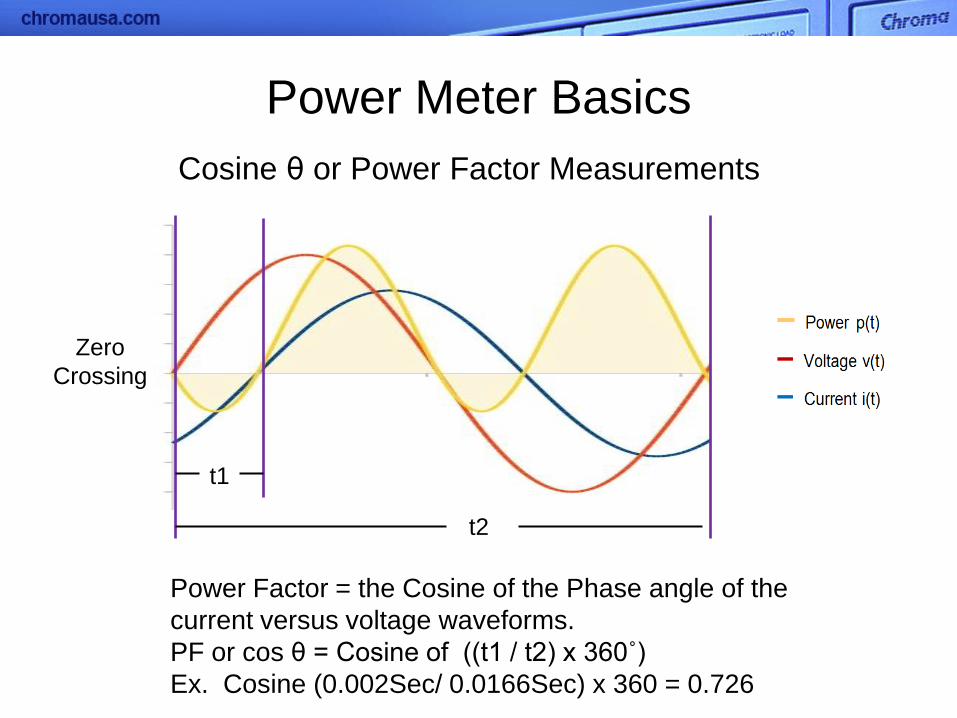
Power Meter Basics
Cosine θ or Power Factor Measurements
Power Factor = the Cosine of the Phase angle of the
current versus voltage waveforms.
PF or cos θ = Cosine of ((t1 / t2) x 360˚)
Ex. Cosine (0.002Sec/ 0.0166Sec) x 360 = 0.726
t1
t2
Zero
Crossing
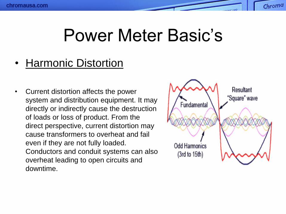
• Harmonic Distortion
• Current distortion affects the power
system and distribution equipment. It may
directly or indirectly cause the destruction
of loads or loss of product. From the
direct perspective, current distortion may
cause transformers to overheat and fail
even if they are not fully loaded.
Conductors and conduit systems can also
overheat leading to open circuits and
downtime.
Power Meter Basic’s
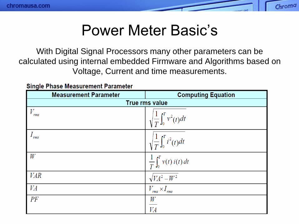
With Digital Signal Processors many other parameters can be
calculated using internal embedded Firmware and Algorithms based on
Voltage, Current and time measurements.
Power Meter Basic’s
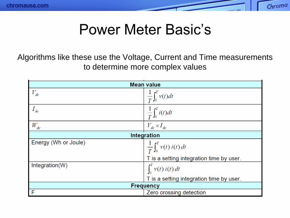
Power Meter Basic’s
Algorithms like these use the Voltage, Current and Time measurements
to determine more complex values

Power Meter Basic’s
Algorithms like these use the Voltage, Current and Time measurements
to determine more complex values
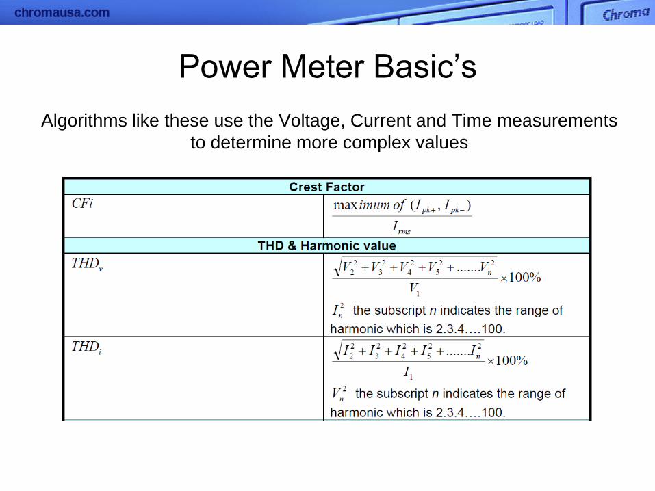
Power Meter Basic’s
Algorithms like these use the Voltage, Current and Time measurements
to determine more complex values
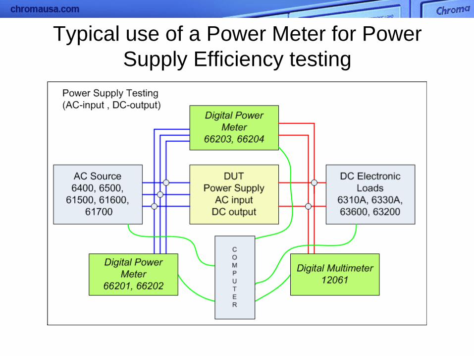
Typical use of a Power Meter for Power
Supply Efficiency testing

Typical use of a Power Meter for Power
Supply Efficiency testing
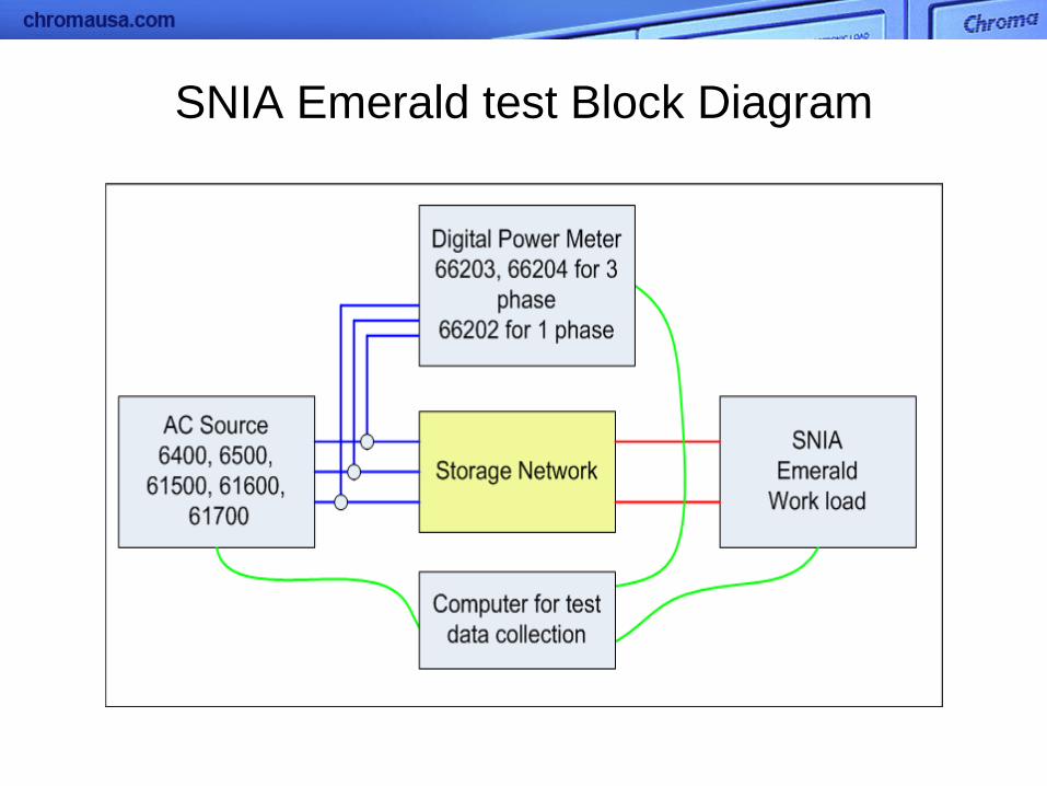
SNIA Emerald test Block Diagram

Manual Operation of
Power Meter (Chroma 66202)
Manual Operation of
Power Meter (Chroma 66202)
3 1 2
7 9 10 11 12 8
4 5 6
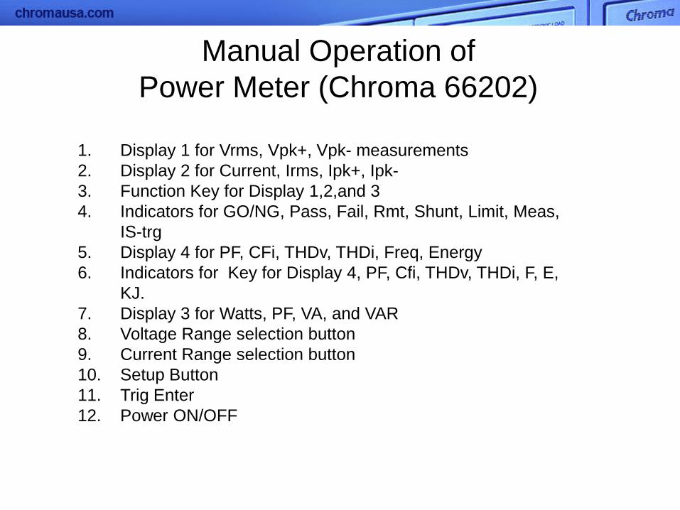
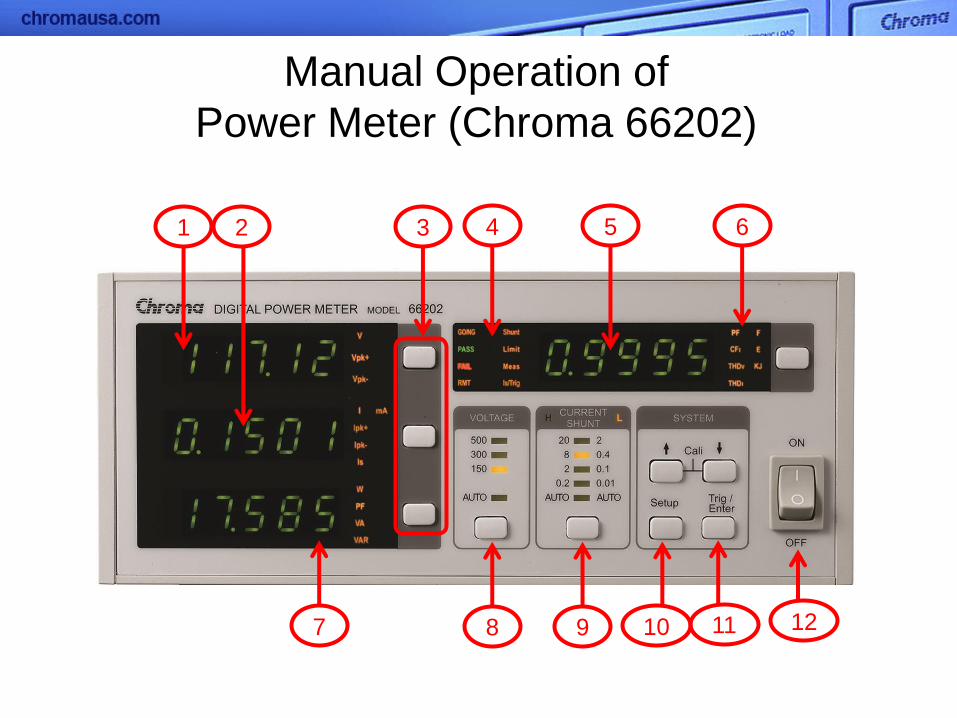
Manual Operation of
Power Meter (Chroma 66202)
1. Display 1 for Vrms, Vpk+, Vpk- measurements
2. Display 2 for Current, Irms, Ipk+, Ipk-
3. Function Key for Display 1,2,and 3
4. Indicators for GO/NG, Pass, Fail, Rmt, Shunt, Limit, Meas,
IS-trg
5. Display 4 for PF, CFi, THDv, THDi, Freq, Energy
6. Indicators for Key for Display 4, PF, Cfi, THDv, THDi, F, E,
KJ.
7. Display 3 for Watts, PF, VA, and VAR
8. Voltage Range selection button
9. Current Range selection button
10. Setup Button
11. Trig Enter
12. Power ON/OFF
Manual Operation of
Power Meter (Chroma 66202)
3 1
2
7 9 8
4 5
6
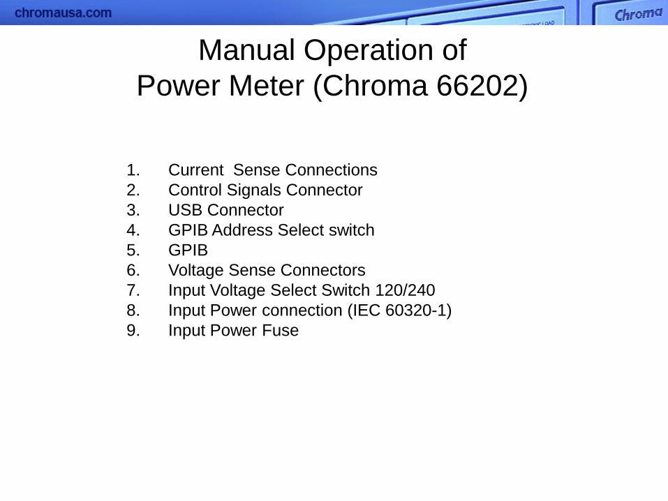
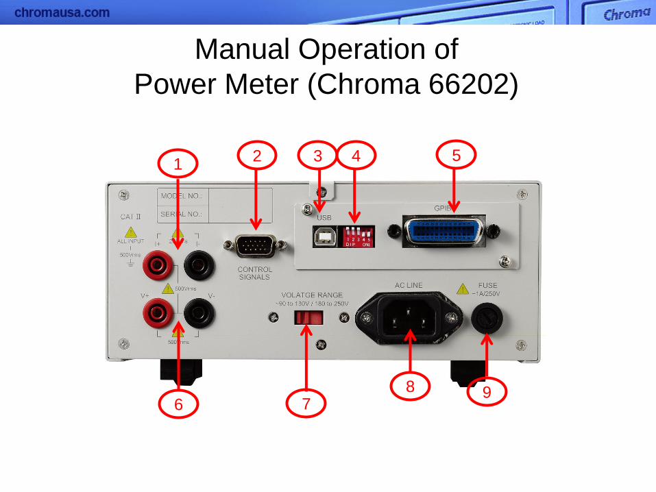
Manual Operation of
Power Meter (Chroma 66202)
1. Current Sense Connections
2. Control Signals Connector
3. USB Connector
4. GPIB Address Select switch
5. GPIB
6. Voltage Sense Connectors
7. Input Voltage Select Switch 120/240
8. Input Power connection (IEC 60320-1)
9. Input Power Fuse

Chroma 66202 Power Meter
------------------------------------------------------------------------------
------------------------------------------------------------------------------
------------------------------------------------------------------------------
------------------------------------------------------------------------------
------------------------------------------------------------------------------
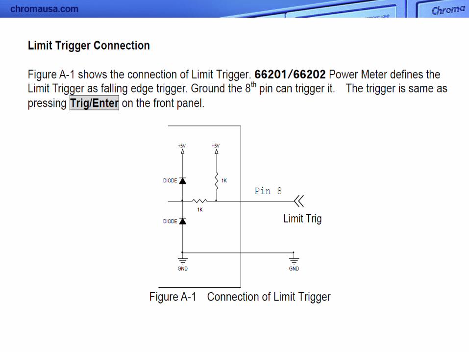
Control
Signal
Connector
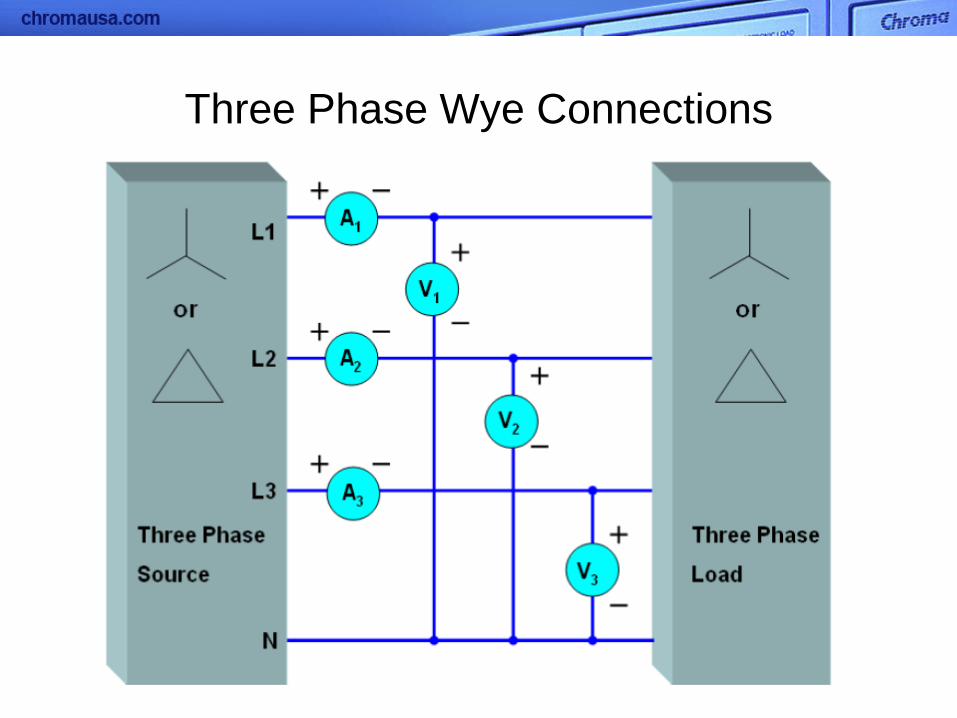
Three Phase Wye Connections

External Current Transformer
& Current Shunt
Switch to Live WebCam
focused on 66202
For Manual Operating
Instructions and
Reference User Manual

Software for Power Meter
(Chroma 66202)
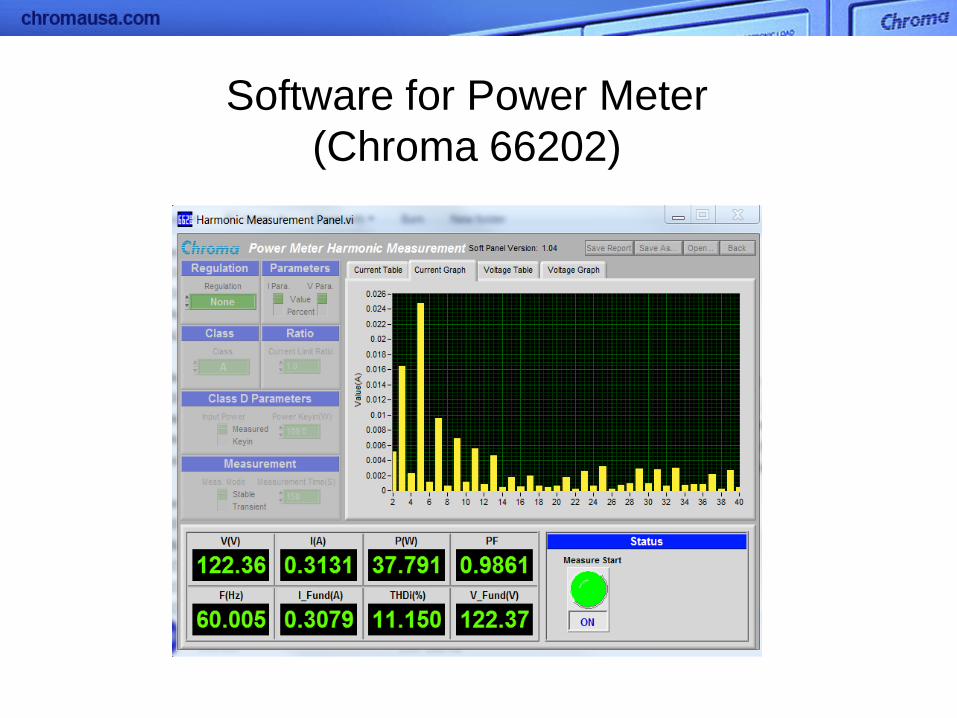
Software for Power Meter
(Chroma 66202)

• Voltage Range : 15/30/60/150/300/600 Vrms
• Current Range :
0.005/0.02/0.05/0.2/0.5/2/5/20 Arms
• Frequency Range : DC, 15Hz~10kHz
• Support different wiring configuration power
measurement (1P2W/1P3W/3P3W/3P4W)
• Support external shunt and CT for higher
current measurement application
• 5 mA minimum current range & 0.1mW
power resolution
• Meets ENERGY STAR / IEC 62301
measurement requirements
• Inrush current and energy measurement
• Voltage/ Current harmonics measurement
up to 50 orders
Digital Power Meter Multi-Channel
66201,66202
66203,66204
Chroma Digital Power Meters

AC Power Supply or Source
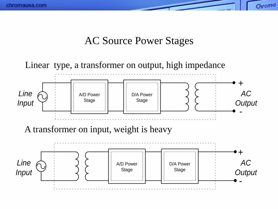
AC Source Power Stages
A/D Power
Stage
D/A Power
Stage
Line
Input
AC
Output
+
-
A transformer on input, weight is heavy
Linear type, a transformer on output, high impedance
A/D Power
Stage
D/A Power
Stage
Line
Input
AC
Output
+
-
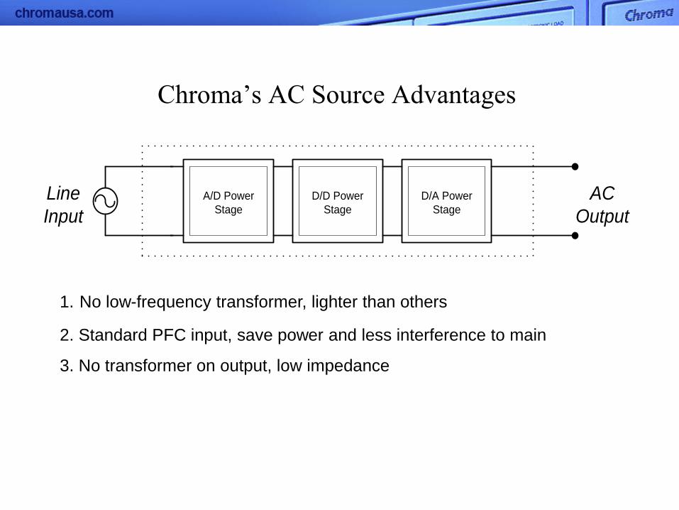
Chroma’s AC Source Advantages
1. No low-frequency transformer, lighter than others
2. Standard PFC input, save power and less interference to main
3. No transformer on output, low impedance
A/D Power
Stage
D/A Power
Stage
Line
Input
AC
Output
D/D Power
Stage
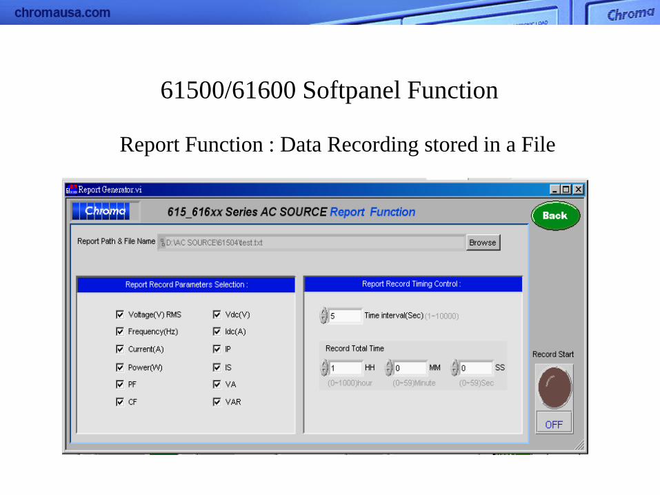
Report Function : Data Recording stored in a File
61500/61600 Softpanel Function
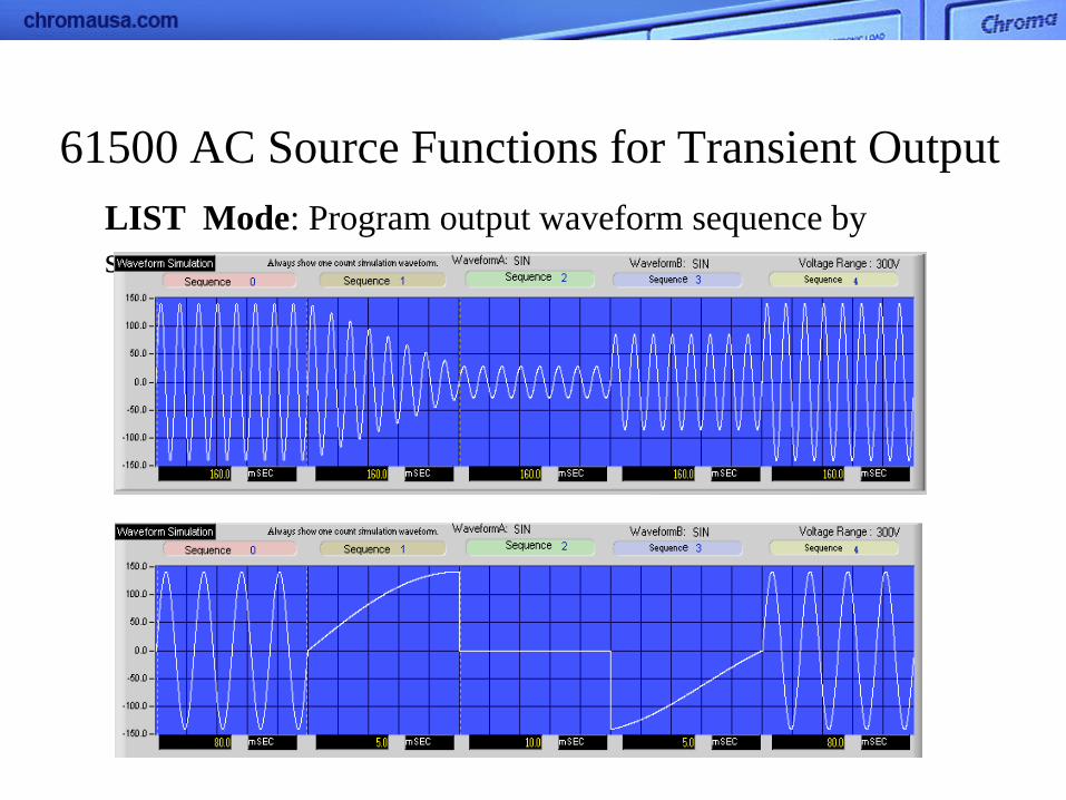
61500 AC Source Functions for Transient Output
LIST Mode: Program output waveform sequence by
sequence

61500 AC Source Functions for Transient Output PULSE Mode: Insert a waveform into normal voltage
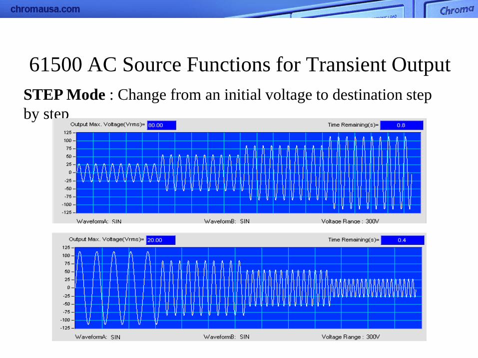
61500 AC Source Functions for Transient Output
STEP Mode : Change from an initial voltage to destination step
by step

Transient Output with High Voltage
2 units of AC Source with synchronizing signal:
Use 3-phase Mode, 61500/61600 as the Master, 61500 as the Slave.
Master: Fixed Mode 220V
Slave: List Mode 180V/0.5 sec
220V with 400V/0.5s transient L
L
N
N
UUT
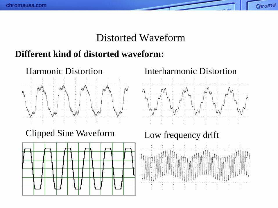
Distorted Waveform
Harmonic Distortion Interharmonic Distortion
Clipped Sine Waveform Low frequency drift
Different kind of distorted waveform:
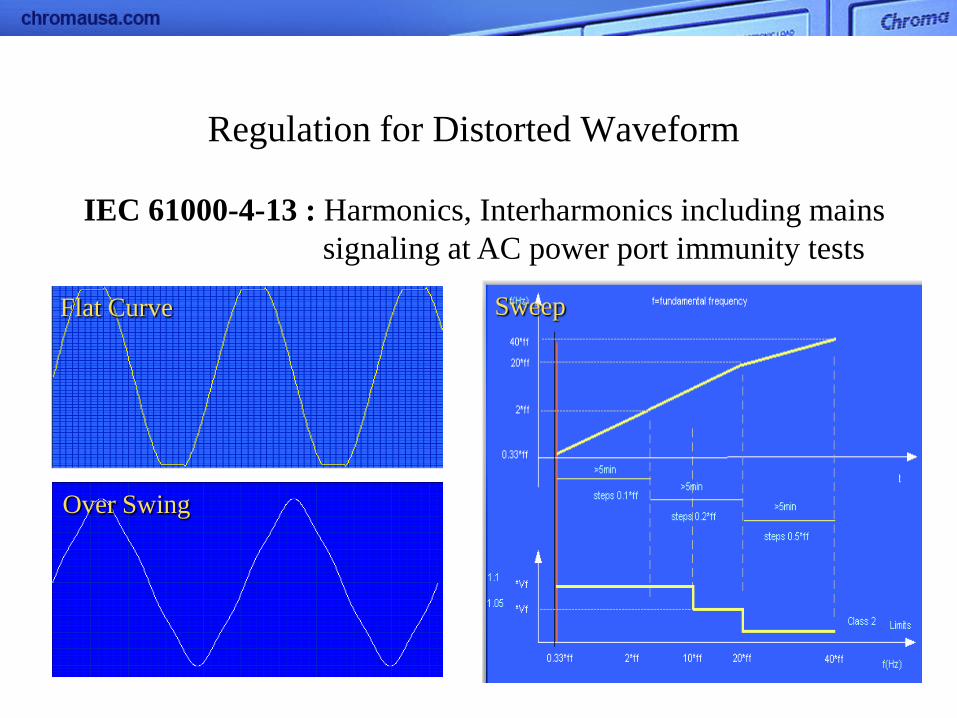
IEC 61000-4-13 : Harmonics, Interharmonics including mains
signaling at AC power port immunity tests
Flat Curve
Over Swing
Sweep
Regulation for Distorted Waveform

SYNTHESIS : Edit harmonic components (Amplitude & Phase)
of 40 orders to synthesize a new waveform.
(50/60Hz)
61500‘s Functions for Distorted Waveform
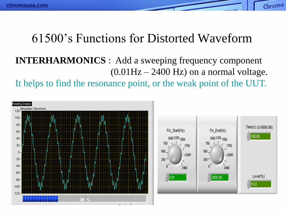
INTERHARMONICS : Add a sweeping frequency component
(0.01Hz – 2400 Hz) on a normal voltage.
It helps to find the resonance point, or the weak point of the UUT.
61500’s Functions for Distorted Waveform

WAVEFORM EDITOR : Edit waveform by harmonic orders on
softpanel, send the data and save to
User
Waveform of AC Source.
It can be used on every frequency but less accuracy.
61500‘s Functions for Distorted Waveform
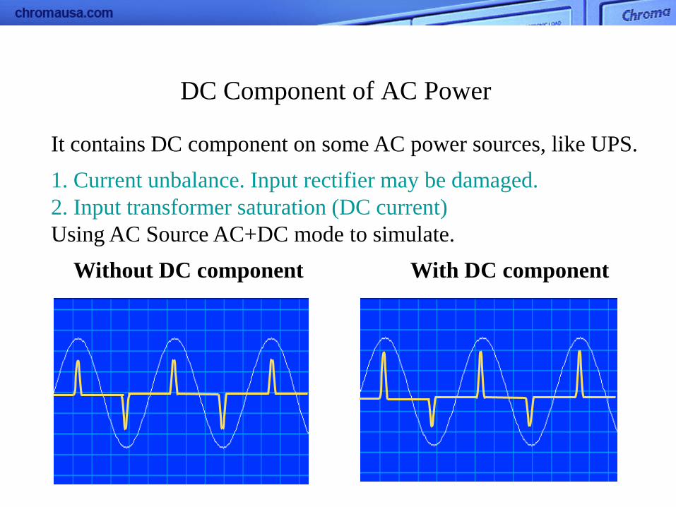
It contains DC component on some AC power sources, like UPS.
1. Current unbalance. Input rectifier may be damaged.
2. Input transformer saturation (DC current)
Using AC Source AC+DC mode to simulate.
Without DC component With DC component
DC Component of AC Power


