Thank you for purchasing the OMRON SNMP/Web card lately
Correspondence specification
This product is equipment which makes network connection possible by inserting in the slot of the OMRON uninterruptible power supply (UPS).
Functional feature
By inserting this product in an uninterruptible power supply (UPS), status acquisition from an uninterruptible power supply (UPS) and command issue to an uninterruptible power supply (UPS) are enabled.
By inserting this product in an uninterruptible power supply (UPS), an uninterruptible power supply (UPS) is manageable even from the personal computer which does not carry a serial port.
Offer of automatic shutdown software
Automatic shutdown software is enclosed by this product. (Please look at the newest
information by our homepage.)
It is possible to shut down by setup in the following cases.
When a main power supply system is downed
When the battery of an uninterruptible power supply (UPS) falls
When the connection capacity of an uninterruptible power supply (UPS) exceeds
When the temperature of an uninterruptible power supply (UPS) rises
Automatic shutdown software and a script shutdown can perform schedule operation.
A computer can be safely suspended by automatic shutdown software and script shutdown.
Be related with the license of automatic shutdown software.
You can use this product for two or more computers which perform shutdown via a network by
installing it.
About export of this product
When you wish issue of parameter sheet, please apply to our homepage.
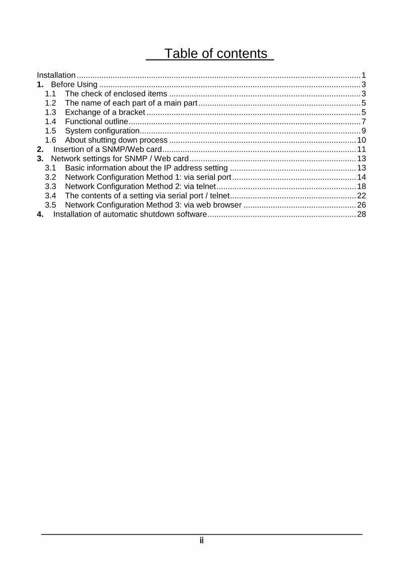
1.5 System configuration .................................................................................................. 9
1.6 About shutting down process ................................................................................... 10
2. Insertion of a SNMP/Web card ...................................................................................... 11
3. Network settings for SNMP / Web card .......................................................................... 13
3.1 Basic information about the IP address setting ........................................................ 13
3.2 Network Configuration Method 1: via serial port ....................................................... 14
3.3 Network Configuration Method 2: via telnet .............................................................. 18
3.4 The contents of a setting via serial port / telnet ........................................................ 22
3.5 Network Configuration Method 3: via web browser .................................................. 26
4. Installation of automatic shutdown software .................................................................. 28
1
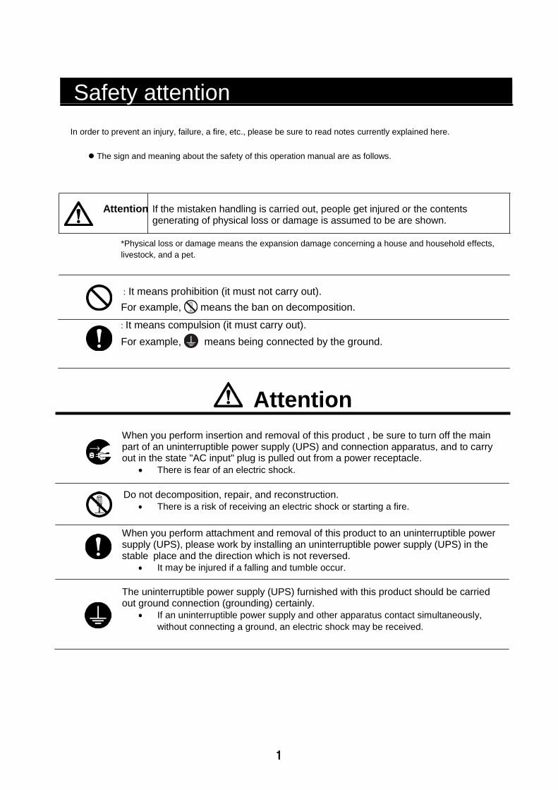
Safety attention
In order to prevent an injury, failure, a fire, etc., please be sure to read notes currently explained here.
The sign and meaning about the safety of this operation manual are as follows.
Attention If the mistaken handling is carried out, people get injured or the contents generating of physical loss or damage is assumed to be are shown.
*Physical loss or damage means the expansion damage concerning a house and household effects,
livestock, and a pet.
: It means prohibition (it must not carry out).
For example, means the ban on decomposition.
: It means compulsion (it must carry out).
For example, means being connected by the ground.
Attention
When you perform insertion and removal of this product , be sure to turn off the main part of an uninterruptible power supply (UPS) and connection apparatus, and to carry out in the state "AC input" plug is pulled out from a power receptacle.
There is fear of an electric shock.
Do not decomposition, repair, and reconstruction.
There is a risk of receiving an electric shock or starting a fire.
When you perform attachment and removal of this product to an uninterruptible power supply (UPS), please work by installing an uninterruptible power supply (UPS) in the stable place and the direction which is not reversed.
It may be injured if a falling and tumble occur.
The uninterruptible power supply (UPS) furnished with this product should be carried out ground connection (grounding) certainly.
If an uninterruptible power supply and other apparatus contact simultaneously,
without connecting a ground, an electric shock may be received.
2
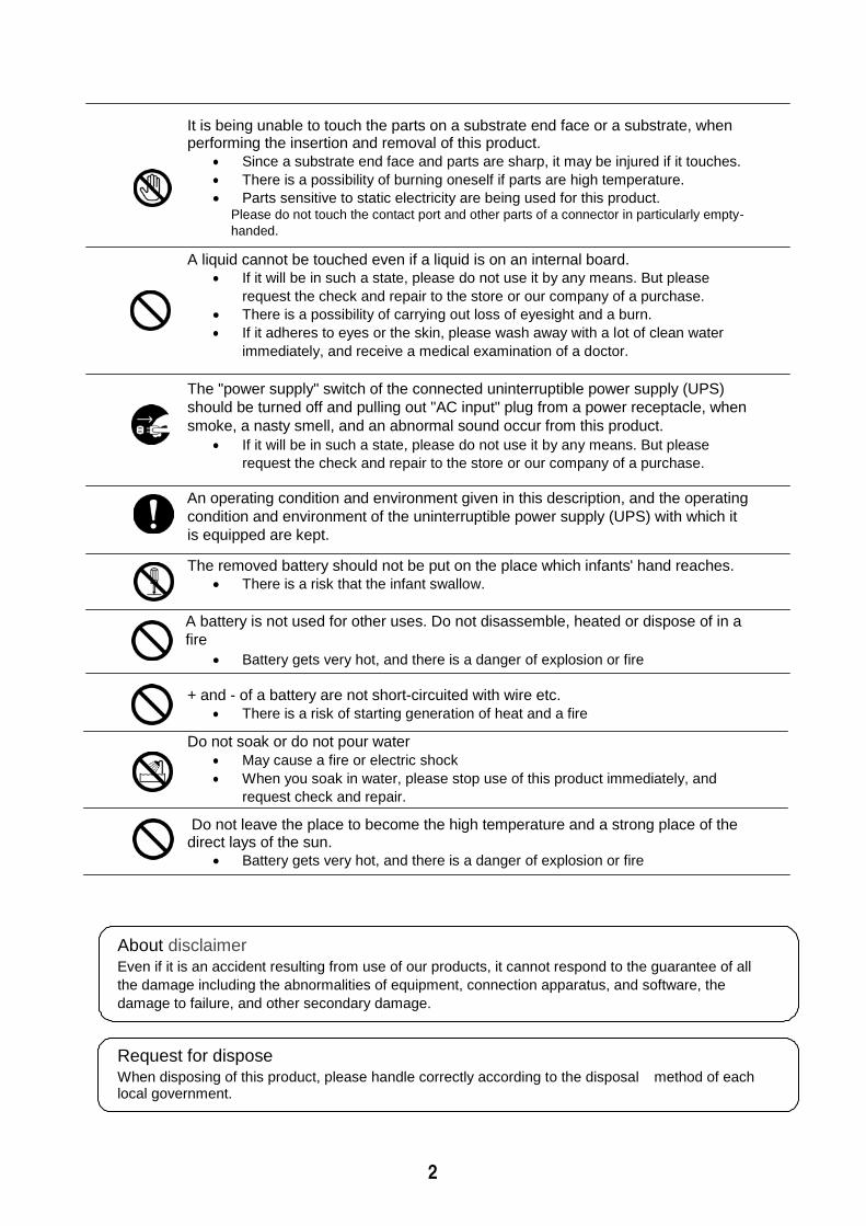
It is being unable to touch the parts on a substrate end face or a substrate, when performing the insertion and removal of this product.
Since a substrate end face and parts are sharp, it may be injured if it touches.
There is a possibility of burning oneself if parts are high temperature.
Parts sensitive to static electricity are being used for this product. Please do not touch the contact port and other parts of a connector in particularly empty-
handed.
A liquid cannot be touched even if a liquid is on an internal board. If it will be in such a state, please do not use it by any means. But please
request the check and repair to the store or our company of a purchase.
There is a possibility of carrying out loss of eyesight and a burn.
If it adheres to eyes or the skin, please wash away with a lot of clean water
immediately, and receive a medical examination of a doctor.
The "power supply" switch of the connected uninterruptible power supply (UPS)
should be turned off and pulling out "AC input" plug from a power receptacle, when
smoke, a nasty smell, and an abnormal sound occur from this product.
If it will be in such a state, please do not use it by any means. But please
request the check and repair to the store or our company of a purchase.
An operating condition and environment given in this description, and the operating
condition and environment of the uninterruptible power supply (UPS) with which it
is equipped are kept.
The removed battery should not be put on the place which infants' hand reaches. There is a risk that the infant swallow.
A battery is not used for other uses. Do not disassemble, heated or dispose of in a
fire
Battery gets very hot, and there is a danger of explosion or fire
+ and - of a battery are not short-circuited with wire etc.
There is a risk of starting generation of heat and a fire
Do not soak or do not pour water
May cause a fire or electric shock
When you soak in water, please stop use of this product immediately, and
request check and repair.
Do not leave the place to become the high temperature and a strong place of the direct lays of the sun.
Battery gets very hot, and there is a danger of explosion or fire
About disclaimer Even if it is an accident resulting from use of our products, it cannot respond to the guarantee of all
the damage including the abnormalities of equipment, connection apparatus, and software, the
damage to failure, and other secondary damage.
Request for dispose When disposing of this product, please handle correctly according to the disposal method of each local government.
3
1. Before Using
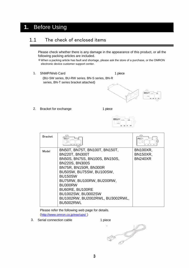
1.1 The check of enclosed items
Please check whether there is any damage in the appearance of this product, or all the following packing articles are included.
*When a packing article has fault and shortage, please ask the store of a purchase, or the OMRON
Direct connection of an uninterruptible power supply (UPS) and a network
By inserting into an uninterruptible power supply (UPS) this product, you can manage an
uninterruptible power supply (UPS) from any computer that is not equipped with a serial
port.
By inserting into an uninterruptible power supply (UPS) this product, you can manage
an uninterruptible power supply (UPS) from a Web browser and SNMP manager
software available on the market.
Remote monitoring of the uninterruptible power supply (UPS) on the network
From all workstations on the intranet and the Internet, you can remotely monitor the
uninterruptible power supply (UPS).
You can set the function of SNMP / Web card and the uninterruptible power supply (UPS) from a computer on the network
Parameter settings for SNMP / Web card and the uninterruptible power supply (UPS)
can be carried out in the Internet browser or via any of the SNMP management
station. (Function as an SNMP agent can be set over a serial connection and Telnet.)
Display the contents of the parameter setting screen is automatically changed
according to (presence or absence of output outlet control function) the contents of the
function of the uninterruptible power supply (UPS), only the required setting items are
displayed.
Enhanced security features
It corresponds also to HTTPS and SNMPv3 in addition to HTTP and
SNMPv1. (Cautions) Access by HTTPS can be accessed by Open SSL
ver.2.0.Access by HTTPS cannot be performed in some browser software
(Firefox etc.).
Mail Notification You can send a notification email to the address that you specified in advance in the
event of a power failure, etc.
Log function
The power failure (UPS), power status, battery status and uninterruptible power supply
can be stored in flash memory in the product.
It corresponds to Syslog.
Automatic shutdown function
By installing the enclosed automatic shutdown software, the predetermined
shutdown which the administrator programmed beforehand, or a shutdown when
serious power failure occurs is performed automatically.
The function corresponding to Wake ON LAN By registering a maximum of 32 MAC Addresses of client PC which has equipped the
WakeOnLAN function, all the client PCs can be rebooted at once with a Wake ON
LAN signal at the time of an uninterruptible power supply (UPS) reboot after the
shutdown by the signal from an uninterruptible power supply (UPS).
8
Standard MIB (RFC1628) and original MIB (swc mib) of an uninterruptible power supply (UPS) are equipped.
Using a JAVA applet, the state of a power supply is monitored By a graphical representation, the state of a power supply can be checked visually.
Script shutdown
You can shut down the computer from the network by incorporating the script without
using the auto-shutdown software.
Down monitoring Monitored via a network device that is connected to an uninterruptible power supply
(UPS), you can stop / start the output of the UPS when an error occurs.
CO2 setting The result of having computed the carbon-dioxide emissions of the apparatus (whole)
connected to the uninterruptible power supply (UPS) is displayed.
9
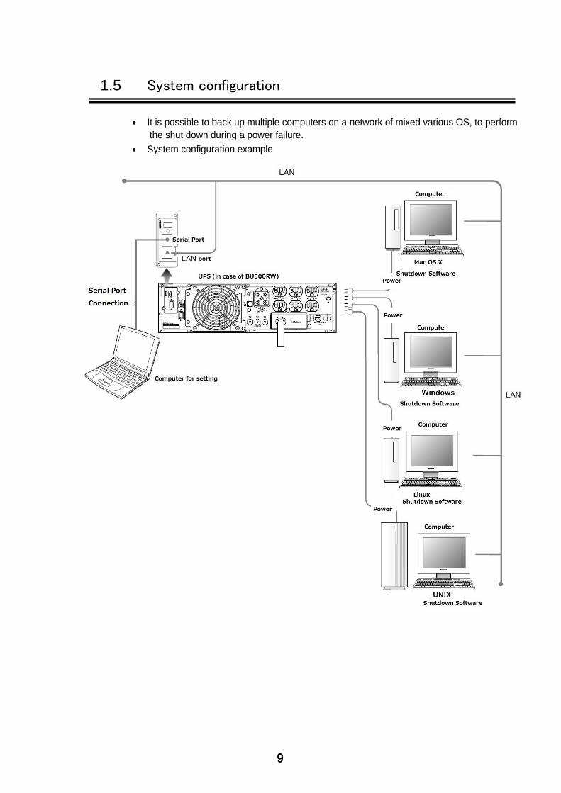
1.5 System configuration
It is possible to back up multiple computers on a network of mixed various OS, to perform
the shut down during a power failure.
System configuration example
10
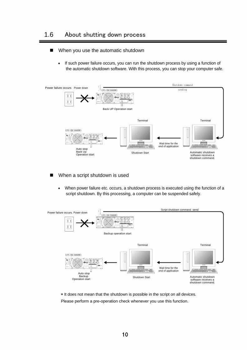
1.6 About shutting down process
When you use the automatic shutdown
If such power failure occurs, you can run the shutdown process by using a function of
the automatic shutdown software. With this process, you can stop your computer safe.
Power failure occurs Power down
UPS (BU300RW)
Shutdown command
sending
Back UP Operation start
Terminal Terminal
UPS (BU300RW)
Auto stop Back Up Operation start
Shutdown Start
Wait time for the end of application
Automatic shutdown software receives a
shutdown command.
When a script shutdown is used
When power failure etc. occurs, a shutdown process is executed using the function of a
script shutdown. By this processing, a computer can be suspended safely.
Power failure occurs. Power down
UPS (BU300RW)
Script shutdown command send
Backup operation start
Terminal Terminal
UPS (BU300RW)
Auto stop Backup
Operation start
Shutdown Start
Wait time for the end of application
Automatic shutdown software receives a
shutdown command.
* It does not mean that the shutdown is possible in the script on all devices.
Please perform a pre-operation check whenever you use this function.
11
2. Insertion of a SNMP/Web card
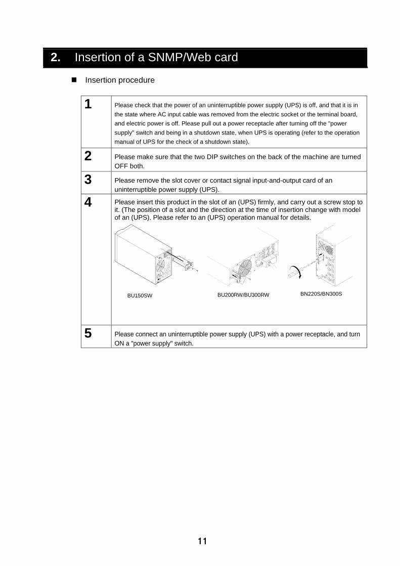
Insertion procedure
1 Please check that the power of an uninterruptible power supply (UPS) is off, and that it is in
the state where AC input cable was removed from the electric socket or the terminal board,
and electric power is off. Please pull out a power receptacle after turning off the "power
supply" switch and being in a shutdown state, when UPS is operating (refer to the operation
manual of UPS for the check of a shutdown state).
2 Please make sure that the two DIP switches on the back of the machine are turned
OFF both.
3 Please remove the slot cover or contact signal input-and-output card of an
uninterruptible power supply (UPS).
4 Please insert this product in the slot of an (UPS) firmly, and carry out a screw stop to it. (The position of a slot and the direction at the time of insertion change with model of an (UPS). Please refer to an (UPS) operation manual for details.
BU150SW BU200RW/BU300RW BN220S/BN300S
5 Please connect an uninterruptible power supply (UPS) with a power receptacle, and turn
ON a "power supply" switch.
12
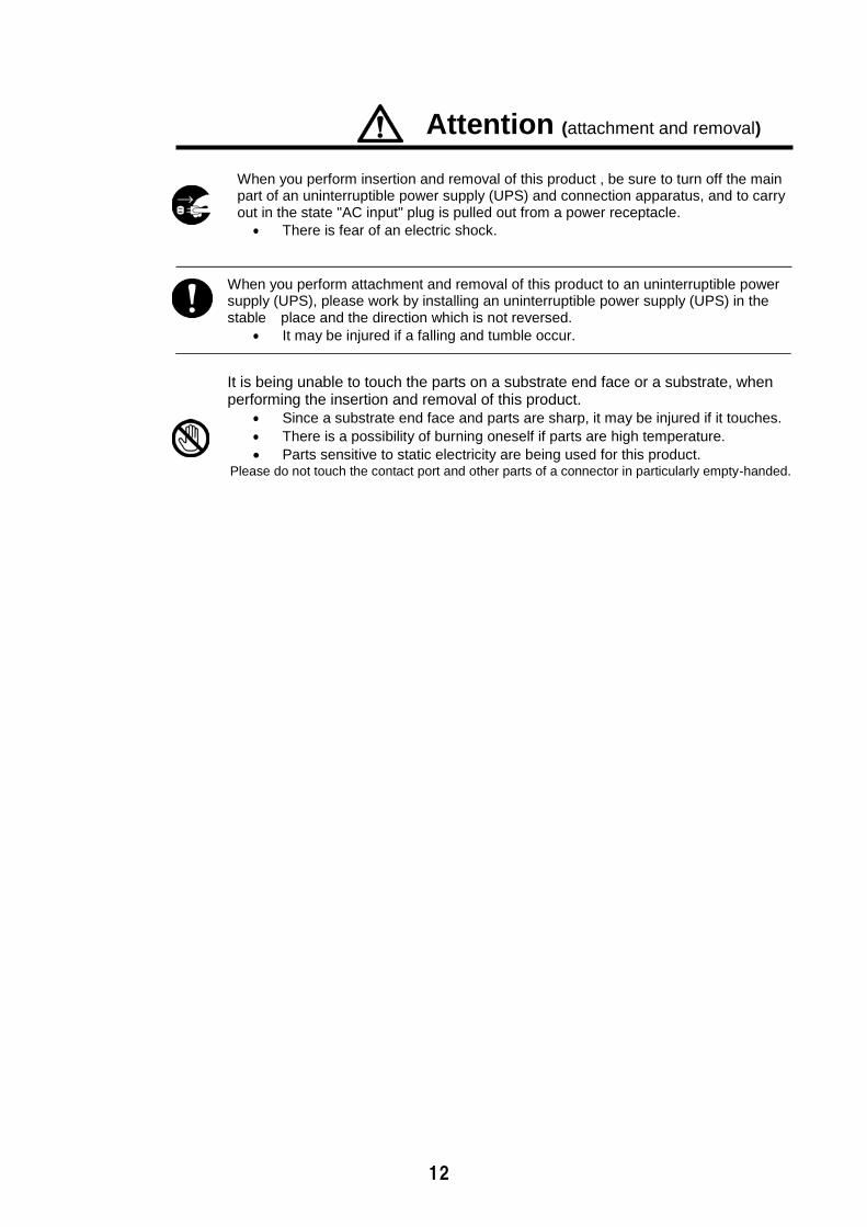
Attention (attachment and removal)
When you perform insertion and removal of this product , be sure to turn off the main part of an uninterruptible power supply (UPS) and connection apparatus, and to carry out in the state "AC input" plug is pulled out from a power receptacle.
There is fear of an electric shock.
When you perform attachment and removal of this product to an uninterruptible power supply (UPS), please work by installing an uninterruptible power supply (UPS) in the stable place and the direction which is not reversed.
It may be injured if a falling and tumble occur.
It is being unable to touch the parts on a substrate end face or a substrate, when performing the insertion and removal of this product.
Since a substrate end face and parts are sharp, it may be injured if it touches.
There is a possibility of burning oneself if parts are high temperature.
Parts sensitive to static electricity are being used for this product. Please do not touch the contact port and other parts of a connector in particularly empty-handed.
13
3. Network settings for SNMP / Web card
3.1 Basic information about the IP address setting
A setup for using this product on the target network is performed.
The fixed IP address of the initial value of this product is set as "192.168.2.150."
Please make a change of an fixed IP address from [SMNP-Web-Card Configuration Utility Main
menu] of a "method 1: via serial port “or a "method 2: via Telnet"
Settings through a Web browser can be useful after performing a set of network-related once.
Please refer to: "3.3 Network Configuration Method 2 :via Telnet " or " 3.2 Network
Configuration Method 1: via serial port "
This book explains Windows8.1 to an example. When you use other OS's,
please perform a setup for the following contents to reference.
14
3.2 Network Configuration Method 1: via serial port
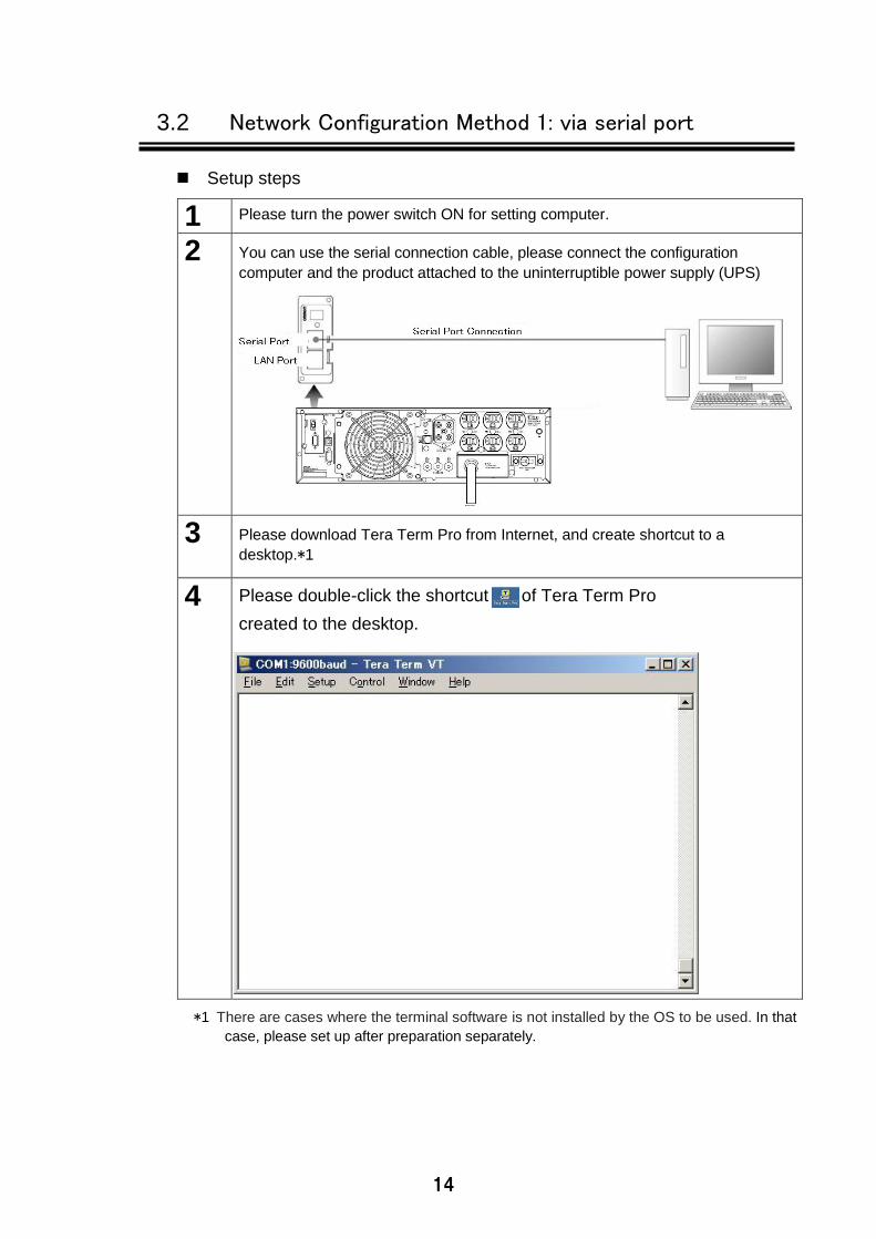
Setup steps
1 Please turn the power switch ON for setting computer.
2 You can use the serial connection cable, please connect the configuration
computer and the product attached to the uninterruptible power supply (UPS)
3 Please download Tera Term Pro from Internet, and create shortcut to a
desktop.*1
4 Please double-click the shortcut of Tera Term Pro
created to the desktop.
*1 There are cases where the terminal software is not installed by the OS to be used. In that
case, please set up after preparation separately.
15
ビット/秒 960 0
データビット 8
パリティ なし
ストップビット 1
フロー制御 なし
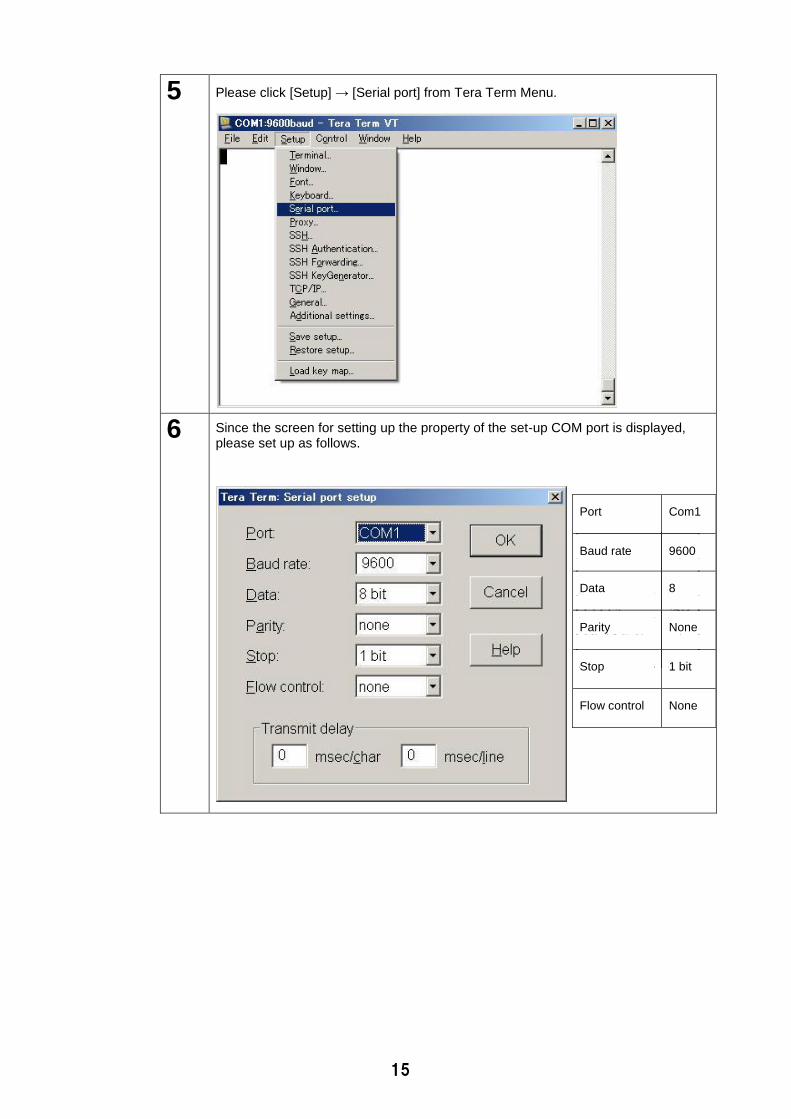
5 Please click [Setup] → [Serial port] from Tera Term Menu.
6 Since the screen for setting up the property of the set-up COM port is displayed, please set up as follows.
Port Com1
Baud rate 9600
Data 8
Parity None
Stop 1 bit
Flow control None
16
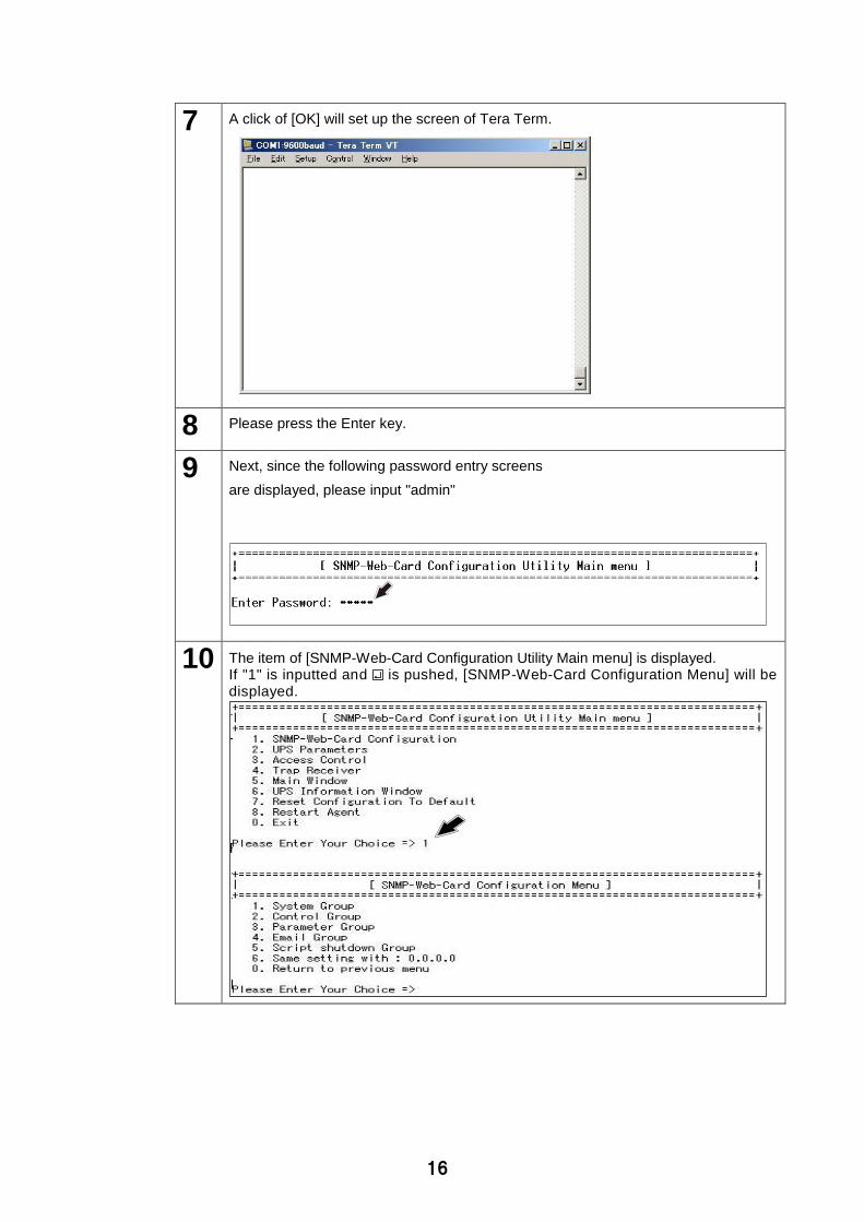
7 A click of [OK] will set up the screen of Tera Term.
8 Please press the Enter key.
9 Next, since the following password entry screens
are displayed, please input "admin"
10 The item of [SNMP-Web-Card Configuration Utility Main menu] is displayed. If "1" is inputted and is pushed, [SNMP-Web-Card Configuration Menu] will be displayed.
17
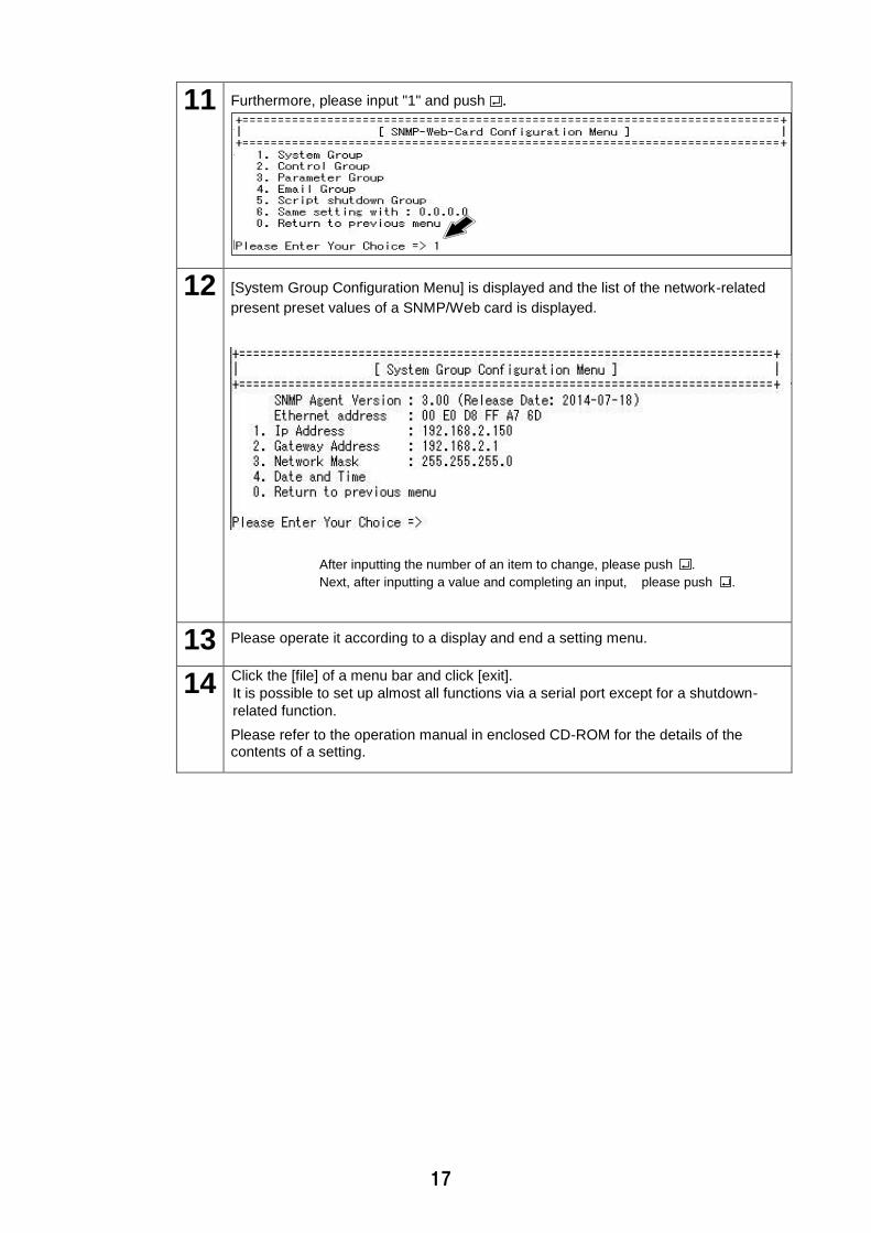
11 Furthermore, please input "1" and push .
12 [System Group Configuration Menu] is displayed and the list of the network-related
present preset values of a SNMP/Web card is displayed.
After inputting the number of an item to change, please push .
Next, after inputting a value and completing an input, please push .
13 Please operate it according to a display and end a setting menu.
14 Click the [file] of a menu bar and click [exit].
It is possible to set up almost all functions via a serial port except for a shutdown-
related function.
Please refer to the operation manual in enclosed CD-ROM for the details of the contents of a setting.
18
3.3 Network Configuration Method 2: via telnet
Please set up TCP/IP by computer for a setup as follows.
Setup steps of TCP/IP
1 Please choose the [control panel] → [network and Internet] after clicking [settings].
2 Next, click [network and a sharing center] → [Connections], then click [Properties].
When there is no[local-area connection], the LAN card (adapter)
is not installed. Please perform this operation after installing a LAN card (adapter).
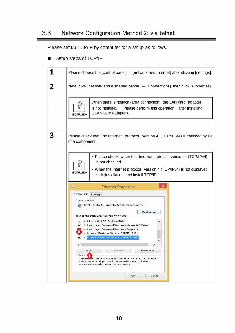
3 Please check that [the Internet protocol version 4] (TCP/IP V4) is checked by list
of a component.
Please check, when the Internet protocol version 4 (TCP/IPv4)
is not checked.
When the Internet protocol version 4 (TCP/IPv4) is not displayed,
click [installation] and install TCP/IP.
19
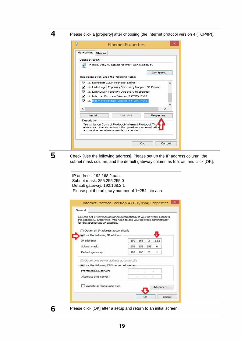
4 Please click a [property] after choosing [the Internet protocol version 4 (TCP/IP)].
5 Check [Use the following address]. Please set up the IP address column, the
subnet mask column, and the default gateway column as follows, and click [OK].
IP address: 192.168.2.aaa
Subnet mask: 255.255.255.0
Default gateway: 192.168.2.1
Please put the arbitrary number of 1~254 into aaa.
6 Please click [OK] after a setup and return to an initial screen.
20
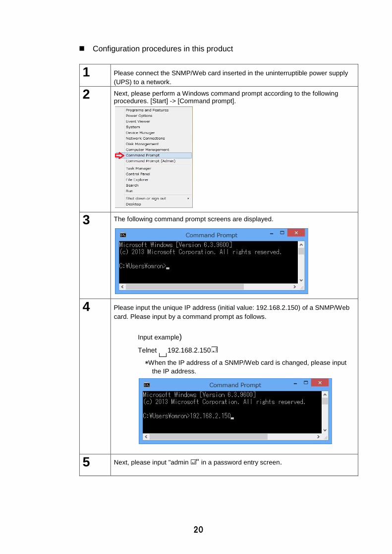
Configuration procedures in this product
1 Please connect the SNMP/Web card inserted in the uninterruptible power supply
(UPS) to a network.
2 Next, please perform a Windows command prompt according to the following procedures. [Start] -> [Command prompt].
3 The following command prompt screens are displayed.
4 Please input the unique IP address (initial value: 192.168.2.150) of a SNMP/Web
card. Please input by a command prompt as follows.
Input example)
Telnet 192.168.2.150
*When the IP address of a SNMP/Web card is changed, please input
the IP address.
5 Next, please input "admin " in a password entry screen.
21
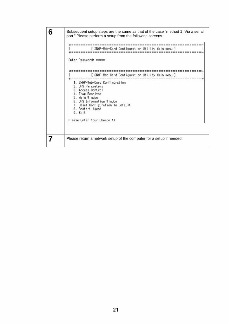
6 Subsequent setup steps are the same as that of the case "method 1: Via a serial port." Please perform a setup from the following screens.
7 Please return a network setup of the computer for a setup if needed.
22
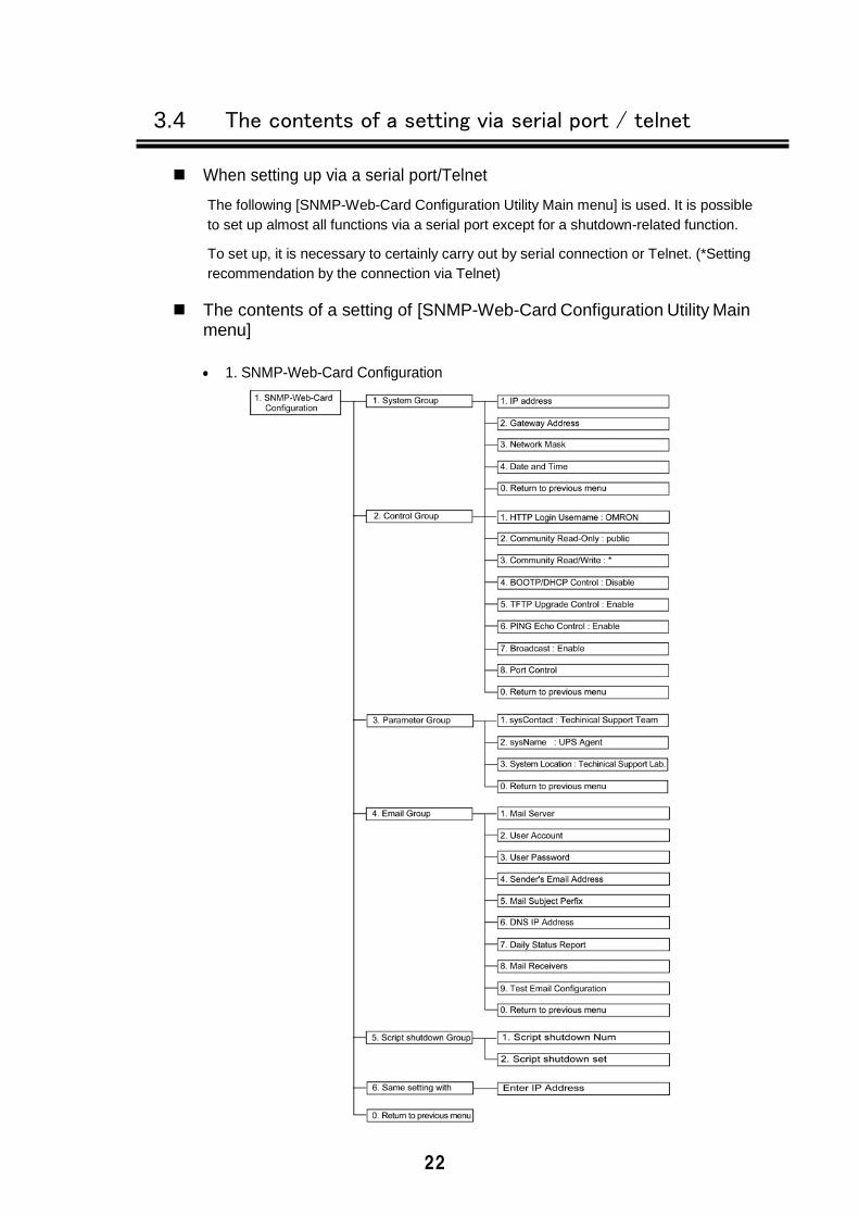
3.4 The contents of a setting via serial port / telnet
When setting up via a serial port/Telnet
The following [SNMP-Web-Card Configuration Utility Main menu] is used. It is possible
to set up almost all functions via a serial port except for a shutdown-related function.
To set up, it is necessary to certainly carry out by serial connection or Telnet. (*Setting
recommendation by the connection via Telnet)
The contents of a setting of [SNMP-Web-Card Configuration Utility Main menu]
1. SNMP-Web-Card Configuration
23
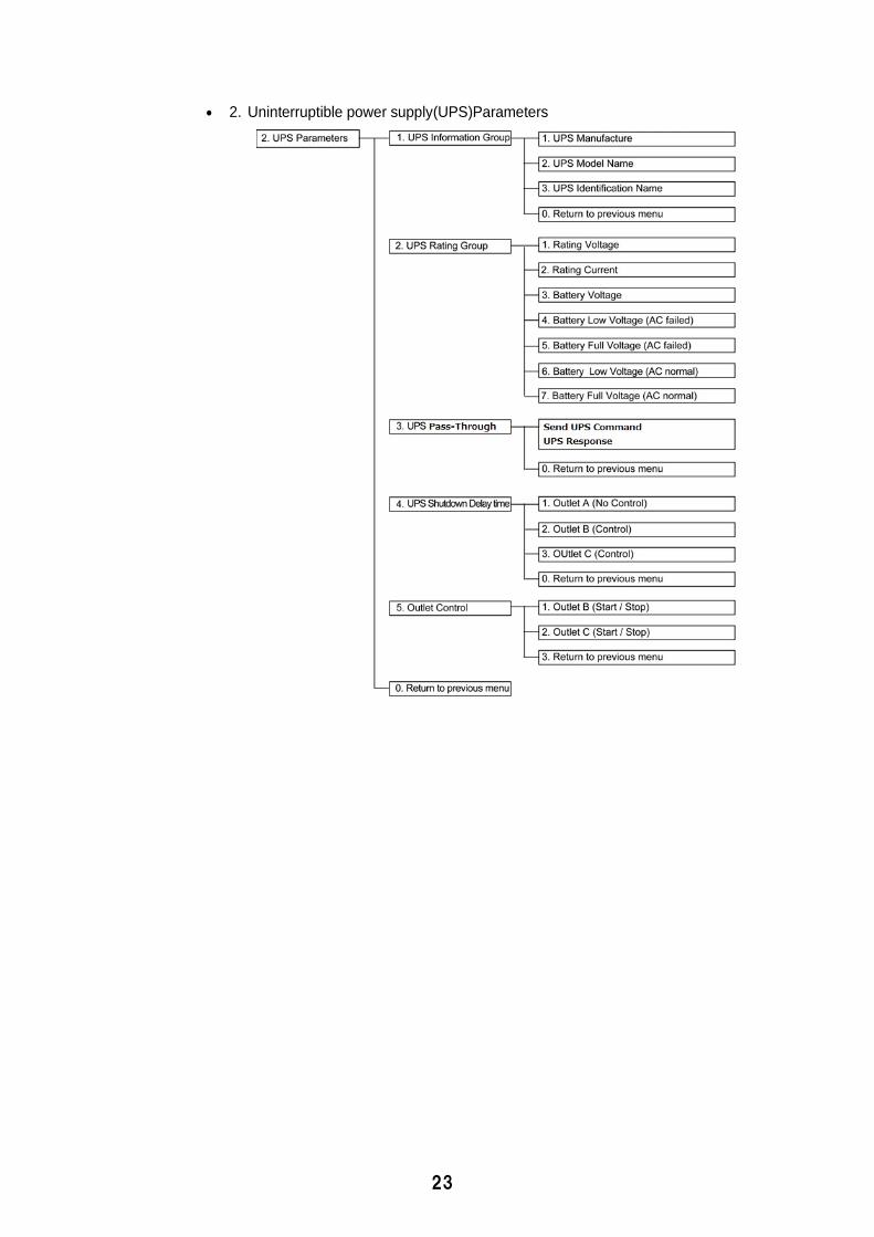
2. Uninterruptible power supply(UPS)Parameters
24
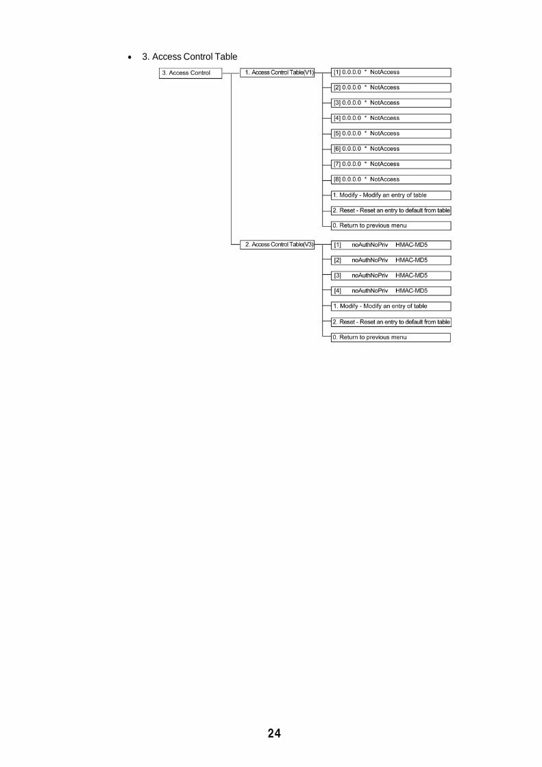
3. Access Control Table
25
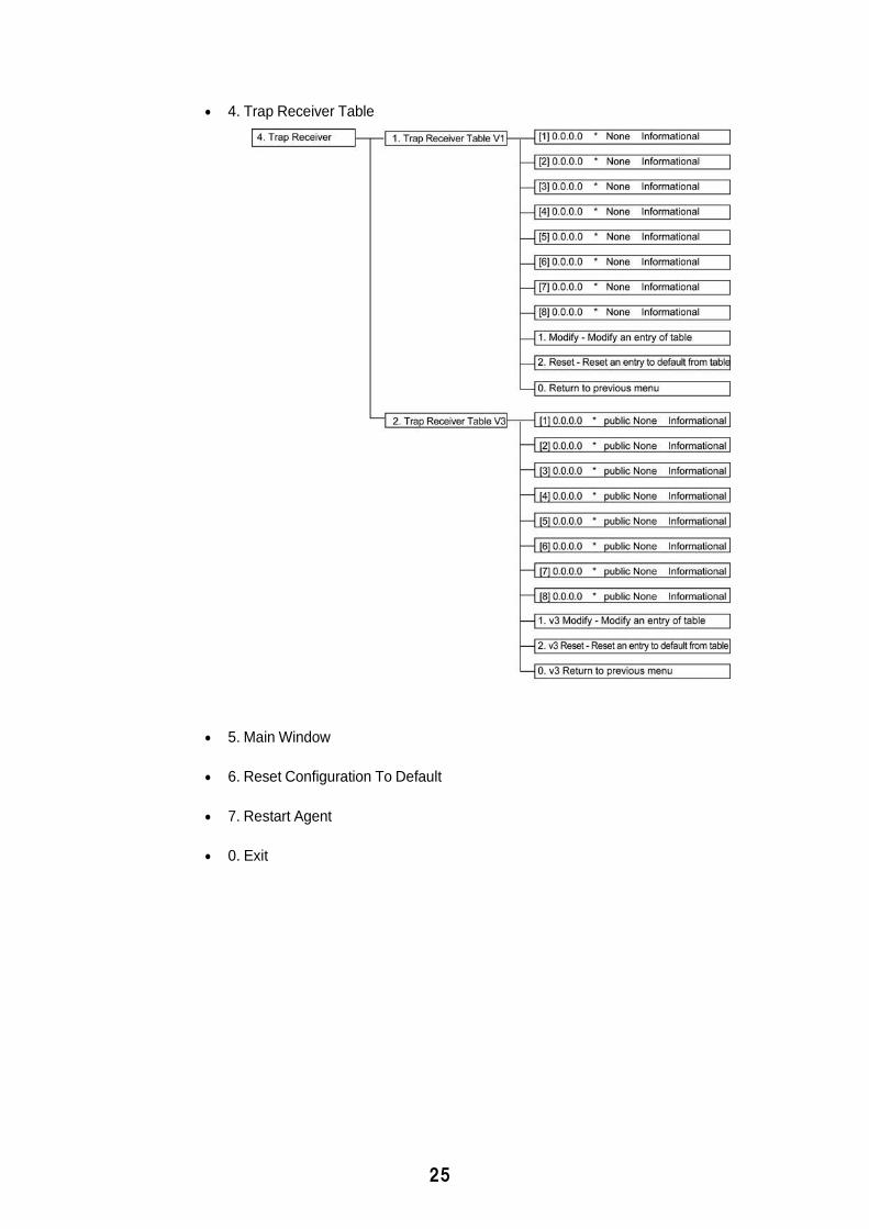
4. Trap Receiver Table
5. Main Window
6. Reset Configuration To Default
7. Restart Agent
0. Exit
26
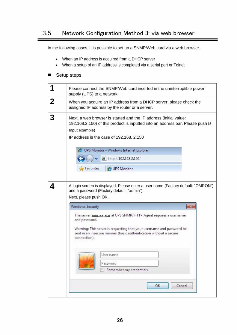
3.5 Network Configuration Method 3: via web browser
In the following cases, it is possible to set up a SNMP/Web card via a web browser.
When an IP address is acquired from a DHCP server
When a setup of an IP address is completed via a serial port or Telnet
Setup steps
1 Please connect the SNMP/Web card inserted in the uninterruptible power
supply (UPS) to a network.
2 When you acquire an IP address from a DHCP server, please check the
assigned IP address by the router or a server.
3 Next, a web browser is started and the IP address (initial value:
192.168.2.150) of this product is inputted into an address bar. Please push .
Input example)
IP address is the case of 192.168. 2.150
4 A login screen is displayed. Please enter a user name (Factory default: “OMRON”) and a password (Factory default: “admin”).
Next, please push OK.
27
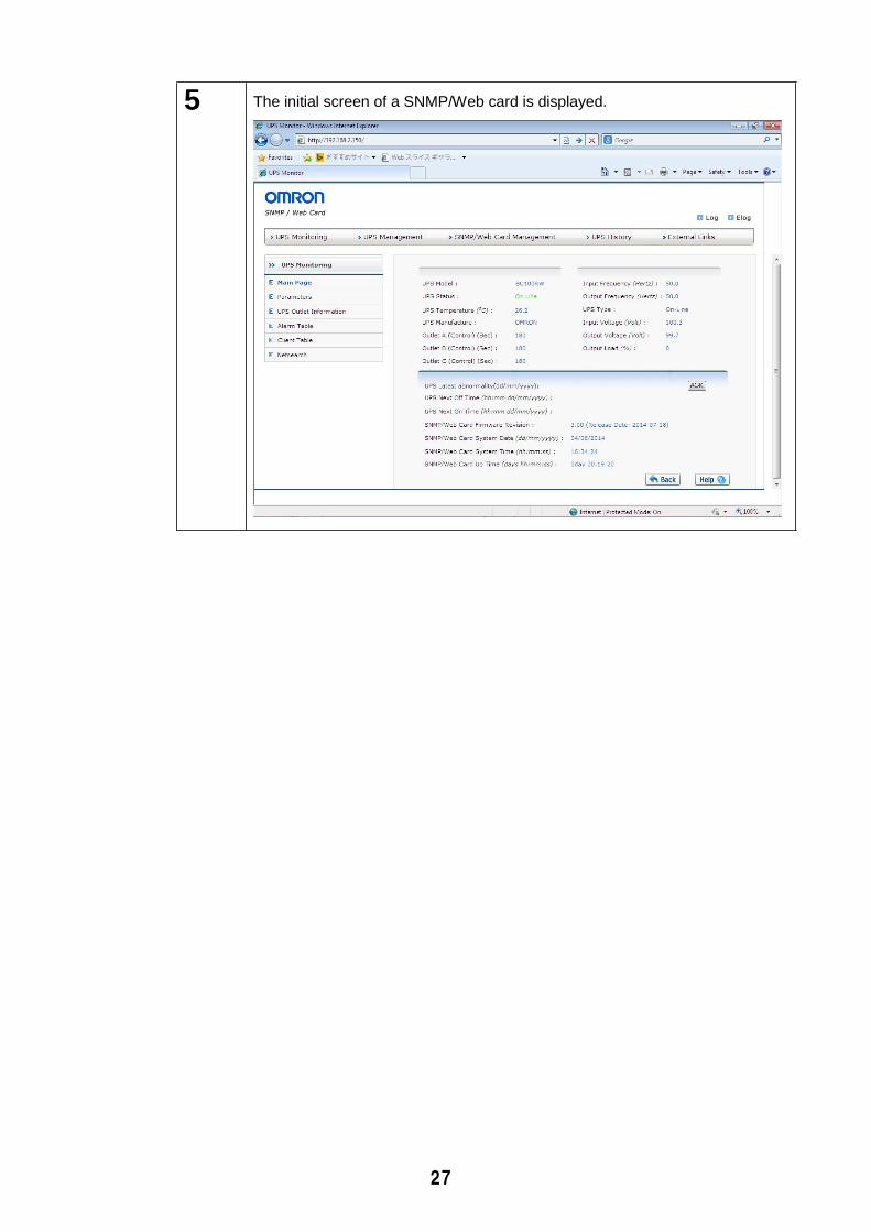
5 The initial screen of a SNMP/Web card is displayed.
4. Installation of automatic shutdown software
By installing PowerAct Pro Slave Agent of enclosed automatic shutdown software in this product, the automatic shutdown by the time of power failure or a schedule is possible. For installation instructions, please refer to the instruction manual of the automatic shutdown software.
Please check our homepage (http://www.omron.co.jp /ese/ups/) for the newest product information.
Each company name and each company product name are the trademarks or registered trademarks of each company Carrying out unapproved reproduction of a part or all of the contents of this operation manual is forbidden. It may change without a preliminary announcement about the contents of this operation