30
Station Automation COM600 3.5 SNTP OPC Server User's Manual

Station Automation COM600 3.5SNTP OPC Server User's Manual


Contents:
1. About this manual .................................................................................. 5
1.1. Copyrights ...................................................................................... 51.2. Trademarks .................................................................................... 51.3. General .......................................................................................... 51.4. Document conventions .................................................................. 61.5. Use of symbols .............................................................................. 71.6. Terminology .................................................................................... 71.7. Abbreviations ................................................................................. 91.8. Related documents ...................................................................... 101.9. Document revisions ..................................................................... 10
2. Introduction ........................................................................................... 11
2.1. Functional overview ..................................................................... 112.2. SNTP OPC Server features ......................................................... 11
3. Configuration ........................................................................................ 13
3.1. About this section ......................................................................... 133.2. Overview of configuration ............................................................ 133.3. Configuring SNTP OPC Server properties .................................. 203.4. Building object tree ...................................................................... 16
3.4.1. General about building object tree ................................ 163.4.2. Adding Gateway object ................................................. 173.4.3. Adding SNTP OPC Server object ................................. 173.4.4. Adding SNTP Virtual Subnetwork objects (optional) .... 173.4.5. Adding Virtual IED objects (optional) ........................... 183.4.6. Adding Logical Device objects (optional) ..................... 183.4.7. Adding Logical Node objects (optional) ....................... 183.4.8. Adding data objects (optional) ..................................... 19
3.5. Configuring objects ...................................................................... 193.5.1. Configuring object properties ........................................ 193.5.2. Configuring SNTP OPC Server properties .................... 203.5.3. Configuring data objects for Internal OPC Data ............ 21
3.5.3.1. General about configuring data objects forInternal OPC Data ...................................... 21
3.5.3.2. Integer status (INS) for OPC internal data .................................................................... 22
3.5.3.3. Controllable single point (SPC) for SNTPOPC internal data ....................................... 22
3.5.3.4. Single point status (SPS) for OPC internaldata ............................................................ 23
4. Operation ............................................................................................... 24
4.1. About this section ......................................................................... 24
3
Station Automation COM600 3.51MRS757277
SNTP OPC Server User's ManualIssued: 30.6.2011Version: A/30.6.2011

4.2. Activating COM600 with new configurations ............................... 244.3. SNTP OPC Server diagnostics .................................................... 244.4. Data object diagnostics ................................................................ 25
Index .............................................................................................................. 27
4
1MRS757277Station Automation COM600 3.5
SNTP OPC Server User's Manual

About this manual1.
Copyrights1.1.
The information in this document is subject to change without notice and should not beconstrued as a commitment by ABB Oy. ABB Oy assumes no responsibility for anyerrors that may appear in this document.
In no event shall ABB Oy be liable for direct, indirect, special, incidental, or consequentialdamages of any nature or kind arising from the use of this document, nor shall ABB Oybe liable for incidental or consequential damages arising from use of any software orhardware described in this document.
This document and parts thereof must not be reproduced or copied without written per-mission from ABB Oy, and the contents thereof must not be imparted to a third partynor used for any unauthorized purpose.
The software or hardware described in this document is furnished under a license andmay be used, copied, or disclosed only in accordance with the terms of such license.
© Copyright 2011 ABB. All rights reserved.
Trademarks1.2.
ABB is a registered trademark of ABB Group. All other brand or product names men-tioned in this document may be trademarks or registered trademarks of their respectiveholders.
General1.3.
This manual provides thorough information on the SNTP OPC Server and the centralconcepts related to it. You find instructions on how to configure SNTP OPC Serverrelated objects. The basic operation procedures are also discussed.
Information in this user’s manual is intended for application engineers who configurethe SNTP OPC Server.
This user’s manual is divided into following sections:
Introduction
This section gives an overview of the SNTP OPC Server and its features.
5
Station Automation COM600 3.51MRS757277
SNTP OPC Server User's Manual

Configuration
In this section you will find an overview of configuration. You are given instructionson how to configure SNTP OPC Server related objects and the model of a substationor system.
Operation
This section covers the basic operation procedures you can carry out when transferringor activating Station Automation COM600 (later referred to as COM600) with newconfigurations.
Document conventions1.4.
The following conventions are used for the presentation of material:• The words in names of screen elements (for example, the title in the title bar of a
window, the label for a field of a dialog box) are initially capitalized.• Capital letters are used for the name of a keyboard key if it is labeled on the keyboard.
For example, press the ENTER key.• Lowercase letters are used for the name of a keyboard key that is not labeled on the
keyboard. For example, the space bar, comma key, and so on.• Press CTRL+C indicates that you must hold down the CTRL key while pressing
the C key (to copy a selected object in this case).• Press ESC E C indicates that you press and release each key in sequence (to copy
a selected object in this case).• The names of push and toggle buttons are boldfaced. For example, click OK.• The names of menus and menu items are boldfaced. For example, the File menu.
• The following convention is used for menu operations: MenuName > Menu-Item > CascadedMenuItem. For example: select File > New > Type.
• The Start menu name always refers to the Start menu on the Windows taskbar.• System prompts/messages and user responses/input are shown in the Courier font.
For example, if you enter a value out of range, the following message is displayed:
Entered value is not valid. The value must be 0 - 30 .
• You can be asked to enter the string MIF349 in a field. The string is shown as followsin the procedure:
MIF349• Variables are shown using lowercase letters:
sequence name
6
1MRS757277Station Automation COM600 3.5
SNTP OPC Server User's Manual

Use of symbols1.5.
This publication includes warning, caution, and information icons that point out safety-related conditions or other important information. It also includes tip icons to point outuseful information to the reader. The corresponding icons should be interpreted as follows.
The electrical warning icon indicates the presence of a hazardwhich could result in electrical shock.
The warning icon indicates the presence of a hazard whichcould result in personal injury.
The caution icon indicates important information or warningrelated to the concept discussed in the text. It may indicatethe presence of a hazard which could result in corruption ofsoftware or damage to equipment or property.
The information icon alerts the reader to relevant facts andconditions.
The tip icon indicates advice on, for example, how to designyour project or how to use a certain function.
Terminology1.6.
The following is a list of terms associated with COM600 that you should be familiarwith. The list contains terms that are unique to ABB or have a usage or definition thatis different from standard industry usage.
DescriptionTerm
An abnormal state of a condition.Alarm
An OPC service for providing information about alarms andevents to OPC clients.
Alarms and Events; AE
An OPC service for providing information about process data toOPC clients.
Data Access; DA
7
Station Automation COM600 3.51MRS757277
SNTP OPC Server User's Manual

DescriptionTerm
Part of a logical node object representing specific information,for example, status, or measurement. From an object-orientedpoint of view, a data object is an instance of a class data object.DOs are normally used as transaction objects; that is, they aredata structures.
Data Object; DO
The data set is the content basis for reporting and logging. Thedata set contains references to the data and data attribute val-ues.
Data Set
A physical device that behaves as its own communication nodein the network, for example, protection relay.
Device
Change of process data or an OPC internal value. Normally, anevent consists of value, quality, and timestamp.
Event
A physical IEC 61850 device that behaves as its own commu-nication node in the IEC 61850 protocol.
Intelligent Electronic Device
Representation of a group of functions. Each function is definedas a logical node. A physical device consists of one or severalLDs.
Logical Device; LD
The smallest part of a function that exchanges data. An LN isan object defined by its data and methods.
Logical Node; LN
A communication protocol developed by Echelon.LON
A proprietary method of ABB on top of the standard LON pro-tocol.
LON Application Guideline forsubstation automation; LAG
Series of standards specifications aiming at open connectivityin industrial automation and the enterprise systems that supportindustry.
OPC
Representation of a connection to the data source within theOPC server. An OPC item is identified by a string <objectpath>:<property name>. Associated with each OPC item areValue, Quality, and Time Stamp.
OPC item
Named data item.Property
The report control block controls the reporting processes forevent data as they occur. The reporting process continues aslong as the communication is available.
Report Control Block
ABB proprietary communication protocol used in substationautomation.
SPA
Protection and/or Control Product supporting the SPA protocolversion 2.5 or earlier.
SPA device
XML-based description language for configurations of electricalsubstation IEDs. Defined in IEC 61850 standard.
Substation Configuration Lan-guage; SCL
8
1MRS757277Station Automation COM600 3.5
SNTP OPC Server User's Manual
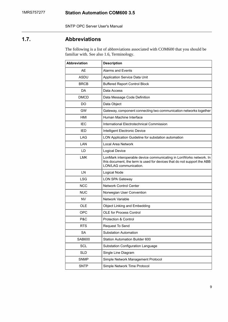
Abbreviations1.7.
The following is a list of abbreviations associated with COM600 that you should befamiliar with. See also 1.6, Terminology.
DescriptionAbbreviation
Alarms and EventsAE
Application Service Data UnitASDU
Buffered Report Control BlockBRCB
Data AccessDA
Data Message Code DefinitionDMCD
Data ObjectDO
Gateway, component connecting two communication networks togetherGW
Human Machine InterfaceHMI
International Electrotechnical CommissionIEC
Intelligent Electronic DeviceIED
LON Application Guideline for substation automationLAG
Local Area NetworkLAN
Logical DeviceLD
LonMark interoperable device communicating in LonWorks network. Inthis document, the term is used for devices that do not support the ABBLON/LAG communication.
LMK
Logical NodeLN
LON SPA GatewayLSG
Network Control CenterNCC
Norwegian User ConventionNUC
Network VariableNV
Object Linking and EmbeddingOLE
OLE for Process ControlOPC
Protection & ControlP&C
Request To SendRTS
Substation AutomationSA
Station Automation Builder 600SAB600
Substation Configuration LanguageSCL
Single Line DiagramSLD
Simple Network Management ProtocolSNMP
Simple Network Time ProtocolSNTP
9
Station Automation COM600 3.51MRS757277
SNTP OPC Server User's Manual

DescriptionAbbreviation
Simple Object Access ProtocolSOAP
Report Control BlockRCB
Unbuffered Report Control BlockURCB
eXtended Markup LanguageXML
Related documents1.8.
MRS numberName of the manual
1MRS756125COM600 User's manual
Document revisions1.9.
HistoryProduct revisionDocument version/date
Document created3.5A/30.6.2011
10
1MRS757277Station Automation COM600 3.5
SNTP OPC Server User's Manual

Introduction2.
Functional overview2.1.
The SNTP OPC Server includes an SNTP server and a client. The SNTP server enablesSNTP clients (for example, IEDs) to synchronize their time with the time of COM600.The SNTP client of the SNTP OPC Server enables the synchronization of COM600 froman external SNTP server (for example, GPS Clock device). The SNTP server and clientfunctionality can be configured and activated separately. The SNTP OPC Server providesdiagnostic information about the synchronization status, that can be used, for example,in the COM600 HMI, or forwarded to a remote system via a slave protocol.
IEC 61850 OPC Server also includes the SNTP server andclient functionality. The SNTP server and client should beconfigured either in the IEC 61850 OPC Server or in the SNTPOPC Server, but not in both.
SNTP_overview.png
Figure 2.1-1 System overview
1. Network time source2. COM600 with SNTP OPC Server3. Station Automation Builder 600 (SAB600)4. Protection and control devices with SNTP client
SNTP OPC Server features2.2.
The SNTP OPC Server supports the following features:• OPC Data Access Server v. 1.0/2.0
11
Station Automation COM600 3.51MRS757277
SNTP OPC Server User's Manual

• OPC Alarms and Events server v. 1.10• SNTP client and server for time synchronization
12
1MRS757277Station Automation COM600 3.5
SNTP OPC Server User's Manual
Configuration3.
About this section3.1.
This section guides you in the configuration tasks required before you can start usingthe SNTP OPC Server. For information on the IEC 61850 data modeling, refer toCOM600 User's Manual.
Start Station Automation Builder 600 (later referred to as SAB600) to open a project.You can also open and name a new project.
1. Select File > Open/Manage Project....2. In the Open/Manage Project dialog, select the required location for the project:
• Projects on my computer• Projects on network
3. Select New Project on the left.• Enter a Project Name. The Description is optional.
4. Click Create.5. Click Open Project.
Overview of configuration3.2.
Before you can start using the SNTP OPC Server, you need to build and configure anobject tree in SAB600 to define the Communication structure within the Gateway object.
The possible objects are:• Gateway• SNTP OPC Server• SNTP Virtual Subnetwork• SNTP Virtual IED• Logical Device objects• Logical Node objects• Data objects
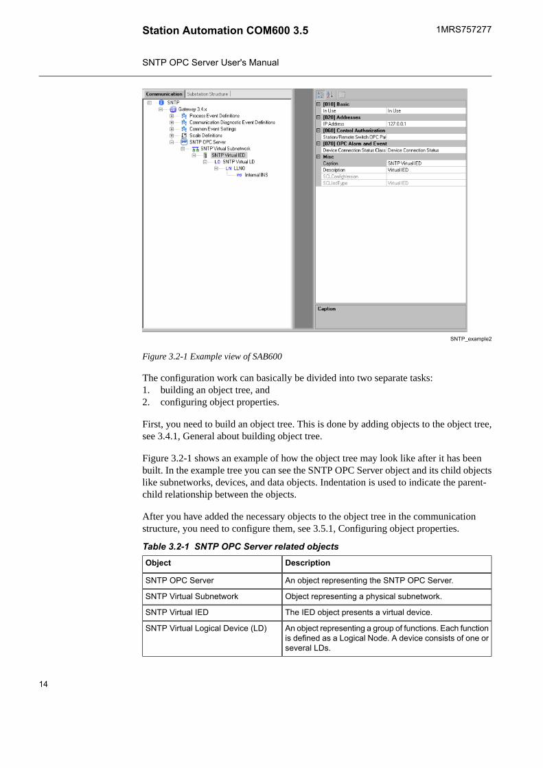
Figure 3.2-1 shows an example view of SAB600 including an object tree in the commu-nication structure on the left and Object Properties window displaying the object propertieson the right.
When configuring OPC servers the following characters cannotbe used in object names: \ ` ' ' #
13
Station Automation COM600 3.51MRS757277
SNTP OPC Server User's Manual
SNTP_example2
Figure 3.2-1 Example view of SAB600
The configuration work can basically be divided into two separate tasks:1. building an object tree, and2. configuring object properties.
First, you need to build an object tree. This is done by adding objects to the object tree,see 3.4.1, General about building object tree.
Figure 3.2-1 shows an example of how the object tree may look like after it has beenbuilt. In the example tree you can see the SNTP OPC Server object and its child objectslike subnetworks, devices, and data objects. Indentation is used to indicate the parent-child relationship between the objects.
After you have added the necessary objects to the object tree in the communicationstructure, you need to configure them, see 3.5.1, Configuring object properties.
Table 3.2-1 SNTP OPC Server related objectsDescriptionObject
An object representing the SNTP OPC Server.SNTP OPC Server
Object representing a physical subnetwork.SNTP Virtual Subnetwork
The IED object presents a virtual device.SNTP Virtual IED
An object representing a group of functions. Each functionis defined as a Logical Node. A device consists of one orseveral LDs.
SNTP Virtual Logical Device (LD)
14
1MRS757277Station Automation COM600 3.5
SNTP OPC Server User's Manual

DescriptionObject
An object defined by its data and methods. LN is thesmallest part of a function that exchanges data.
Logical Node (LN)
Data object is an instance of one of the IEC 61850 DataObject Classes such as Single point status and MeasuredValue. Depending on the class, each data object has aset of attributes for monitoring and controlling the object,e.g. value, quality, and control.
Data Object (DO)
Configuring SNTP OPC Server properties3.3.
Table 3.3-1 lists the configurable SNTP OPC Server properties and value ranges forthem. The actual configuration by using SAB600 is performed as described in3.5.1, Configuring object properties.
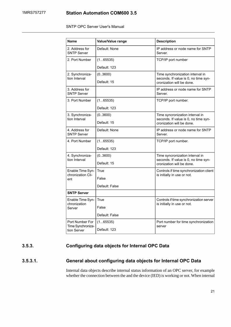
Table 3.3-1 SNTP OPC Server propertiesDescriptionValue/Value rangeName
SNTP Client
IP address or node name for SNTPServer (Primary)
1. Address forSNTP Server
TCP/IP port number(1..65535)
Default: 123
1. Port Number
Time syncronization interval inseconds. If value is 0, no time syn-cronization will be done.
(0..3600)
Default: 15
1. Synchroniza-tion Interval
IP address or node name for SNTPServer.
Default: None2. Address forSNTP Server
TCP/IP port number(1...65535)
Default: 123
2. Port Number
Time synchronization interval inseconds. If value is 0, no time syn-cronization will be done.
(0..3600)
Default: 15
2. Synchroniza-tion Interval
IP address or node name for SNTPServer.
3. Address forSNTP Server
TCP/IP port number.(1...65535)
Default: 123
3. Port Number
Time syncronization interval inseconds. If value is 0, no time syn-cronization will be done.
(0..3600)
Default: 15
3. Synchroniza-tion Interval
IP address or node name for SNTPServer.
Default: None4. Address forSNTP Server
15
Station Automation COM600 3.51MRS757277
SNTP OPC Server User's Manual

DescriptionValue/Value rangeName
TCP/IP port number.(1...65535)
Default: 123
4. Port Number
Time syncronization interval inseconds. If value is 0, no time syn-cronization will be done.
(0..3600)
Default: 15
4. Synchroniza-tion Interval
Controls if time synchronization clientis initially in use or not.
True
False
Default: False
Enable Time Syn-chronization Cli-ent
SNTP Server
Controls if time synchronization serveris initially in use or not.
True
False
Default: False
Enable Time Syn-chronizationServer
Port number for time synchronizationserver
(1...65535)
Default: 123
Port Number ForTime Synchroniza-tion Server
Building object tree3.4.
General about building object tree3.4.1.
The object tree is built in the Communication structure of SAB600, see Figure 3.2-1. Itis built by adding objects in a logical order starting from the Gateway.
You have several possible ways to add objects to the object tree in the Communicationstructure:• You can right-click the object to which you want to add a child object. Then select
New > Object type group > Object name, for example New > Time Synchroniz-ation > SNTP OPC Server.
• You can right-click the object type and select New > New. A New Object windowappears. Select the object type you want to add and click OK or double-click it.
• You can copy the object.
Add the objects in the following order:1. Gateway2. SNTP OPC Server3. SNTP Virtual Subnetwork (optional)4. SNTP Virtual IED (optional)5. Logical Device objects (optional)6. Logical Node objects (optional)7. Data objects (optional)
16
1MRS757277Station Automation COM600 3.5
SNTP OPC Server User's Manual

Virtual Subnetwork and objects below it are only needed fordiagnostic purpose.
Adding Gateway object3.4.2.
To start building the object tree, add a Gateway object in the Communication structureby selecting the project name, right-click it and select New > Communication > Gate-way.
Adding SNTP OPC Server object3.4.3.
After the Gateway object has successfully been added, you can continue building theobject tree by adding an SNTP OPC Server object.
To add an SNTP OPC Server object:1. Select the Gateway object in the communication structure and right-click it.2. Select New > Time Synchronization > SNTP OPC Server.
By using the SCL Import function, it is possible to import an entire server’s or individualdevice's configurations without having to insert them manually. To open the SCL Importfunction, right-click the desired object, and select SCL Import.
For more information about the SCL Import function, see COM600 User's Manual.
Adding SNTP Virtual Subnetwork objects (optional)3.4.4.
Virtual Subnetwork and the objects below it are only used toprovide diagnostic status information about the SNTP serveror client for the COM600 HMI or other applications.
After the server object has been successfully added, you can continue building the objecttree by adding subnetwork objects.
To add SNTP Virtual subnetwork object:1. Select SNTP OPC Server object.2. Right-click the SNTP OPC Server object.3. Select New > New or New > Virtual > SNTP Virtual Subnetwork.
17
Station Automation COM600 3.51MRS757277
SNTP OPC Server User's Manual

Adding Virtual IED objects (optional)3.4.5.
After adding a subnetwork you can add virtual device objects.
To add a Virtual Device object:1. Select a Subnetwork object.2. Right-click on the Subnetwork object and select New > New or New > Virtual >
SNTP Virtual IED.
With SCL import function, you can import new objects with configurations from anexisting file. Right-click the device and select SCL Import from the shortcut menu.
To import a new configuration file:1. Click Select File.2. Browse to a new configuration file from the appearing dialog.3. Select the file and click Open.4. Select the device to import from the drop-down list. You can preview the configur-
ation on the right.5. Click Import.
The new preconfigured objects appear in the object tree. If the configuration file is large,the import may take time. To import a configuration file for a different device, right-click the device, select SCL Import again and repeat the steps above.
For more information about the SCL Import function, see COM600 User's Manual.
Adding Logical Device objects (optional)3.4.6.
Virtual subnetwork and the objects below it are only used for diagnostic purpose. Oncea Virtual IED object is added, two data objects representing Server Status and ClientStatus are pre-populated and included in the object tree.
To add a Logical Device object:1. Select an SNTP Virtual IED object and right-click it.2. Select New > New or New > Communication > SNTP Virtual LD.
Each SNTP IED must have at least one Logical Device objectas a child object.
Adding Logical Node objects (optional)3.4.7.
To add a Logical Node:1. Select a Logical Device object and right-click it.2. Add a Logical Node object.3. Rename the new object. The names of the Logical Node objects have to be unique.
18
1MRS757277Station Automation COM600 3.5
SNTP OPC Server User's Manual

You should have only one Logical Node 0 (LLN0) as a childobject to a Logical Device object.
Adding data objects (optional)3.4.8.
To add a data object:1. Select a Logical Node object and right-click it.2. Add a data object.3. Rename the new object. The names of the data objects have to be unique. However,
you can have a data object with same name under a different Logical Node.
Configuring objects3.5.
Configuring object properties3.5.1.
After the objects have been added, you must configure the object properties.
To configure an object:1. Select an object in the object tree of the Communication structure.2. The object properties appear now in the Object Properties window, see Figure 3.5.1-
1. You can see the selected object on the left and the available properties on theright.
3. Select the property you want to configure. Depending on the property value type,configuring is always done either by• selecting a predefined value from a drop-down combo box, or• entering a text string or a numerical value in a text field.
19
Station Automation COM600 3.51MRS757277
SNTP OPC Server User's Manual

SNTP_OPC_Server_Object_Properties.PNG
Figure 3.5.1-1 Example of object properties
The available properties for different objects are listed in the following subsections.
Configuring SNTP OPC Server properties3.5.2.
Table 3.3-1 lists the configurable SNTP OPC Server properties and value ranges forthem. The actual configuration by using SAB600 is performed as described in3.5.1, Configuring object properties.
Table 3.5.2-1 SNTP OPC Server propertiesDescriptionValue/Value rangeName
SNTP Client
IP address or node name for SNTPServer (Primary)
1. Address forSNTP Server
TCP/IP port number(1..65535)
Default: 123
1. Port Number
Time syncronization interval inseconds. If value is 0, no time syn-cronization will be done.
(0..3600)
Default: 15
1. Synchroniza-tion Interval
20
1MRS757277Station Automation COM600 3.5
SNTP OPC Server User's Manual
DescriptionValue/Value rangeName
IP address or node name for SNTPServer.
Default: None2. Address forSNTP Server
TCP/IP port number(1...65535)
Default: 123
2. Port Number
Time synchronization interval inseconds. If value is 0, no time syn-cronization will be done.
(0..3600)
Default: 15
2. Synchroniza-tion Interval
IP address or node name for SNTPServer.
3. Address forSNTP Server
TCP/IP port number.(1...65535)
Default: 123
3. Port Number
Time syncronization interval inseconds. If value is 0, no time syn-cronization will be done.
(0..3600)
Default: 15
3. Synchroniza-tion Interval
IP address or node name for SNTPServer.
Default: None4. Address forSNTP Server
TCP/IP port number.(1...65535)
Default: 123
4. Port Number
Time syncronization interval inseconds. If value is 0, no time syn-cronization will be done.
(0..3600)
Default: 15
4. Synchroniza-tion Interval
Controls if time synchronization clientis initially in use or not.
True
False
Default: False
Enable Time Syn-chronization Cli-ent
SNTP Server
Controls if time synchronization serveris initially in use or not.
True
False
Default: False
Enable Time Syn-chronizationServer
Port number for time synchronizationserver
(1...65535)
Default: 123
Port Number ForTime Synchroniza-tion Server
Configuring data objects for Internal OPC Data3.5.3.
General about configuring data objects for Internal OPC Data3.5.3.1.
Internal data objects describe internal status information of an OPC server, for examplewhether the connection between the and the device (IED) is working or not. When internal
21
Station Automation COM600 3.51MRS757277
SNTP OPC Server User's Manual

information of an OPC server needs to be transferred, that is information that does notoriginate from a device, to an OPC Client, virtual data objects must be created.
The SNTP OPC Server supports three internal data object types that provide statusinformation:• 3.5.3.2, Integer status (INS) for OPC internal data• 3.5.3.3, Controllable single point (SPC) for SNTP OPC internal data• 3.5.3.4, Single point status (SPS) for OPC internal data
Integer status (INS) for OPC internal data3.5.3.2.
Table 3.5.3.2-1 Configurable INS (for OPC internal data) properties for OPC ServersDescriptionValue or Value range/ DefaultProperty/Para-
meter
Basic
Common data class according to IEC61850
INSCommon DataClass
Addresses
Item tag path for the internal statusinformation. The internal server tags thatcan be used are located in the Attributesnodes that are located under the root, line,and IED nodes. When an attribute tag isreferred to in the internal item definitionsbelow, it is possible to use either the wholetag path or just the path relative to the IED(the internal tags are configured per IED);for example, Attributes\Diagnostic coun-ters\Transmitted data messages. Whenthe whole path is used, it must be pre-ceded by a slash (/) character, forexample, /Channel Name\Attributes\Dia-gnostic counters\Transmitted data mes-sages.
Default: NoneItem Tag Path
Controllable single point (SPC) for SNTP OPC internal data3.5.3.3.
Table 3.5.3.3-1 Configurable SPC (for OPC internal data) properties for OPC ServersDescriptionValue or Value range/ DefaultProperty/Para-
meter
Basic
Common data class according to IEC61850.
SPCCommon DataClass
Addresses
22
1MRS757277Station Automation COM600 3.5
SNTP OPC Server User's Manual

DescriptionValue or Value range/ DefaultProperty/Para-meter
Item tag path for the internal statusinformation. The internal server tags thatcan be used are located in the Attributesnodes that are located under the root, lineand IED nodes. When an attribute tag isreferred to in the internal item definitionsbelow it is possible to use either the wholetag path or just the path relative to the IED(the internal tags are configured per IED)e.g. Attributes\Diagnostic counters\Trans-mitted data messages. When the wholepath is used it must be preceded by aslash (/) character e.g. /ChannelName\Attributes\Diagnostic counters\Trans-mitted data messages.
Default: NoneItem Tag Path
Single point status (SPS) for OPC internal data3.5.3.4.
Table 3.5.3.4-1 Configurable SPS (for OPC internal data) properties for OPC serversDescriptionValue or Value range/ DefaultProperty/Para-
meter
Basic
Common data class according to IEC61850
SPSCommon DataClass
Addresses
Item tag path for the internal statusinformation. The internal server tags thatcan be used are located in the Attributesnodes that are located under the root, line,and IED nodes. When an attribute tag isreferred to in the internal item definitionsbelow, it is possible to use either the wholetag path or just the path relative to the IED(the internal tags are configured per IED);e.g. Attributes\Diagnostic counters\Trans-mitted data messages. When the wholepath is used, it must be preceded by aslash (/) character, e.g. /ChannelName\Attributes\Diagnostic counters\Trans-mitted data messages.
Client Status:
Attributes\TimeSync\Timesyncclient\In use
Attributes\TimeSync\Timesyncclient\Timesync status
Server Status:
Attributes\TimeSync\Timesyncserver\In use
Attributes\TimeSync\Timesyncserver\Timesync status
Item Tag Path
23
Station Automation COM600 3.51MRS757277
SNTP OPC Server User's Manual

Operation4.
About this section4.1.
This section describes the basic operation procedures you can carry out after the beenconfigured.
After this, you can, for example, monitor and control the condition of connections innetwork. This is done by using the Online diagnostics function in SAB600.
Activating COM600 with new configurations4.2.
For information about activating COM600 with new configuration, see COM600 User’sManual.
SNTP OPC Server diagnostics4.3.
To view the SNTP OPC Server diagnostics, right-click the SNTP OPC Server objectand select Diagnostic AE Client, see Figure 4.3-1.
SNTP_OPC_Server_Online_Diagnostics.png
Figure 4.3-1 SNTP OPC Server diagnostics
You have the following alternatives:• to view version information
24
1MRS757277Station Automation COM600 3.5
SNTP OPC Server User's Manual

• to reset the SNTP OPC Server• to view the event log file• to clear the log file
Ext_Event_log_file.png
Figure 4.3-2 Event log file
Diagnostic AE Client
Diagnostic events can be monitored and controlled using the Diagnostic AE Clientfunction. Click Refresh to update the status information. To be able to receive eventsfrom a certain device, diagnostic events must be enabled for this respective device.
To enable diagnostic events:1. Right-click the device.2. Select Diagnostic AE Client.
Data object diagnostics4.4.
For information on data object diagnostics, refer to COM600 User’s Manual.
25
Station Automation COM600 3.51MRS757277
SNTP OPC Server User's Manual

26

Index
Aadding
Data object ..................................................................................................... 19Gateway object ............................................................................................... 17Logical device ................................................................................................ 18Logical node ................................................................................................... 18OPC Server object .......................................................................................... 17
Cconfiguration
object properties ............................................................................................. 19Controllable single point (SPC)
properties ....................................................................................................... 22
DData object
adding ........................................................................................................... 19data object
diagnostics ..................................................................................................... 25diagnostics
server ............................................................................................................ 24
GGateway object
adding ........................................................................................................... 17
IInteger status (INS)
properties ....................................................................................................... 22
LLogical device
adding ........................................................................................................... 18Logical node
adding ........................................................................................................... 18
27
Station Automation COM600 3.51MRS757277
SNTP OPC Server User's Manual

Oobject properties
configuration .................................................................................................. 19object tree
building .......................................................................................................... 16OPC Server
properties ................................................................................................. 15, 20OPC Server object
adding ........................................................................................................... 17
Pproperties
Controllable single point (SPC) ........................................................................ 22Integer status (INS) ......................................................................................... 22OPC Server .............................................................................................. 15, 20Single point status (SPS) ................................................................................ 23
Sserver
diagnostics ..................................................................................................... 24Single point status (SPS)
properties ....................................................................................................... 23SNTP
subnetwork .................................................................................................... 17SNTP Virtual
IED object ...................................................................................................... 18subnetwork
SNTP ............................................................................................................. 17
28
1MRS757277Station Automation COM600 3.5
SNTP OPC Server User's Manual


Contact us
1MR
S75
7277
A/3
0.6.
2011
© C
opyr
ight
201
0 A
BB
. All
right
s re
serv
ed.
ABB OyDistribution AutomationP.O. Box 699FI-65101 VAASA, FINLANDTel. +358 10 22 11Fax. +358 10 224 1094
ABB Inc.Distribution Automation655 Century PointLake Mary, FL 32746, USATel: +1 407 732 2000Fax: +1 407 732 2335
www.abb.com/substationautomation


