Page 1
SoC Development Kit Setup Instructions (Windows 7)
1. PC setup
The following software must be pre-installed on the target machine:
1) Quartus II 13.0 (or newer) or the Quartus II 13.0 (or newer) standalone programmer
2) SOC EDS 13.0 (or newer)
The installation packages for the above software can be downloaded from the Altera web site.
3) PuTTY
This is a freeware terminal emulation program that can be downloaded at:
ftp://ftp.chiark.greenend.org.uk/users/sgtatham/putty-latest/x86/putty.exe
You can use another terminal emulation program if you have a preference.
4) UART to USB drivers
The device driver for the UART to USB converter on the Cyclone V SoC development board must be
downloaded and installed before use.Rev C boards feature a FDTI UART to USB converter. The driver for
this device can be downloaded at:
http://www.ftdichip.com/Drivers/CDM/CDM%202.08.28%20WHQL%20Certified.zip.
Page 2
SoC Development Kit Setup Revision C
. Page 2
2. Development Board Setup
A picture of the Cyclone V SoC development kit can be found below. All the relevant setup elements are
highlighted and ideally should be already set to a good configuration.
In the instructions below, the board orientation is assumed to be the same as in the above picture.
1) Set the JTAG enable switches as down-down-up-up from left to right.
This puts both the HPS and the FPGA portions of the SoC device on the JTAG chain.
2) Set the JTAG sel and HPS JTAG sel jumpers as both closed (on).
This redirects the HPS and FPGA JTAG chains to the USB Blaster II on board.
3) Set the CSEL and BSEL jumpers as right (2-3), right, right, right, left (1-2).
This forces the SoC device to boot from SD/MMC card.
4) Insert the SD card programmed with the demo image in the SD card slot of the development kit.
Instructions for programming the card can be found in section 4.
5) Connect the USB Blaster II cable to the bottom USB port of the development kit.
This is a USB A to Mini-B cable.
6) Connect the USB to UART cable to the right USB port of the development kit.
This is a USB A to Mini-B cable.
SD CARD slot
JTAG switches
swiswitches
JTAG jumpers
swiswitches
CSEL/BSEL jumpers
swiswitches
USB Blaster II connector
swiswitches
USB to UART connector
swiswitches
Warm reset button
swiswitches
MSEL switches
swiswitches
Page 3
SoC Development Kit Setup Revision C
. Page 3
3. Environment setup
1) Open the Windows 7 Device Manager (Control Panel->Hardware and Sound). Take note of the existing
COM ports under “Ports (COM & LPT)”. Note that you may not have any ports on your machine in
which case the Ports (COM & LPT) group will not be present.
2) Power up the board. A new COM port should appear in the “Ports (COM & LPT)” list. This is the COM
PORT connected to the USB UART. If the com port does not appear then look under ‘Other devices’ for
a USB UART and install the USB UART driver as describer below:
A. Right click on the device (FT232R USB UART) and select update driver.
B. Select the browse option
C. Browse to the folder where you downloaded the drivers to. Make sure the sub folders box is
checked.
Page 4
SoC Development Kit Setup Revision C
. Page 4
D. Click Next and then Click Finish
E. Note the COM port number under ports in the Device Manager
3) Open Quartus II 13.0. Open the programmer. Select the USB Blaster II under “Hardware Setup”.
If required, install the USB Blaster II drivers located in <ACDS 13.0 root>\quartus\drivers\usb-blaster-ii.
4) Open PuTTY. The “PuTTY ” window will open. Specify “Serial” as connection type. Set “Serial line” to
COM<n> and “Speed” to 57600.
Select “Connection->Serial” in the left window pane. Set serial port settings to 57600/8/N/1, no flow
control.
Page 5
SoC Development Kit Setup Revision C
. Page 5
Select “Session” in the left window pane. Type in “SOCFPGA” in the “Saved sessions” field. Click on
“Save”. The SOCFPGA session settings will appear in the Saved Sessions list for future use.
Page 6
SoC Development Kit Setup Revision C
. Page 6
Click on “Open”. The main PuTTY terminal window will appear. You are now connected to the SoC
HPS UART.
Close the terminal window. Launch PuTTY again. This time, select “SOCFPGA” from the Saved
Sessions list and click on “Load”, then click on “open”. This will restore your terminal session with
all the proper settings.
Page 7
SoC Development Kit Setup Revision C
. Page 7
5) The default JTAG clock generated by the USB Blaster II on board is 24 MHz (v13.0 release). The JTAG
clock on the Altera development kit needs to be reduced to 16 MHz as the board does not support
>16MHz with the USB Blaster II. To modify it, perform the following sequence of steps:
A. Open an embedded shell Windows 7 command prompt.
C:\Altera\13.0\embedded\embedded command shell.bat
B. Run the command jtagconfig
and note what cable number corresponds to the on-board USB Blaster II (this is normally 1).
C. Run the command jtagconfig --setparam 1 JtagClock 16M
to lower the JTAG clock speed of the USB Blaster II on board to 16M.
Be careful, this command is case sensitive.
Note that the above command is not persistent and needs to be run whenever you power cycle
your board or plug in the USB Blaster II cable. You can check the current settings by running the
command
jtagconfig --getparam 1 JtagClock
Page 8
SoC Development Kit Setup Revision C
. Page 8
4. Insert SD card and Boot Linux
1) Turn off the board and insert the SD card. The SD card socket is spring loaded, on pushing the card
in you should feel it ‘click’ into place. To remove the card push it into the socket to release the
mechanism and the card should eject.
2) Turn on the board and Linux will boot. You will see Linux boot log messages coming across the
serial link in the terminal window. If the SD card is the development kit standard content after a
minute or so you will see a message on the LCD saying ‘Hello Tim’.
3) You can press and release the Warm Reset button on the board (this is the rightmost button on the
board top side). This re-starts the Linux boot sequence. The HPS SOC will run the four boot stages
(boot ROM firmware, preloader, U-boot boot loader and Linux kernel), displaying log information in
the terminal window, and will end up showing the Linux login prompt. An excerpt of the expected
output from the terminal window is shown below.
U-Boot SPL 2012.10 (Mar 24 2013 - 18:00:49)
SDRAM : Initializing MMR registers
SDRAM : Calibrationg PHY
SEQ.C: Preparing to start memory calibration
SEQ.C: CALIBRATION PASSED
DESIGNWARE SD/MMC: 0
U-Boot 2012.10 (Mar 24 2013 - 18:00:49)
CPU : Altera SOCFPGA Platform
BOARD : Altera SOCFPGA Cyclone 5 Board
DRAM: 1 GiB
MMC: DESIGNWARE SD/MMC: 0
In: serial
Out: serial
Err: serial
Net: mii0
Warning: failed to set MAC address
Hit any key to stop autoboot: 0
reading uImage
2693936 bytes read
reading socfpga.dtb
8319 bytes read
## Booting kernel from Legacy Image at 00007fc0 ...
Image Name: Linux-3.7.0
Image Type: ARM Linux Kernel Image (uncompressed)
Data Size: 2693872 Bytes = 2.6 MiB
Load Address: 00008000
Entry Point: 00008000
## Flattened Device Tree blob at 00000100
Booting using the fdt blob at 0x00000100
XIP Kernel Image ... OK
Loading Device Tree to 0fff9000, end 0fffe07e ... OK
Starting kernel ...
Booting Linux on physical CPU 0
Initializing cgroup subsys cpuset
Linux version 3.7.0 (mp@sj-mp-ll) (gcc version 4.7.3 20121106
(crosstool-NG linaro-1.13.1-4.7-2012.11-20121123 - Linaro GCC 2012.11) )
#1 SMP Sun Mar 24 19:00:36 CET 2013
CPU: ARMv7 Processor [413fc090] revision 0 (ARMv7), cr=10c5387d
Poky 8.0 (Yocto Project 1.3 Reference Distro) 1.3 socfpga_cyclone5 ttyS0
socfpga_cyclone5 login:
Page 9
SoC Development Kit Setup Revision C
. Page 9
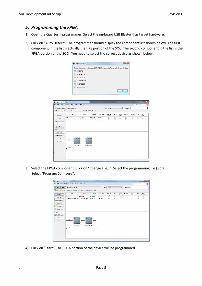
5. Programming the FPGA
1) Open the Quartus II programmer. Select the on-board USB Blaster II as target hardware.
2) Click on “Auto Detect”. The programmer should display the component list shown below. The first
component in the list is actually the HPS portion of the SOC. The second component in the list is the
FPGA portion of the SOC. You need to select the correct device as shown below:
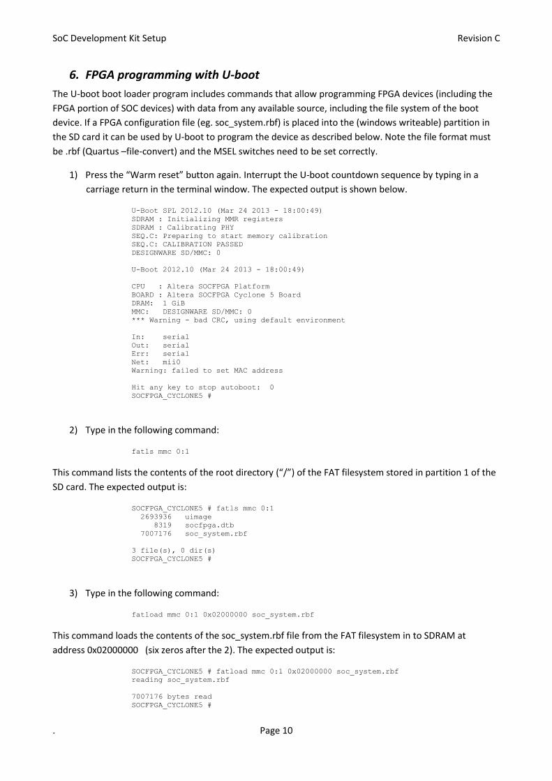
3) Select the FPGA component. Click on “Change File…”. Select the programming file (.sof).
Select “Program/Configure”.
4) Click on “Start”. The FPGA portion of the device will be programmed.
Page 10
SoC Development Kit Setup Revision C
. Page 10
6. FPGA programming with U-boot
The U-boot boot loader program includes commands that allow programming FPGA devices (including the
FPGA portion of SOC devices) with data from any available source, including the file system of the boot
device. If a FPGA configuration file (eg. soc_system.rbf) is placed into the (windows writeable) partition in
the SD card it can be used by U-boot to program the device as described below. Note the file format must
be .rbf (Quartus –file-convert) and the MSEL switches need to be set correctly.
1) Press the “Warm reset” button again. Interrupt the U-boot countdown sequence by typing in a
carriage return in the terminal window. The expected output is shown below.
U-Boot SPL 2012.10 (Mar 24 2013 - 18:00:49)
SDRAM : Initializing MMR registers
SDRAM : Calibrating PHY
SEQ.C: Preparing to start memory calibration
SEQ.C: CALIBRATION PASSED
DESIGNWARE SD/MMC: 0
U-Boot 2012.10 (Mar 24 2013 - 18:00:49)
CPU : Altera SOCFPGA Platform
BOARD : Altera SOCFPGA Cyclone 5 Board
DRAM: 1 GiB
MMC: DESIGNWARE SD/MMC: 0
*** Warning - bad CRC, using default environment
In: serial
Out: serial
Err: serial
Net: mii0
Warning: failed to set MAC address
Hit any key to stop autoboot: 0
SOCFPGA_CYCLONE5 #
2) Type in the following command:
fatls mmc 0:1
This command lists the contents of the root directory (“/”) of the FAT filesystem stored in partition 1 of the
SD card. The expected output is:
SOCFPGA_CYCLONE5 # fatls mmc 0:1
2693936 uimage
8319 socfpga.dtb
7007176 soc_system.rbf
3 file(s), 0 dir(s)
SOCFPGA_CYCLONE5 #
3) Type in the following command:
fatload mmc 0:1 0x02000000 soc_system.rbf
This command loads the contents of the soc_system.rbf file from the FAT filesystem in to SDRAM at
address 0x02000000 (six zeros after the 2). The expected output is:
SOCFPGA_CYCLONE5 # fatload mmc 0:1 0x02000000 soc_system.rbf
reading soc_system.rbf
7007176 bytes read
SOCFPGA_CYCLONE5 #
Page 11
SoC Development Kit Setup Revision C
. Page 11
4) Set the MSEL switches on the board (left to right) to up-up-down-up-up-up.
This sets MSEL to 110111 (FPP programming, uncompressed programming file).
5) Type in the following command:
fpga load 0 0x02000000 0x6af000
This command programs the FPGA portion of the SoC device using data from the SDRAM starting at address
0x02000000. The last parameter – 0x6af000 – is the programming file size in hexadecimal format. Note that
typing in the decimal number won’t work, since U-boot assumes all numbers to be hexadecimal.
If no error occurs, U-Boot silently displays the command prompt.
In case of errors, the message
“altera_load: Failed with error code <n>”
is displayed. (Code 4 – check MSEL switch settings up-up-down-up-up-up)
6) You can then start the Linux kernel boot typing in the command
run bootcmd
7. Run Linux
Log in as root using “root” as username at the Linux login prompt. The root account has no set password.
List the root filesystem directory tree typing in the command
ls /
List the /sys/class filesystem directory tree again typing in the command
ls /sys/class
Try:
echo “Hello World!” > /dev/ttyLCD0
Page 12
SoC Development Kit Setup Revision C
. Page 12
8. DS-5 License setup
After installing the EDS (and DS-5 Altera Edition), start Eclipse for DS-5.
This is located in the Windows 7 Start Menu under All Programs->ARM DS-5-> Eclipse for DS-5.
The Eclipse tool will start, first asking for the workspace folder to be used. Use the default folder and press
OK.
On the first tool launch the ARM DS-5 AE welcome screen will appear. Close it by clicking the Close button.
Page 13
SoC Development Kit Setup Revision C
. Page 13
If the License manager prompt does not pop up automatically then from the Help Menu, select the ARM
License Manager to set up your license.
Click Add License… if you get the error shown below you need to enable https services (usually by enabling
a proxy server) to be able to get evaluation license from ARM.
Page 14
SoC Development Kit Setup Revision C
. Page 14
Go here to look at licensing options http://ds.arm.com/altera/ (there are links and instructions here to the
other options)
Get an activation code for a 30 Day evaluation license from http://ds.arm.com/altera/altera-eval-edition/
(AC+70616421313531 – on 1 June 1013)
For Web edition go to http://ds.arm.com/altera/altera-community-edition/ and get the activation code
((AC+70616421313438 – on 1 June 2013)
OR (if you purchased the kit) enter your Serial number from your Kit customer letter.
Enter the code/number into the license manager and click next.
Select a NIC ID
Page 15
SoC Development Kit Setup Revision C
. Page 15
Select the correct kit (Evaluation for eval license, Altera Edition for kit serial number)
Your license should now be ready
9. Next Steps & More Information
Please refer to the EDS user guide (ug_soc_eds.pdf) for more information on how to start the example
applications included in the EDS.
For more information on the board setup please refer to the development kit user guide
(ug_cv_soc_dev_kit.pdf) or the development board reference manual (rm_cv_soc_dev_board.pdf).
For more information on the example FPGA design provided please consul the SoC Golden System Reference Design User Guide (ug_soc_gsrd.pdf). These files are all available for download from ww.altera.com. To test/exercise the board you may want to run the board test system or board update portal, these are included with the development kit installation and are documented in the Development kit quick start guide (qsg_cyclone5_soc_devkit.pdf). To get the installer pleas download it from the development kit page on www.altera.com For more information on SoC devices please refer to the Cyclone V documentation from Altera and the Cortex – A9 documentation from ARM (www.arm.com)
Page 16
SoC Development Kit Setup Revision C
. Page 16
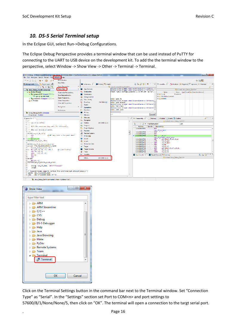
10. DS-5 Serial Terminal setup
In the Eclipse GUI, select Run->Debug Configurations.
The Eclipse Debug Perspective provides a terminal window that can be used instead of PuTTY for
connecting to the UART to USB device on the development kit. To add the the terminal window to the
perspective, select Window -> Show View -> Other -> Terminal -> Terminal.
Click on the Terminal Settings button in the command bar next to the Terminal window. Set “Connection
Type” as “Serial”. In the “Settings” section set Port to COM<n> and port settings to
57600/8/1/None/None/5, then click on “OK”. The terminal will open a connection to the targt serial port.
Page 17
SoC Development Kit Setup Revision C
. Page 17
This setup is persistent; to connect/disconnect the terminal to/from the target, you can now click on the
two green (connect) and red (disconnect) icons located at the left of the terminal settings icon. Only one of
these two icons is active at any time, depending on terminal status.