72
System-on-Chip Applications Instructor:
| Date post: | 28-Apr-2018 |
| Category: |
Documents |
| Upload: | truongcong |
| View: | 216 times |
| Download: | 0 times |

System-on-Chip Applications
Instructor:

Technology and System Outlook
2000

Outline
n More on Spread Spectrum Communication --CDMA
n Smart Antenna and Future Trend

CDMA & Spread Spectrum
n CDMA use Spread Spectrum technique n The unwanted signals with different codes get
spread even more, making them like noise to the receiver.

CDMA System Structure
DataSignal is Despread
Data Signal is Transmitted
Signal is Spread
Specified Range
Signal Received
Spread Spectrum Communication
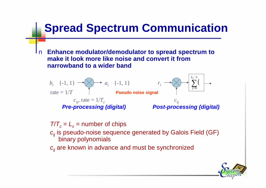
n Enhance modulator/demodulator to spread spectrum to make it look more like noise and convert it from narrowband to a wider band
T/Tc = Lc = number of chipscij is pseudo-noise sequence generated by Galois Field (GF)
binary polynomialscij are known in advance and must be synchronized
bi ∈{-1, 1} ai ∈{-1, 1}
cij, rate = 1/Tc
rate = 1/T
Pre-processing (digital) Post-processing (digital)
ri
cij
( )∑−
=
⋅1
0
cL
jPseudo noise signal

Spreading
A key

Example

Spread in Frequency Domain

Spreading & Despreading
With the same key

Despreading in Spectrum Domain
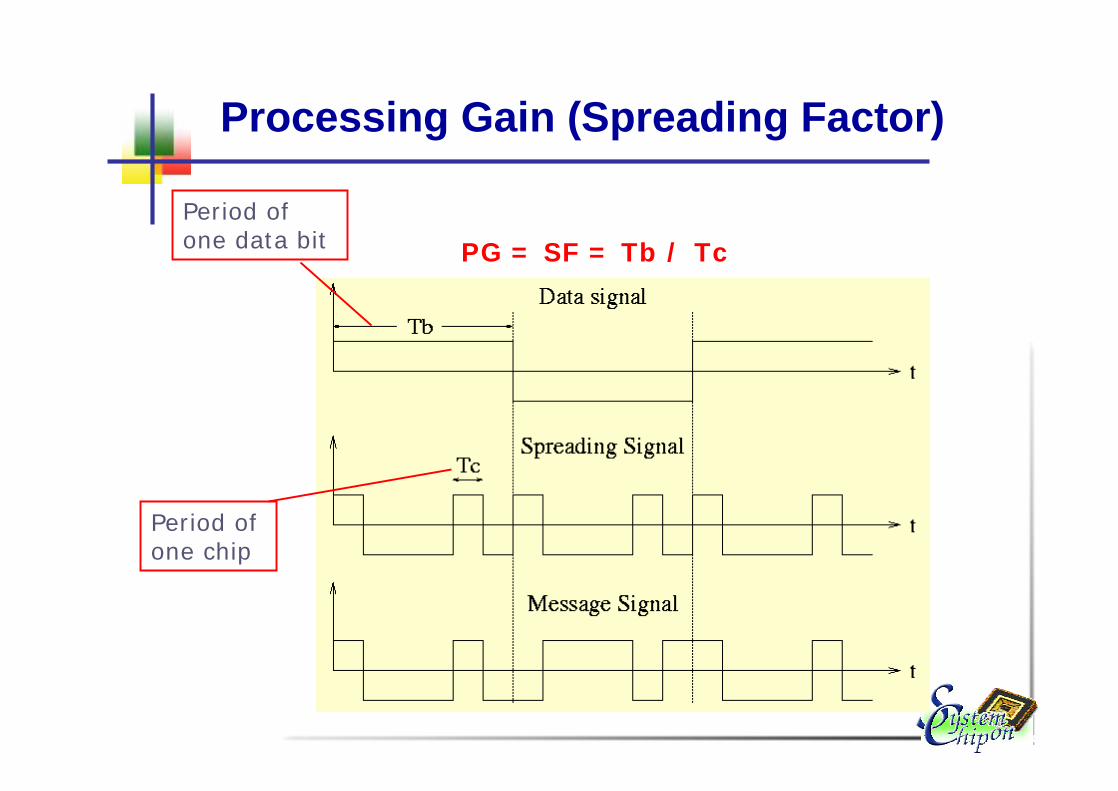
Processing Gain (Spreading Factor)
Period of one chip
Period of one data bit PG = SF = Tb / Tc
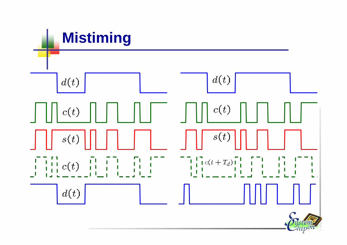
Mistiming

Pseudo Noise Signaln The pulse sent is a pseudo noise signaln Is sort of like a key
Receive
Trying to match the location of the signal
Success!
Transmit
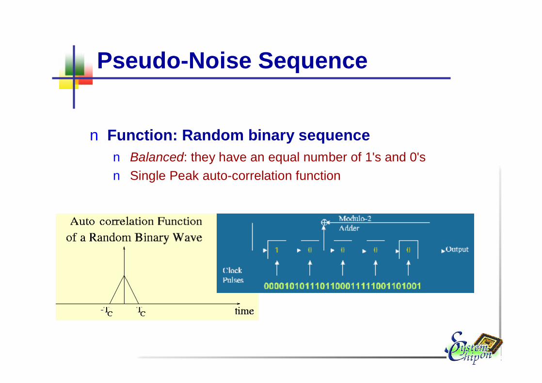
Pseudo-Noise Sequence
n Function: Random binary sequencen Balanced: they have an equal number of 1's and 0's n Single Peak auto-correlation function

Hadamard-Walsh Codes
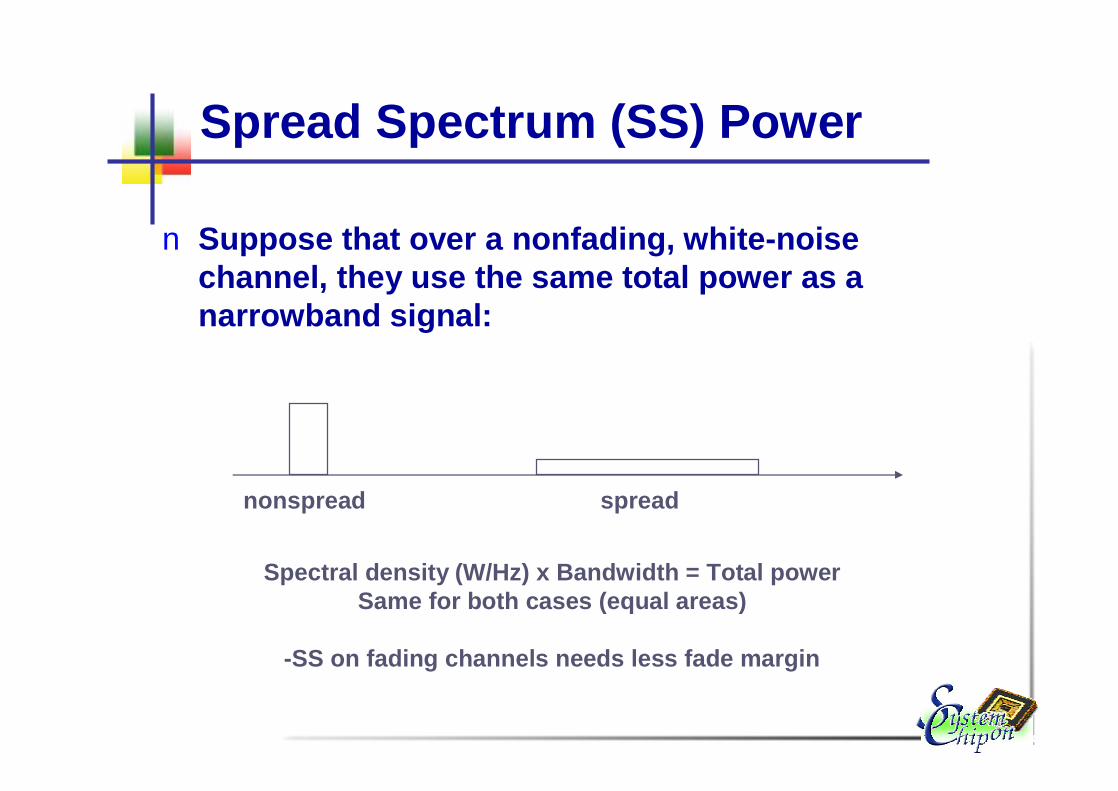
Spread Spectrum (SS) Power
n Suppose that over a nonfading, white-noise channel, they use the same total power as a narrowband signal:
nonspread spread
Spectral density (W/Hz) x Bandwidth = Total powerSame for both cases (equal areas)
-SS on fading channels needs less fade margin
Spread Spectrum History
n First patent proposal in 1941n 1949 Shannon and Pierce developed basic ideas of CDMAn Rake receiver patent in 1956n Cellular applications proposed late 70sn Investigations for cellular use 80sn IS-95 standard 1993n Commercial introduction in 1995
n 1997/1998 3G technology choice CDMAn …
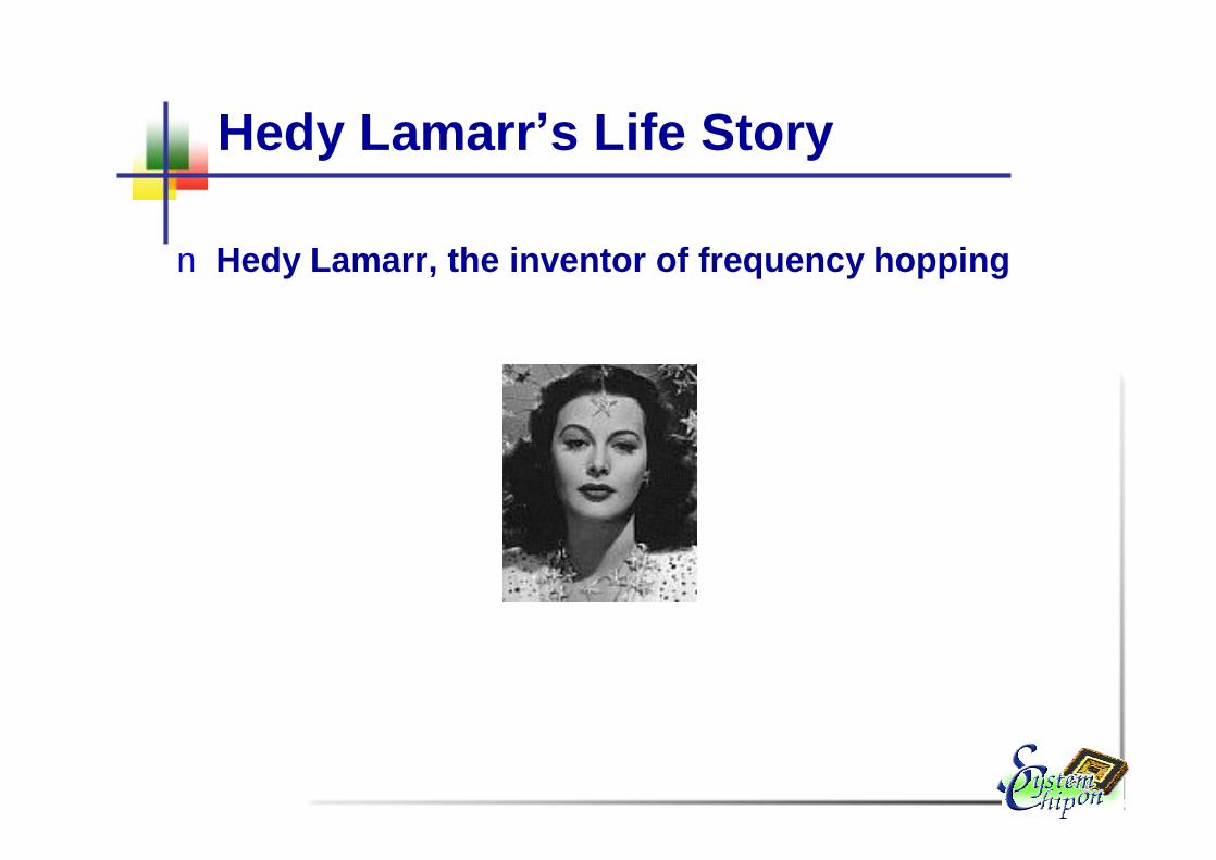
Hedy Lamarr’s Life Story
n Hedy Lamarr, the inventor of frequency hopping

Frequency Hopping

The UMTS Propositionn UMTS: Designed as a complete, end-to-end mobile systemn UMTS offers cost efficient, wide area network coveragen UMTS is universally standard, using licensed radio
spectrum, globally harmonized in common bandsn UMTS offers user bit rate up to 384kbps in high mobility
situations/ 2Mbps stationary, with a roadmap to >10Mbps for low mobility/indoor use
n UMTS supports a rich choice of services and applications optimized for fully mobile environments
n UMTS supports international roaming, with a wide range of handheld terminals
n UMTS offers integrated charging and billing functionsn UMTS offers integral security

The WLAN Proposition
n WLAN: low mobility, high speed wireless access to public and private networks
n WLAN serves as a wire-free access to existing data networks with limited mobility around hot spots.
n WLAN offers theoretical access speeds of 11Mbps ~ 54Mbps shared between users (actual data rate reduces with increasing distance from access point)
n Currently uses license exempt radio spectrum shared with other applications and users
n WLAN currently optimized for IT industry modelsn Choice of affordable WLAN hardware – including PC cards,
routers, and so on

WLAN v.s. UMTS
n WLAN gives hot spot coverage; UMTS gives full mobility
n Can WLAN be integrated easily with operators’? n Can voice be integrated into a WLAN offering?

Mobile Phone Today = Multipurpose Terminal for ...
Information Client
Internet Browser
E-mail Client
Authentication Device
E-purse
Share dealing, etc.
mobile computing
Mobile Multimedia System
Mobile Computing
n Information processing in generaln not just communication or just computing, but both
n Any medium or combination of mediumn process not just telephone voice or just data, but multimedia
n Mobilityn components of the systems may ben moving, tether-less (wireless), portable
n uses of the system may be moving
Mobile Multimedia Systems
n Ubiquitous information access (everybody else)n e.g. wireless computing, mobile computing, nomadic
computingn information distributed everywhere by “the net”n users carry (wireless) terminals to access the
information servicesn terminal is the universal service access devicen terminals adapt to location and services
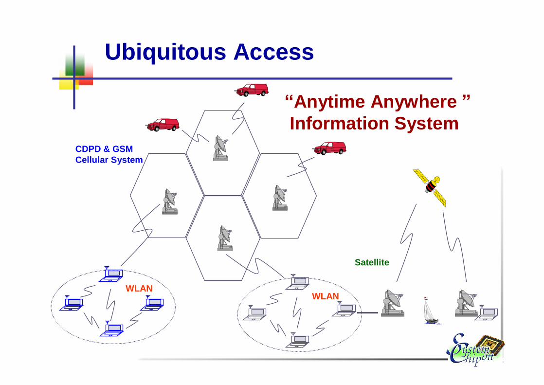
WLAN
CDPD & GSMCellular System
WLAN
Satellite
Ubiquitous Access
“Anytime Anywhere ”Information System

Base-station vs Peer-to-Peer Models
WLAN
Base-station(infrastructure-centralized)
Peer-to-Peer(ad hoc network- vs multihop)

Cellular based
E.g.: GSM Network Infrastructure
MSC
G-MSCPSTN / ISDN
BTSBTS
BTSBSC
BTSBTS
BTSBSC
HLRAUC
EIR
VLR
E1 Trunks
BSS
r

r
r
Ad-hoc network
n No centralized controller ( base stations )n No wired inter-connection backbonen Forwarding function should be provided by
mobile nodes

System Configurations
n Ad hoc ~ Multi-hopn Wireless LANn Blue-toothn Packet Radion WAMIS
nCellular ~ GSM, WAP, GPRS, 3G
n Satellite ~ LEO, GEO More Detailed..

Cellular Revolution and Evolution
n 1st generation: analog technology (for voice)n Analog signal, AMPS system
n 2nd generation: digital architecture (voice & data)n Spread spectrum signaln Frequency hopping GSM architecturen In Europe
n Spread-spectrum CDMA technologyn In US, parts of Asia
n 3nd generation: digital architecture (Multimedia)n WCDMA

Cellular Generation

2G v.s. 3G

Cellular Radio Communication Principles
n Public radio communications should offer duplex communication
n The signal strength deteriorates together with distance
n Every transmitter can offer only limited amount of simultaneously radio links to the end-users
n Cellular conceptn Large area is divided into a number of sub-areas
(or cells)n Each cell has its base-station (BS) which is able
to provide a radio link for number of simultaneously users
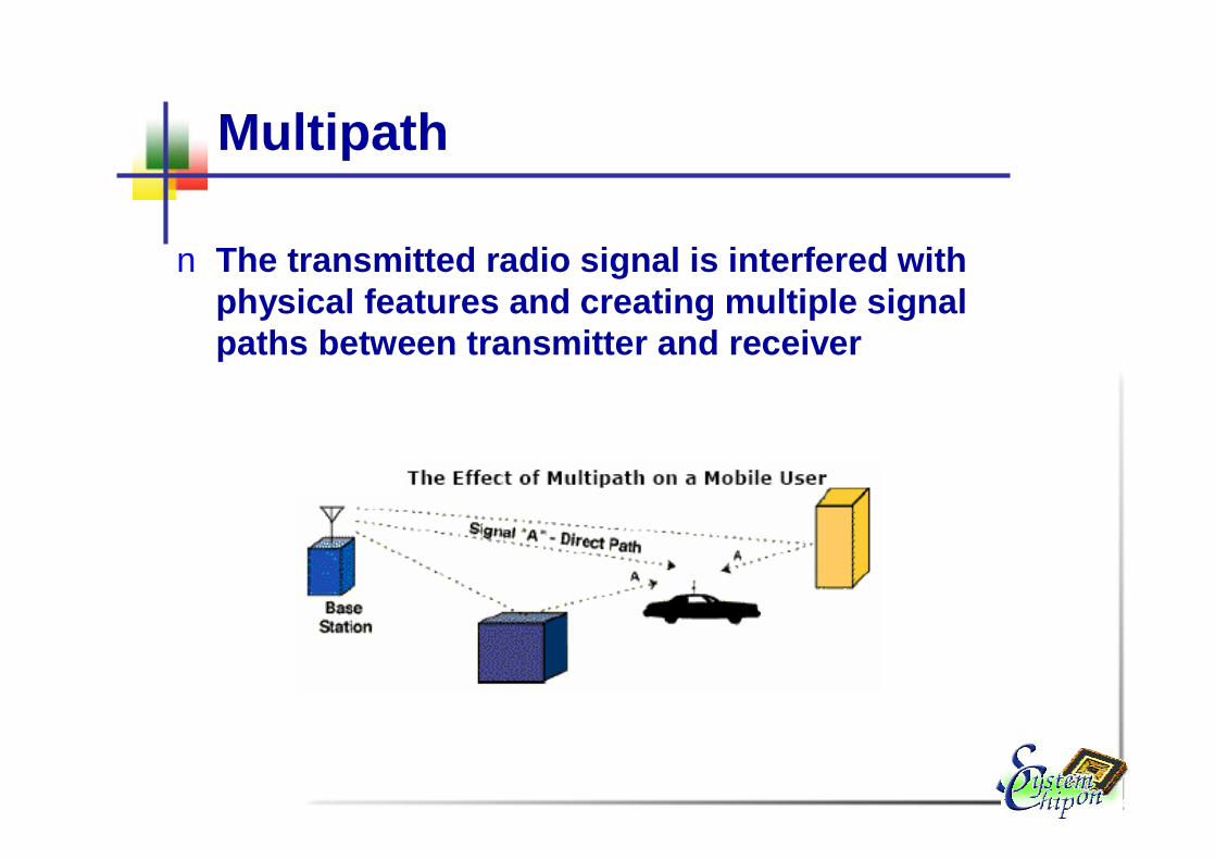
Multipath
n The transmitted radio signal is interfered with physical features and creating multiple signal paths between transmitter and receiver

Signal Propagation
n Path Lossn Shadowingn Multipath
d
Pr/Pt
d=vt

Fading
n When the waves of multipath signals are out of phase, reduction in signal strength occurs.
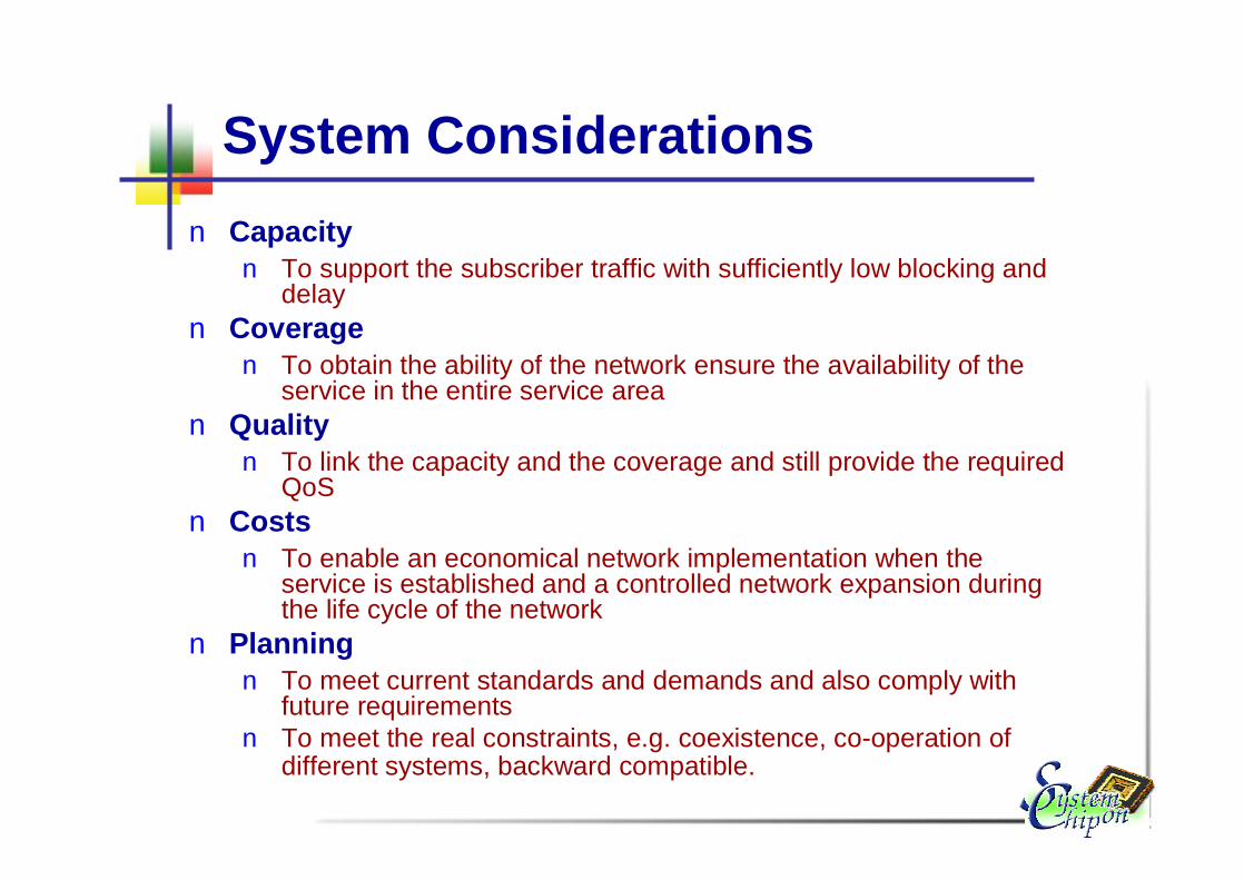
System Considerationsn Capacityn To support the subscriber traffic with sufficiently low blocking and
delayn Coverage
n To obtain the ability of the network ensure the availability of the service in the entire service area
n Qualityn To link the capacity and the coverage and still provide the required
QoSn Costs
n To enable an economical network implementation when the service is established and a controlled network expansion duringthe life cycle of the network
n Planningn To meet current standards and demands and also comply with
future requirementsn To meet the real constraints, e.g. coexistence, co-operation of
different systems, backward compatible.

Architecture of Mobile Systems
n Design Problemsn Interference due to the cellular structure, inter-/intra-cell
interferencen Mobility handlingn Cell based radio resource scarcity
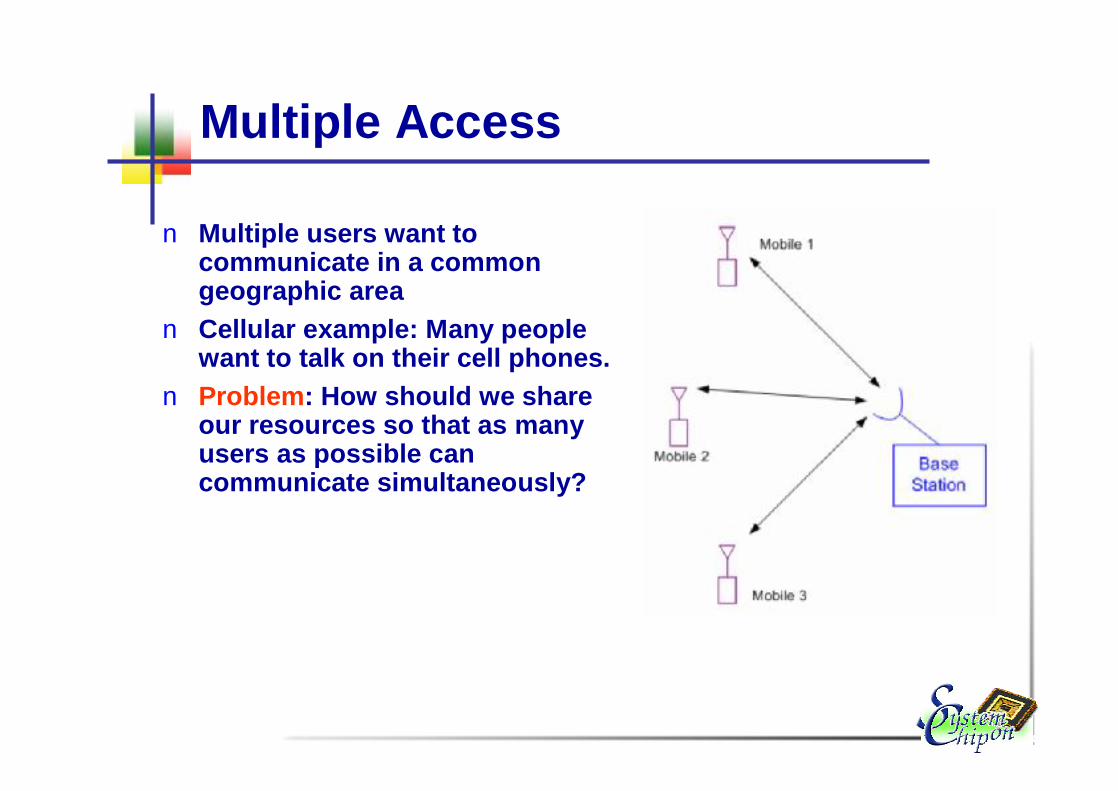
Multiple Access
n Multiple users want to communicate in a common geographic area
n Cellular example: Many people want to talk on their cell phones.
n Problem: How should we share our resources so that as many users as possible can communicate simultaneously?
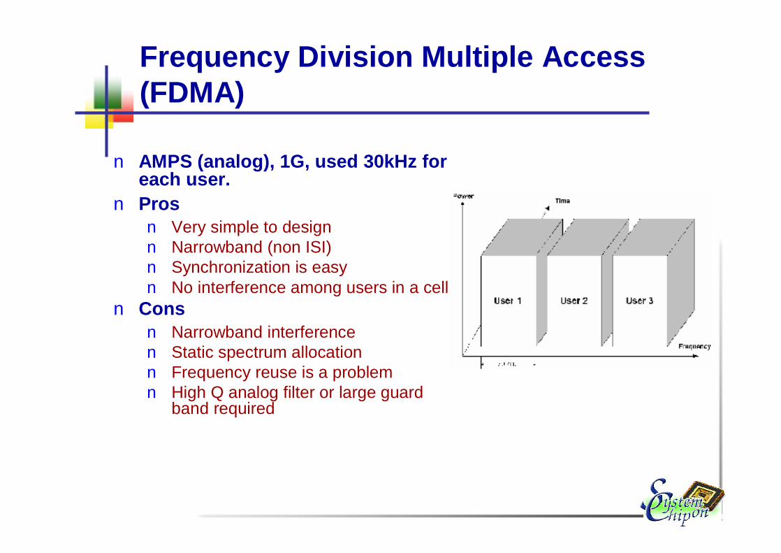
Frequency Division Multiple Access (FDMA)
n AMPS (analog), 1G, used 30kHz for each user.
n Prosn Very simple to designn Narrowband (non ISI)n Synchronization is easyn No interference among users in a cell
n Consn Narrowband interferencen Static spectrum allocationn Frequency reuse is a problemn High Q analog filter or large guard
band required

Time Division Multiple Access (TDMA)
n Users take turns using the channel
n IS-54, 2G, used 30kHz channel, but with three users sharing them
n GSM, 2G, has 8 slots/270kHzn Pros
n Better suited for digitaln Often gets higher capacity (3 times
higher in IS-54)n Cons
n Strict synchronization and guard time needed
n Still susceptible to jamming, other-cell interference
n Often requires equalizer

FDMA v.s. TDMA
FDMA TDMA
Disadvantages
n In TDMAn High unused physical resources due to short transmission
time and relatively long set up and release timen High variation in the interference levels due to high bit rate
and burst trafficn Limited uplink range of high bit rate due to mobile’s limited
transmission power
n In FDMAn Similar to TDMA

Spread Spectrum
n Transmission bandwidth is much larger than information bandwidth
n Bandwidth does not depend on the informational signaln Processing gain = transmitted bandwidth / information
bandwidthn Classification
n Direct sequence: data is scrambled by user specific pseudo noisecode at the transmitter side
n Frequency hopping: signal is spread by changing the frequency over the transmitted time of the signal

Code-Division Multiple Access (CDMA)
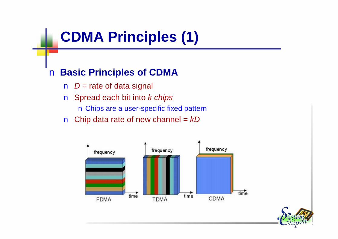
CDMA Principles (1)
n Basic Principles of CDMAn D = rate of data signaln Spread each bit into k chipsn Chips are a user-specific fixed pattern
n Chip data rate of new channel = kD

CDMA Principles (2)
n Example
CDMA Principles (3)
n An alternative to the GSM cellular architecturen All users transmit in the same bandwidth
simultaneously. n The system bandwidth occupancy is much higher
than users required.
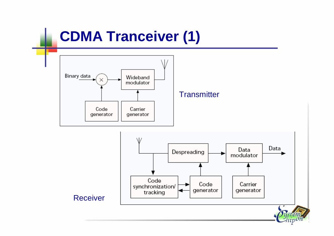
CDMA Tranceiver (1)
Transmitter
Receiver

CDMA Tranceiver (2)

CDMA Example (1)
n If k=6 and code is a sequence of 1s and -1sn For a ‘1’ bit, A sends code as chip pattern
n <c1, c2, c3, c4, c5, c6>n For a ‘0’ bit, A sends complement of code
n <-c1, -c2, -c3, -c4, -c5, -c6>n Receiver knows sender’s code and performs electronic
decode function
n <d1, d2, d3, d4, d5, d6> = received chip patternn <c1, c2, c3, c4, c5, c6> = sender’s code
( ) 665544332211 cdcdcdcdcdcddSu ×+×+×+×+×+×=

CDMA Example (2)n User A code = <1, –1, –1, 1, –1, 1>n To send a 1 bit = <1, –1, –1, 1, –1, 1>n To send a 0 bit = <–1, 1, 1, –1, 1, –1>
n User B code = <1, 1, –1, – 1, 1, 1>n To send a 1 bit = <1, 1, –1, –1, 1, 1>
n Receiver receiving with A’s coden (A’s code) x (received chip pattern)n User A ‘1’ bit: 6 -> 1n User A ‘0’ bit: -6 -> 0n User B ‘1’ bit: 0 -> unwanted signal ignored

Advantages of CDMA
n Low power spectral densityn But Gaussian Noise level is increasing
n Interference limited operationn Privacy due to unknown random codesn Reduction of multi-path effectsn Random access possibilities


CDMA Design Issues
n Tight synchronization is requiredn Spreading codes cause self-interferencen Fast power control is necessary to overcome the
near-far problemn Rake receiver design

Power Control in CDMA Systems
n All users transmit on the same frequency in CDMA systemn Internal interference is the most significant factor in
determining system capacity and call qualityn Reduce internal interference è to limit the transmit power
for each usern The power, however, should be enough to maintain the
required SNR for a satisfactory call quality.n Maximum capacity is achieved when SNR of every user is
at the minimum level needed for the acceptable channel performance.

Backbone Network
User Moves
Handover
Handover (1)

Handover (2)
n When a call has to be passed form one cell to another, handover occurs.
n Scheme n Break-before-make handover (hard)n Make-before-break handover (soft)
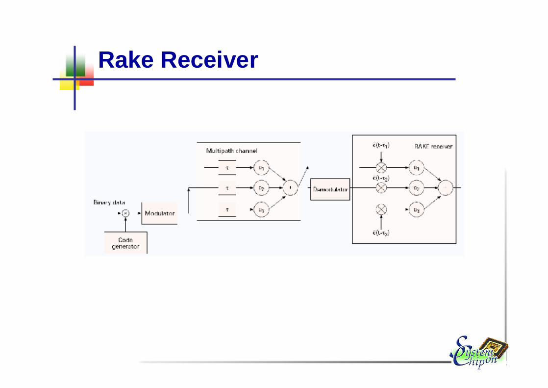
Rake Receiver
Future Trends and Technologies
n Multi-antenna systems (MIMO)n Ultra wide band (UWB, 802.15)n Software-defined radio (SDR)n Ad hoc and sensor networkn Fixed (or semi-fixed) Broadband (802.16)
n èTrend towards ever higher integration of systems (4G? Or beyond…)
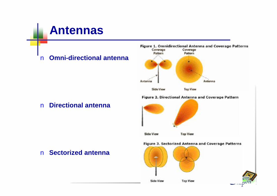
Antennas
n Omni-directional antenna
n Directional antenna
n Sectorized antenna

Diversity
n More than two antennas systems, diversity offers an improvement in the effective strength of the received signal by n Switched diversity: to connect each of the receiving
channels to the best serving antennan Diversity combining: to correct the phase error in multipath
signals and effectively combine the power of multipathsignals to produce gain

Diversity Gain
Switched Diversity
Combined Diversity

Smart Antenna System
n Effectively take the advantage of diversity gainn Using advanced digital signal processing
algorithm
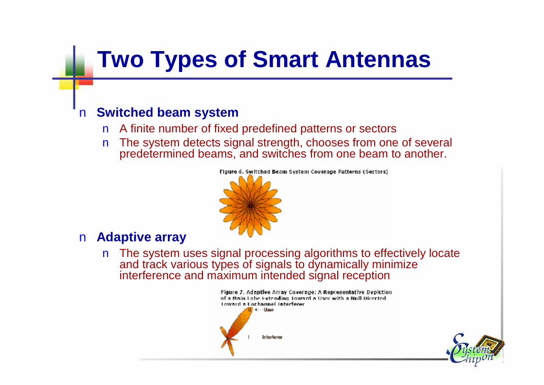
Two Types of Smart Antennas
n Switched beam systemn A finite number of fixed predefined patterns or sectorsn The system detects signal strength, chooses from one of several
predetermined beams, and switches from one beam to another.
n Adaptive arrayn The system uses signal processing algorithms to effectively locate
and track various types of signals to dynamically minimize interference and maximum intended signal reception

MIMO
n Multiple antennas at both transmitter and receiver sides to increase channel capacity, and hence data rate

Ultra Wide Band
n Very short or quick pulsesn Very wide low-power spectrum (several GHz)n Two possible proposalsn Spread spectrum (Motorola)n OFDM (Intel/TI)

Software Defined Radio
n To allow a single device to implement many different standards by simply loading different software
n Adv.: Flexible and adaptiven Disadv.: High power consumptionn ASIC 10x more efficient than DSPn DSP 10x more efficient than generous-purpose micro-
processorn Wideband analog front end: difficult to implement

Ad Hoc and Sensor Networks
n Military communication, search and rescuen Range extension of WLAN/Cellularn Ultra-low power sensor network

Parameters of Ad Hoc networks
n Challengen Mobilityn Scalability n Power
n Minimizing power consumption during the idle time n Minimizing power consumption during communication
n QoSn End to End delayn Bandwidth management n Probability of packet loss


