27
LEGAL NOTICES AND CONTACT INFORMATION 1 SocketModem Cell HSPA and SocketModem iCell HSPA MTSMC-H5 Device Guide SocketModem® Cell HSPA+ SocketModem® iCell HSPA+ MTSMC-H5 Device Guide
LEGAL NOTICES AND CONTACT INFORMATION
1 SocketModem Cell HSPA and SocketModem iCell HSPA MTSMC-H5 Device Guide
SocketModem® Cell HSPA+ SocketModem® iCell HSPA+ MTSMC-H5 Device Guide
LEGAL NOTICES AND CONTACT INFORMATION
SocketModem Cell HSPA and SocketModem iCell HSPA MTSMC-H5 Device Guide 2
SocketModem Cell HSPA+ and SocketModem iCell HSPA+ MTSMC-H5 Device Guide S000540, Version C MTSMC-H5, MTSMC-H5-U, MTSMC-H5-IP, MTSMC-H5-GP
Copyright This publication may not be reproduced, in whole or in part, without the specific and express prior written permission signed by an executive officer of Multi-Tech Systems, Inc. All rights reserved. Copyright © 2013 by Multi-Tech Systems, Inc.
Multi-Tech Systems, Inc. makes no representations or warranties, whether express, implied or by estoppels, with respect to the content, information, material and recommendations herein and specifically disclaims any implied warranties of merchantability, fitness for any particular purpose and non-infringement.
Multi-Tech Systems, Inc. reserves the right to revise this publication and to make changes from time to time in the content hereof without obligation of Multi-Tech Systems, Inc. to notify any person or organization of such revisions or changes.
Trademarks Multi Tech, SocketModem, SocketWireless, Universal IP, SocketEthernet IP and the Multi-Tech logo are registered trademarks of Multi-Tech Systems, Inc. All other brand and product names are trademarks or registered trademarks of their respective companies.
Legal Notices The Multi-Tech products are not designed, manufactured or intended for use, and should not be used, or sold or re-sold for use, in connection with applications requiring fail-safe performance or in applications where the failure of the products would reasonably be expected to result in personal injury or death, significant property damage, or serious physical or environmental damage. Examples of such use include life support machines or other life preserving medical devices or systems, air traffic control or aircraft navigation or communications systems, control equipment for nuclear facilities, or missile, nuclear, biological or chemical weapons or other military applications (“Restricted Applications”). Use of the products in such Restricted Applications is at the user’s sole risk and liability.
MULTI-TECH DOES NOT WARRANT THAT THE TRANSMISSION OF DATA BY A PRODUCT OVER A CELLULAR COMMUNICATIONS NETWORK WILL BE UNINTERRUPTED, TIMELY, SECURE OR ERROR FREE, NOR DOES MULTI-TECH WARRANT ANY CONNECTION OR ACCESSIBILITY TO ANY CELLULAR COMMUNICATIONS NETWORK. MULTI-TECH WILL HAVE NO LIABILITY FOR ANY LOSSES, DAMAGES, OBLIGATIONS, PENALTIES, DEFICIENCIES, LIABILITIES, COSTS OR EXPENSES (INCLUDING WITHOUT LIMITATION REASONABLE ATTORNEYS FEES) RELATED TO TEMPORARY INABILITY TO ACCESS A CELLULAR COMMUNICATIONS NETWORK USING THE PRODUCTS.
The Multi-Tech products and the final application of the Multi-Tech products should be thoroughly tested to ensure the functionality of the Multi-Tech products as used in the final application. The designer, manufacturer and reseller has the sole responsibility of ensuring that any end user product into which the Multi-Tech product is integrated operates as intended and meets its requirements or the requirements of its direct or indirect customers. Multi-Tech has no responsibility whatsoever for the integration, configuration, testing, validation, verification, installation, upgrade, support or maintenance of such end user product, or for any liabilities, damages, costs or expenses associated therewith, except to the extent agreed upon in a signed written document. To the extent Multi-Tech provides any comments or suggested changes related to the application of its products, such comments or suggested changes is performed only as a courtesy and without any representation or warranty whatsoever.
Contacting Multi-Tech Knowledge Base The Knowledge Base provides immediate access to support information and resolutions for all Multi-Tech products. Visit http://www.multitech.com/kb.go.
Support Portal
To create an account and submit a support case directly to our technical support team, visit: https://support.multitech.com.
Support Business Hours: M-F, 9am to 5pm CT
Country By Email By Phone
Europe, Middle East, Africa: [email protected] +(44) 118 959 7774
U.S., Canada, all others: [email protected] (800) 972-2439 or (763) 717-5863
World Headquarters Multi-Tech Systems, Inc. 2205 Woodale Drive Mounds View, Minnesota 55112 Phone: 763-785-3500 or 800-328-9717 Fax: 763-785-9874
Warranty To read the warranty statement for your product, please visit: http://www.multitech.com/warranty.go.
CONTENTS
3 SocketModem Cell HSPA and SocketModem iCell HSPA MTSMC-H5 Device Guide
Contents Chapter 1 – Device Overview ......................................................................................................................................5
Description .......................................................................................................................................................................... 5
Product Build Options ......................................................................................................................................................... 5
Documentation ................................................................................................................................................................... 6
Chapter 2 – Mechanical Drawing ................................................................................................................................7
MTSMC-H5 All Builds .......................................................................................................................................................... 7
Chapter 3 – Specifications ..........................................................................................................................................8
Technical Specifications ...................................................................................................................................................... 8
Mounting Hardware ............................................................................................................................................................ 9
Recommended Parts ......................................................................................................................................................................... 9
Device Reset ...................................................................................................................................................................... 10
DC Electrical Characteristics .............................................................................................................................................. 10
Absolute Maximum Rating .............................................................................................................................................................. 10
Electrical Specifications ..................................................................................................................................................... 10
Pinout Specifications ......................................................................................................................................................... 11
Pin 58 .............................................................................................................................................................................................. 12
Pin Availability by Build ..................................................................................................................................................... 12
Power Measurements ....................................................................................................................................................... 13
MTSMC-H5 ...................................................................................................................................................................................... 13 MTSMC-H5-U .................................................................................................................................................................................. 14 MTSMC-H5-IP .................................................................................................................................................................................. 15 MTSMC-H5-GP ................................................................................................................................................................................ 17 Additional Information for the MTSMC-H5 Serial Device ............................................................................................................... 18 Set Phone and Registration Functionality +CFUN ........................................................................................................................... 19 GSM Power Saving Modes for Serial Devices.................................................................................................................................. 20 RTS Control of Power Mode AT+CFUN=9........................................................................................................................................ 20 DTR Control of Power Mode AT+CFUN=5 ....................................................................................................................................... 20
Chapter 4 – Device Specific Regulatory Information .................................................................................................. 22
FCC Part 15 ........................................................................................................................................................................ 22
FCC Grant Parts 22, 24, and 27 ......................................................................................................................................... 22
Industry Canada ................................................................................................................................................................ 23
EMC, Safety, and R&TTE Directive Compliance ................................................................................................................ 23
Chapter 5 – Application Notes .................................................................................................................................. 25
LED Interface ..................................................................................................................................................................... 25
LED 1 – Heartbeat – IP and –GP Builds Only ................................................................................................................................... 25
CONTENTS
SocketModem Cell HSPA and SocketModem iCell HSPA MTSMC-H5 Device Guide 4
LED 2 – Link Status – All Builds ........................................................................................................................................................ 25 LED 3 – Signal Strength –IP and –GP Builds Only ............................................................................................................................ 25 LED 4 – GPS Status – GP Builds ....................................................................................................................................................... 26
RF Performances ............................................................................................................................................................... 26
Receiver Features ............................................................................................................................................................................ 26 Transmitter Features....................................................................................................................................................................... 26 RF Connection and Antenna ........................................................................................................................................................... 26
Frequency Bands ............................................................................................................................................................... 27
CHAPTER 1 – DEVICE OVERVIEW
5 SocketModem Cell HSPA and SocketModem iCell HSPA MTSMC-H5 Device Guide
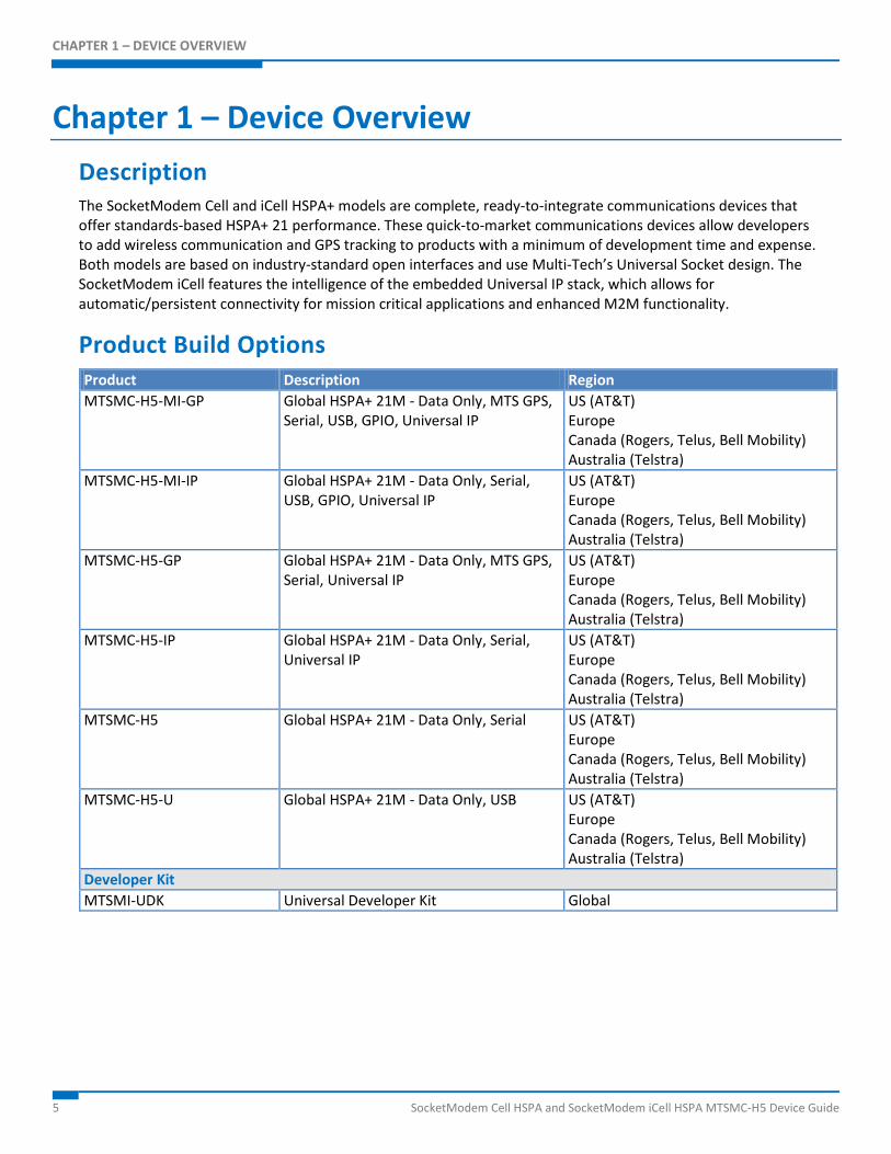
Chapter 1 – Device Overview Description The SocketModem Cell and iCell HSPA+ models are complete, ready-to-integrate communications devices that offer standards-based HSPA+ 21 performance. These quick-to-market communications devices allow developers to add wireless communication and GPS tracking to products with a minimum of development time and expense. Both models are based on industry-standard open interfaces and use Multi-Tech’s Universal Socket design. The SocketModem iCell features the intelligence of the embedded Universal IP stack, which allows for automatic/persistent connectivity for mission critical applications and enhanced M2M functionality.
Product Build Options Product Description Region MTSMC-H5-MI-GP Global HSPA+ 21M - Data Only, MTS GPS,
Serial, USB, GPIO, Universal IP US (AT&T) Europe Canada (Rogers, Telus, Bell Mobility) Australia (Telstra)
MTSMC-H5-MI-IP Global HSPA+ 21M - Data Only, Serial, USB, GPIO, Universal IP
US (AT&T) Europe Canada (Rogers, Telus, Bell Mobility) Australia (Telstra)
MTSMC-H5-GP Global HSPA+ 21M - Data Only, MTS GPS, Serial, Universal IP
US (AT&T) Europe Canada (Rogers, Telus, Bell Mobility) Australia (Telstra)
MTSMC-H5-IP Global HSPA+ 21M - Data Only, Serial, Universal IP
US (AT&T) Europe Canada (Rogers, Telus, Bell Mobility) Australia (Telstra)
MTSMC-H5 Global HSPA+ 21M - Data Only, Serial US (AT&T) Europe Canada (Rogers, Telus, Bell Mobility) Australia (Telstra)
MTSMC-H5-U Global HSPA+ 21M - Data Only, USB US (AT&T) Europe Canada (Rogers, Telus, Bell Mobility) Australia (Telstra)
Developer Kit MTSMI-UDK Universal Developer Kit Global
CHAPTER 1 – DEVICE OVERVIEW
SocketModem Cell HSPA and SocketModem iCell HSPA MTSMC-H5 Device Guide 6
Notes: These units ship without network activation. To connect them to the cellular network, you need a cellular
account. For more information, refer to Account Activation for Cellular Devices in the Universal Socket Developer’s Guide.
GP devices have a dedicated GPS receiver. MI devices have multiple interfaces. The complete product code may end in .Rx. For example, MTSMC-H5.Rx, where R is revision and x is the revision
number. All builds can be ordered individually or in 50-packs.
Documentation The following documentation is available by email to [email protected] or by using the Developer Guide Request Form on the multitech.com
Device Guide – This document. Provides model-specific specifications and developer information. Universal Socket Developer Guide – Provides an overview, safety and regulatory information, design
considerations, schematics, and general device information. (S000342) USB Driver Installation Guide – Provides steps for installing USB drivers. (S000533) AT Command Guide – Use the following AT Command Guides with HSPA devices:
S000528 for H5 Modems S000457 Universal IP Commands
CHAPTER 3 – SPECIFICATIONS
7 SocketModem Cell HSPA and SocketModem iCell HSPA MTSMC-H5 Device Guide
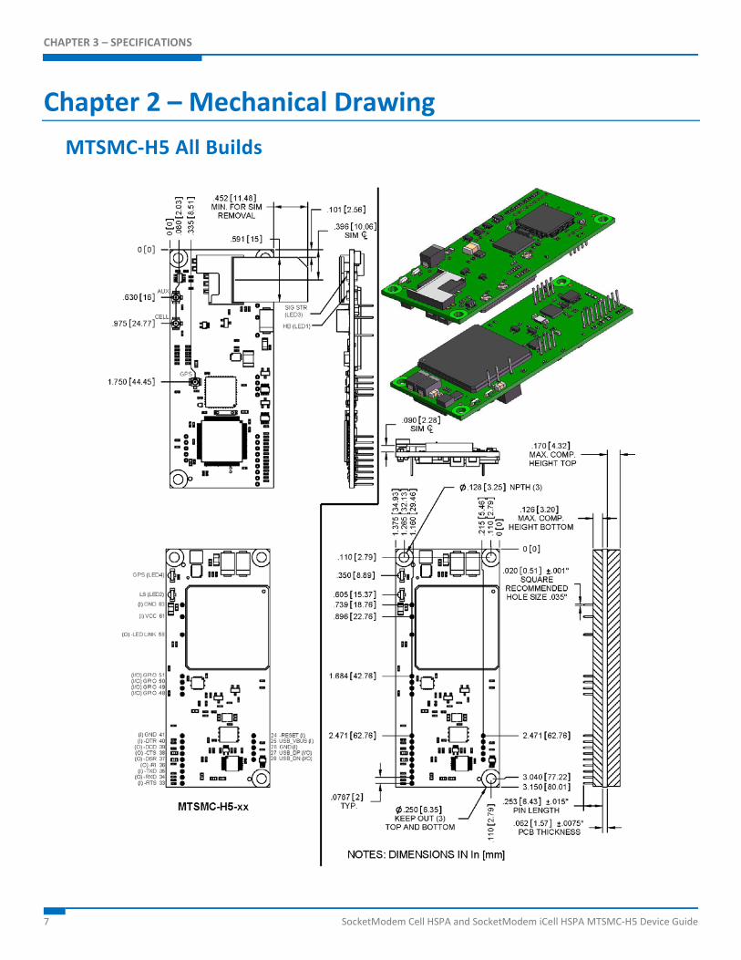
Chapter 2 – Mechanical Drawing MTSMC-H5 All Builds
CHAPTER 3 – SPECIFICATIONS
SocketModem Cell HSPA and SocketModem iCell HSPA MTSMC-H5 Device Guide 8
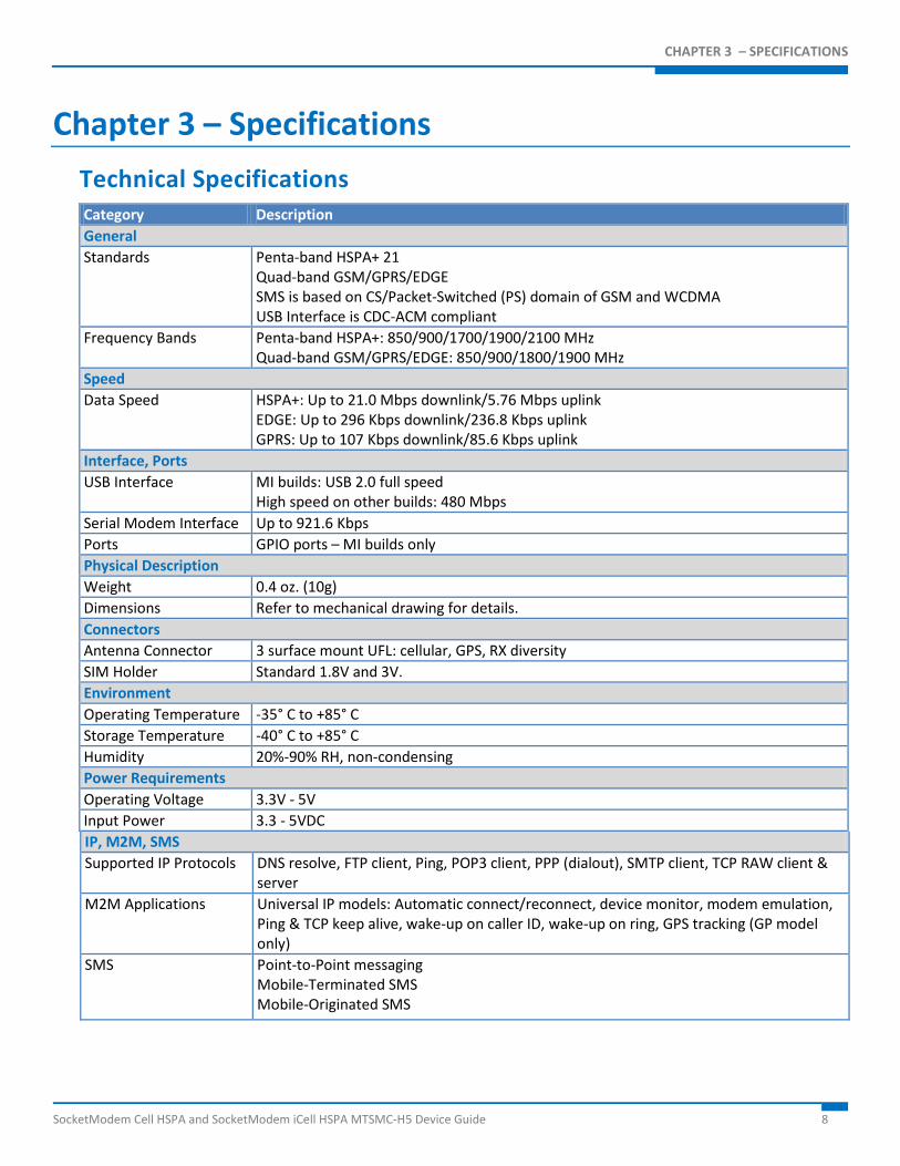
Chapter 3 – Specifications Technical Specifications Category Description General Standards Penta-band HSPA+ 21
Quad-band GSM/GPRS/EDGE SMS is based on CS/Packet-Switched (PS) domain of GSM and WCDMA USB Interface is CDC-ACM compliant
Frequency Bands Penta-band HSPA+: 850/900/1700/1900/2100 MHz Quad-band GSM/GPRS/EDGE: 850/900/1800/1900 MHz
Speed Data Speed HSPA+: Up to 21.0 Mbps downlink/5.76 Mbps uplink
EDGE: Up to 296 Kbps downlink/236.8 Kbps uplink GPRS: Up to 107 Kbps downlink/85.6 Kbps uplink
Interface, Ports USB Interface MI builds: USB 2.0 full speed
High speed on other builds: 480 Mbps Serial Modem Interface Up to 921.6 Kbps Ports GPIO ports – MI builds only Physical Description Weight 0.4 oz. (10g) Dimensions Refer to mechanical drawing for details. Connectors Antenna Connector 3 surface mount UFL: cellular, GPS, RX diversity SIM Holder Standard 1.8V and 3V. Environment Operating Temperature -35° C to +85° C Storage Temperature -40° C to +85° C Humidity 20%-90% RH, non-condensing Power Requirements Operating Voltage 3.3V - 5V Input Power 3.3 - 5VDC IP, M2M, SMS Supported IP Protocols DNS resolve, FTP client, Ping, POP3 client, PPP (dialout), SMTP client, TCP RAW client &
server M2M Applications Universal IP models: Automatic connect/reconnect, device monitor, modem emulation,
Ping & TCP keep alive, wake-up on caller ID, wake-up on ring, GPS tracking (GP model only)
SMS Point-to-Point messaging Mobile-Terminated SMS Mobile-Originated SMS
CHAPTER 3 – SPECIFICATIONS
9 SocketModem Cell HSPA and SocketModem iCell HSPA MTSMC-H5 Device Guide
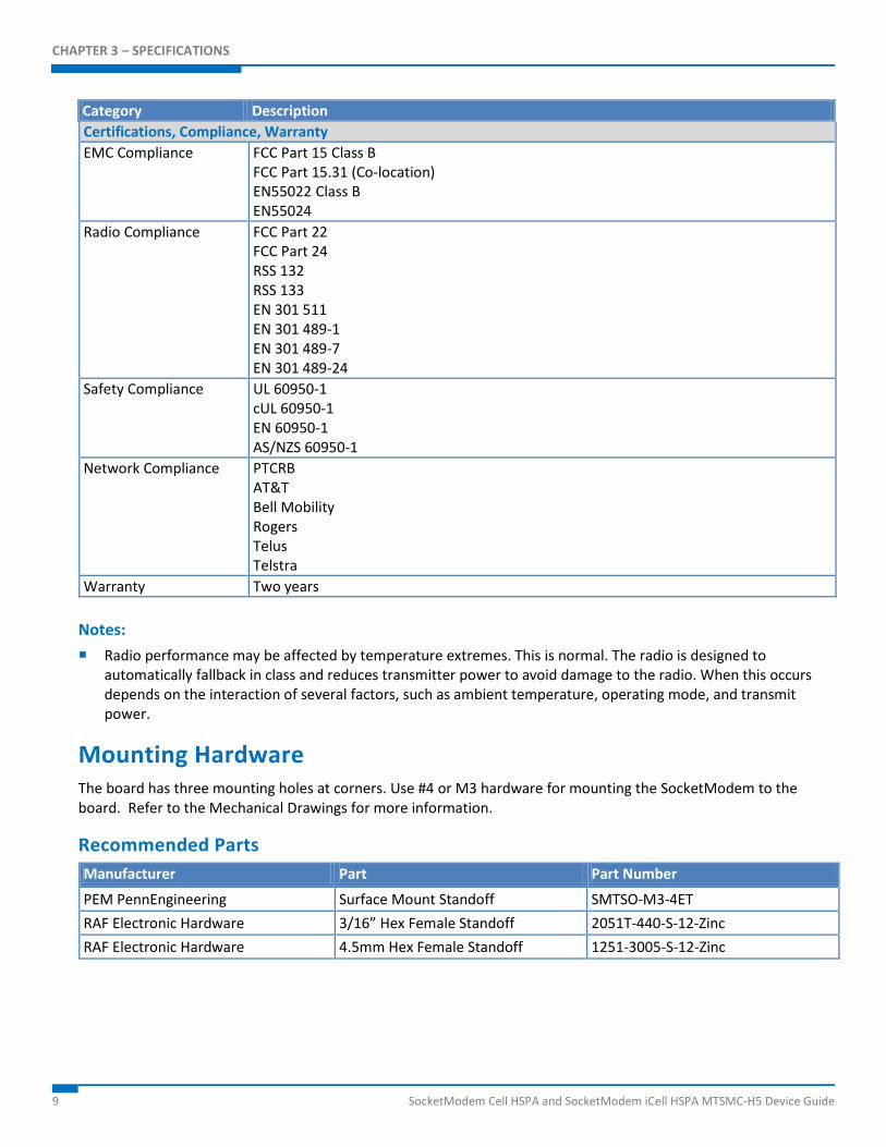
Category Description Certifications, Compliance, Warranty EMC Compliance FCC Part 15 Class B
FCC Part 15.31 (Co-location) EN55022 Class B EN55024
Radio Compliance FCC Part 22 FCC Part 24 RSS 132 RSS 133 EN 301 511 EN 301 489-1 EN 301 489-7 EN 301 489-24
Safety Compliance UL 60950-1 cUL 60950-1 EN 60950-1 AS/NZS 60950-1
Network Compliance PTCRB AT&T Bell Mobility Rogers Telus Telstra
Warranty Two years Notes: Radio performance may be affected by temperature extremes. This is normal. The radio is designed to
automatically fallback in class and reduces transmitter power to avoid damage to the radio. When this occurs depends on the interaction of several factors, such as ambient temperature, operating mode, and transmit power.
Mounting Hardware The board has three mounting holes at corners. Use #4 or M3 hardware for mounting the SocketModem to the board. Refer to the Mechanical Drawings for more information.
Recommended Parts Manufacturer Part Part Number
PEM PennEngineering Surface Mount Standoff SMTSO-M3-4ET RAF Electronic Hardware 3/16” Hex Female Standoff 2051T-440-S-12-Zinc RAF Electronic Hardware 4.5mm Hex Female Standoff 1251-3005-S-12-Zinc
CHAPTER 3 – SPECIFICATIONS
SocketModem Cell HSPA and SocketModem iCell HSPA MTSMC-H5 Device Guide 10
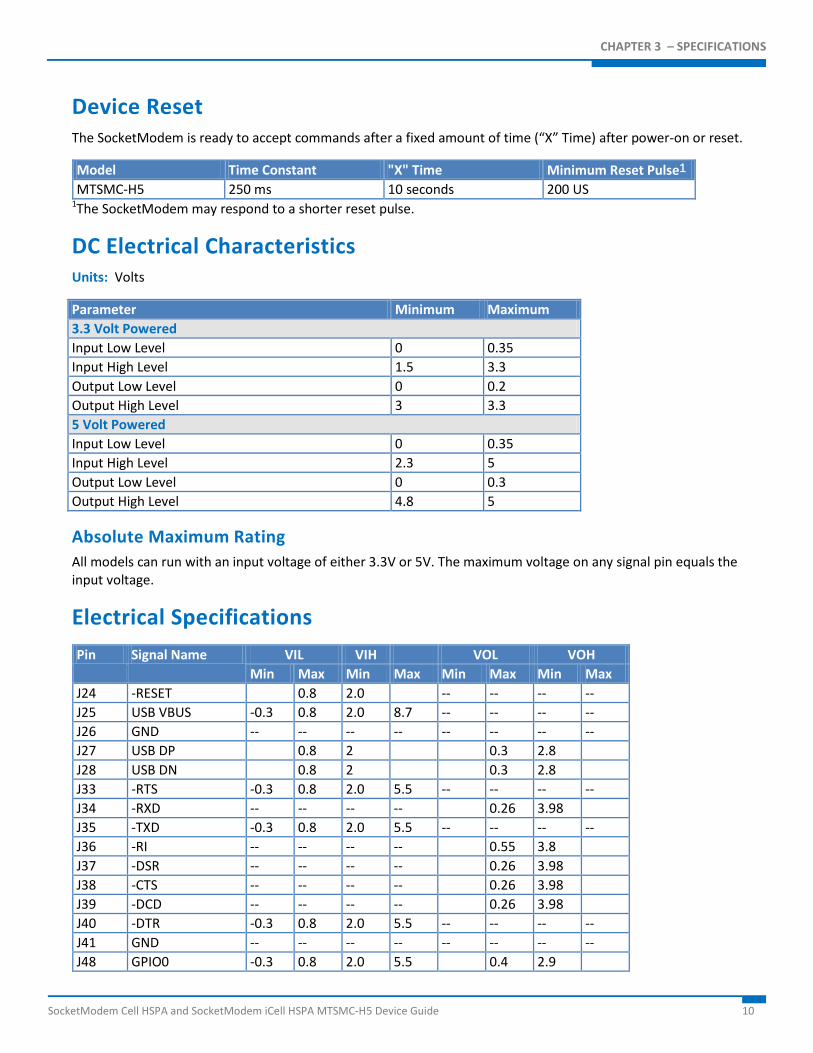
Device Reset The SocketModem is ready to accept commands after a fixed amount of time (“X” Time) after power-on or reset.
Model Time Constant "X" Time Minimum Reset Pulse1 MTSMC-H5 250 ms 10 seconds 200 US
1The SocketModem may respond to a shorter reset pulse.
DC Electrical Characteristics Units: Volts
Parameter Minimum Maximum 3.3 Volt Powered Input Low Level 0 0.35 Input High Level 1.5 3.3 Output Low Level 0 0.2 Output High Level 3 3.3 5 Volt Powered Input Low Level 0 0.35 Input High Level 2.3 5 Output Low Level 0 0.3 Output High Level 4.8 5
Absolute Maximum Rating All models can run with an input voltage of either 3.3V or 5V. The maximum voltage on any signal pin equals the input voltage.
Electrical Specifications
Pin Signal Name VIL VIH VOL VOH Min Max Min Max Min Max Min Max
J24 -RESET 0.8 2.0 -- -- -- -- J25 USB VBUS -0.3 0.8 2.0 8.7 -- -- -- -- J26 GND -- -- -- -- -- -- -- -- J27 USB DP 0.8 2 0.3 2.8 J28 USB DN 0.8 2 0.3 2.8 J33 -RTS -0.3 0.8 2.0 5.5 -- -- -- -- J34 -RXD -- -- -- -- 0.26 3.98 J35 -TXD -0.3 0.8 2.0 5.5 -- -- -- -- J36 -RI -- -- -- -- 0.55 3.8 J37 -DSR -- -- -- -- 0.26 3.98 J38 -CTS -- -- -- -- 0.26 3.98 J39 -DCD -- -- -- -- 0.26 3.98 J40 -DTR -0.3 0.8 2.0 5.5 -- -- -- -- J41 GND -- -- -- -- -- -- -- -- J48 GPIO0 -0.3 0.8 2.0 5.5 0.4 2.9
CHAPTER 3 – SPECIFICATIONS
11 SocketModem Cell HSPA and SocketModem iCell HSPA MTSMC-H5 Device Guide
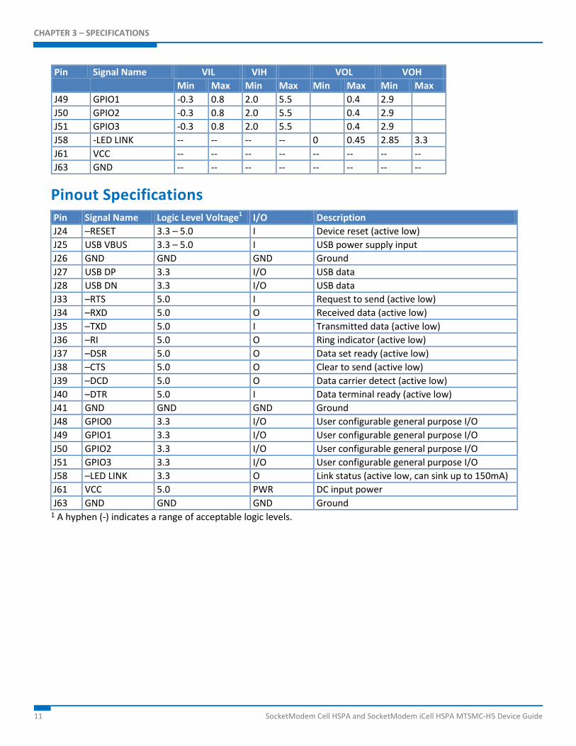
Pin Signal Name VIL VIH VOL VOH Min Max Min Max Min Max Min Max
J49 GPIO1 -0.3 0.8 2.0 5.5 0.4 2.9 J50 GPIO2 -0.3 0.8 2.0 5.5 0.4 2.9 J51 GPIO3 -0.3 0.8 2.0 5.5 0.4 2.9 J58 -LED LINK -- -- -- -- 0 0.45 2.85 3.3 J61 VCC -- -- -- -- -- -- -- -- J63 GND -- -- -- -- -- -- -- --
Pinout Specifications Pin Signal Name Logic Level Voltage1 I/O Description J24 –RESET 3.3 – 5.0 I Device reset (active low) J25 USB VBUS 3.3 – 5.0 I USB power supply input J26 GND GND GND Ground J27 USB DP 3.3 I/O USB data J28 USB DN 3.3 I/O USB data J33 –RTS 5.0 I Request to send (active low) J34 –RXD 5.0 O Received data (active low) J35 –TXD 5.0 I Transmitted data (active low) J36 –RI 5.0 O Ring indicator (active low) J37 –DSR 5.0 O Data set ready (active low) J38 –CTS 5.0 O Clear to send (active low) J39 –DCD 5.0 O Data carrier detect (active low) J40 –DTR 5.0 I Data terminal ready (active low) J41 GND GND GND Ground J48 GPIO0 3.3 I/O User configurable general purpose I/O J49 GPIO1 3.3 I/O User configurable general purpose I/O J50 GPIO2 3.3 I/O User configurable general purpose I/O J51 GPIO3 3.3 I/O User configurable general purpose I/O J58 –LED LINK 3.3 O Link status (active low, can sink up to 150mA) J61 VCC 5.0 PWR DC input power J63 GND GND GND Ground
1 A hyphen (-) indicates a range of acceptable logic levels.
CHAPTER 3 – SPECIFICATIONS
SocketModem Cell HSPA and SocketModem iCell HSPA MTSMC-H5 Device Guide 12
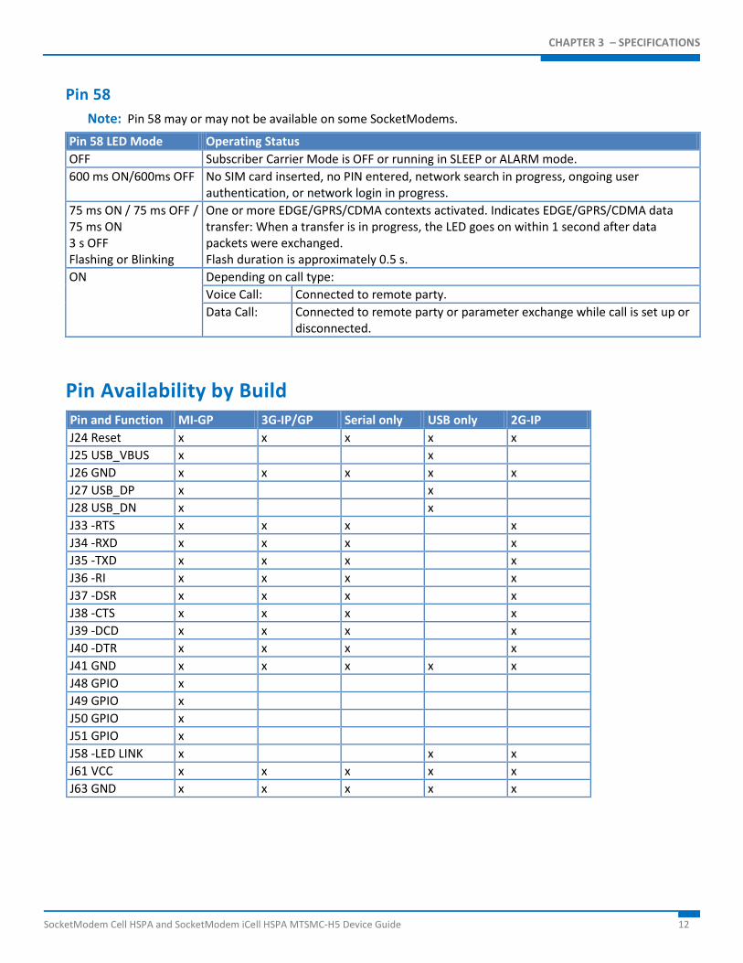
Pin 58 Note: Pin 58 may or may not be available on some SocketModems.
Pin 58 LED Mode Operating Status OFF Subscriber Carrier Mode is OFF or running in SLEEP or ALARM mode. 600 ms ON/600ms OFF No SIM card inserted, no PIN entered, network search in progress, ongoing user
authentication, or network login in progress. 75 ms ON / 75 ms OFF / 75 ms ON 3 s OFF Flashing or Blinking
One or more EDGE/GPRS/CDMA contexts activated. Indicates EDGE/GPRS/CDMA data transfer: When a transfer is in progress, the LED goes on within 1 second after data packets were exchanged. Flash duration is approximately 0.5 s.
ON Depending on call type: Voice Call: Connected to remote party. Data Call: Connected to remote party or parameter exchange while call is set up or
disconnected.
Pin Availability by Build Pin and Function MI-GP 3G-IP/GP Serial only USB only 2G-IP J24 Reset x x x x x J25 USB_VBUS x x J26 GND x x x x x J27 USB_DP x x J28 USB_DN x x J33 -RTS x x x x J34 -RXD x x x x J35 -TXD x x x x J36 -RI x x x x J37 -DSR x x x x J38 -CTS x x x x J39 -DCD x x x x J40 -DTR x x x x J41 GND x x x x x J48 GPIO x J49 GPIO x J50 GPIO x J51 GPIO x J58 -LED LINK x x x J61 VCC x x x x x J63 GND x x x x x
CHAPTER 3 – SPECIFICATIONS
13 SocketModem Cell HSPA and SocketModem iCell HSPA MTSMC-H5 Device Guide
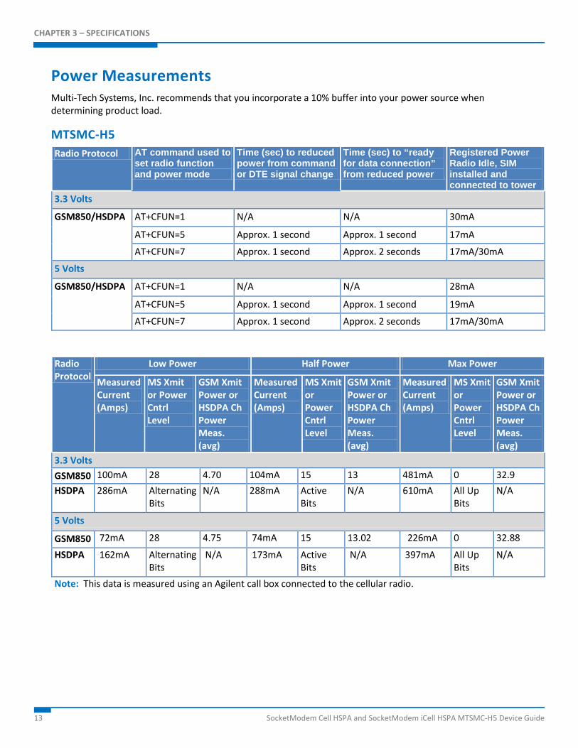
Power Measurements Multi-Tech Systems, Inc. recommends that you incorporate a 10% buffer into your power source when determining product load.
MTSMC-H5 Radio Protocol AT command used to
set radio function and power mode
Time (sec) to reduced power from command or DTE signal change
Time (sec) to “ready for data connection” from reduced power
Registered Power Radio Idle, SIM installed and connected to tower
3.3 Volts
GSM850/HSDPA AT+CFUN=1 N/A N/A 30mA
AT+CFUN=5 Approx. 1 second Approx. 1 second 17mA
AT+CFUN=7 Approx. 1 second Approx. 2 seconds 17mA/30mA
5 Volts
GSM850/HSDPA AT+CFUN=1 N/A N/A 28mA
AT+CFUN=5 Approx. 1 second Approx. 1 second 19mA
AT+CFUN=7 Approx. 1 second Approx. 2 seconds 17mA/30mA
Radio Protocol
Low Power Half Power Max Power
Measured Current (Amps)
MS Xmit or Power Cntrl Level
GSM Xmit Power or HSDPA Ch Power Meas. (avg)
Measured Current (Amps)
MS Xmit or Power Cntrl Level
GSM Xmit Power or HSDPA Ch Power Meas. (avg)
Measured Current (Amps)
MS Xmit or Power Cntrl Level
GSM Xmit Power or HSDPA Ch Power Meas. (avg)
3.3 Volts GSM850 100mA 28 4.70 104mA 15 13 481mA 0 32.9 HSDPA 286mA Alternating
Bits N/A 288mA Active
Bits N/A 610mA All Up
Bits N/A
5 Volts
GSM850 72mA 28 4.75 74mA 15 13.02 226mA 0 32.88
HSDPA 162mA Alternating Bits
N/A 173mA Active Bits
N/A 397mA All Up Bits
N/A
Note: This data is measured using an Agilent call box connected to the cellular radio.
CHAPTER 3 – SPECIFICATIONS
SocketModem Cell HSPA and SocketModem iCell HSPA MTSMC-H5 Device Guide 14
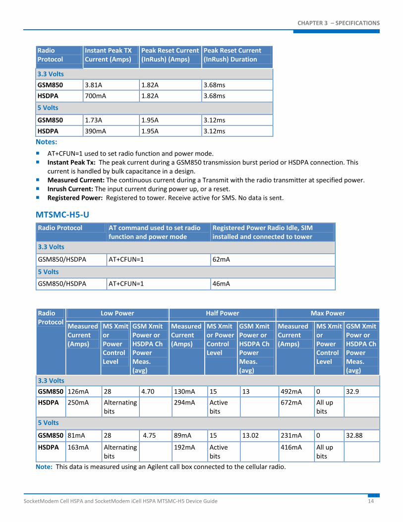
Radio Protocol
Instant Peak TX Current (Amps)
Peak Reset Current (InRush) (Amps)
Peak Reset Current (InRush) Duration
3.3 Volts GSM850 3.81A 1.82A 3.68ms HSDPA 700mA 1.82A 3.68ms
5 Volts
GSM850 1.73A 1.95A 3.12ms HSDPA 390mA 1.95A 3.12ms
Notes: AT+CFUN=1 used to set radio function and power mode. Instant Peak Tx: The peak current during a GSM850 transmission burst period or HSDPA connection. This
current is handled by bulk capacitance in a design. Measured Current: The continuous current during a Transmit with the radio transmitter at specified power. Inrush Current: The input current during power up, or a reset. Registered Power: Registered to tower. Receive active for SMS. No data is sent.
MTSMC-H5-U Radio Protocol AT command used to set radio
function and power mode Registered Power Radio Idle, SIM installed and connected to tower
3.3 Volts
GSM850/HSDPA AT+CFUN=1 62mA
5 Volts
GSM850/HSDPA AT+CFUN=1 46mA
Radio Protocol
Low Power Half Power Max Power
Measured Current (Amps)
MS Xmit or Power Control Level
GSM Xmit Power or HSDPA Ch Power Meas. (avg)
Measured Current (Amps)
MS Xmit or Power Control Level
GSM Xmit Power or HSDPA Ch Power Meas. (avg)
Measured Current (Amps)
MS Xmit or Power Control Level
GSM Xmit Powr or HSDPA Ch Power Meas. (avg)
3.3 Volts GSM850 126mA 28 4.70 130mA 15 13 492mA 0 32.9 HSDPA 250mA Alternating
bits 294mA Active
bits 672mA All up
bits
5 Volts
GSM850 81mA 28 4.75 89mA 15 13.02 231mA 0 32.88
HSDPA 163mA Alternating bits
192mA Active bits
416mA All up bits
Note: This data is measured using an Agilent call box connected to the cellular radio.
CHAPTER 3 – SPECIFICATIONS
15 SocketModem Cell HSPA and SocketModem iCell HSPA MTSMC-H5 Device Guide
Radio Protocol
Instant Peak TX Current (Amps)
Peak Reset Current (InRush) (Amps)
Peak Reset Current (InRush) Duration
3.3 Volts GSM850 3.53A 2.14A 4.80ms HSDPA 620mA 2.14A 4.80ms
5 Volts
GSM850 1.48A 2.11A 3.00ms HSDPA 407mA 2.11A 3.00ms
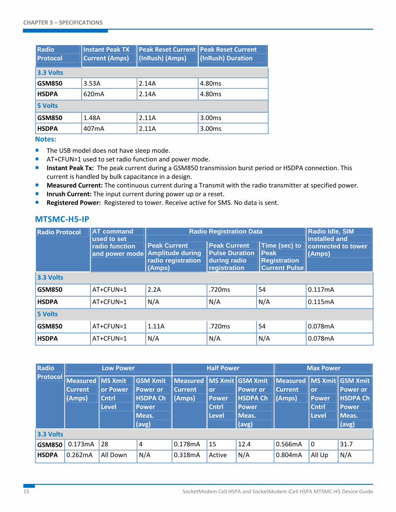
Notes: The USB model does not have sleep mode. AT+CFUN=1 used to set radio function and power mode. Instant Peak Tx: The peak current during a GSM850 transmission burst period or HSDPA connection. This
current is handled by bulk capacitance in a design. Measured Current: The continuous current during a Transmit with the radio transmitter at specified power. Inrush Current: The input current during power up or a reset. Registered Power: Registered to tower. Receive active for SMS. No data is sent.
MTSMC-H5-IP Radio Protocol AT command
used to set radio function and power mode
Radio Registration Data Radio Idle, SIM installed and connected to tower (Amps)
Peak Current Amplitude during radio registration (Amps)
Peak Current Pulse Duration during radio registration
Time (sec) to Peak Registration Current Pulse
3.3 Volts
GSM850 AT+CFUN=1 2.2A .720ms 54 0.117mA
HSDPA AT+CFUN=1 N/A N/A N/A 0.115mA
5 Volts
GSM850 AT+CFUN=1 1.11A .720ms 54 0.078mA
HSDPA AT+CFUN=1 N/A N/A N/A 0.078mA
Radio Protocol
Low Power Half Power Max Power
Measured Current (Amps)
MS Xmit or Power Cntrl Level
GSM Xmit Power or HSDPA Ch Power Meas. (avg)
Measured Current (Amps)
MS Xmit or Power Cntrl Level
GSM Xmit Power or HSDPA Ch Power Meas. (avg)
Measured Current (Amps)
MS Xmit or Power Cntrl Level
GSM Xmit Power or HSDPA Ch Power Meas. (avg)
3.3 Volts GSM850 0.173mA 28 4 0.178mA 15 12.4 0.566mA 0 31.7 HSDPA 0.262mA All Down N/A 0.318mA Active N/A 0.804mA All Up N/A
CHAPTER 3 – SPECIFICATIONS
SocketModem Cell HSPA and SocketModem iCell HSPA MTSMC-H5 Device Guide 16
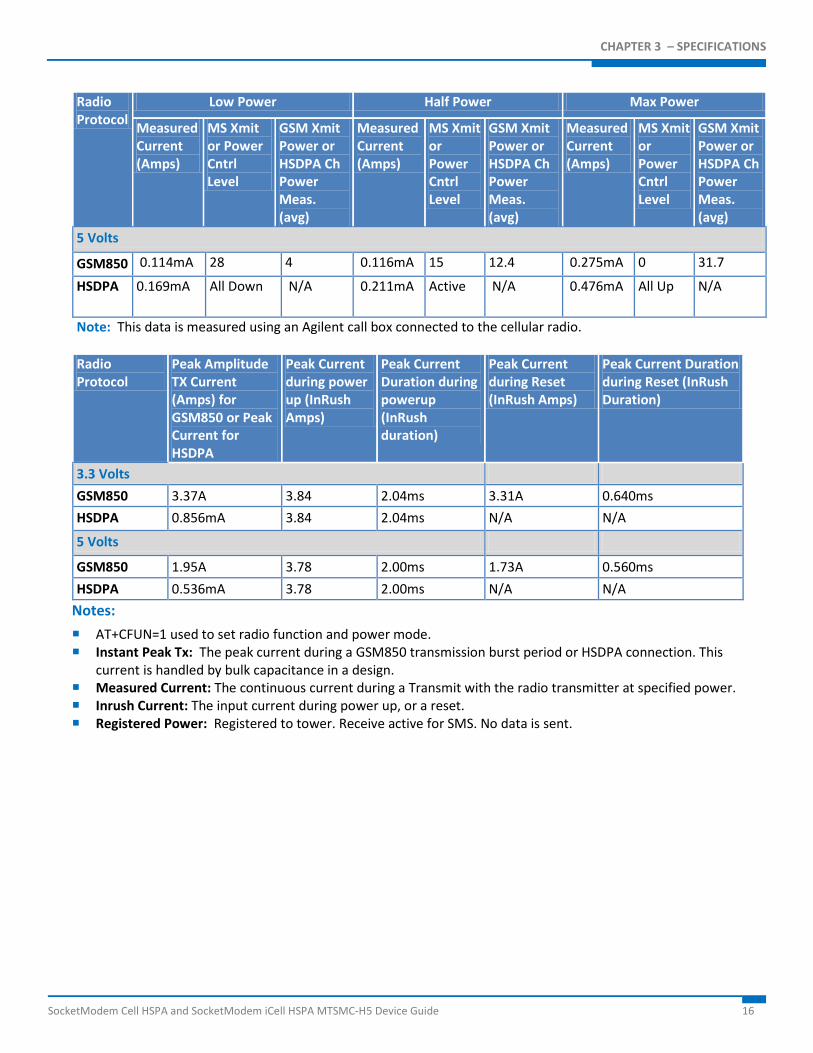
Radio Protocol
Low Power Half Power Max Power
Measured Current (Amps)
MS Xmit or Power Cntrl Level
GSM Xmit Power or HSDPA Ch Power Meas. (avg)
Measured Current (Amps)
MS Xmit or Power Cntrl Level
GSM Xmit Power or HSDPA Ch Power Meas. (avg)
Measured Current (Amps)
MS Xmit or Power Cntrl Level
GSM Xmit Power or HSDPA Ch Power Meas. (avg)
5 Volts
GSM850 0.114mA 28 4 0.116mA 15 12.4 0.275mA 0 31.7
HSDPA 0.169mA All Down N/A 0.211mA Active N/A 0.476mA All Up N/A
Note: This data is measured using an Agilent call box connected to the cellular radio.
Radio Protocol
Peak Amplitude TX Current (Amps) for GSM850 or Peak Current for HSDPA
Peak Current during power up (InRush Amps)
Peak Current Duration during powerup (InRush duration)
Peak Current during Reset (InRush Amps)
Peak Current Duration during Reset (InRush Duration)
3.3 Volts GSM850 3.37A 3.84 2.04ms 3.31A 0.640ms HSDPA 0.856mA 3.84 2.04ms N/A N/A
5 Volts
GSM850 1.95A 3.78 2.00ms 1.73A 0.560ms HSDPA 0.536mA 3.78 2.00ms N/A N/A
Notes: AT+CFUN=1 used to set radio function and power mode. Instant Peak Tx: The peak current during a GSM850 transmission burst period or HSDPA connection. This
current is handled by bulk capacitance in a design. Measured Current: The continuous current during a Transmit with the radio transmitter at specified power. Inrush Current: The input current during power up, or a reset. Registered Power: Registered to tower. Receive active for SMS. No data is sent.
CHAPTER 3 – SPECIFICATIONS
17 SocketModem Cell HSPA and SocketModem iCell HSPA MTSMC-H5 Device Guide
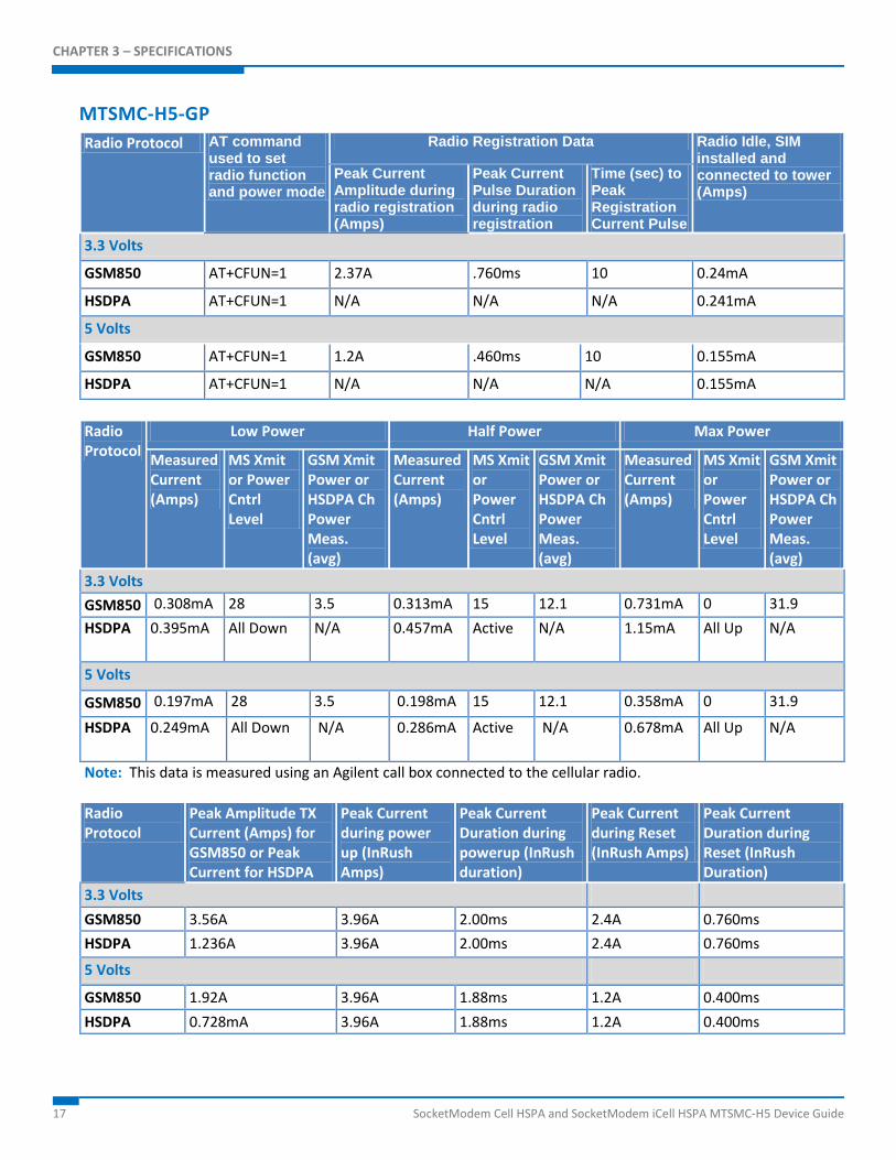
MTSMC-H5-GP Radio Protocol AT command
used to set radio function and power mode
Radio Registration Data Radio Idle, SIM installed and connected to tower (Amps)
Peak Current Amplitude during radio registration (Amps)
Peak Current Pulse Duration during radio registration
Time (sec) to Peak Registration Current Pulse
3.3 Volts
GSM850 AT+CFUN=1 2.37A .760ms 10 0.24mA
HSDPA AT+CFUN=1 N/A N/A N/A 0.241mA
5 Volts
GSM850 AT+CFUN=1 1.2A .460ms 10 0.155mA
HSDPA AT+CFUN=1 N/A N/A N/A 0.155mA
Radio Protocol
Low Power Half Power Max Power
Measured Current (Amps)
MS Xmit or Power Cntrl Level
GSM Xmit Power or HSDPA Ch Power Meas. (avg)
Measured Current (Amps)
MS Xmit or Power Cntrl Level
GSM Xmit Power or HSDPA Ch Power Meas. (avg)
Measured Current (Amps)
MS Xmit or Power Cntrl Level
GSM Xmit Power or HSDPA Ch Power Meas. (avg)
3.3 Volts GSM850 0.308mA 28 3.5 0.313mA 15 12.1 0.731mA 0 31.9 HSDPA 0.395mA All Down N/A 0.457mA Active N/A 1.15mA All Up N/A
5 Volts
GSM850 0.197mA 28 3.5 0.198mA 15 12.1 0.358mA 0 31.9
HSDPA 0.249mA All Down N/A 0.286mA Active N/A 0.678mA All Up N/A
Note: This data is measured using an Agilent call box connected to the cellular radio.
Radio Protocol
Peak Amplitude TX Current (Amps) for GSM850 or Peak Current for HSDPA
Peak Current during power up (InRush Amps)
Peak Current Duration during powerup (InRush duration)
Peak Current during Reset (InRush Amps)
Peak Current Duration during Reset (InRush Duration)
3.3 Volts GSM850 3.56A 3.96A 2.00ms 2.4A 0.760ms HSDPA 1.236A 3.96A 2.00ms 2.4A 0.760ms
5 Volts
GSM850 1.92A 3.96A 1.88ms 1.2A 0.400ms HSDPA 0.728mA 3.96A 1.88ms 1.2A 0.400ms
CHAPTER 3 – SPECIFICATIONS
SocketModem Cell HSPA and SocketModem iCell HSPA MTSMC-H5 Device Guide 18
Notes: AT+CFUN=1 used to set radio function and power mode. Instant Peak Tx: The peak current during a GSM850 transmission burst period or HSDPA connection. This
current is handled by bulk capacitance in a design. Measured Current: The continuous current during a Transmit with the radio transmitter at specified power. Inrush Current: The input current during power up, or a reset. Registered Power: Registered to tower. Receive active for SMS. No data is sent.
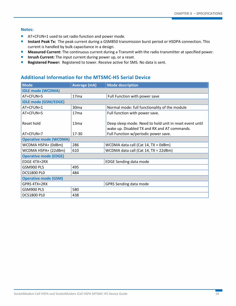
Additional Information for the MTSMC-H5 Serial Device Mode Average (mA) Mode description IDLE mode (WCDMA) AT+CFUN=5 17ma Full Function with power save IDLE mode (GSM/EDGE) AT+CFUN=1 30ma Normal mode: full functionality of the module AT+CFUN=5 Reset hold AT+CFUN=7
17ma 13ma 17-30
Full function with power save. Deep sleep mode. Need to hold unit in reset event until wake up. Disabled TX and RX and AT commands. Full Function w/periodic power save.
Operative mode (WCDMA) WCDMA HSPA+ (0dBm) 286 WCDMA data call (Cat 14, TX = 0dBm) WCDMA HSPA+ (22dBm) 610 WCDMA data call (Cat 14, TX = 22dBm) Operative mode (EDGE) EDGE 4TX+2RX EDGE Sending data mode GSM900 PL5 495 DCS1800 PL0 484 Operative mode (GSM) GPRS 4TX+2RX GPRS Sending data mode GSM900 PL5 580 DCS1800 PL0 438
CHAPTER 3 – SPECIFICATIONS
19 SocketModem Cell HSPA and SocketModem iCell HSPA MTSMC-H5 Device Guide
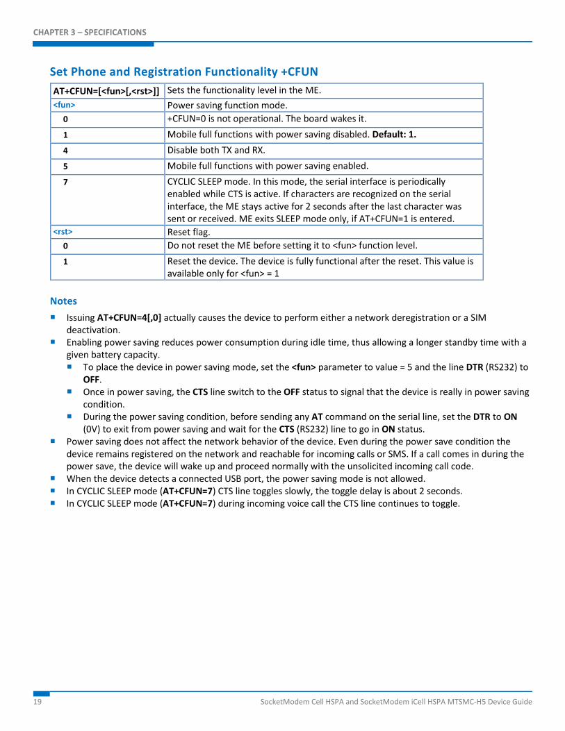
Set Phone and Registration Functionality +CFUN AT+CFUN=[<fun>[,<rst>]] Sets the functionality level in the ME. <fun> Power saving function mode.
0 +CFUN=0 is not operational. The board wakes it. 1 Mobile full functions with power saving disabled. Default: 1. 4 Disable both TX and RX. 5 Mobile full functions with power saving enabled. 7 CYCLIC SLEEP mode. In this mode, the serial interface is periodically
enabled while CTS is active. If characters are recognized on the serial interface, the ME stays active for 2 seconds after the last character was sent or received. ME exits SLEEP mode only, if AT+CFUN=1 is entered.
<rst> Reset flag. 0 Do not reset the ME before setting it to <fun> function level. 1 Reset the device. The device is fully functional after the reset. This value is
available only for <fun> = 1 Notes Issuing AT+CFUN=4[,0] actually causes the device to perform either a network deregistration or a SIM
deactivation. Enabling power saving reduces power consumption during idle time, thus allowing a longer standby time with a
given battery capacity. To place the device in power saving mode, set the <fun> parameter to value = 5 and the line DTR (RS232) to
OFF. Once in power saving, the CTS line switch to the OFF status to signal that the device is really in power saving
condition. During the power saving condition, before sending any AT command on the serial line, set the DTR to ON
(0V) to exit from power saving and wait for the CTS (RS232) line to go in ON status. Power saving does not affect the network behavior of the device. Even during the power save condition the
device remains registered on the network and reachable for incoming calls or SMS. If a call comes in during the power save, the device will wake up and proceed normally with the unsolicited incoming call code.
When the device detects a connected USB port, the power saving mode is not allowed. In CYCLIC SLEEP mode (AT+CFUN=7) CTS line toggles slowly, the toggle delay is about 2 seconds. In CYCLIC SLEEP mode (AT+CFUN=7) during incoming voice call the CTS line continues to toggle.
CHAPTER 3 – SPECIFICATIONS
SocketModem Cell HSPA and SocketModem iCell HSPA MTSMC-H5 Device Guide 20
GSM Power Saving Modes for Serial Devices The H5 serial devices provide a function that reduces the power consumption when they are in IDLE state (waiting for a call), allowing a longer activity with a given battery capacity. You can configure the power saving function in several modes as needed.
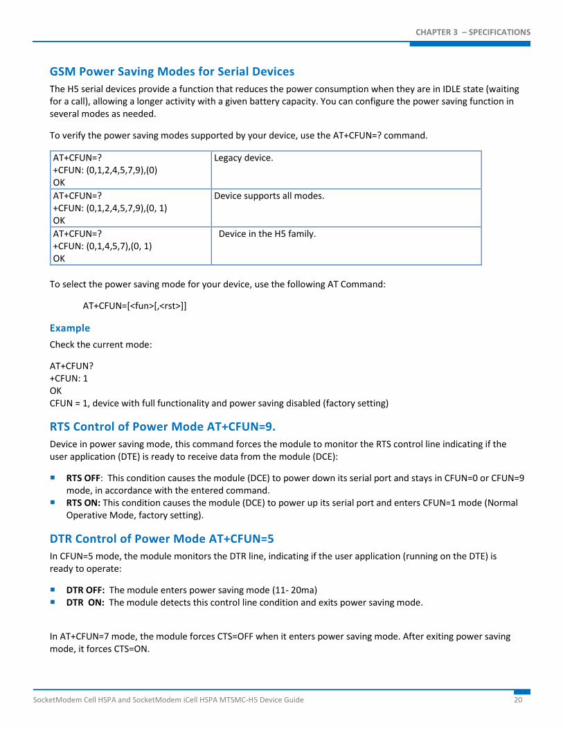
To verify the power saving modes supported by your device, use the AT+CFUN=? command.
AT+CFUN=? +CFUN: (0,1,2,4,5,7,9),(0) OK
Legacy device.
AT+CFUN=? +CFUN: (0,1,2,4,5,7,9),(0, 1) OK
Device supports all modes.
AT+CFUN=? +CFUN: (0,1,4,5,7),(0, 1) OK
Device in the H5 family.
To select the power saving mode for your device, use the following AT Command:
AT+CFUN=[<fun>[,<rst>]]
Example Check the current mode:
AT+CFUN? +CFUN: 1 OK CFUN = 1, device with full functionality and power saving disabled (factory setting)
RTS Control of Power Mode AT+CFUN=9. Device in power saving mode, this command forces the module to monitor the RTS control line indicating if the user application (DTE) is ready to receive data from the module (DCE):
RTS OFF: This condition causes the module (DCE) to power down its serial port and stays in CFUN=0 or CFUN=9 mode, in accordance with the entered command.
RTS ON: This condition causes the module (DCE) to power up its serial port and enters CFUN=1 mode (Normal Operative Mode, factory setting).
DTR Control of Power Mode AT+CFUN=5 In CFUN=5 mode, the module monitors the DTR line, indicating if the user application (running on the DTE) is ready to operate:
DTR OFF: The module enters power saving mode (11- 20ma) DTR ON: The module detects this control line condition and exits power saving mode.
In AT+CFUN=7 mode, the module forces CTS=OFF when it enters power saving mode. After exiting power saving mode, it forces CTS=ON.
CHAPTER 3 – SPECIFICATIONS
21 SocketModem Cell HSPA and SocketModem iCell HSPA MTSMC-H5 Device Guide
CTS control line indicates permission from the DCE for the DTE to send data to the DCE. When the module is not ready to receive data (e.g.: commands) it ties up the CTS line, when it is ready to receive data it ties down the CTS line. The user application can monitor the CTS control line to check if the module is ready for commands, in accordance with V.24 Standard
Notes When the module is powered ON the power saving function is disabled (CFUN=1, factory setting) in order to
guarantee the data exchange between the H5 device and the user device; for this reason the CFUN mode command should be entered after every power up.
The protocol implementation of the module requires a delay between consecutive activation of CFUN=1 and CFUN=4 (or vice versa) modes. It is suggested you use a delay of 10 sec.
The power saving function does not affect the network activity of the module. During the power saving mode the module remains registered on the network and reachable for incoming calls or SMS. If a call comes in during the power saving mode, the module will wake up and proceed normally with the unsolicited incoming call code.
Assume that the module is in power saving mode. The paging time range is 0.5 - 2.1 sec, depending on DRX time set by network. When the module wakes up from the power saving mode, it takes a maximum of 150 ms before checking the DTR line coming from the DTE. If a command is received during power saving, the module needs at least 0.5-2.1 sec +150 ms to be ready. Use a delay of at least 2250 ms between opening the port (DTR=ON) and sending commands.
CHAPTER 4 –DEVICE SPECIFIC REGULATORY INFORMATION
SocketModem Cell HSPA and SocketModem iCell HSPA MTSMC-H5 Device Guide 22
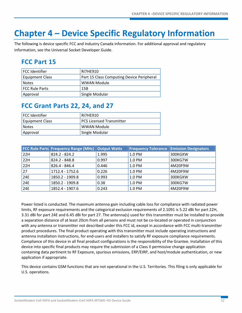
Chapter 4 – Device Specific Regulatory Information The following is device specific FCC and Industry Canada information. For additional approval and regulatory information, see the Universal Socket Developer Guide.
FCC Part 15 FCC Identifier RI7HE910 Equipment Class Part 15 Class Computing Device Peripheral Notes WWAN Module FCC Rule Parts 15B Approval Single Modular
FCC Grant Parts 22, 24, and 27 FCC Identifier RI7HE910 Equipment Class PCS Licensed Transmitter Notes WWAN Module Approval Single Modular
FCC Rule Parts Frequency Range (MHz) Output Watts Frequency Tolerance Emission Designators 22H 824.2 - 824.2 1.995 1.0 PM 300KGXW 22H 824.2 - 848.8 0.997 1.0 PM 300KG7W 22H 826.4 - 846.4 0.446 1.0 PM 4M20F9W 27 1712.4 - 1752.6 0.226 1.0 PM 4M20F9W 24E 1850.2 - 1909.8 0.993 1.0 PM 300KGXW 24E 1850.2 - 1909.8 0.38 1.0 PM 300KG7W 24E 1852.4 - 1907.6 0.243 1.0 PM 4M20F9W
Power listed is conducted. The maximum antenna gain including cable loss for compliance with radiated power limits, RF exposure requirements and the categorical exclusion requirements of 2.1091 is 5.22 dBi for part 22H, 3.31 dBi for part 24E and 6.45 dBi for part 27. The antenna(s) used for this transmitter must be installed to provide a separation distance of at least 20cm from all persons and must not be co-located or operated in conjunction with any antenna or transmitter not described under this FCC id, except in accordance with FCC multi-transmitter product procedures. The final product operating with this transmitter must include operating instructions and antenna installation instructions, for end-users and installers to satisfy RF exposure compliance requirements. Compliance of this device in all final product configurations is the responsibility of the Grantee. Installation of this device into specific final products may require the submission of a Class II permissive change application containing data pertinent to RF Exposure, spurious emissions, ERP/EIRP, and host/module authentication, or new application if appropriate.
This device contains GSM functions that are not operational in the U.S. Territories. This filing is only applicable for U.S. operations.
CHAPTER 4 –FCC AND INDUSTRY CANADA INFORMATION
23 SocketModem Cell HSPA and SocketModem iCell HSPA MTSMC-H5 Device Guide
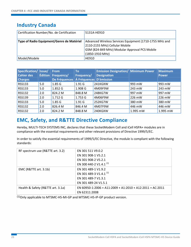
Industry Canada Certification Number/No. de Certification
5131A-HE910
Type of Radio Equipment/Genre de Matériel Advanced Wireless Services Equipment (1710-1755 MHz and 2110-2155 MHz) Cellular Mobile GSM (824-849 MHz) Modular Approval PCS Mobile (1850-1910 MHz)
Model/Modele HE910
Specification/ Cahier des Charges
Issue/ Édition
From Frequency/ De Fréquences
To Frequency/ Á Fréquences
Emission Designation/ Designation D’émission
Minimum Power Maximum Power
RSS133 5.0 1.85 G 1.91 G 241KGXW 993 mW 993 mW RSS133 5.0 1.852 G 1.908 G 4M09F9W 243 mW 243 mW RSS132 2.0 824.2 M 848.8 M 248KG7W 997 mW 997 mW RSS139 2.0 1.712 G 1.753 G 4M06F9W 226 mW 226 mW RSS133 5.0 1.85 G 1.91 G 252KG7W 380 mW 380 mW RSS132 2.0 826.4 M 846.4 M 4M07F9W 446 mW 446 mW RSS132 2.0 824.2 M 848.8 M 240KGXW 1.995 mW 1.995 mW
EMC, Safety, and R&TTE Directive Compliance Hereby, MULTI-TECH SYSTEMS INC, declares that these SocketModem Cell and iCell HSPA+ modules are in compliance with the essential requirements and other relevant provisions of Directive 1999/5/EC.
In order to satisfy the essential requirements of 1999/5/EC Directive, the module is compliant with the following standards:
RF spectrum use (R&TTE art. 3.2) EN 301 511 V9.0.2 EN 301 908-1 V5.2.1 EN 301 908-2 V5.2.1 EN 300 440-2 V1.4.1 (1)
EMC (R&TTE art. 3.1b) EN 301 489-1 V1.9.2 EN 301 489-3 V1.4.1 (1) EN 301 489-7 V1.3.1 EN 301 489-24 V1.5.1
Health & Safety (R&TTE art. 3.1a) EN 60950-1:2006 + A11:2009 + A1:2010 + A12:2011 + AC:2011 EN 62311:2008
(1)Only applicable to MTSMC-H5-MI-GP and MTSMC-H5-IP-GP product version.
CHAPTER 4 –DEVICE SPECIFIC REGULATORY INFORMATION
SocketModem Cell HSPA and SocketModem iCell HSPA MTSMC-H5 Device Guide 24
The conformity assessment procedure referred to in Article 10 and detailed in Annex IV of Directive 1995/5/EC has been followed with the involvement of the following Notified Body:
AT4 wireless, S.A. Parque Tecnologico de Andalucía C/ Severo Ochoa 2 295990 Campanillas – Málaga SPAIN Notified Body No: 1909
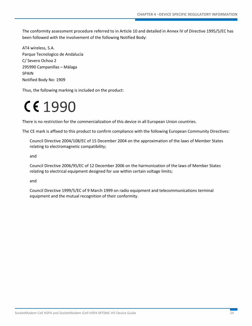
Thus, the following marking is included on the product:
There is no restriction for the commercialization of this device in all European Union countries.
The CE mark is affixed to this product to confirm compliance with the following European Community Directives:
Council Directive 2004/108/EC of 15 December 2004 on the approximation of the laws of Member States relating to electromagnetic compatibility;
and
Council Directive 2006/95/EC of 12 December 2006 on the harmonization of the laws of Member States relating to electrical equipment designed for use within certain voltage limits;
and
Council Directive 1999/5/EC of 9 March 1999 on radio equipment and telecommunications terminal equipment and the mutual recognition of their conformity.
CHAPTER 5 –APPLICATION NOTES
25 SocketModem Cell HSPA and SocketModem iCell HSPA MTSMC-H5 Device Guide
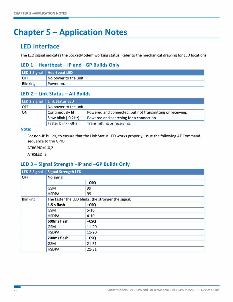
Chapter 5 – Application Notes LED Interface The LED signal indicates the SocketModem working status. Refer to the mechanical drawing for LED locations.
LED 1 – Heartbeat – IP and –GP Builds Only LED 1 Signal Heartbeat LED OFF No power to the unit. Blinking Power on.
LED 2 – Link Status – All Builds LED 2 Signal Link Status LED OFF No power to the unit. ON Continuously lit Powered and connected, but not transmitting or receiving.
Slow blink (-0.2Hz) Powered and searching for a connection. Faster blink (-3Hz) Transmitting or receiving.
Note: For non-IP builds, to ensure that the Link Status LED works properly, issue the following AT Command sequence to the GPIO: AT#GPIO=1,0,2 AT#SLED=2
LED 3 – Signal Strength –IP and –GP Builds Only LED 3 Signal Signal Strength LED OFF No signal.
+CSQ GSM 99 HSDPA 99
Blinking The faster the LED blinks, the stronger the signal. 1.5 s flash +CSQ GSM 5-10 HSDPA 4-10 600ms flash +CSQ GSM 11-20 HSDPA 11-20 200ms flash +CSQ GSM 21-31 HSDPA 21-31
CHAPTER 5 –APPLICATION NOTES
SocketModem Cell HSPA and SocketModem iCell HSPA MTSMC-H5 Device Guide 26
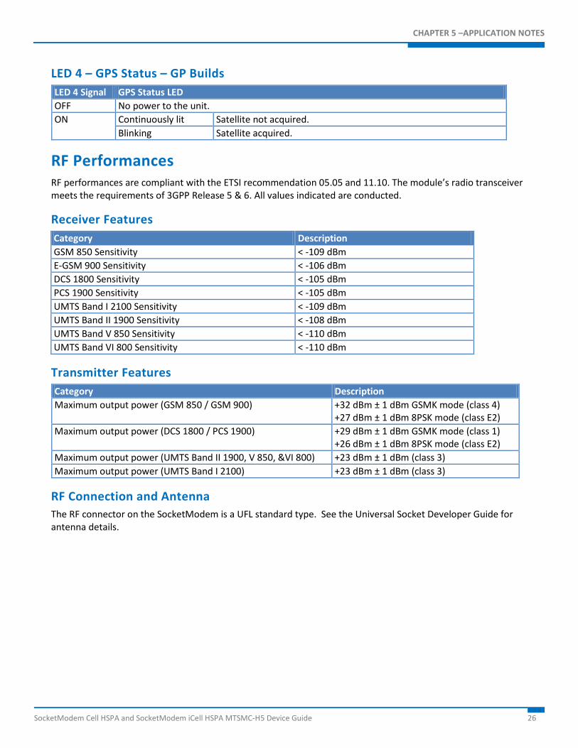
LED 4 – GPS Status – GP Builds LED 4 Signal GPS Status LED OFF No power to the unit. ON Continuously lit Satellite not acquired.
Blinking Satellite acquired.
RF Performances RF performances are compliant with the ETSI recommendation 05.05 and 11.10. The module’s radio transceiver meets the requirements of 3GPP Release 5 & 6. All values indicated are conducted.
Receiver Features Category Description GSM 850 Sensitivity < -109 dBm E-GSM 900 Sensitivity < -106 dBm DCS 1800 Sensitivity < -105 dBm PCS 1900 Sensitivity < -105 dBm UMTS Band I 2100 Sensitivity < -109 dBm UMTS Band II 1900 Sensitivity < -108 dBm UMTS Band V 850 Sensitivity < -110 dBm UMTS Band VI 800 Sensitivity < -110 dBm
Transmitter Features Category Description Maximum output power (GSM 850 / GSM 900) +32 dBm ± 1 dBm GSMK mode (class 4)
+27 dBm ± 1 dBm 8PSK mode (class E2) Maximum output power (DCS 1800 / PCS 1900) +29 dBm ± 1 dBm GSMK mode (class 1)
+26 dBm ± 1 dBm 8PSK mode (class E2) Maximum output power (UMTS Band II 1900, V 850, &VI 800) +23 dBm ± 1 dBm (class 3) Maximum output power (UMTS Band I 2100) +23 dBm ± 1 dBm (class 3)
RF Connection and Antenna The RF connector on the SocketModem is a UFL standard type. See the Universal Socket Developer Guide for antenna details.
CHAPTER 5 –APPLICATION NOTES
27 SocketModem Cell HSPA and SocketModem iCell HSPA MTSMC-H5 Device Guide
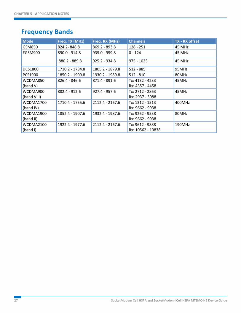
Frequency Bands Mode Freq. TX (MHz) Freq. RX (MHz) Channels TX - RX offset GSM850 824.2- 848.8 869.2 - 893.8 128 - 251 45 MHz EGSM900 890.0 - 914.8 935.0 - 959.8 0 - 124 45 MHz
880.2 - 889.8 925.2 - 934.8 975 - 1023 45 MHz
DCS1800 1710.2 - 1784.8 1805.2 - 1879.8 512 - 885 95MHz PCS1900 1850.2 - 1909.8 1930.2 - 1989.8 512 - 810 80MHz WCDMA850 (band V)
826.4 - 846.6 871.4 - 891.6 Tx: 4132 - 4233 Rx: 4357 - 4458
45MHz
WCDMA900 (band VIII)
882.4 - 912.6 927.4 - 957.6 Tx: 2712 - 2863 Rx: 2937 - 3088
45MHz
WCDMA1700 (band IV)
1710.4 - 1755.6 2112.4 - 2167.6 Tx: 1312 - 1513 Rx: 9662 - 9938
400MHz
WCDMA1900 (band II)
1852.4 - 1907.6 1932.4 - 1987.6 Tx: 9262 - 9538 Rx: 9662 - 9938
80MHz
WCDMA2100 (band I)
1922.4 - 1977.6 2112.4 - 2167.6 Tx: 9612 - 9888 Rx: 10562 - 10838
190MHz


