+ All Categories
Home > Documents > S~OF THE - Defense Technical Information Center irDveopen Center =75-P441 Warmirgton, DA 19897 WokUi...

S~OF THE - Defense Technical Information Center irDveopen Center =75-P441 Warmirgton, DA 19897 WokUi...

Date post: 27-May-2018
Category:
Upload: phamtram
View: 215 times
Download: 0 times
Share this document with a friend
112
It OS-137 AN ANALYTICAL AND EXPERIMENTAL INVESTIGATION 2• OF THE HOVERING DYNAMICS S~OF THE AEROCRANE HYBRID HEAVYLIFT VEHICLE ALL AMERICAN ENGINEERING COMPANY P.O. Box 1247 801 S. Madison St. Wilmington, DE 19899 June 1976 Final Report Approved for Public Release Distrilution Unlimited Prepared for: DEPARTMENT OF THE NAVY Naval Air Systems Command (03P32) Washington, D.C. 20361 DEPARTMENT OF THE NAVY Naval Air Development Center (31P3) Air Vehicle Technology Department Warminster, PA 18974 D Nov
Transcript

It

OS-137

AN ANALYTICAL AND EXPERIMENTAL INVESTIGATION

2• OF THE HOVERING DYNAMICS

S~OF THE

AEROCRANE HYBRID HEAVYLIFT VEHICLE

ALL AMERICAN ENGINEERING COMPANYP.O. Box 1247 801 S. Madison St.

Wilmington, DE 19899

June 1976

Final Report

Approved for Public Release

Distrilution Unlimited

Prepared for:

DEPARTMENT OF THE NAVYNaval Air Systems Command (03P32)Washington, D.C. 20361

DEPARTMENT OF THE NAVYNaval Air Development Center (31P3)Air Vehicle Technology Department

Warminster, PA 18974

D

Nov

D.ISCLAIME R

THIS DOCUMENT IS BEST

QUALIT'Y AVAILABLE. TIM COPY

FURNISHED TO DTIC CONTAINED

A SIGNIFICANT NUMBER OF

E 3 W'TV RJP CIRC14 DO NOT

REPRODUCED FROMBEST AVAILABLE COPY

U.NC IASSIFHILDI

SECU14ITY CLASSIFICATIO04 OF THIS PAGE (We Del.s P.Ivlred)

REPORT DOCUMENTATION PAGE BEFORE OPEINFR

I ~I REqF_%Lg_ VT ACENN,3RCPIENTS CATALOG NUMBFA

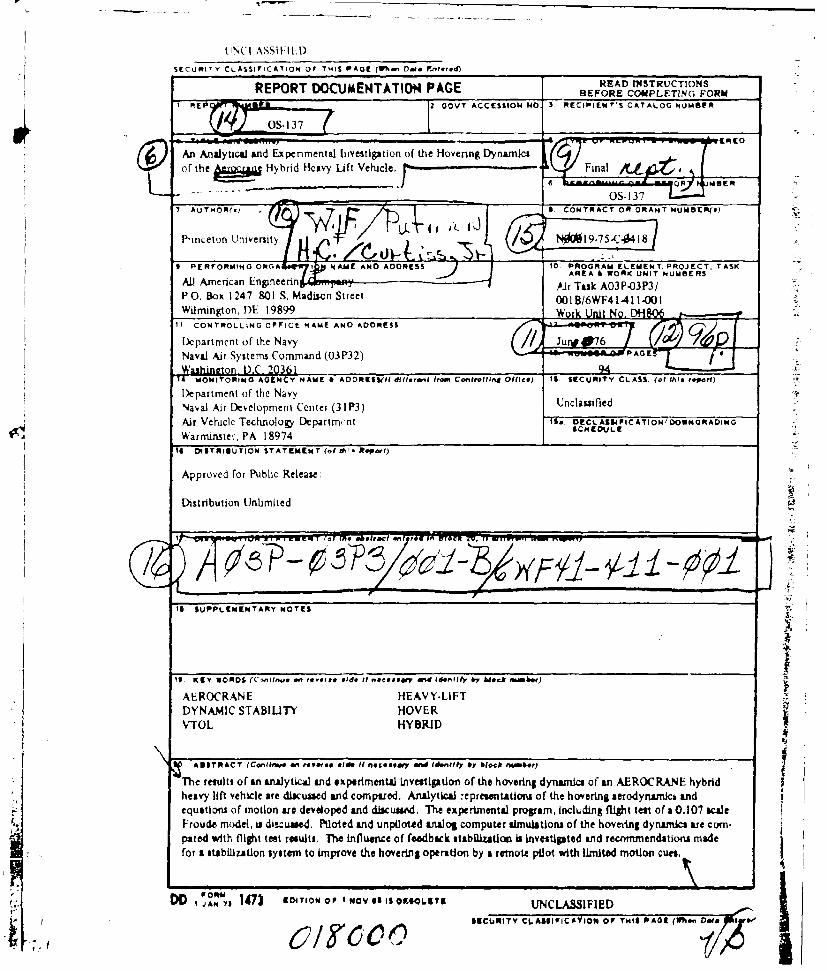
&An Analytical and Experimental hivestigation of the Hovering Dynamics

of t e A r c a e H y h n d H e a v y Lif t V e h ic le . F i n al

Naa AUTMR( Sys.m CoTmAnd OR RANP32)E~s

DPartmcent ofnhN Un lasiteNaa irDveopen Center =75-P441

Warmirgton, DA 19897 WokUi o£H0

Naa A~Tirugo SytemsCommnd (03P32 "*GA 7"'a

II

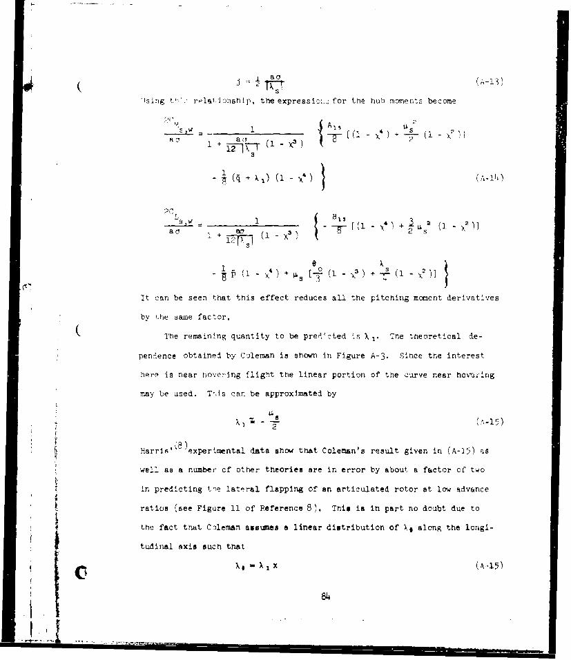
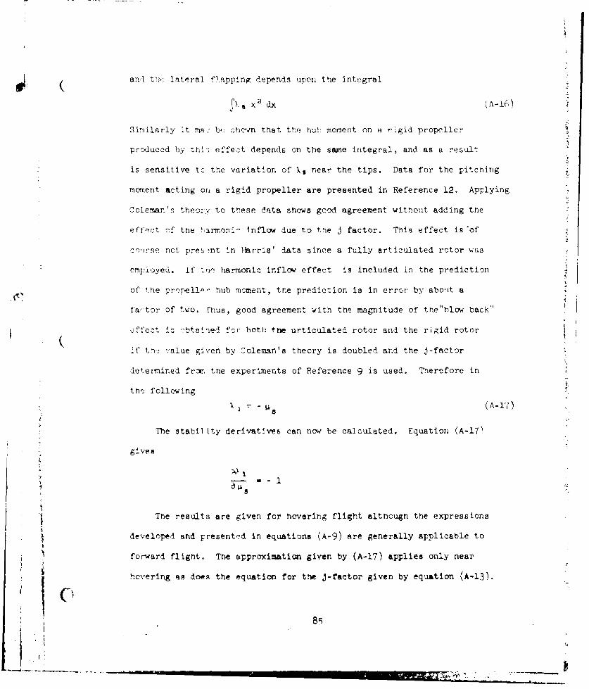
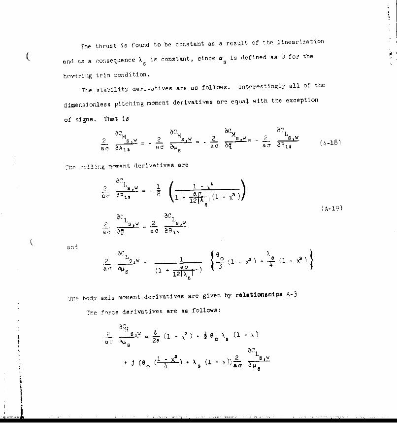
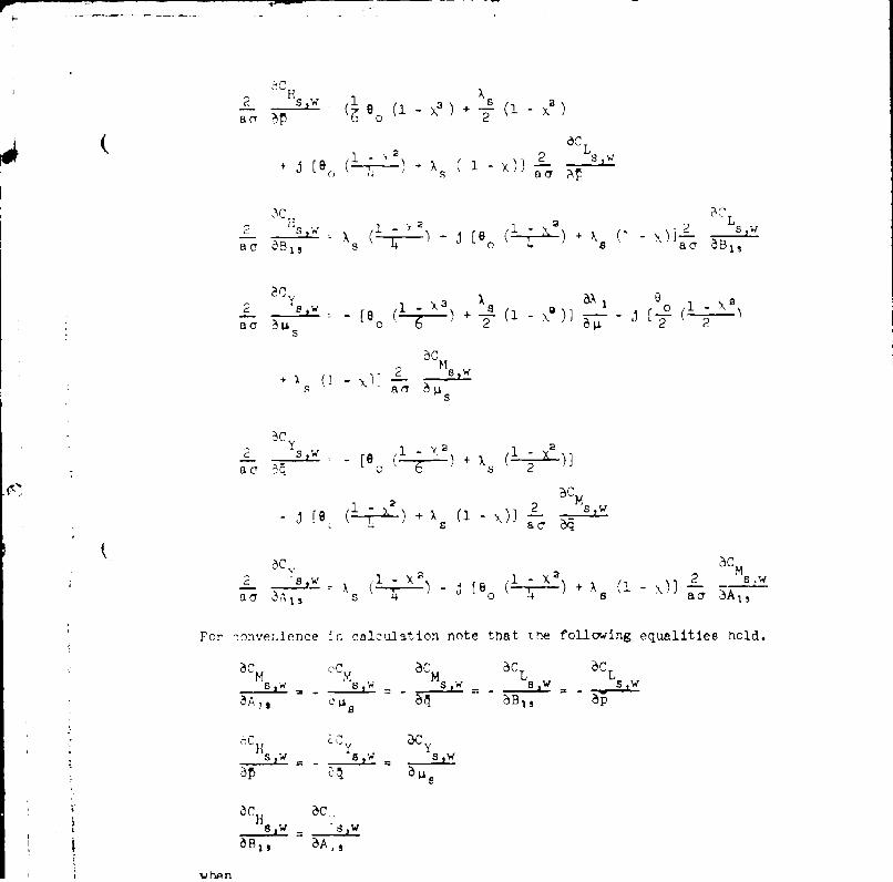
Th rslt o n 411lcJ n eApeRmES aIf dinvestintifom CatrlidO(c) 1 EUIYCASof thes hovering dAaiso nAR CA Ehbheparten l oft v hie Nare d4c6e n oprd nayla ersnttot ftehvrn eoyaic n

equtinsof otonarede~oedandd~used.Th epeinintl rogam icluin figt tstofa 010isalNaalArouDevmoelopen sdiCuentPioed and P nioe nlgcoptrsmltos ftehvin dnmc onpAir led w Teh nologyt tet eults , Th ntl~c ffebc tb zto I tvstte arIdC A11ePC AINnWGimG~dtosmd

formrvastaiwzto sytA 18 o7 SCrv h oein prto ya eil io iHEDLtEdmto cus

16DISRBTO STATEMEN 14).0 Ih dO' *NV5 5o£QLSIUCASFE

-~~~~~~~Apoe for Public CRUelease. HI ~O (~n M~ 3

SECPIJPTY CLASSIFICATION OF TWO&9 PAOUI(W%.e Data BJittt.d)

11tUfflyy C6AJ640ICArWIo OPP Twit PA6U4Wb" Do.leI.4
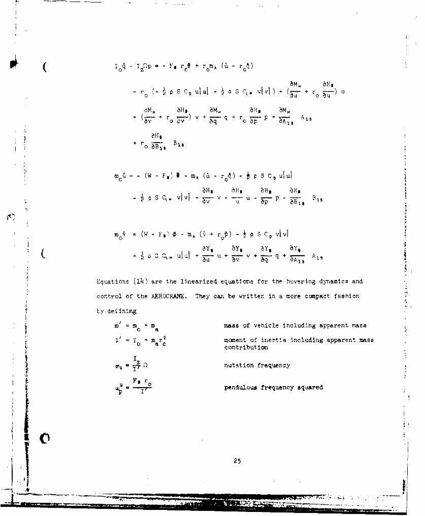
INTRODUCTION

In mid-1974 All American Engineering Company (AAE) funded, built

and flew at the Company's Wilmington Delaware plant a 0. 1 Froude Scaled

free flight spherical model of a 50 ton slingload A EROCRANE, In October

1974 AA E proposed to the U.S. Navy a program to perform the engineering

and fabrication to modify the model to provide proportional remote control;

install instrumentation and provide a monitoring station; conduct flight tests

in a government airship hacger; and reduce flight data. This was responsive

to the U.S. Navy/U. S. Forest Service interest in the AEROCRANE concept

and its potential application to a variety of civil and military short haul

heavy lift applications.

In June 1975 the Navy issued contract N00019..75-C-0418 to perform

the work proposed, including the planning and execution of a flight test pro-

gram at the Naval Air Station, Lakehurst, New Jersey, to determine:

a. Trim conditions for a range of speeds, gross weights and

vertical center of gravity positions.:4-

b. Rigid airframe dynamics in response to discrete control

input excitations.

c. Regions of deteriorated flying qualities in forward flight

and vertical descent.

The Navy selected the Naval Air Development Center (NADC),

Warminister, Pennsylvania to provide technical direction of the contract

effort. AAE selected Princeton University (Department of Aerospace and

Mechanical Sciences), Princeton, New Jersey as its subcontractor for model

instrumentation, flight test, and data collection and analysis.

By October 1975 it was apparent that weight and cost growth in the

model, mostly associated with the instrumentation package, would necessi-

tate the construction of a new, larger 0. 1 Froude scaled model. This led to

schedule slippage and cost growths which were accommodated in a contract

amendment in March 1976 providing for the construction and flight test of a

new model.

!;;7-

Hovering flight tests commenced in Hanger No. 1 at the Naval Air Station,

Lakehurst on 13 April 1976. These continued until 22 April 1976 at which time the

test model received minor damage during an in-flight -ontact with an extended

boom of the ground support vehicle. The primary cau- of the 'accident" was the

development of a mild instability in hovering flight, The ground based controller

had difficulty in detecting this instability, in its incipient stages, from his obser-

vation point on the ground. This contributed to, and was aggravated by, failure of

the heading - hold retrograde system of the model and resulted in loss of control.

This report discusses, inter alia, this instability and the relatively simple,

straightforward corrective measures recommended for adoption in future flight

test vehicles. Moreover, it reports the successful development of a verified

analytical model which can be used in forecasting future test results.

Following damage to the test model, NADC, NAVAIR and t he Contractor

mutually agreed: that the objeclives of the hovering phase of the flight test pro-

gram had been achieved, that the data collected during that phase should be

reduced and analyzed, that the hovering phase results were to be reported,

and the effort under contract N00019-75-C-0418 be limited to hovering flight

tests. This was effectuated in a contract amendment dated 6 August 1976.

The report which follows constitutes a summation of all effort under

the aforementioned contract.

lllO"rill

.I W W O N - -3

L X

AI ANALYTICAL AND EXPERIMENTAL INVESTI•ATION

OF THE HOVERING DYNAMICS OF THE

AEROCRANE HYBRID MEAVY LIFT VEHICLE

by

W. F. Putman andH. C. Curtiss, Jr.

lecmncal Report 1291

Princeton UniversityDepartment of Aerospace anc, Mechanical -cienceb

4

:v.

DDC C

D .t

June 1976

D-WIUUT16N jTIkTI Nt AApgmvd fag pk41 r~o1iaW

5 D~stdbuE~Unliutdw

Sg~ T M.9AP Y

A r.lJ '-yoyp? scaled dynamically similar free flicht model of a

S I , C) I *. .:.•RCAANI. v.i Acl n - las igied , fahricated and'

testei in hove'ring, 'light by the staff of the .yn•amic Nod1-l -rack,

.orospnce and Mechanical Sciences Pepartment, Princeton University, III

allition to the model, instrumentation and grounA support equIpment

rneceqnarv to operate the model were designed and fabricated. The ex-

p•.:-ne.'.,ta1 program .as conducted in hangar No. 1 at Lakehurst Naval

Air 7totion, Iakehurst, New Jersey.

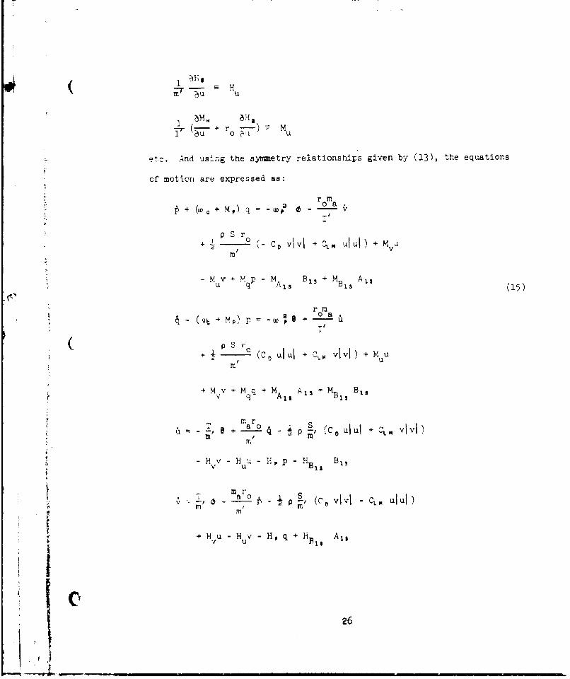
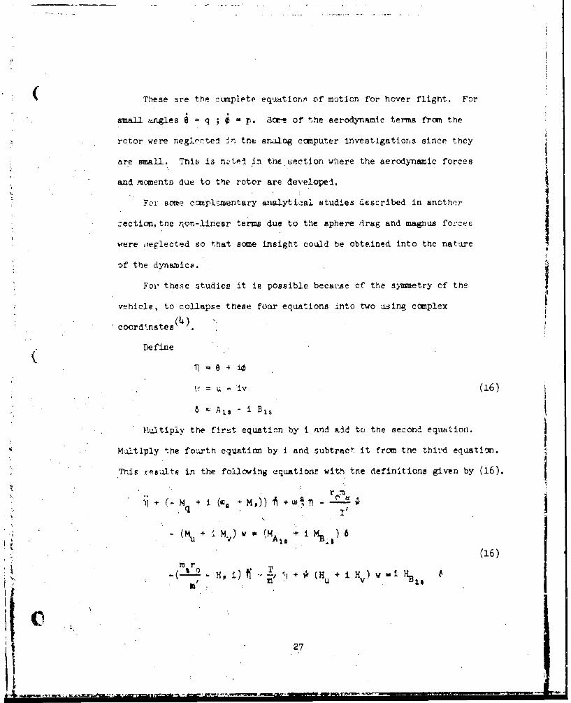
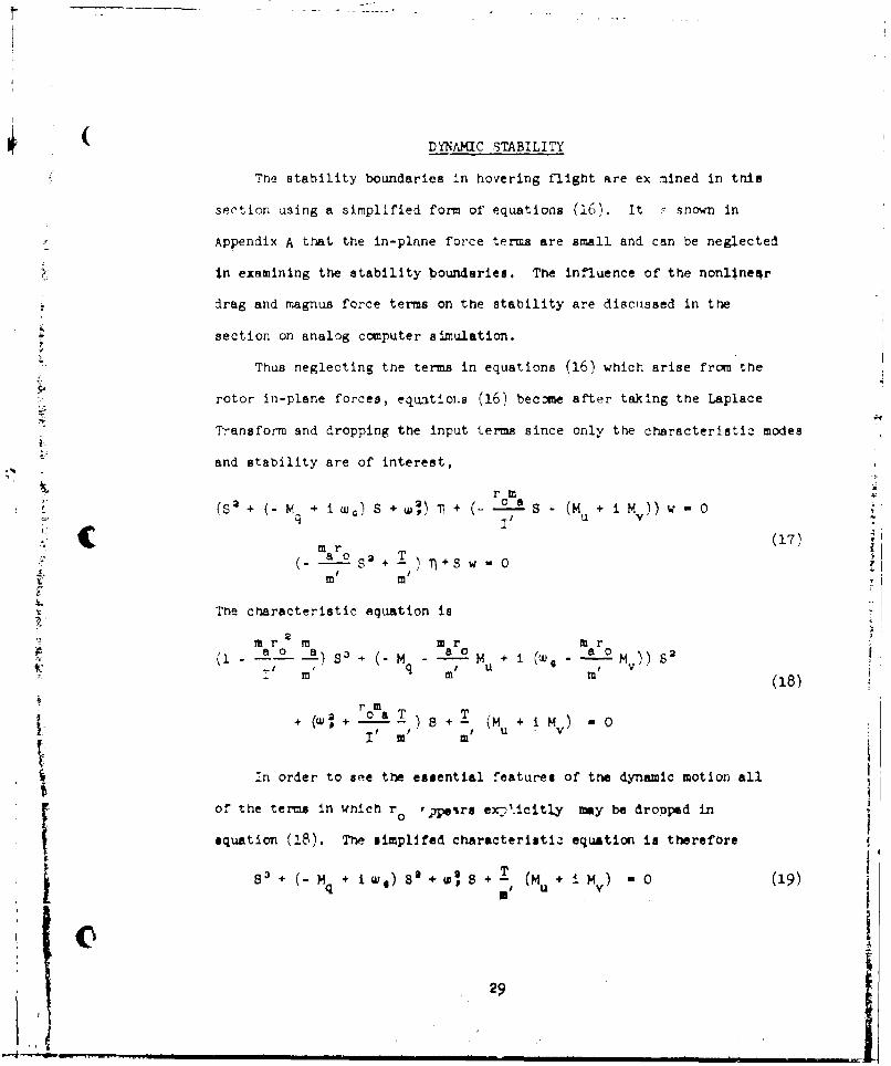
Ti. analytical representation tf the hovering flight dynamics was

develcped including theoretical techniaues for prediction of the vehicle

aerodynamic stability derivatives. These analytical representations

-w..reI erpluc'ed in a, ar, alog com_;tcr si=uaticn of t~ne <vcnicle d".

to investigate the dynamic motions of the model in hovering flight.

Excellent corrrelation of the analog simulation with the experimez-tally

obserT-ed vehIcle dynamics was obtained. In addition, a simplified analytical

representation of .!:e vehicle d1ynamics was developed which provided good

physical insight into the dynamic motions and aided greatly the understanding

and interpretation ,f the dynamic 'renavior in hovering flight.

Studies were made analytically and with the analog simulator of the

influence of feedba-k etabilization on the vehicle's hovering dynamics,

with and without piloting. It was determined that a feedback stabilization

utilizing crossed attitude feedback was both practical and effective in

stabilizing the motions and allowing the remote operator to position the

model satisfactorily in hovering flight.

I

1/

TABI fl: , ;N'mi;riS

:• ,i 'i -L 'YS PI~ b] HS ....................... .......... ................

;; !A ' r .................................................. .......•7 ..... . ..- , . .. e. .. .. .... .. ... .ee .e e, . 4,. e . . e .. . .. . .- , . . . .. .- . . . -.. . . . . . . . -. •

E:XPvPT!,h, TAL APPAPA P ................................................ 14TABLE: M: DEL 7E2K,,TRIC AND IW[rRTIAL CEARAOTRERISTYCS ................ 5FxfF)rE .ENTAL PROC•RAM .............................................. 15FQýUATI•,NS OF MOTION ................................................... 20PUAYT•7 STABILITY. ....................................................... 29FYYD1W •K EFFE-C G> ............................ I........... .............. 36;A ..L ,T Z -JIATT 0 ; .............. .......... ............................ 1O

.' .' ." .. ....... I......C . .. .I.'!'" S .. ............ .... .................. .....................

P... S........................................................

r,7. . .. . . .. .. . .. .• ., . . . . .e , l .~., , . .. . .. . . .... . .. . . . . . ... .,.,. . ..,. .. .,.-. .- . .

APPE7'NDIX A: ROTOR AZR- D'DDYAVICS ....................................... [77A?,,,mTX B: ThE3ITBICAI VAL'ES FOR S-A-LITY'' DE.I.AI S. ............. 91

a-

LTI, OF ILI; 27BATIU0

F~ gi, 1

I ~ :a .• .' ') •- a Jr v o ...................... ........ 14 9

dI 'fn•mi , *Ael in Hoverlig F] igtt ........................... 50

o ;oneral -anzement Drawln oe ...........

14 Internal A asembly Struoture .............. ........

P Potat ing -'ngs of .,odel .................................... 53

- otating ',.ng Foot Assembly................................

v Rocting .ing Tip Assembly and Nacelle .....................

cZror.:!siq n %,stem Assembl .................................. .

FRtatl.a g : ing Fitcn Act us)tr s Tntl. . )7

iC ;oniola Assemb! .............................................

T U -q, 1 r a! S o rt Boom .....................................

12 Pilot's Control Console ...................................... O

13 lngineer's Control Console ................................. 1

1 1Anclp - -tack a--' .ýS ceslip Vanes ......................... 62

15 Axis System and Nomenclature .................................. 63

16 ,ngular Dynamic Modes of Motion of AFPC(DA,7 ............... 64

17 Stability Bounrlarier as n Function of PendulousMode Freqoenoy ................................................. 65

1? Pbhysicl Yicture of Retrograde Mcde Notion ..................

I) 19 Fhysical -icture of Advancing Mode Motion .................. 67

2C, Typical .- Ansient Response of AEROCRAIE in HoveringFlignt to Longitudinal Control Step Input .................. 68

21 Stability Boundaries in Dimensionless Form IncludingDependence of Model Craracteriatics on Thrust Coefficient.. 69

I gure P ag-e

22 Dimensionless Statility Boundaries, Thrust Coefficientvs. Dimensionless Pendulous Frequency Squared ............... 70

23 Toot Locus, Lual Axis Attitude Feedback ..................... '711

24 i~oot Locus, Dual Axis Rate Feedback ......................... . 72

25 Analog Sslematic............................................... 73

26 Time History - Nominal Configuration ........................ 74

27 Time History - Nominal Configuration Limit Cycle as

Compared to Flight Test Data ................................. 75 7

26 Time History - Crossed Attitude Feedback, KA = 0.i1% ....... 76

A-1 Definition of Rotor Forces and Moments ...................... 8

A-2 Comparison of Theory and Experiment for ControlEff-ctiveness of Rigid Pr'opeller ............................ 89

Variation of Cosine Component of induced Velocity withForward STe)ed and Ahle of Attack as Determined by

Theory of Reference 7 .................................... 90

"1"

-• ----- 1- -~-

Nc1VFNCLAUJ~RE

a rotor blade lift curve slope

longitudinal cyclic pitch

b number, of blades

lateral cyclic pitch

c blad, chord, ft

drag coefficient of centerbody, D D •

0 V rrR 2

LCL rolling moment coefficient, CL =

pn (OR) 2 R

C L magnus force coefficient of centerbody,

Cl V2 TnR2

C pitcning moment coefficient, CM = P-R' (OR)' R

C_ thrust coefficient, C- Ti pnR2 (m)(,2

Fe buoyant force, lbs

1I8 rotor Tnplane force, body axis system, positive to the

rear, lb

liu, M stability derivatives divided by m' and I' respectively

I' moment of inertia of vehicle including apparent mass

contribution

I vehicle moment of inertia about X and Y axes, slug ft 2

,:-- 0

T.:•, I vehicle moment of inertia about Z axis, slug ft 2

Sz

b proportionality constant between harmonic inflo and

rotor aerodynamic moment

N iii

p

..U ,•-- ,. , :

K A attitude feedback gain, in general a complex number,

tad/rrv/ or deg/drjg

-rate f~edback gain, in general a complex number,

rad/ra.A/s So

Le rolling moment, body axes, positive right side dwnm, ft-lb

L,. rotor humb moment in roll, body axes, ft-lb

;M sum of mass of vehicle and apparent mass, slugs

mA apparent mass of vehicle, calculated for centerbod~v only, slugs

m vehicle mass, slugs0

pitching moment, body axes, positive nose up, ft-lb

H• rotor numb moment in pitch, body axes, ft-lb

p vehicle roll rate, pusitive right side down, rad/sec

q vehicle pitch rate, positive nose up, rad/sec

a. p dimensionless pitch and roll rate, q p. =• •

ro distance between center of buoyancy and center of gravity,

positive for center of gravity below center of buoyancy, ft

F radius of rotor, ft

F, radius of centerbody, ft.

S frontal area of centerbody, ft 2 , Laplace operator

t time

T, rotor thrust, along shaft, positive up, lbs

u longitudinal velocity, positive for forward motion, ft/sec

u, v dimensionless translational velocities, u =lRR' v - ýR

v lateral velocity, positive moving to right, ft/sec

V volume of centerbody, ft3

iv

:4 ~-'- . '•-: -. L,

w complex translational velocity, w u - i v, fps

W weight of vehicle, lbs

X8 longitudinal force, body axes, positive forward, lb

SY lateral force, body axes, positive to right, lb

Sz complex translational displacement of center of gravity

of vehicle, z = x - i y

*.SE blade element angle of attack

" complex control input, A - B 1 5 , rad; blade profile

drag coefficient

n, complex angular displacement, e = 8 + i 0, rad

e blade pitch angle with respect to shaft axis system

e6 6 - A 1 , cos 13 B, sin

9 vehicle pitch angle, positive nose up, rad

e rotor collective pitch, rad

X] ,rotor inflow ratio, positive for flow up through rotor

S),M cosine component of dimensionless induced velocity due to

blow back, IQ = I x

I IL harmonic inflow components due to rotor aerodynamic

j 2 CM 2CLpitching and rolling mments, XI . J - L X " J.

rate of change of cosine component dimensionless of induced

velocity with radius due to "blow back"

rotor advance ratio

vconstant part of induced velocity non-dimensionalized by OR

v

1 'i• ll i li m l ll ~ ll,,el • llJ''• mlllm

P density of air, slugs/ft 3

be

0 rotor solidity o b R

rotor ',lade inflow angle

0 vehicle roll angle, positive right side don, rad

blade azimuth angle, measured from don, wind, positive

in direction of rotationI

U G nutation frequency, WQ = 0, rad/se'i,

F r2 2 aB d

0- square of pendulous frequency, w = -, rad 2 /seI,

0 rotor./centerbody angular velocity, RPM or rad/sec

natural frequency of vehicle motionRB

fractional radius to root of blade N =

arg P argumert of complex distance from pole to characteristic root

arg Z argument of complex distance from zero to characteristic root

( W •rotor forces and moments in a shaft/wind system. H} is

parall-i to the relative wind vector and positve inadirectiori

opposite to the vehicle motion. Y is perpendicular to thie re %tivr

wind vector and positive to the right. YsW rep-'esented as a

vector is positive to the right and L is positive ill the

direct on of motion,

() 4eifferentiation with respect tc time

etc rotor %erodynamic stability derivatives

vii

IN T'RODUC TI ON

This report presents the results of an experimental and theoretical

investigation of th, hovering dynamics of the AEAOCRANE hybrid heavy 1ift

v.? hicl .

There has been 2onsiderable interest in recent years in developing

a very havy lift vehicle capable of hovering and slow translational

flight such that, it would be capable of moving payloads of the order of

'0 tons, that is, well in excess of' the capability of existing helicopters.

if sueh a vehicle culd be developed it would find many applications in

both the military and commercial spheres, ranging from offloading ships

to logging. COne particularly attractive concept for achieving this

objective is the AEROCFANE, a unique concept proposed by the All American

ngineer!ng -ompany. 'It consists of a spherical centerbody filled with

lifting ,as. Four rotating wings are mounted on the equator of the sphere

ond the entire assembly is rotated by propulsion systems mounted near the

tips of the weings. Below thQ sphere, is mounted a gondola or pilots

.. ration wnich is y'a,: stabilized and does not rotate with the rest of the

vehicle. The vehicle is configured such that the lifting gas provides

a buoyant force equal to empty weight of tne vehiele p1-ip one .plf of

the weight of the maximum payload. Vertical equilibrium is achieved

through the thrust ,f the rotating wings obtained by means of a collective

pitch control. Translation is obtained by cyclic pitch.

The success of this vehicle will depend to a large extent on the

ability to hover and maneuver precisely at low speeds. This report

describes an experimental and theoretical investigation to determine the

hovering dynamic characteristics of such a vehicle using a Froude Scaled

E ynamlc Model of a proposed 50 toa payload vmhiclc.

0.10i7 Fro'ode 3caled dynamic model c. a proposed full scale AF.PnRR,NF

vehicle was desigrnýi and constructed by: irincetoer University. F!overiri.

flight experiments were conducted to evaluate the control and dynamic

response charact-ri!tics and a theoretical model. was developed for com-

parison with the experimental results. The research program as origirially

rlanned included forward flight experiments as well. However, as described

in this report owing to the nature of the dynamic characteristics of the

vehicle in hovering, a more extensive hovering investigation was required.

In addition, owing to the presence of a mild hovering instability in

hovering flight a more extensive theoretical investigation was considered

to be desirable in order to fully understand the hovering dynamics before

proceeding to undertake forward flight e:xperiments. In additioxi, it is

considered highly desirable, as a result of the hovering flight ccperiments,

to develop a theoretical model or the forward flight dynamics and to

examine the estimatel vehicle characteristics on an analog coMpUter prior

to proceeding with forward flight.

For a number of reasons a series of experiments with a Froude Sealed

;1:nam4td model was -elected as the most efficient and cost effective means

iet-!rmining the contrul ckmracteiistics of an PROCFRANE tyW vehicle

rather than conducting a more convcenticnal wind tunnel test. The primary

reason for rielecting an experimental irvestigation using a fully instru-

mented dynamic model was the unique configuration of the proposed vehicle.

It appeared highly probable that a wind tunnel investigation baned on

conventional practice might not include measurement of the significant

aerodynamic characteristics which determine the hovering dyn~ics. A

2

@ I

socond rpason of equal importance is the fact that sin.e the proposed

vehicle is designed for lifting, moving, and positioning p-ecisely

heavy payloads determination of the control and btability characteristics

in hovering flight lire of primary importance to the success of the vehicle.

These characteristics are directly measured using a free flight model

rather than being indirectly inferred from wind tunnel experiments.

Further, since hovering flight is of major importance for this concept,

very low speed experiments are required. Difficulties are e.icountered

in obtaining experimental results in a wind tunnel at very low speeds

owing to problems associated with maintaining a smooth uniform flaw

field without recirculation effects. It can be seen later in the

report that one of the primary quantities determining the character of

"the hovering dynamics is the rate of change of pitching mment with

translational vclocity for velocities near hover, a quantity that would

be difficult to measure in a wind tunnel but can be directly evaluated

from a free flight model. The last fac'or of importance was the interest

in achieving as large a Reynolds Number as possible on the centerbody.

It was considered that a Froud<ý Scaled free flight model with an overall

-diameter of' approximately 30 feet would meet the Reynolds Number ob-

4 jective in a more cost effective manner than a wind tunnel model with

comparable Reynolds NLmber.

This report prisenta a description of the model and the flight test

program which was conducted. Experimental data obtained from the flight

test program are presented along with a theoretical approach to predicting

the dynamic stability characteristics in hovering flight.

T M3

EXPERTMFNTAL APPARATUS

1-1,ode I

7he model employed for the experiments described in this report is a

0.10",7 Froudo Scale model of a proposed 50 tcn payload AERRONRF vehicle.

Photographs of the model are shown in Figures 1 and 2 and a general arrange-

Trent drawing indicaling principal dimensions is shown in Figure 3. Table I

presents a list of the important model inertial and aerodynamic character-

istics.

Although it had been the original intent of the program to modify an

existing uninstrumented 0.1 scale AEROCRANE model for use in the experimental

investigation, detaýled design studies indicated that this would not be

desirable. The additional weight of the instrumentation package required

for model control a:.d data acquisition, even with a larger diameter gas

envelcpe, would result in an average blade lift coefficient approximately

I0•, higher than the proposed full scale value. Thus a completely new

model was required in order to maintain proper aerodynamic scaling.

It should also be noted that while a proposed full scale venicle

would have considerable excess buoyancy with no payload, it is not

possible to achieve this condition on a small scale model owing to the

Jncreased specific weight of many of the components such as the power

plants in addition lo the fact that an instrumentation package was installed.

Model ;t ructure

Ž7 The internal structure of the model spherical centerbody consists of

four mutually perpendicular radial members in the equatorial plane and a j

Sl Ii m •iI• • I r -"• •I[ i

, , '-i "-" K j

TA! ALE I

MODEL ,ThIAEPRIC AND IINI(PTIAL CHARACTERISTICS

Nominal Configuration

ROTr07 DIAMETER 37.3 ft

SPITERE DIAMETER 16.o ft

GROSS WEIRHT 191.7 lb

CENTER OF GRAVIT: 3.82 ft below equator

'pitcn & roll about cg 337.4 slug-ft 2

Ipolar 481.5 slug-ft 2

T11PUST 54 lb

BUOYANT LIFT 137.2 lb

VIR7JAL YASS 2.65 slugs

ViR'IAL INERTIA 38.7 slugs-ftI

UL9ILICAL WE-IGHT o.61 lb/ft

NOCTE: All values listed are for nominal operating altitude and

include sling load and umbilical contributions.

I

i.

south pole member. These members, fabricated of 3" O.D. thin-wall aluminum

tubing, are Joined together at the center of the sphere by means of an aluminum

weldment into which thce radials and south pole are inserted and secured. The

center joints are gas-tight thus allowing the instrumentation, control and

power cabling to pass up through the south pole and out the radials to which

the •-ings are attached. Gas-tight pass-througha are provided in the gas-

containing envelope to allow the radials and south pole to protrude through.

A photograph of the internal structure assembly is shown in Figure 4.*

The envelope itself, fabricated by ILZ Corporation, is manufactured of

Mylar impregnated Dacron sail cloth and in addition to the structure pass-

throughs, the envelope is provided with a gas-tight accest zipper, filling

nozzle, and pressure measurement port. Eight load patches on the surface

of the envelope are provided for attachment of the 1/16 in steel cable

( wing supports.

Wing Assemblies

The rotating wings or blades shown in a photograph in Figure 5, are

constructed of balsa wood covered with a thin film of adhesive-backed

plastic (Trade name "Mono-cote") with plywood and aluminum reinforceraent

at the load points. The root ends are provided with moahined fittings

for attachment of the wing-pitch servo actuators and the bell joint used

to attach the wingq to the tips of the radial tubes of the internal structure.

A photograph showing the detail of this assembly, including the radial tube

tip fittings, is shown in Figure 6.

The wing-support-cable tie-in fixtures are permanently assembled in

C'!]

Sthe wings as shown in the photograph in Figure 7. These fixtures are

welded of aluminum tubing and are attached to the wing structure by

means of a ball joint. Thus, the wing is simply supported with ball I

joints at either support; the lead-lag and flapping constraints are

"provided by t~e support cubles and feathering constraint by the servo-

actuators.

The propulsion system nacelle, including motor air cooling ducts,

is constructed of plywood as an integral part of the wing structure and

can be seen in the photograph. in Figure 7.

Propulsion System Assembly

Siwre are four propulsion system assemblies. Each consists of two

permanent-magnet d.c. motors coupled to a propeller shaft through a 2.67:1

reduction provided by toothed timing belts and plastic sprockets. The 30

C x 15 propeller is driven at a nominal speed of 2600 RPM. A brief wind

tunnel test was conducted on a propulsion system assembly. The experi-

mental results indicated a nominal operating condition of approximately

0.6 thrust horsepower and a propulaive efficiency of 75'ý. The motor-

belt-box system will produce I horsepower continuously and can be run

intermittently at 1.5 horsepower. A photograph of propulsion system

assembly is shown in Figure 8.

Wing Pitch Actuators

A detail photograph of a wing pitch actuator assembly is shown in

Figure 9. These units consist of a permanent magnet d.c. motor driving

a ball-screw actuator through a spur gear pua. A 10-turn cmductive

7

( plastic follow-up potentiometer is provided to measure the actuator

position (which corresponds to wing pitch angle) for the positioning

loop closure and data recording purposes. It should be noted that the

wing feathering actuation is done in the rotating system and hence no

mechanical swashplate is required. Instead, first harmonic feathering

"(cyclic pitch) commands are electrically provided by means of a sine-

cosine potentiometer mounted in the non-rotating system. The required

computational electronics are provided in the ground-based controller

system to allow first harmonic cyclic and collective comands.

The closed-loop positioning system consisting of the actuator

assemblies driving the wing has a one half maximum amplitude bandwidth

of approximately 5 Hz. The physical characteristic of this system is

such that its response is acceleration limited. At the normal operating

Cfrequency of .5 Hz (30 RPM) it can be considered to have a transfer

function equal to unity.

Gondola System

The non-rotating gondola is supported at the lower end of the south

pole by a pair of large bore ball bearings which transmit the payload

loads into the rotating structure. The gondola, attached to the bouth

pole, can be seen in Figure 2, and a detail photograph of the gondola

assembly is shown in Figure 10.

The gondola is positioned in azimuth by means of retrograde drive

motor driving through a spur gear pass visible in Figure 10. The azimuthi •yositioning control is accomplisbed by a closed loop positioning ser~ro-

mechanism driving the retrograde motor and utilizing integrated yaw - rate

poiinn oto sscpihdbyacoe opputoigsro

I0

gyro signals to maintain the heading hold. A back-up rate command loop is

also provided which utilizes the yaw rate gyro signal directly. Damping

and RPM sensing are provided by a d.c. tachometer.

instrumentation and control signals and propulsive system prer are

carried from the non-rotating gondola to the rotating system by means of

two slip ring systems, a Michigan Scientific instrumentation-quality 20-

ring unit and a National Carbon high-current 8-ring unit, respectively.

The gondola carries the balance of the airborne instrumentation and

control systems including the 3-axis gyro package and its electronic

package, the air data boom and its electronics, propulsion power recti-

fication and motor rerersing equipment, first harmonic feathering sine-

cosine potentiometer and the ballast support package. The balance of the

instrumentation, control and power systems are mounted in the ground-based

control system and connected to the model by a multiple conductor umbilical .

cable.

Ground Base

The ground based controller, which is mounted on a flat bed truck,

* provides all the necessary power, signal conditioning and controls to

operate the model and record the data signals. It consists of tle

following sub-systems:

1.) a gasoline engine-driven 5 KVA, 120 v, 60 Hz, single phase,

a.c. generator;

2.) a gasoline-driven 10 KVA, 200 v, 400 Hz, 3 0 alternator with

a solid-state controller;13.) power amplifier systems for the closed loop model control

actuators;

9

______________________i

S4.) pilot's control console;

5.) flight engineer's console;

6.) data acquisition, signal conditioning and computational

electronics and data recording equipment.

The entire controller, excluding the 60 H& generator, is mounte4 oi

an 8' x 10' wooden pallet along with seating provisions for the pilot,

flight engineer and test engineer; the pallet is in turn secured to the

truck bed. Also mounted an the truck bed is a boom 47 ft. long fabri-

cated of welded aluminum pipe and guyed to the truck with steel cables.

The booa, shown in Figure 11,serves to support the ground based end of

the umbilical cable in a position that will permit the lowest point of

the umbilical catenary to clear ground obstructions and allow the model

to be flown in a position relative to the truck where the pilot can

C observe both pitch and roll motions.

60 Hz Generator

The 5 KVA, 60 Hz generator is a commercial gasoline engine driven

unit that provides all necessary power for the ground base with the

exception of model main propulsion power.

400 Hz Alternator

The 10 KVA, 3 0, 400 Hz gasoline engine driven alternator system

was designed and assembled specifically to provide model propulsion power.

It consists of a govermwnt surplus 2OO Hz, 3 b alternator belt driven

by a 30 P Wisconsin gasoline engine with a clutch coupling. Alternator

voltage output is controlled by a separately-excited solid-state field

10

IlO

control power supply. The power supply has provisions for automatic

£ control of model RPM by use of the d.c. tachometer signal on the model

gondola. Celection of manual or automatic control is provided at the

flight engineer's console and a back-up self-excited field control

provision allows model RPM control by the test engineer in tie event

of a power supply failure, The a.o, output is transmitted through the

umbilica3l to the •odel where tt is rectified to d.c,

Oervo Power Aýplifiers

The five d.c. power amplifiers used to provide loop closures and

power amplification for the four wIng pitch actuators and the retrograde

drive motor are rack mounted in a cabinet at the flight engineer's position.

The amplifiers are capable of operation at a continuous output of 100 watts

with a bandwidth of d.c. to 10 KHz and contain signal summing, equalization

( and error detection circuits.

Pilot's Control Console

A photograph of the pilot's control console is shown in Figure 12. The

console contains the centrally-mounted control stick with longitudinal and

lateral cyclic commands and a top-mounted twist knob for heading ccmmand

(or azimuth rate command in the back-up mode). Collective commands as well

as longitudinal and lateral cyclic trim commands are provided by means of

thumb-wheels arranged around the control stick. Three ten-turn digital

dial potentiometer8 aie provided for adjustment of cyclic stick and thumb-

wheel collective command authorities. A galvanometric voltmeter displays

flight path angle generated from angle of attack and pitch angle signals.

to

JU

( Flight Engineer's Console

The flight engineer's console, shown in a photograph in Figure 13,

contains monitoring and control provisions for most of the model-controller

system fuictions. Tlicluded are galvanometric meters for displaying pro-

pulsion systems current and voltage, model RPM, automatic RPM control

loop error, truck velocity and the three-axis rate gyro outputs. Digital

voltmeters are provided to display selectively control comtands, model

angular rates or model attitudes and heading.

Signal Conditioning, Computation and Recording

All of the signal conditioning and control computational electronics

are rack mounted in the cabinet housing the servo power amplifiers. Data

signals to be recorded are carried to the data cabinet by an interconnecting

cable.

The data recording system, consisting of signal patching boards,

oscillograph recorders and magnetic tape recorder was supplied by the

sub-contractor and was not developed as part of the model-controller system.

Instrumentation

The instrumentation system includes measurements of model controls,L

air data, three axis rate gyro information, model RPM and truck speed.

Model Controls

SThe model control positions are measured by means of the follow-up

potentiometers on the wing pitch servo actuators. Since these potenti-

ometers measure the actual blade feathering in the rotating system, they

are inconvenient for data reduction purposes and the model collective

and cyclic coands in the non-rotating system are also measured and

A ' •recorded.

12

(JAir Data

The air data instrumentation consists of vanes to measure angle of

attack and sideslip using low-friction potentiometers and a low airspeed

transducer. These instrents are moiunted on the end of a 6' boom

attached to the gondola as shawn in Figure 4

The aerodynamic vanes shown in Figure 14 have canard surfaces to

provide aerodynamic damping. The low airspeed transducer is manufactured

by J-Tek Corporation and measures airspeed by the correspondence between

the airspeed and the shed frequency of the vortex behind a right circular

cylinder perpendicular to the flow.

3-Axis Gyro Package

The model angular rates are measured by means of three mutually

orthoginal rate integrating gyros carried in the model gondola. These

gyros, obtained from government surplus, are of inertial platform quality

and have extremely low drift and hysteresis characteristics. It is

therefore possible to integrate their rate outputs to obtaii. accurate

attitude informati,..i. The integrations are performed in the ground-

baaed computation bod both rate and attitude signals are displayed and

re:ýcr-del,3V

.Tuk Velocity

The truck velocity measurements are obtained from a "fifth-wheel"

type transducer mounted on the rear of the truck. This syatem, which

& was rented for use in the subject experiments, provides a d.c. voltageKproportionAl to truck oeed and is recorded and displayed on the

13

-w j

( engineer's console.

Other data signals that are measured are model RPM, rotating system

azimuth relative to the gondola, model propulsion system voltage and

current and a 1 Hz time standard.

1• 1

9, I

4 KXFE RIMENTAL PR OCRA1M

The experimental test program was conducted in Hangar 1 1 at the

Lakehurst Naval Air Station, Lakehurst, New Jersey after a com~plete

model checkout in the aircraft hangar at the Forrestal Campus of

Princeton University.

The planned test program included measurements of the model trim

conditions and control input response time histories through the for-

Sward flight envelopeý of the model. Initial hovering flights indicated,

nowever, significant difficulties in controlling the lightly-damped

dynamic mode and all flight testing was confined to hovering flight

with a stationary ground base.

reliminariny loveririg Tests

Prior to the data acquisition flight experiments, hovering flight

Stests were performed to familiarize the pilot and test personnel with

the model behavior. These tests were conducted without the gyro

package and with the retrograde drive system disengaged; the gondola

was positioned in heading by means of light lines connected to a boom

attached to the gondola and tended by ground personnel. In this con-

dition, without the gyro package, ballast and power and instrumntation

cabling, the model was 3.5 lb buoyant; the umbilical providing power

and instrumentation signals, without gyro cables weighed 0.38 lb/ft.

]Aovering flights were performed with 12 lb and 25 lb sling loads

suspended frc the gondola on approximately 10 ft of line and thus

the model was approximately neutrally buoyant at the height at which

the sling load was engaged. In general, the model was well behaved,

15

",f - -4"I !"" .. --

although sluggish in translation due to the low thrust levels, at the

lower altitudes where the combination of sling load and supported

umbilicrl weight required thrust levels less than approximately 30 lb.

At higher altitudes where the supported unbilical weight wao greater,

particularly with the heavier sling load, the thrust levels were h~gh,5

enough that the retrograde precessional mode (discussed elsewhere in

this report) became unstable and produced serious difficulties in

controlling the model motions.

T' At the higher thrust levels, the model behavior was characterized

by a slow growth cC the retrograde mode that, with very careful con-

centration, the pilot could reduce in amplitude by means of discrete

pulse control inputs, Eventually the retrograde motion would increase

in amplitude again, however, it was difficult during the initial flights

" ( to detcrinine if this mode of motion was characteristically unstable or

a lightly damped mode forced by inputs from the heading control lines: or recirculation. There was also qualitative indication that the

severity of the model motions was influenced by initiation of descent.

Altrougn the preliminary hover flights were performed without the

"inst.umentation package, photograp),ic coverage was provided. Review

j of these movie films indicated that during some of these flights,

particularly after descent from altitude was initiated, the amplitude

of the model pitch wad roll motions grew to as much as * 250 and

combined measures of thrust reduction, pilot control inputs and

ground crew action were required to arrest the motions.

16

( The prelininary hover flights were accamplished without serious

incident due in a large part to the fact that a lower altitudes, with

mich of the umbilical weight not model-supported, the thrust was low

and the level flight dynamics were probably stable. Also, the umbilical

was not supported from the truck tower but went directly to the floor

where it was attended by ground crew. In subsequent flights, the

umbilical was mounted on the tower. This arrangement contributed to

an incident that damaged the model and terminated the test program.

Fully- Instrumented Hover

Following the preliminary hovering flights, the full instrumentation

package was installed, the retrograde heading-hold loop checked out and

the lines removed from the air data boon previously used for heading

control. It appeared that extraneous inputs from these lines were

* strong contrilutors to the observed model motions and their removal

* might well improve the hovering flying qualities.

Owing to the combination of higher ambient air temperature and

the addition of the gyro instrumentation package, the model without

umbilical, was 12 lhs heavy; the coplete umbilical weighed 0.63. lbs/ft.

One hovering flight, of approximately 30 minutes duration, was acceor-

plished with the Instrumented model carrying a 12 lb sling l•ad, and with

the ground end of the umbilical suspended fro the truck tower. The first

half of the flight was flown at fairly lo altitudes and corresponding

thrust levels of approximately 40 lbs. During this portion of the flight

the model and all systems were well behaved with the exception that the

yaw rate gyro integrator, used to maintain the hlaing-hold loop, showed

17

. .1

a drift of approximately 2 0 /sin. This drift had not been• encountered in

the laboratory check out of the system and was apparently caused by the

unfavorable environmental conditions at Lakehurst.

The latter half of the flight was flown at higher altitude to permit

more maneuvering flight experience. The thrust level for this portion of

flight was estimated to be approximtely 55 lb at which point the preoes-

sional motion began to develop, indicative of a characteristically unstable

mode. The recorded data indicate that the retrograde mode grew until

it reached an amplitude corresponding to approximately * 2 of pitch

and roll attitude excursion with a period of ll.4 seconds. The period

and magnitude of this motion was approximately constant for nearly 5

minutes, indicating a limit-cycle type of dynamic motion. During

this time, the integrator drfit had increased until almost two-thirds

( f the available offset command had been used to compensate and maintain

a constant gondola heading and the test engineer elected to terminate

the flight. Upon initiating the descent, the precessional motion began

to increase in amplitude and in six periods had tripled in amplitude

at constant frequency. At this time, oing to the large model motions

and resulting torqoe inputs due to sling load and umbilical mct!onn,

the heading-hold retrograde loop failed and the back-up rate mode was

activated. For approximately 45 seconds the model was operated in this

mode although complete control following the transient was never established

0and the model precession~al motion attained amplitudes as high~ as * 15 in

pitch and roll attitude. At approximately 20 ft of altitude the rate-control

III18i

Sretrograde loop failed, again due to excessive torque inputs, and the

model was out of control. Simaltaneously, the ground crew hauled the ]model down by means of the umbilical and the flight engineer began to

reduce the RPM. The model rotation had not been arrested by the time

the gondola vas in the hands of the gouid crew and the rotating model

struck the end of the imbilical suspended from the truck tower resulting

±iu damage to the model.

!-

C

0 J-9

-- -

OI

The linearized equations of motion describing the dynamic motions

-f the AEROCRANE near hovering flight are developed in this section.

A body axis is used with the origin at the vehicle's center of

gravity as shown in Figure 15. The X-axis points forward, the Y-axls

to the right and the Z-axis dornwsrd. Note that the angular velocity

o0 the centerbody and blades is in a clockwise direction when viewed

from the top, i.e., opposite to that of a conventional helicopter. A

four-degree-of-freedom model is employed since the linearization

assumption will decouple the vertical translation and yawing degrees-

of freedcma. Thus, the four equations of motion are

I 0 + I Oq - L,

c I4 -1IZOp - M(1

m = X1,

mo - Y e0

It is assumed that the center of gravity of the vehicle lies on

tne shaft. The external forces and moments, denoted in equation (1)

by L9, M9, XI, Ye arise fram the following sources.

a.) The- buoyancy 9 orpe as a res,Llt of the helium filled

centerbody.

F o.) The apparent mass effects(2, that is, the aerodynamic

forces acting on the centerbody as a result of

acceleration.

c.) The aerodynamic force and moants acting on the

rotating blades.

20

( d.) Centerbody drag and magnus forces.

e. ) (,ravity.

The conti Ibutions of eacn of these effects will now he developed. In

equilibrium hovering flight the equation expressing the sumation of

vertical forces is:

W - Fs- -o (2)

If the vehicle is perturbed through a small pitch angle 0, and m small

roll angle 0, the forces along the body axes arising from the gravity

and buoyancy forces are:

AX9- - (w - F,)e(3)~

tjY,= (w - F,)

The buoytint force will also produce restoring moments. Denoting r0 as

the dist,,nce the center of gravity of the vehicle is below the center of

buoyancy, the moments arising from the buoyant force are:

A L g= - F .r 0

Amen ~ FS r 0 0

The apparent mass effects arise fro the fact that a sphere accelerating

through a fluid, experiences a force proportional to acceleration(2). The

constant of proportionality fur a sphere in one-balf the volume times the

idcsity of the fluid through which it is moving, and the force acts at the

* centroid of the sphere (center of buoyancy) and acts opposite in direction

to the acceleration. Since the origin of the axis system is a distance

r° below the center of buoyLncy,m ents as well as forces are produced.

In addition, the acceleration of the center of buoyancy must be expressed

in terms of the center of gravity motion. The X and y components of the

21

acceleration of the center of buoy&ncY are:

a rXce 0

(5)

Yc0

Denoting the apparent mass of the sphere as

The forces due to the apparent mass effects are:

- m, ( r 4) (7)

-M4 ( + r P)

These forces act a distance r above the center of gravity and therefore

x give rise to te MCe•ntS,

r m, 'C + rf,So ~(8)

AM,= r zA (M r

The center body will experience a drag force and a magnus force as

Sa result of translation. Although these are non-linear terms they will

be retained in the analysis since the drag coefficient of the spherical

centerbody is large. The forces arising fro drag and magnus for'ces

are expressed as follows:

Axe-- ½p SC'ulul-j p s c. viv,

Ay. - p s C, v1vl+ i P S C. u•ul9

There is a lack of data as to the value of the mgnus force lift coefficient

(3)Cý, since the data available in the literature generally is conicerned

with the came in which the ratio of the peripheral velocity to the forward

velocity is small. Here, the interest is in the case where the inverse

22

of tnis ratio is small. Experimental data for spheres indicate a

limiting value of the lift coefficient as the ratio of the peripheral

velocity to forward velocity is increased(3) Therefore, for large

values of the ratio, CLM becomes independent of this ratio and is

consequently the form of the dependence assumed above. These terms

also produce moments due to the center of gravity, center of buoyancy

spacing.

The rotating blades give rise to hub moments and in-plane forces.

Analytical expressions for these terms are developed in Appendix A,

assuming that the blades are infinitely stiff in flapping. With the

exception of the rotor thrust, the equilibrium values of these forces

and moments are zero.

The followng linearized terms are present:

6YU + -+ + + A,$

[~6L AL, + r Aye

0 (41)

-r 0 Axe

where

aLm 6LM (3-2))

Owing to the symmetry of th vehicle in hovering it may be noted that the

4L following relationships exist amonig the variUm aerodynamic derivatives

• "3

( arising from the rotor.

am, 6LM apq 6Y5

7u Lv aNu av

am, bL, Hae aYe

F- -p Is -P.am, 3LM amg aye

As a consequencq in the following, for simplicity we replace the rolling

moment derivatives with the pitching moment derivatives and the side

force derivatives with the longitudinal force derivatives. The complete

equations of motion are obtained by adding the contributions given by

equations (3), (4), (7), (8), (9), (10) and (12) to equation (1), to

yield

IP + IQq - Fgr 0 rm (-+ r!) +

+ r 0 (-~ p S C0 vI v1 + iP a C~ M ul U, + (T- + r 7- Uo~u (14~)

""Y$ aYs 8L,+ (-+ r -- ) v+- p + ÷ BI

aye+ r 0 A,&0IAI

214

1 0 - -p - Fg re + r m, r~:

- r (- p S uC ulu - P S C, vi vI ~ +r -

6MH )H I ýMH 04i•M+ (7- -+ ro y-) v+ q + o-p ; ÷.-. A13ov ~q+ o ýpp + A1

+ r Bit

M) a - (w -F,) -M4 ( - - P S C0 u 1u

CI vHi vHi v uB4

u pm 4 (W- Fs) 0 - A (r+ r)- p S CO vIAI0

(+pS. ul II + - u + -v +y + -A 1,A

Equations (14) are the linearized equations for the hovering dynamics and

control of the AEROCRANE. They can be written in a more compact fashion

by defining

,m = + m mass of vehicle including aprarent massao a

I= I -+ m r2 moment of inertia including apparent mass0o a o0contribution

IO-z nutation frequency

0 r pendulous frequency squared

ii ~25

m-7 -ýu IIu

U

U- (•-+ ro •-)> Mu

etc. And using the syimmetry relationships given by (13), the equations

of motion are expressed as:

r m+ (w + MF) q= -4 0 _ oa

iI

pSr÷- - vc v C.~ uluL +M

!V

-.M +Mqp - MA1 , MBs A 1 , (15)

r mO4- (u++MP)p-w e + - a

+ (C~ DU1 u + CLM AivA +mU

+ Mv + Mqq + MA A 1 s +HB B1,

-T mr s cu4÷ .Il

-,e + a- • S- , (C III viVI)m fm

H v v HuU "I Ii p HB Big

m r S (c vivi - cM ), -, -a -2 I.½I

1 /e !f

+H.u H u v Hp q + isA

I26

1~26

These are the cumplete equhtiorn of motion for hover flight. For

emal j.ngles 0 = q ; p =. Scre. of the aerodynamic terms from the

rotor were neglected Jn tht analog computer investigations since they

are small. This is n.,te-l in the uection wliere the aerodynamic forces

and .oments due to the rotor are developed.

Fo-r some complmentary analytical studies described in another

:ecticn, tne Ion-linear terms due to the sphere drag and magnus forcesj

were o•eglected so that some insight could be obteined into the nature

of the dynamics.

Fot' these studies it is possible becat'Ae of the symmetry of the

vehicle, to collapse these four equations into two ,wing complex

coordý.nates~l)

Define

11-4 io

u - iv (16)

6 t - i BE•

Kuitlpiy the first equation by i nnd a-Ad to the second equation.

Multiply the fourth equation by i and subtract it from the third equation.

This xesults in the fo2lc4inq equationr with tne definitions given by (16).

+ '-+ + i (Wa + M,)) + •w• -----

" (Mu )w. (MA1, + i MB 6

" ' (i6)m r

(O-HP i) + *(Hu +' i H v H BIG

27

S.. . .

( Equations (16) are quite convenient for analytical studies as they are

now of third order rather than sixth order. The fact that this reduction

in order can be made implies that the dynamic motions of the vehicle will

essentially be circular motions with the radius of the circle either in-

creasing or decreasing with time depending upon the stability. That is,

if there is a characteristic root of the system described by (16) which

is imaginary, then there will be a solution of the form

: I]1 = ce t

(4)SI can be interpreted as a vector rotating at an angular velocity 0.

and thus neutral stability will consist of a circular or whirling motion.

Note also that the characteristic equation of this dynamic system expressed

in terms of complex coordinates will have coefficients with complex

( coefficients so that the roots will not in general appear in complex

r-IArs. The sign of the imaginary part of the root will directly indicate

Swhether the circling or whirling mode is in the sam direction as the

rotor's angular velocity (a negative imaginary part), or is in the opposite

direction (a positive imaginary part). The modes are referred to as forward

mcdes if they are in the same direction as the rotation of the rotor

retrograde modes if they are in the opposite direction.

28

oilI

11 '20

SDYNAMIC STABILITY

The stability boundaries in hovering flight are ex mined in tnis

section using a simplified form of equations (16). It ' shown in

Appendix A that the in-plhne force terms are small and can be neglected

in examining the stability boun4aries. The influence of the nonl]neqr

drag and magnus force terms on the stability are discussed in the

section on analog computer simulation.

Thus neglecting the terms in equations (16) which arise frm the

rotor in-plane forces, equtations (16" become after taking the Laplace

"TTransform and dropping the input terms since only the characteristic modes

and stability are of interest,

Sr m(S2 +(M+ i wC) S + W2) 7 + 0--- S - (M + iM 0))w O

m r (17)(_ a + T ) S w -0

m m

The characteristic equation is

2m r m mr M r

q u' u vS0 m (18)

Srm(w +-)s - (Hu +i! M) - o

4In order to see the essential features of the dynamic motion all

of the terms in which r ,ppe~ra e i y be dropped in

ex'Acitly myb rpe -

equation (18). The simplifed characteristiz equation is thereforet (- M + W.) so + W, -8 + T (M + iH) - 0 (19)

q MU V

29

To obtain some insight into the dynamics of this vehicle first(Iconsider some simple cases. If the aerodynamic derivatives are set

to zero and tha center of gravity Is coincident with the center of

2buoyancy, so that 0 0, the characteristic equation is

S 2 (S 4 i V 4) - 0

There is one whirling mode given by

S-- iw

This corresponds to a forward whirling since it is negative and its

frequency is the order of the rotor RPM.

WB -I

since

I*1.43

I' ,

This frequency is classically referred to as the nutation frequency of a

top(5)

Still with no aerodynamics,but with the center of gravity below the

center of buoyancy such thatwa ic non zero, the characteristic equation

, is

s (sI + i w. B + W 0 (20)

The roots of this equation are

I• There are now two natural or whirling modes: a com aratively large negative

root; the nutation frequency, and a relatively mcll positive root corresponding

C130

( to retrograde whirl. This low frequency is classically referred

to as the precession frequency. It is usually thought of as a forward

whirling in the case of a top since the weight of the top provides the

precession torque. Here it is the upward buoyant force which provides

the precession torque and therefore the precession is in a backward

direction.

For the ACROCRANE dynamic model, in its flight test condition, the

two frequencies a%, and up were

We - 4.48 rad/sec

w, - 1.25 rad/sec

"The roots given by expression (21) give a nitation period of 1.3 sec and

a precession period of 19.3 sec,.

Ex~miniag further the characteristic equation given by (19) adding

the angtlar damping M the characteristic equation isq

s + (- M + i Uw) S + 4 S = 0 (22)q

Now the characteristic roots are damped owing to the presence of aero-

dynamic damping. There is a fast well damped motion corresponding to

ttie nutation mode and a slow well damped mode corresponding to ttev

precession mode. 7hn roots correspond4•g to these various simplified

characteristic equations are shown in Figure i6.

To determine th' stability boundaries of this dynamic system

consider equation (19). For neutral stability a root of this equation

must be purely imaginary let;8 - in.,. Bubstituting into equation (19),

the conditions for neutral stability are

W - W' a, -+ MV31q

Thus if the motion is neutrally stable, the frequency is given by

- TMu (24)

The upper sign in the second equation correspondsato a neutrally stable

retrogra4e w'hirling mode and the lower sign corresponds to a neutrally

stable advancing mode.

The stability boundaries are shown in Figure 17 for various valuesMof W2. It is interesting to note that large values orjMM ,give rise to

qa i-ýtrograde mode instability and small values give rise to an advancing

mode instability. If the pendulous frequency wp= 0 then the dynamic

motion is unstable for all values of the aerodynamic derivatives. A

physical picture of this motion can be obtained by returning to the

S~equation, nf motion and determining the mode ratio between the attitude(• and the translational displacement. Using the simplified form of the

force balance equation

T 0 (25)M

C For neutral stability, the angular displacement isrJ

i~ lOwt

The translational displacesent is

and

-- C 02M e rx

Substituting and solving for the ratio of c to

ioil° 32

Sc Mx T q2

Thus, the mode shape is 4

M

• u

Since -• is negative, the vehicle is titlted inward towards the centerU

of rotation as shown in the sketch in Figure 18, and rotating about a

point above the centerbody which is equal to the total blade radiusH

since the theoretical value of -- R. It s also interesting to note,• u

that this relationship gives a very simple result for frequency of

the motion in the neutrally stable •ase as

ef0, (26)

f A physical picture of the neutrally stable retrograde motion is

shown in Figure 18.

The precession torques causing the retrograde motion arise from

the moment of the buoyant force and the coupling derivative Mv acting

in the same direction, thus increasing the precession frequency. About

the axis perpendicUlar to the translational motion, the speed stability

M and M produce torques. A perturbation in u results in M causingu qu

a greater inward roll and thus a larger diameter circle leading toinAtability. M on the other hand is a stabilizing torque tending to

reduce the diameter of tri circle. Figure 19 shows the physical picture

in the advancing mode where the precession is produced by the coupling

term M. acting in an opposite direction to the buoyjat torque. Similarly

33

M tends to destabilize the motion by producing an inward roll and

consequently a larger circle, while M acts in a stabilizing sense.U

Tnis is the physical explanation of the shape of the stability boundaries

discussed abov i.

A transient response to a lagitudinal control step is shown in

terms of a plot of pitch attitude anA rol. attitude In Figure 20, There

is an initial well damped rapid response corresponding to the nutation

mode and then a slow retrograde circling motion which is slightly unstable

for the case shown. The phase of the initial rate response lags the

azimuth of the control input direction or direction of initial angular

acceleration by about 300.

The stability boundaries presented In dimensional form in Figure 17

can also be shown in dimensionless form to give a better insight into the

manner in which the geometric characteristics of the vehicle, and the

operating condition (the thrust coefficient) influence the stability.

This curve is shown in Figure21 along with the variation in the stability

derivatives predicted by the theory of Appendix A. It can be seen that

in general, given a center of gravity/center of buoyancy spacing there

i. is some value of thrust coefficient (collective pitch) at which the

vehicle is unstable. Owing to the nondimensionalization, the rotor

SRPM does not appear on the axes (CT is a function of collective pitch

only) but only in reducing the dimensionless pendulous frequency. Again

it may be seen that at any operating thrust coefficient increasing the

RPM will result in instability. For the geomtry of the model the rela-

tionship between thrust coefficient and Z which produces neutral

34, 34...... •

( stability is shown in Figure 22. For a given vehicle geo try, increasing

blade angle moves the operating condition upward into the unstable region

and increasing RPM moves the operating condition to the left into the

unstable region. Also shown on Figure22 Is the influence of using

different combinations of RPM and collective pitch to achieve 54 lbs of

thrust indicting that at the thrust level and center of buoyancy/center

cf gravity spacing of the model, stability cannot be obtained by inter-

changing collective pitch and RPM.

It generally appears from the results of this section that for any

significant thrust level the AEROCRANE will tend to have a mildly unstable

retrograde mode of motion in hovering if the configuration is generally

gecoetrically similar to the model constructed in this program. The only

real design parameter available to produce inherent stability is the spacing

between the center of gravity and the center of buoyancy. Increasing this

distance will ultimately result in a stable vehicle as indicated by the

curve given in Figure 22. Details of tne configuration such as number of

blades, coning, chord, etc do not appear to exact a significant influence

on the stability.

I3

35

F÷ED.ACK EFFECTS

Since the AEROCRANE model was found to be unstable in hovering

flight, in this section the influence of rate and attitude feedback are

examined. Again the simplified model is used with the solutions of

the complete equations examined on the analog computer.

Using the simplified form of the equations of motion given by

equations (17) and neglecting the effect of the rotor in-plane force

due to control, the transfer function for attitude to control is

M SA1 * (27)

8 S 3 + AS2+ BS + C

Since in general A, B, and C are complex numbers,the root locus sketches

will not be symmetric about the real axis, however, all of the conven-

tional root locus rules still apply. First attitude feedback is con-

sidered. In this case

6 KA 11 (28)

In general K, can be a complex number representing different azimuth phase

feedbacks. If KA is a real number, KA, then the feedback law in real

S~coordinates is

All - " KA 0

which represents equal gain attitude feedback about both axea. As will

be shown below the moat effective attitude feedback in the sense of

damping the transient motion is given by3? 45 1

S K4 . (29K )RA N - (9

36

( In real coordinates, this corresponds to

A, - K4 6 (9 )(29a)

B1 s K, ,is (6 + .

The root locus equation giving the modification of the dynamics

as a result of attitude feedback is

K, M SAls

'-1 (30)S' + A S 2 + BS + C

Since MA. is positive, a 1800 locus shows the effect of attitude feed-Al3

back. If KA is a complex number then the angle condition is given by

arg KA +Aarg Z -Earg P - 1800 (31)

since it is conventional on a root locus diagram to measure angles from

the poles and subtract angles fr,--r zeros, equation (31) may be rewritten

as

Earg P - Earg Z arg KA -1800 (32)

adding 360 to the right hand side

r_ arg P- arg Z I1800 + arg - (33)

Thus, if KA is chosen to be given by equation (29) then equation (33)

would indicate that a 2250 locus is desired. Again the usual root locus

rules apply for this or any other angle conition which might be desired.

Root locus sketches are shown in Figure 23 for these two angle conditions.

0I It can be seen that the 225 angle condition provides the greatest in-

crease in damping for small gains and looks like a simple and effective

0 3

( way to eliminate the dynamlc instability of the vehicle.

Rate feedback was also examined. In this case the feedback law

is6 =- gK S i 34)

The root locus equation for determining the influence of this feedback

on the dynamic motion is

M K, s 2

* A( -- 1 35)

S' + AS' + BS + C

As would be expected there is an additional zero at the origin. A real

0value of KR, with a root locus condition of 180 corresponds to rate

feedback with equal gain about each axis. As can be seen ir Figure 24,

while the retrograde mode is stabilized the advancing mode is destabilized.

This is not unexpected in view of the earlier discussion of the physics

( of the neutrally stable motion where it was noted that the pitch damping,

M1, t-nded to destabilize the advancing mode. Examining other azimuth

phasing for the rate feedbacks indicates that any phase tends to stabilize

one if the modes while destabilizing the other. Also shown on the Figure

is a cross rate feedback which would act in opposition to the gyroscopic

terMG(Wg) and corresponds to a value of

I 270 1

K1 - K1 i e

giving in real coordinates

All = - KA

Ble, -- K,

r From equation (33) it can be meen that this corresponds to a ý0 locun.

38L~.

The influence of this feedback on the dynamics is also shown in

Figure 23.

Thus, while rate feedback is seen to be undesirable, the

vehicle can be stabilized in hovering flight with a comparatively

simple feedback law given by equation (29a), In the section on

analog ccmputer eiimuation there is further discussion of the

qffect of this feedback on the dynamic motion,

3r

1.

i3

_ _ _

ANALOG SIM!ULATION

Prior tc the experimental test p->gram, an analog computer simulation

Xf trie linearizpd four-degrees-of-freedom hovering iynamics liad bevii conducted

as repoted in Reference 6. These ýimulationa indicated the existaice of

a retrograde precessional mode of motion that was reasonably-weli damped.

, complete aralysis of this motion was not possible, however, due to the

lack of ,certainty with which some of the important aerodynamic derivatives

-oel1i bo preclcted. In part, the experimental test program results were

ritorrldcd better to quantify these derivative predictions.

With experimentally measured data from the free flight scale model,

it was p•-;sisle to verify the theorelical predictions of the aerodynamic

staIilit, derivatives used in the computer'simulation. In particLLlar,

as shr,.wd in trhe sections of this report on the analytical prediction of

'.no ve'oicle drnamics, the period of the precessional motion, at neutral

rtabilit,' foi a given thrust-to-mass ratio, is uniquely determined ny the

,atio nf the velocity stability (Mu) and angular damping (M q . In addition,u q

tnr- non-linecr nature of the observed model motions, as evidenced by the

limit-cycle b2havior, led to the inclusion in the analog simulation of p

the representation'of the centerbody drag aerodynamics by means of an

L11 uj, J relationship. The importance of this drag force representation

Is not ,nly that it produces a limit cycle behavior in the transient

motion lit also essentially eliminates the dependence cf modal frequency

on X ttiat was observed using a linearized drag representation in Reference 6.u

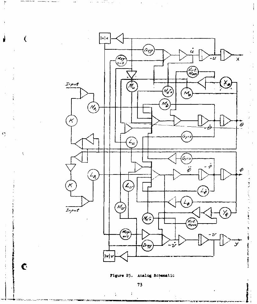
The final configuration of the analog simulation of the hovering

lynamics is shown in the circuit schematic of FigLure25 and the "nominal

configuratior. which was determined to be the beat representation of t"e

C -xperlmnntally-measured model dynamics is characterized by tie derivative

LO

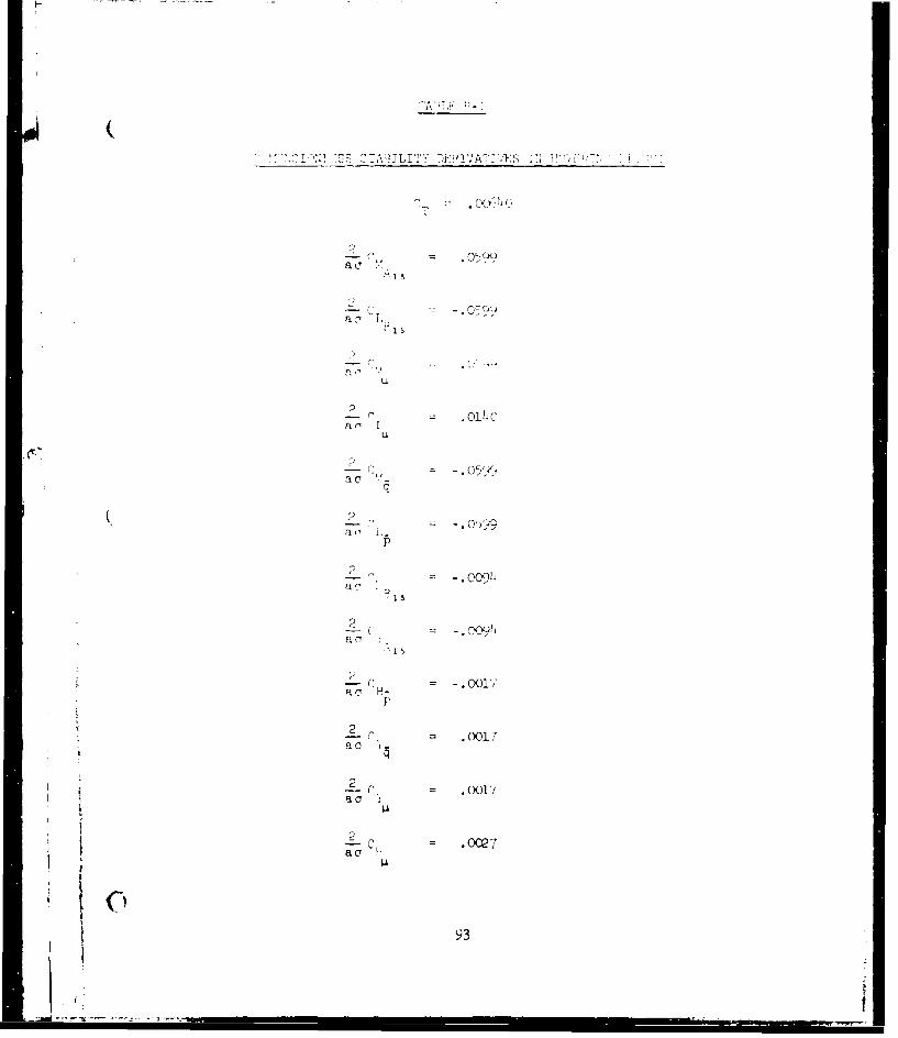
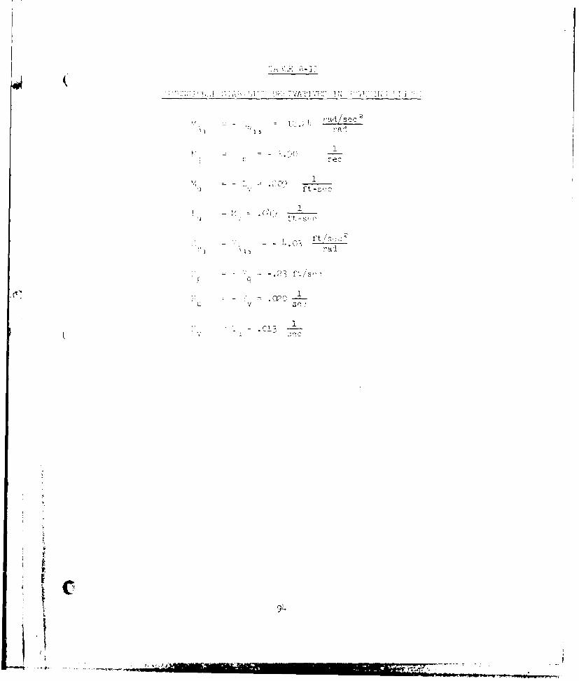
values ljted ir Table R-II. The valles Misted in table 9-II are deteumin"cd

from the ncndimensional values listed in Table B-II and th, e model geometric

and inertial characteristics listed in Table I. In addition t!o, the 'nomInal"

configuration, variatior- in the important derivatives as well as varloas

feedback sta& lization loops were explored and their predominant influences

are here sunmarized.

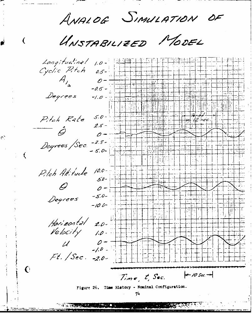
NOMi t ll Clonf'iguration

A time-history of the "r-inal" configuratior RimuLJted initial trans-

ient response is shoea in Figure 26. The unstable characteristic motion is

the ietr'cgraIe precessional mcdc whJch, when fully developed in the limit

cycle, has a period oi approximately 12 seconds. Tnis period is approximately

5• longer than the ex-permertally-rm-sured period of ll.4 seconds and iz ob- 4-

tuineul by using the thecretically-prcd'cted staoility derivative vnlues -

listed in Table B-II. It should be noted that the simu.katton is represents-

tive of t- small amplitude motions of the vehicle. The larger amplitude

motions observed in the e-%perixmental program durirg descent and after retro-

gradc failure may not be adequately represented by the small perturbation

-lvel flight analysis.

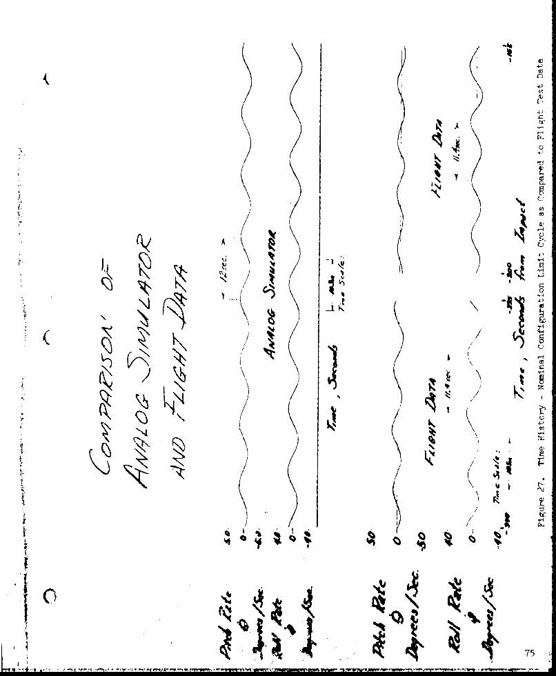
The tgreement between experiment and theory for the "nominal" cnnfig-

urstion is conaideved to be excellent as shc~n in Figure 27, and well with-

in the acr.aracy of the exj'.rimental measurements of model tnrust and inertial "

characteristics. The frequency oi the simulation motion is time dcpendent

until the 2AiOt cycle is fully developed and thp amplitude of t!t simu.1~ion

limit-cycle is depenment upon the chiaracter of tnt input but ln general is

2 4

- ri.-,1' - --

Slarger in amplitude than that observed experimentally except in the descent

portion of the flight. With the exception of drag coefficient, adjustment

of the simulation parameters to shorten the period of the retrograde oscil-

latlon for exact agreement with experiment tends always to increase the

amplitude of the simulation limit-cycle. Owing to the uncertainty of the

theoretical representation of the drag forces and the rather large adjustment

of dra& coefficient required for simulation matching of both period and limit-

cycle amplitude it w-as considered possibly misleading to employ the drag

coefficient as a model matching parameter.

Velocity Stability and Angular Damp ing

The velocity stability and angular dcamping derivatives were varied

simultaneously, maintaining a constant ratio of the two, from one-.ialf their

nominal values to twice their nominal values. Over this range only small

Schanges in modal period (approximately * 4%) and negligible changes in small-

amplitude-mction dampinM were observed, correlating with tie simplified

theoretical p-ediction. This is one of the most important results of the

analog simulation In that the ratio qf theme tyro derivatives is strongly

dependent upon 'he "b!rv-back" effect for yhich only limited experon-mntail

data exist. TZe result that the modal period of the experiMentally-obacrved

rnAel motioms can be approximately matched in the simalation or.3y with a

%anique combination of thlose two derivdtives impIles a htrong corroboratiorn

of the empir'cally determined maitude of the "blaw-brck" effect.

Increasing the velocity stability derivative alorse or decreasing the

Li.42

anguLlar damping lerivative alone produces a predictable change in the

-•riod of tle oscillatory motion and decreases the modal damping for

small anplituder in a similar fashion. The amplitude of the simulation

limit-cycle is also increased by either of these derivative changes in

the direction described.

Drag Coefficient

The non-linear representation of the sphere aerodynamic drag is

responsible for the limit-cycle behavicr of the analog simulation. For

the "nominal" cunfiguration an advance-ratio-independent value of C = 0.6D

was assumed, whdch corresponds to those data available and discussed in

Reference 3. Increasing the simulation value of CD tends to decrease the

osciallatory mode period slightly while also decreasing the Amplitude of

S ( the simulation limit-cycle for a constant input. The amplitude of the

limit-cycle, for a constant step cyclic input, was found to be approximately

proportional to the C value assumed.D

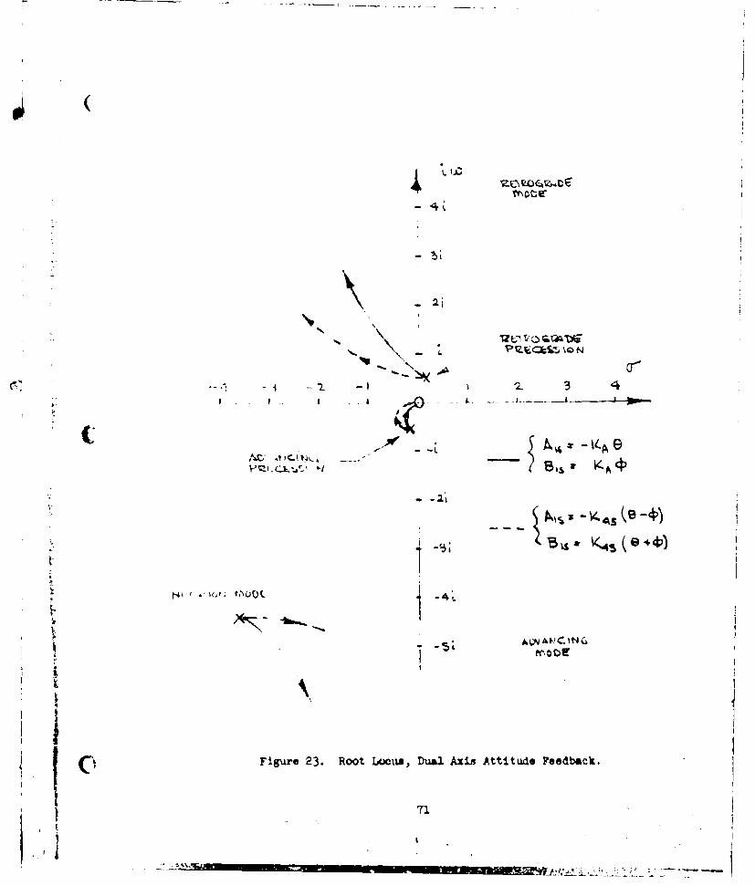
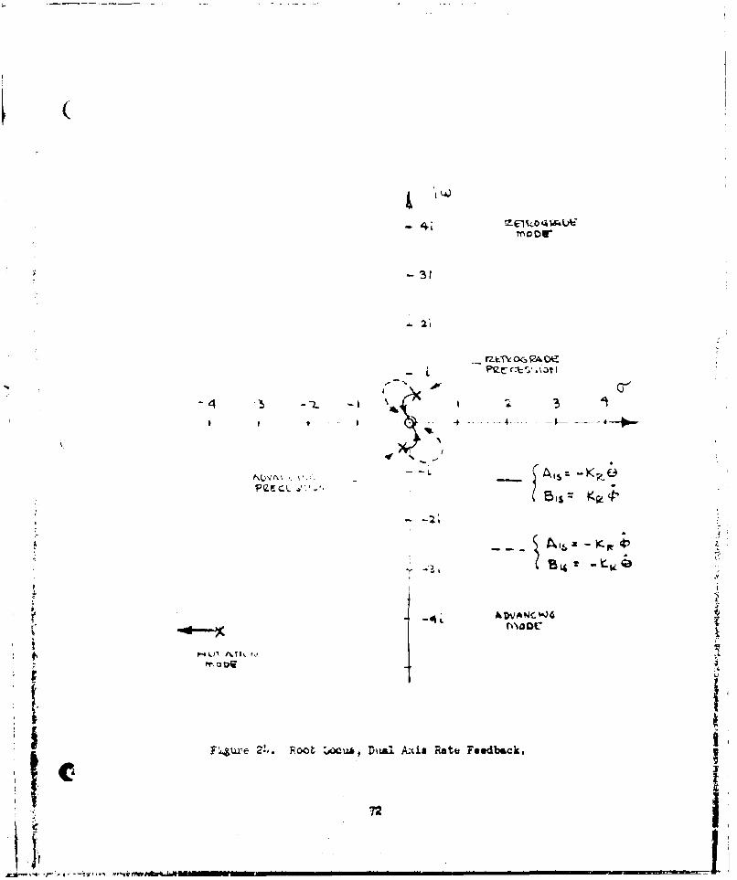
Feedback Stabilization

Various types of feedback stabilization were examined in the analog

simulation and all had predictable influences on the characteristic motion

of the simulated model. As discussed in the analytical section of this

report, the stabilization loop that appears to have a favorable influence

on all the important dynamic characteristics employs a crossed-attitude

feedback as given by the expressions

A1,,- KA (€ 0e).and

Bit A (0

- i " i43

( Physically, this loop closure provides attitude stabilization phased to

lead the characteristic retrograde oscillatory motions by a 1450 phase shift.

Various magnitudes of the feedback gains, K,, were examined in the sim-

ulation study and it was determined that a value of KA = 0.2 %o would criti-

cally damp the retrograde oao$llatory mode and a value of Kx - 0.1 %o signifi-

cantly improved the pilot's ability to operate the simulated vehicle in hover.

A time history of the simulated model motion for KA 0.1 0/0 is presented in

Figure 28.

Piloted Simulation

An analog sl'nulation was set up to accept inputs from the pilot's control

console used to operate the model in the experiwental flight test program.

Various displays were examined from the standpoint of qualifying the fidelity

( of the analoN cimulation and determining requirements for piloting of the

model. For the case of the unstabilized model it was determined that if the

two model attitudes were displayed on a X - Y plotter the pilot felt that

the simulation fairly well represented the model's flight characteritics and

could be flown in hover with a high level of pilot attention and activity.

Any lesser display, such as translational velocity and/or position was

virtually uncontrollable. Addition of attitude rate displays, be means ef

analog meters, to the X - Y plotter attitude display, eased the piloting

task somewbat.

With the crossed-attitude feedback stability augmentation, particularly ±

at the critically-damped condition given by KA - 0.2 %o it was possible for

the pilot to operate the vehiole in hover using the translational position

44I

display only. Performance of the task of translating from one positiou to

another was conriderably improved in this part of the simulation by phasing

the pilot's primary controls, A,. and BlI, so that the intermediate time

(2 to 10 seconds) model translational response was in the direction of the

pilot's stick iiputs. A control input law given by

Aj = A I + .5 13,

and

B1= Blp - .5 Alp

which represents a phasing angle of 260, was determined to be quite acceptable

to the pilot in performing the station keeping and changing task using trans-

lational position information only. As might be expected from control theory,

if the pilot attempts to control the transient oscillation of the model (when

it is not critically damped) using translational. position information only he,(tends to destabilize the motion. At least in the simulation, particularly at

KA 0.2 O/o where the oscillation is nearly critically damped, no difficulties

f -were experienced if the pilot attention was restricted to the longer-term

motions.

It It5 I

cNCcws oWs

Based up-on the experimental and analytical results reported herein

the following conclusions are determined:

1.) An operating model and control system has been developed,

2.) The dominant mode of motion of the AEROCRANE in hovering

flight at any significant thrust levelconsists of mildly

unstable retrograde precessional motion,

3.) Operator on ground encountered difficulty flying slightly

unstable vehicle owing to the lack of motion cues,

14.) Analytical predictions of the model stability derivatives,

when combined with the measured model inertial character-

istics, can be used to simulate accurately the model motions,

5. ) The good agreement between experimental observation and

S ( theory demonstrated in the analog simulation corroborates

both the equation of motion representation and the stability

derivative predictions,

6.) A comparatively simple feedback system utilizing crossed-

attitude feedback can be esployed to stabill,^ the simulator

study and provide for easy pilot control of the model't

position in hovering flight, and

7.) A fully buoyant model would have provided a desirable

safety feature.

1

Cl~46

U-

1I

RECONKDATICKS

1.) An &anlytical model of the forward flight dynamics of the AEROCRANE

should be developed and the dynamic response in forward flight ex-

&mined prior to proceeding with forward flight experimenta.

2.) For further hovering experiments an attitude feedback loop should

be incorporated in the model.

J.%

I t.

L

47

"I ~i

I

SREFERENCES1. Perkins, F. Q. and Doolittle, D.: "AEROCRANE - A Hybrid LTA Aircraft

for Aerial Crane Applications". Proceedings of the Interagency Work-shop on Lighter Than Air Vehicles, Monterey, California, September 19714.

2. Kochin, N. E., Kibel, I. a. and Roze, N. W.: "Theoretical Hydro-mechanics", Interacience 1964.

3, Goldstein, 3.: Modern DeveloMunts in Fluid Dynaics, Vol. T1,

2+, OurLiss, H. C.: "Complex Coordinates in Near Hovering Rotor Dynamics",Journal of Aircraft, Vol. 10, No. 5, May 1973.

5. Goldstein, H.: Classical Mechanics, Addison-Wesley 1957.

6. BRoers, F. J., III: "Hovering Dynamics and Steady-State Forward FlightCharacteristics of the AEROCRANE Hybrid Heavy Lift Vehicle", PrincetonUniversity Department of Aerospace and Mechanical Sciences Report 1275-T,May 1976.

7. Coleman, P. P., et. al.: "Evaluation of the Induced Velocity Fieldof an Idealized Helicopter Rotor", NACA Wartime Report ARR No. L5E1O,June 1945.

8. Harris, F. D.: "Articulated Rotor Ulade Flapping Motion at LowSAdvance Ratio", Journal of the American Helicopter Society, Vol. 17,

No. 1, January 1972.

9. Vertol Division of the Boeing Company: "Experimental Programs ConductedUnder the U. S. Army Cast Loan Agreement, Vol. I Static Tests on a FullScale Boeing-Vertol 76 Rigid Propeller." Report No. R-339, June 1965.

10., Gessow, A. and Myers, G. C.: Aerodynamics of the Helicopter. TheMacMillan Company, New York, 1952.

Ii. Miller, R. H.: "Rotor Slade Harmonic Air Loading", IAS Paper No. 62-82,Presented at IAS 30rth A•nnual Meeting, New York, N. Y., January 22-24,1962.

12. Payne, H. E., III- "Propeller Effects on Stability and Control ofVTOL Aircraft", Aerospace Engineering, Vol. 19, No. 3, March 1960.48I

0IU "

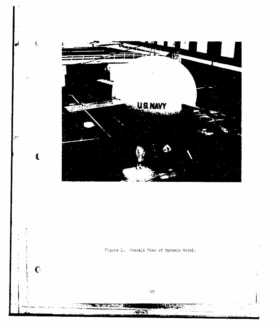
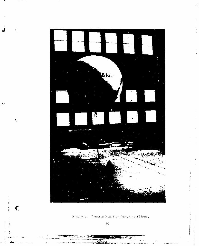
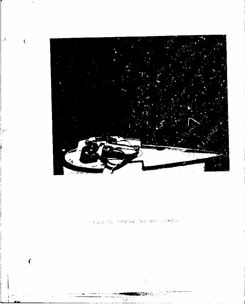
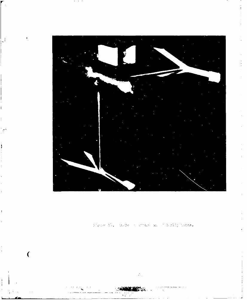
Figure 1. Overall View of Dynamic Model.

IC

& I~~C~ vmamfic2 ModeliIn ý!cvering lI~t

50

---- ~ ~~~~~~~ ------------ ________________

57'. ~_ _ _ _ _ _ _ _ _ _ _ _

6.(.6Z 5A

'•.- •Z _ _ _ _ _ _ _ _ _ _ _ _

,•., _4.07rM PO &

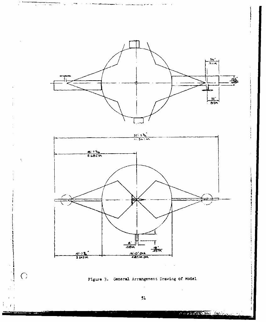
IC Figure 3. General Arrangement Drawing of Model

51

- �¾-� n>l

(

- -------------.-- I 14 - -'1

d - ,- ---- - - -- - - -- -

* .�r-----'-- wr- "rr-r--'� -

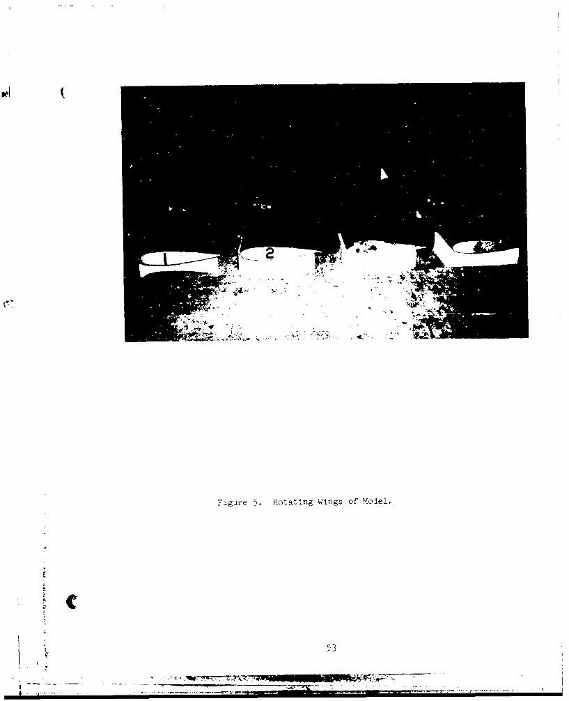
Figare 5. Rotating Wings of Model.

V 513/ --

4'

(

- - -----.--- - - ±

�i�-- - _________

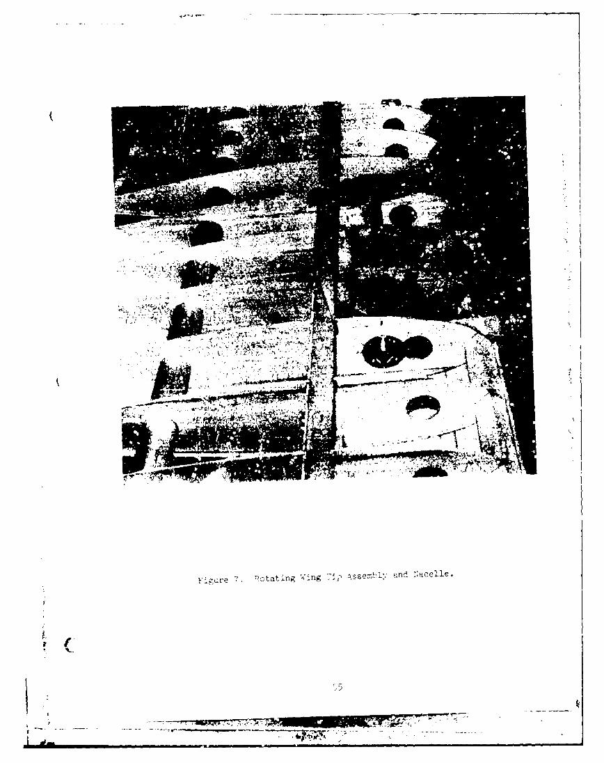
F-taF~re -. Patating Wing Tip sebl n Nacelle.

F,7

757-

I'

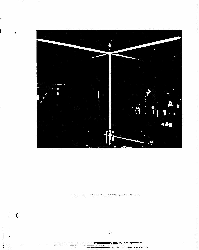
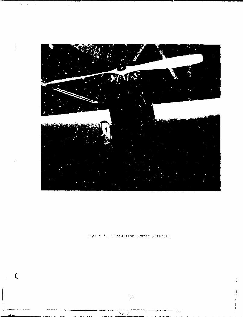
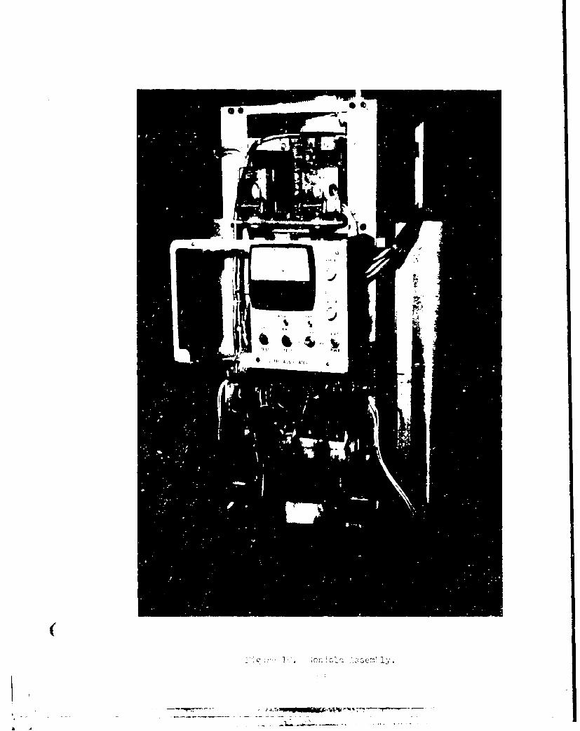
FIgure 1 reels ion 3y�tp� sembi

(

V

LMa ¼

(

-�& Ma

(.2

....l ....-..

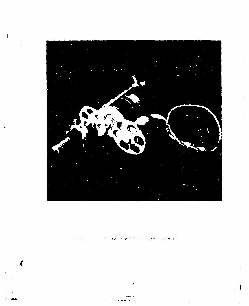
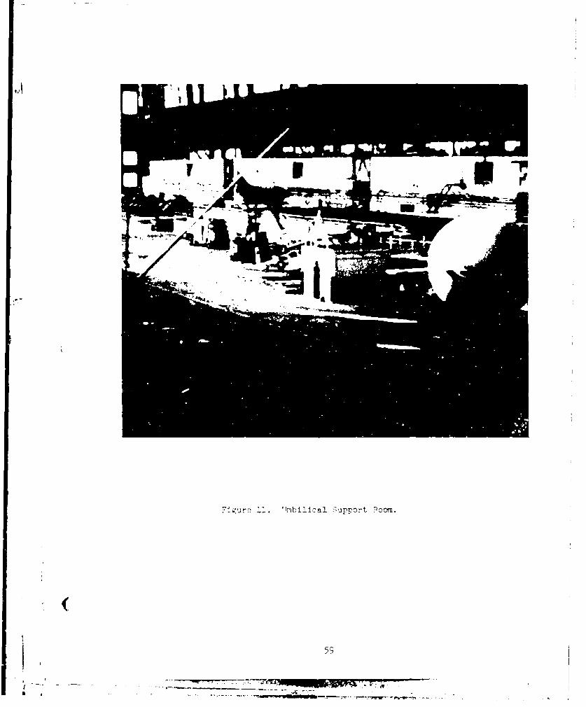
F~ue11. "TmbilIcal Sýupport 9ýom.

I 59

I

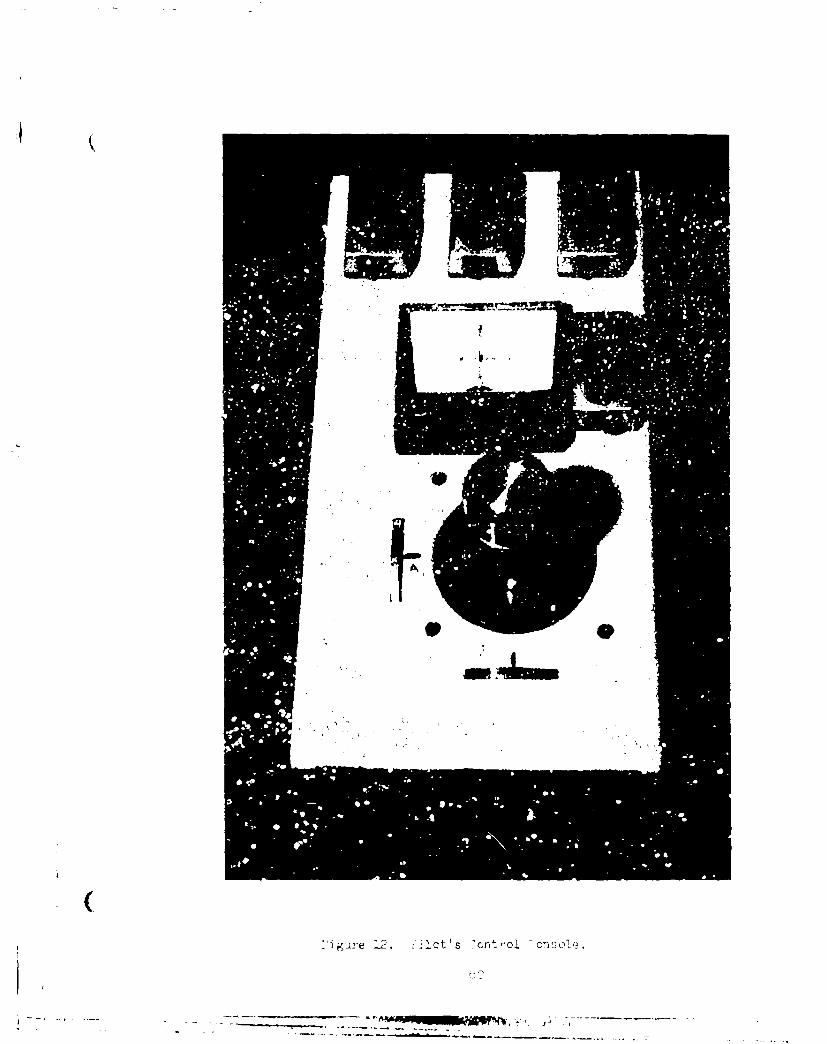
(:'tgure L2. lot's Ynt"ol 7o�vo½.

C-

7 - -

Wi

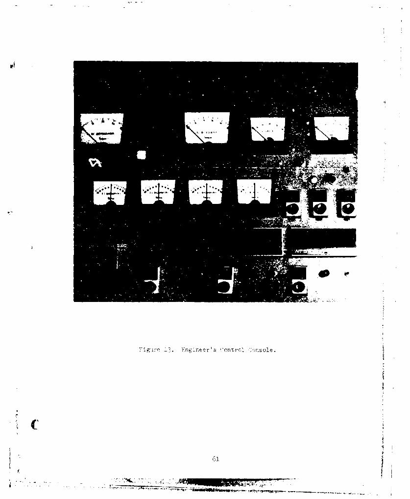
YI�iro 13. Kogineer's Control Console.

i

I

iC'

K Ia VAi*:-j. - - -

IV

1'. --

(

I I

AAc

oz ~ ~ ~ ~ 4 I iI41r l-

Ka ---

/T

k. .14 vo,)g1ý

Figre15.Axs ystm ndNowcau

~6

-3-

4 -4%

-APO

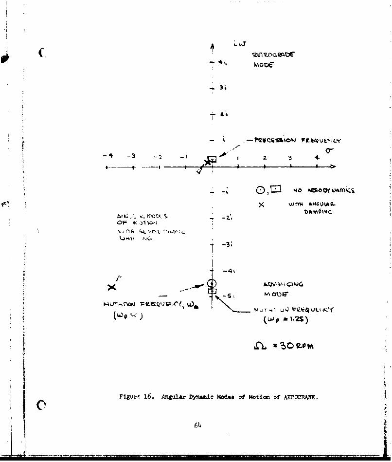
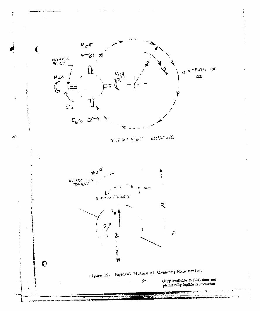
Figure 16. Argular DYnamic Modles of Notion of AEROCC1UA.

06

~-1

.3D

4-.-.

4-4

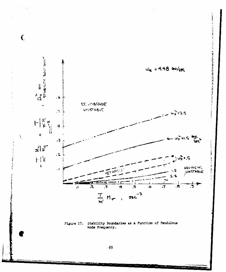
Figure 17. Stability Bounaries as a Function of' PendulousMode Feuny

I6

Copy c'vcdlabla to DDC C;c- n(,,

parmit fuTlely e~~ raproI.,ý;t-ý

(

K N-

) "

X

661

( i

Al-

AbAbT 16il

* rouco

711 /r

fV A./ APT)~ INI.T'Aý- zi~fowse

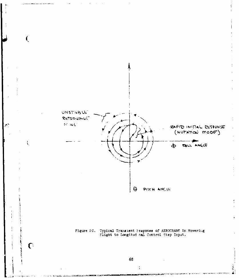
Figure 20. Typical Transient YemponRe of AEROCRAJNF in HoveriihgFlight to Longitud naJ. Control Step input.

68

k ,OS C- Co _ .•h--•- = ,312

-V-

Mcvl t Ysh

S€c, 40 .S

• .00 .01

N - t •- p ," 1

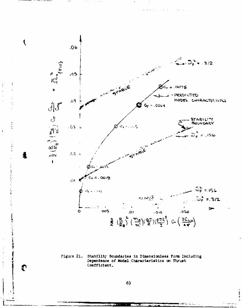
Fiur 21 Stbltounare .1 Dimeniolss For Includin

D e f C c i TCoef-ficient.

2 69

Cp1-

iiSFigure 21. Stabllitr" Boundaie. in Dimensionless Form Irncluding

SDependence off Mode CI'ara~ctriutica cvn Thust• Coetlicient.

l6

£ 4 _- _ .II aa . --

(-

10 T74L5

> /U P-- 6r 41 I u

,-OI 0.2. 03

I.I

V2

Figure 22. Dimensionless Stability Boundaries, Thrust Coefficient

vs. Dimensionlese Pendulous Frequency 8Suared.

170

F(

-4?

.I . .. . .1__ T

11

4 L

Fiue23. Root L~cous, Dual AxiB Attitude Feedback.

(

-31

-21

rzt~k WOG 9A C- -L-

-K

-441 -Kit-~'

V.,

Y 4ux ze 2!, Root. :"ub, DtmlZ Axts Rat~e Feedback.

r• 72

.- '-,•",,,"•. •] •-•z',-', ,-•-t-r /,.'lr' !l- 11¶ A- I - K '•' E' '-''

A40

,4z, -

AtA

Figure 25. Analog 8chematIc

73I

7. -ý

'i -E

-Z6'-

.....e e ..e c . I

ý7 .7

77Ae Z $"77

Figure 26. Tim HistorY NcminrA1 Configuration2.74

i7

-41

4-)

4)

0

kr-4

43,

NIS.

* 75

vi -A N, ,V

-oov4f Si"-44L 1 I H- < -i 1)

69 0

,,l,17 WV ITel K/K7V -

'IIle /a, c

~ii;Ure 28, Tim Y{istory -Crossed Attitude i~ilbsc), KA '(..%

7b P~

APMENDIX A

ROTOR AERODYNAMICS

Ti! this •ect~on the contributions of the rotor to the aerodynamics

oi' ýhe vehicle are developed. It is assumed in the following development

that the rotor blades are infinitely stiff in flapping and have zero

coning angle. It is also assumed that the blade element inflow angle is

sml-l and that the lift curve slope of the blades is constant. A shaft

axis system is used as the reference frame for development of the rotor

forces.

The only unusual feature as compared to conventional helicopter

articulited rr.tor analysis is the inclusion of first harmonic components

of the invluced v!elocity. There are considered to be two sources of

harm.onic inffcr,

The first arises from the fact that as the vehicle translates

fo:c!ardt, t.e wake of trailing vorticity will be "blown back" causing a

variation in Tiduced velocity along the longitudinal axis of the rotor

(7)plane as pointft oukt by Coleman many years ago . The importance of

this effect is clearly shown for an articulated rotor in the experimental

data prsýented by Harris' '. "fris effect will be discussed at aome

leýngth later ia this section.

- The seconl source of first harmonic induced velocity variation is

a ilrect result of tVc fact that the rotor blades do not flap. Thus the

effect of a chAnge in anyaerodynamic condition of the rotor (cyclic pitch,

pitch rate.) iwrch produces a harmonic lift variation, rather than being

7

cancelled out by a flapping response as would be the case for an articulated

rotor, remains. As a result it would he expected that a harmonic induced

velocity variation would be produced. Limited experimental data(9) on

a rigid pro: eller have indicated that this effect is quite large and

should be accounted for.

'he blades employed on the model are untwisted and untapered and this

Is reflected in the aerodýmamic model. For simplicity, the constant part

of the induced velocity is assumed to be independent of radius although

this would not, s'rictly speaking, be true for untwisted rotor blades in

hovering

The rotor forces are developed using a shaft axis system with a

relative wind orientation. That is,the longitudinal force F is parallel

to the relative wind and the side force Y is perperlicular to the relative

wind. Thus the follcwAng transformations must be considered to develop

the velocity perturbation derivatives as shon in Figure A-1.

In coefficient fcrm

U v

CM -C + +C

y ( S'w u SW U ýu v

C c ~ ~ - (A-2)

M

78

SLg Ls VW477 sw ý +

Owing to the wind axis formulation, the wind oriented forces and moments

will be only a function of p. Since hovering flight is of interest the

equilibrium or trim values of all the forc!es and moments are zero as well

as the initial values of the velocities v and u. Therefore, it can be

seen that the following relationships hold for the translation derivatives

in the 'r :y axis system.

3S HS) He '-s'w - s'W

eYe By s CYe 3H w

aCM 3C acM aCLN, L 5s (A-3)

These symmetry telationsnips are helpful in simplifying the dynamic analysis

as shown elsewhere in this report.

Now the rotor forces and mcmento in the shaft/wind system are developed.

i Assuming tVat the inflow angle is small the expression for the average

forces rird moneits expresed in terms of the lift and drag acting on a

blade element a, eSb 2in

T g $ o dLB'W 2r 0 Re

H b 2 Ra

79

.Y 2tt (dD - 0 dL) cos *

2rT R-w j r dL cos,

S~w 2,rJ 0 Re

L r bS,w 0~ S Reds

Th- lift and drag on the blade element can be expressed as

dL = 2 p (nr) 2 cdr a ae

dD = 2 p (or) cdr 6

Tr•e angle of attack of the blade elempnt is

a e +0

• re

S= e A A cos V - 3B, sin*

an:• (tb-6)

+ A sin* +A cost___S C

X average itnELf- tiiroug'a the rotc, u,'d is driflned as

T]ie advance ratiG

The he'monic ii•lo components represented by A and A arise de to3 C

pitch rnte and roll rate and as a result of the harmonic inflow; cw(- )ents

discusseu aoove. They =y rr expressed be.

S O8

*;!~. ~ - w ~ t ? . ' ¶ r r , ,- . ~ ' - -' .'' ' f - - r

s (A,-8)

Ac x +xD

where • and s a'e the pitc0 and roll rates non dimensioralized by rotor

RPM, X8 is the "blow back" effect and XL and XM represent the harmonic

Induced velocity compcnents produced as a result of the harmonic lift

variations.ý

Combining these expressions and performing the Integrations indicated

by equations (A-4) and nondimensionalizing the forces and moments, the force

and moment coefficieints a,,e

2CT 2

_ 3 +- - s - s B23 ) . 2

tA-9)

2-(- " ( + XL ( 1

2C 6" .

ac~~ 7'a 0 3s

+-' £'.K (i - x) -X L. 2.

+ +

iS

2 2

X L I-1ý

• " • --- :- •.*-•..,.,-:,, .,,-,-.-,•_- -T " • , ,'1'. .• • --- -''-- "2

2

2 X

+ + -m + - I ý 1 \

2"2

2 - x2

2 2n

2C L 3B i V-' = -H - ,

\is the dimensionlei3 locatic.- of ttre root of thc- rot.)r hlede. Th e

\'ar-aticn of th.A harmnonic inflow~ ervponentt, with radius has heen taken

as foll~ow. Th,- c'oseje ccaponent 1j, hias I-epn assumed to vary linearly

with rncdius following Coleman, i.e., X9 )Ix. Since there is no

sinpl1ý tý-,cry to deteimine the vzri.tWon vf X and XLwith rttdius,

ii' simrlicit~y they have becn sstnied to be indep-ndent of radiuis.

S~ince vn~r'aaiues ar,ý determinee' espirically by cocparisoii Vith _ imiter!

pep-rim~ntal drita it in considered that this &sstupt!efc is satisictory.

M,¶m. ntuni theory is usri to deternine >.s

)s = ('ý. -1o))

r:ute that in thr above all of the coefficients as well as the solidity

are defined co ltotal radius.

The harmonic inflow components \ and XL are determined by assuming

that the magnitude of these components is proportional to the aerodynamic

(!4)moment acting on the rotor Thus, it is assumed that

2 CM 2CLL IA-ila)-- - X' ='J act

whpre J is a corstant of proportionality determined from experimental data.

PReference 9 contains experimental data showing the moment produced by cyclic

pitch application on a small rigid propeller and these data are used to

determine the magnitude cf J. Figure A-2 shows the experimental data.

Placing the first of the expressions above in the equation given above

for C and calculating the rate of change of pitching moment with cyclic,

with x 0, for a prop1eller,

dC 1

Rc &* dj 1 (A-12)

The experimental data present in Figure A-2 lies between values of 3

corresponding to rigid and non-rigid wake assumptions in Reference 11.

3 ac 3 aIT I .! < j <

so tr average of these two values is selected. Therefore,

C83

! 'I

Iac

"KO

'Jsing th'.- relal ionship, the expressit:.: for the hub moments become

+___ 1_aI12 \7 1 >

1 c. 22T ( -" 3 - -- -

- g (�1- ~4 + ( - (1- \3 -L(

It can be seen that this effect reduces all the pitching moment derivatives

by the same factor.

(The remaining quantity to be prerdcted is X . The theoretical de-

pendence obtained by Coleman is shown in Figure A-3. Since the interest

here is near hovering flight the linear portion of the curve near hov'ciing

may be used. This can be approximated by

- • (A,-15)

Harris' experimental data show that Coleman's result given in (A-15) as

well as a number cf other theories are in error by about a factor of two

in predicting the lateral flapping of an articulated rotor at low advance

ratios (see Figure 11 of Reference 8). This is in part no doubt due to

the fact that Coleman assumes a linear distribution of X9 along the longi-

tudinal axis such that

X x (A-15)

84- C

~~L L

ani that lateral fl.apping depends upon the integral

He a2 (X (A-16)

Similarly '.t ma: bc 5hcý-n that the hub moment on a rigid propeller

prrluced by :hi• effect depends on the same integral, and as a result

is sensitive tc the variation of \§ near the tips. Data for the pitching

moment acting on a rigid propeller are presented in Reference 12. Applying

Coleman's thec:;, to these data shows good agreement without adding the

effect of the ,rmoni- Inflow due to the j factor. This effect is of

_ lse not present in }Hrris' data since a fully articulated rotor was

emjiuyed. if the harmonic inflow effect is included in the prediction

of the prro elln- hub moment, the prediction is in error by about afah'tor of two. Fhus, good agreement with the magnitude of the"blow back"

c-ff•ct •+ -btai-ed for both the articulated rotor and the rigid rotor

If toe value g~ven by Coleman's theory is doubled and the J-factor

deter-mined from the experiments of Reference 9 is used. Therefore in

the following

X " (A-l)

The stability derivatlve6 can now be calculated. Equation (A-17)

gives

The results are given for hovering flight although the expressions

developed and presented in equations (A-9) are generally applicable to

forward flight. The approximation given by (A-17) applies only near

hovering as does the equation for the J-factor given by equation (A-13).

89

The thrust is found to be constant as a result of the linearization

and as a consequence X is constant, since a is defined as 0 for thean sacnsqec s S

ho-v)vlIrig trim condition.

The stability derivatives are as follows. Interestingly all of the

dimensionless pitching moment derivatives are equal with the exception

of signs, That is

2 CM 3C C CL

2_ _ 2 F M 2 ()-.M, sw= 2 sw

ar- A15 a 7 s a c ac a,(

-n? rclling nm'nent derivatives are

2 c CL 1' / -'4

Sl + a-c2 1 - (1'

2 S'•= 2 8 W

anl

a,

The body axis moment derivatives are given by relatiomsnlips A-3

The force derivatives are as follows:

2 SSWa C7 2a 2

is+ I+2

2 +'HS XS 20~-xa! cT -) ((- 22)

s ~aa

+ _ _ [ O ,+ 2 _ _ _ _

2 + 2~ lSW+ ( \]

a( 3 1 s a c r ~ ss

2 MS

S 8

acc ~

2~ 2~ -\ \ w

a y s L4 0 4 o + Ns (1 -c 3AI

For --onveienc~e 'n --alculation note that t le followng equalities hold.

acMccM W M m'4 6 L SacL w

S~w - S,w S, -

S - S~W ,

aB S a .

-~LTh1OFVL4 5

cil

Figure A-1. Definition of Rotor Forces and moments.

C• 88

f4

11

01

(a,,'A

W1 I •lI "- -

_- k

a.3- - -•I. -" 0-

C-C,

Figure A-2. Coparison of Theory &nd E/periment for Control

• . Effectiveness of Rigid Propeller.

fr t

OAO" joaervout~

It~

I a )

14 0

/C.lii

1~ 1 I).. -i "

C) 0

4-

/ 1 0 •'7

I

90

i -Oinr tb i ity ne vni 's rrýItcA mcd k:, t w r'

*1 as *)n th'j*1veop- rnjix

jotie:.mo-lThI geo)metry and 'ocorating ccmrd±4Uco:s are '~'

010

V- l4 ~ i slugs/*t0

i Iit io tooe il ue frthe 'h1-,c baok' rffect as vivel'. ;~

I .K": as twice tl - valt- given by the th-ory of Roferen-oc ao irtdicattci

1 'a 'y ~m~no1 It-iýt of T,-fprencp'o 8 and 12.

uypor-I i c-al± 0', 0. a for thc hnrmonic! iirfiow effcct j was 'a-sed

t8 ' oxpTI-ir~nf~i ±1uta 'of :)ef.-rence 9 as

Tne .llmensicnilpss stability derivatives are prese:ited -'n Tanle P-I

anI th:_ dimensior,ul dei 'vatives are pres '.nted in Tahle R-II.

The moment d.erivat-ives are the hub moments only since in all cases

the moiments due t,) the i,.-plane forces are less than two per'cent -,f

91

( 'net.due to th inr-pl an'? f -'Q-sr'-s'1tir~g franm

I I'1'""1 rri 'a =mall amo'u. 1 at' C~oro1 f or] f7!--!

ptias- : t !i caonT.l ari en th-erefore was neglec-ted in. the, c otnr ter

anal., Ijs0

I5 -F,3B t P th,& 'mall estimated magnitude of, te cý ontrol

-''rintives they '"-e neglecteýd In t~he disclus:ion or.- stabilit\

I'.

I-ý

(A

: • C = O :

1 54

p

a,,

± C'

[L

-t "

2_ 10017~fanC

c' - 0Q07

a,0 '-

p

S

an

'15

.. 2'-C H -. 0011

2_C. = .0017

± c, = .0017

93

' t

T V ' 12 T 1

1 1

'a~f e, Ct S

- - > ft

X1~ ral

C ~ - 23 ftsr

9~4

s DISTRIBUTION

ComuanderNaval Air Systems CommandWashington, DC 20361Attention: AIR-954 (1 copy)

AIR-03 (I copy)AIR-03P3 (1 copy)AIR-03P32 (1 copy)AIR-320 (1 copy)AIR-5301 (I copy)

Chief of Naval OperationsDepart=ent of the NavyWashington, DC 20350Attention: OP-987 (1 copy)

OP-506E (1 copy)

Cxonianderhaval Facilities Engineering Comand200 Stova~l StreetAlexandria, VA 22332Attention: NFAC-03 (4 copies)

SuperintendentNaval Postgraduate SchoolMonterey, CA 93940Attention: Library (i copy)

CommanderNaval Air Development CenterWarminster, PA 18974Attention: Code 31P3 (15 copies)

Commander (

aevid W. Taylor Naval Ship Research andDevelopwnt Center

bethesda, ND 20034Attention: Director, Aerodynamics Laboratory (1 copy)

Chief of Naval Research000 Worth Quirny StreetArlington, VA 22217Attentions Xr. T. Wilson, Code 461 (1 copy)

CcmwLnderNaval Weapons CenterChina Lake, CA 33555Attention: Acrodynmias branoh, code 4061 (1 copy)

UCi4g (2)

4

DISTRIBUTION: (Continued)

Air Force Flight Dynamics Laboratory

Air Force Systems CommandWright-Patterson Air Force Base, OH 45433Attention: Library (1 copy)

CommanderU. S. Arwy Aviation Systems ComandSt. Louis, MO 63166Attention: Library (1 copy)

DirectorU. S. Army Air Mobility Research and Development LaboratoryAmes Research CenterMoffett Field, CA 94035Attention% Library (1 copy)

DirectorEustis DirectorateU. S. Army Air Mobility Research and Development LaboratoryPort Eustis, VA 23604Attention: Library (1 copy)

Mr. Robert Smith (1 copy)

DirectorLangley Research CenterNational Aeronautics and Space Ad&inistration

Hampton, VA 23365Attention: Library (1 copy)

DirectorAmes Research CenterNational Aeronautics and Space AdipinistrationNoffett Field, CA 94035Attention: Library (1 copy)

Dr. Mark Ardema (1 copy)

Director of Forest Products and Eriginaering ResearchU. S. Department of Agriculture# Forest ServiceWashington, DC 20250(2 copies)

j SecretaryDepartment of Transportation400 7th Street, S.W.Washington, DC 20590Attentionj Assistant for Aeronautical RPD (I copy)

2¢I

DISTRIBUTIONs (Continued)

DirectorNJational Aeronautics and Space Administration600 Independence AvenueWashington, DC 20546Attention: Director, Study and Analysis Office (1 copy)

7M

I

I13

(• 0* - r r


Recommended