SoftMoW: Recursive and Reconfigurable Cellular WAN Architecture Mehrdad Moradi † Wenfei Wu ‡ * Li Erran Li ? Z. Morley Mao † Bell Lab, Alcatel-Lucent ? University of Michigan–Ann Arbor † University of Wisconsin–Madison ‡ ABSTRACT The current LTE network architecture is organized into very large regions, each having a core network and a radio access network. The core network contains an Internet edge com- prised of packet data network gateways (PGWs). The radio network consists of only base stations. There are minimal in- teractions among regions other than interference management at the edge. The current architecture has several problems. First, mobile application performance is seriously impacted by the lack of Internet egress points per region. Second, the continued exponential growth of mobile traffic puts tremen- dous pressure on the scalability of PGWs. Third, the fast growth of signaling traffic known as the signaling storm prob- lem poses a major challenge to the scalability of the control plane. To address these problems, we present SoftMoW, a recursive and reconfigurable cellular WAN architecture that supports seamlessly inter-connected core networks, reconfig- urable control plane, and global optimization. To scale the control plane nation-wide, SoftMoW recur- sively builds up the hierarchical control plane with novel abstractions of both control plane and data plane entities. To enable scalable end-to-end path setup, SoftMoW presents a novel label swapping mechanism such that each controller only operates on its logical topology and each switch along the path only sees at most one label. SoftMoW supports new network-wide optimization functions such as optimal routing and inter-region handover minimization. We demonstrate that SoftMoW improves the performance, flexibility and scalability of cellular WAN using real LTE network traces with thousands of base stations and millions of subscribers. Our evaluation shows that path inflation and inter-region handovers can be reduced by up to 60% and 44% respectively. Categories and Subject Descriptors C.2.1 [Network Architecture and Design]: Distributed networks; C.2.5 [Local and Wide-Area Networks]: Ap- plications * This work was performed when Wenfei was an intern at Bell Labs and was supported by NSF grant CNS 1218668. Permission to make digital or hard copies of all or part of this work for personal or classroom use is granted without fee provided that copies are not made or distributed for profit or commercial advantage and that copies bear this notice and the full cita- tion on the first page. Copyrights for components of this work owned by others than ACM must be honored. Abstracting with credit is permitted. To copy otherwise, or re- publish, to post on servers or to redistribute to lists, requires prior specific permission and/or a fee. Request permissions from [email protected]. CoNEXT’14, December 02-05 2014, Sydney, Australia Copyright 2014 ACM 978-1-4503-3279-8/14/12 ...$15.00. http://dx.doi.org/10.1145/2674005.2674981. Keywords Cellular Networks; Software-Defined Networking; Hierarchi- cal Controllers 1. INTRODUCTION The current LTE network architecture is organized into very large and rigid regions. Each large region has a core network and a radio access network. The core network contains an Internet edge comprised of packet data network gateways (PGWs). The radio network consists of only base stations. In this architecture, there are minimal control plane and data plane interactions among regions other than distributed interference management at radio access networks and limited coordination for mobility (e.g. no inter-PGW mobility [25]). All users’ outgoing traffic must traverse a PGW and possibly go through the Internet. This rigid architecture is becoming harder and harder to support new trends of mobile traffic. First, mobile applica- tion performance is seriously impacted by the lack of Internet egress points per region. Specifically, as shown by a recent study [24], the lack of sufficiently close Internet egress points is a major cause of path inflation, suboptimal routing, and QoS degradation in large operators. Second, the continued exponential growth of mobile traffic puts tremendous pres- sure on the scalability of PGWs. Third, the fast growth of signaling traffic known as the signaling storm problem [4] poses a major challenge to the scalability of the control plane. Rather than organizing mobile wide area networks as rigid regions with no direct traffic transit, we argue that cellu- lar networks should have a seamlessly inter-connected core network with a logically centralized control plane. The inter- connected core network should consist of a fabric of simple core switches and a distributed set of middleboxes (software or hardware). The control plane directs traffic through effi- cient network paths that might cross region boundaries rather than exiting to the Internet directly from the origin region. The control plane should also globally support seamless UE mobility and optimize the performance of mobile traffic. For example, mobile traffic routing should be globally optimized; regions should be reconfigured to adapt to its workload. Such an architecture raises unique challenges in scalability in comparison with data-center networks [12, 20] and inter- data center WANs [16, 15] since the cellular WAN has its own unique properties and challenges. First, the logically centralized control plane needs to control tens of thousands of switches and middleboxes, and hundreds of thousands of base stations in the data plane. A control plane with many controller instances in one data center cannot effectively han- 377
Transcript
SoftMoW: Recursive and ReconfigurableCellular WAN Architecture
Mehrdad Moradi† Wenfei Wu ‡∗
Li Erran Li? Z. Morley Mao†
Bell Lab, Alcatel-Lucent? University of Michigan–Ann Arbor† University of Wisconsin–Madison‡
ABSTRACTThe current LTE network architecture is organized into verylarge regions, each having a core network and a radio accessnetwork. The core network contains an Internet edge com-prised of packet data network gateways (PGWs). The radionetwork consists of only base stations. There are minimal in-teractions among regions other than interference managementat the edge. The current architecture has several problems.First, mobile application performance is seriously impactedby the lack of Internet egress points per region. Second, thecontinued exponential growth of mobile traffic puts tremen-dous pressure on the scalability of PGWs. Third, the fastgrowth of signaling traffic known as the signaling storm prob-lem poses a major challenge to the scalability of the controlplane. To address these problems, we present SoftMoW, arecursive and reconfigurable cellular WAN architecture thatsupports seamlessly inter-connected core networks, reconfig-urable control plane, and global optimization.
To scale the control plane nation-wide, SoftMoW recur-sively builds up the hierarchical control plane with novelabstractions of both control plane and data plane entities.To enable scalable end-to-end path setup, SoftMoW presentsa novel label swapping mechanism such that each controlleronly operates on its logical topology and each switch alongthe path only sees at most one label. SoftMoW supports newnetwork-wide optimization functions such as optimal routingand inter-region handover minimization. We demonstratethat SoftMoW improves the performance, flexibility andscalability of cellular WAN using real LTE network traceswith thousands of base stations and millions of subscribers.Our evaluation shows that path inflation and inter-regionhandovers can be reduced by up to 60% and 44% respectively.
Categories and Subject DescriptorsC.2.1 [Network Architecture and Design]: Distributednetworks; C.2.5 [Local and Wide-Area Networks]: Ap-plications
∗This work was performed when Wenfei was an intern atBell Labs and was supported by NSF grant CNS 1218668.
Permission to make digital or hard copies of all or part of this work for personal orclassroom use is granted without fee provided that copies are not made or distributedfor profit or commercial advantage and that copies bear this notice and the full cita-tion on the first page. Copyrights for components of this work owned by others thanACM must be honored. Abstracting with credit is permitted. To copy otherwise, or re-publish, to post on servers or to redistribute to lists, requires prior specific permissionand/or a fee. Request permissions from [email protected]’14, December 02-05 2014, Sydney, AustraliaCopyright 2014 ACM 978-1-4503-3279-8/14/12 ...$15.00.http://dx.doi.org/10.1145/2674005.2674981.
1. INTRODUCTIONThe current LTE network architecture is organized into
very large and rigid regions. Each large region has a corenetwork and a radio access network. The core networkcontains an Internet edge comprised of packet data networkgateways (PGWs). The radio network consists of only basestations. In this architecture, there are minimal controlplane and data plane interactions among regions other thandistributed interference management at radio access networksand limited coordination for mobility (e.g. no inter-PGWmobility [25]). All users’ outgoing traffic must traverse aPGW and possibly go through the Internet.
This rigid architecture is becoming harder and harder tosupport new trends of mobile traffic. First, mobile applica-tion performance is seriously impacted by the lack of Internetegress points per region. Specifically, as shown by a recentstudy [24], the lack of sufficiently close Internet egress pointsis a major cause of path inflation, suboptimal routing, andQoS degradation in large operators. Second, the continuedexponential growth of mobile traffic puts tremendous pres-sure on the scalability of PGWs. Third, the fast growth ofsignaling traffic known as the signaling storm problem [4]poses a major challenge to the scalability of the control plane.
Rather than organizing mobile wide area networks as rigidregions with no direct traffic transit, we argue that cellu-lar networks should have a seamlessly inter-connected corenetwork with a logically centralized control plane. The inter-connected core network should consist of a fabric of simplecore switches and a distributed set of middleboxes (softwareor hardware). The control plane directs traffic through effi-cient network paths that might cross region boundaries ratherthan exiting to the Internet directly from the origin region.The control plane should also globally support seamless UEmobility and optimize the performance of mobile traffic. Forexample, mobile traffic routing should be globally optimized;regions should be reconfigured to adapt to its workload.
Such an architecture raises unique challenges in scalabilityin comparison with data-center networks [12, 20] and inter-data center WANs [16, 15] since the cellular WAN has itsown unique properties and challenges. First, the logicallycentralized control plane needs to control tens of thousandsof switches and middleboxes, and hundreds of thousands ofbase stations in the data plane. A control plane with manycontroller instances in one data center cannot effectively han-
377
dle the signaling load (e.g., connection setups and handovers)from hundreds of millions of subscribers distributed through-out a continent. Second, without global network states anda single controller exerting control, it will be hard to performnetwork wide routing optimization and inter-region handoverminimization.
To address these problems, we present SoftMoW, a scalablenetwork-wide control plane that supports global optimiza-tion and control plane reconfiguration. SoftMoW makes thefollowing contributions.• First, SoftMoW recursively builds up the hierarchical con-
trol plane with novel abstractions consisting of both controlplane and data plane entities. Key to our SoftMoW ar-chitecture is the controller. It is designed to be modularwhich consists of the network operating system (NOS),operator applications and the recursive abstraction appli-cation (RecA). NOS provides core services such as routingand path implementation. NOS does not handle cellu-lar specific functions. Operator specific functions (e.g.mobility management) are implemented as applicationson top of NOS. All recursive abstraction functions areimplemented in RecA.
• Second, to enable scalable end-to-end path setup, Soft-MoW presents a novel label swapping mechanism such thateach controller only operates on its logical topology andeach switch along a flow’s path only sees at most one label.This new mechanism reduces the states in the switches.
• Third, SoftMoW designs new network-wide optimizationfunctions such as optimal routing and region optimizationto minimize inter-region handover.
• Fourth, we demonstrate that SoftMoW improves the per-formance, flexibility and scalability of cellular WAN usingreal LTE network traces with thousands of base stationsand millions of subscribers. Our evaluation shows thatpath inflation and inter-region handovers can be reducedby up to 60% and 44% respectively.
2. SoftMoW DESIGN OVERVIEWSoftMoW’s goal is to design a scalable cellular WAN ar-
chitecture (both the control plane and data plane) to enablenetwork-wide optimizations. We introduce the components ina SoftMoW network, the design challenges and our solutions.
2.1 SoftMoW ComponentsSoftMoW does not require expensive, inflexible and special-
ized devices (e.g., PGWs and SGWs) that integrate controland data plane operations with middlebox functions. Soft-MoW does not change the LTE protocols used in the userequipment (UE) and the protocols between UE and basestations. SoftMoW has the following high-level architecturalcomponents.
Nation-wide inter-connected core networks. Soft-MoW distributes and inter-connects programmable switchesnation-wide. The network in one region should have enoughegress points through a subset of the switches. An egresspoint can connect to other regions of the same carrier, othercarriers’ mobile networks, Internet service providers or con-tent providers at peering points to exchange traffic. Thiseliminates the internal path inflation problem caused bythe lack of sufficiently close egress points and enhances end-to-end QoS metrics by offering better diversity of externalpaths.
Radio access networks. Radio access networks consistof base stations which are organized and inter-connectedinto base station group (BS group) with different topologies(e.g., ring, mesh, and spoke-hub) to ensure intra-BS-groupfast-path communications. BS groups are connected to corenetwork switches locally. We assume each base station has anaccess switch performing fine-grained packet classificationson traffic from UEs.
Middleboxes and service policies. SoftMoW departsfrom the centralized policy enforcement at PGWs and uti-lizes middleboxes which can be flexibly placed throughoutthe cellular WAN. For scalability, middlebox functions willbe mostly limited to edge networks of the cellular WAN.Middlebox instances can potentially implement any sophis-ticated network functions. The functions can be specificto application types (e.g., noise cancellation function andvideo transcoding function) and operators (e.g., chargingand billing), and security (e.g., firewall, and IDS). A servicepolicy is then met by directing traffic through a partiallyordered set (also known as poset) of middlebox types. Giventhe location and utilization of middlebox instances, the con-troller can implement a poset using various combinations ofphysical instances.
Controller. The controller enforces a rich set of servicepolicies on subscribers’ network access through new globalnetwork applications. These applications are based on aglobal view of the inter-connected core networks, which arenot available in current LTE networks or recently proposedcellular architectures such as SoftCell [23]. Specifically, thecontroller sets up end-to-end optimal paths for aggregateflows and minimizes the number of inter region handovers.
2.2 Design Challenges and SolutionsChallenge 1: scalable control plane. The logically
centralized control plane needs to control tens of thousandsof switches and middleboxes, hundreds of thousands of basestations in the data plane. A control plane with many con-troller instances in one data center (e.g., [17, 6]) will noteffectively handle the signaling loads (e.g., connection setupsand handover events) from hundreds of millions of subscribersdistributed throughout a continent. Also, a flat decentral-ized architecture where local controllers only communicatewith their neighbors (e.g., [22]) is not scalable enough tosupport fast and global optimizations. It requires distributedalgorithms that involve many rounds of message exchanges.
Solution: recursively build up a hierarchical andreconfigurable control plane. SoftMoW hierarchicallyconstructs a network-wide control plane that is reconfiguredin response to the signaling loads and traffic patterns. Thecontrol plane consists of geographically distributed controllersthat are organized into a tree structure. Recursively from theleaf level, each controller (except the root) exposes a smallnumber of logical and reconfigurable data plane entities to itsimmediate parent. These entities aggregate many switches,middleboxes and base stations. To enable global optimiza-tion such as routing optimization by ancestor controllers, theexposed logical switches and their interconnections are de-scribed as a virtual fabric with annotated bandwidth, latency,and hop count information.
Challenge 2: scalable end-to-end path implemen-tation. Our cellular WAN provides connections betweenmillions of UEs and thousands of Internet egress points, thenumber of routing states in the core network switches is
378
tremendous. One way to implement the routes is to aggre-gate flows traversing the same path, assign them one labeland route on labels (e.g. MPLS). In a decentralized flatcontrol plane, implementing a label-switched path involvesall controllers and switches on the path. To do this, eachcontroller has to know the global state. Keeping entire dataplane states consistent at each controller or storing theminto a central data base is not scalable. In SoftMoW, eachcontroller has a limited summarized view over a set of logi-cal entities to improve scalability, but this makes the statemanagement and path implementation more challenging.
Solution: scalable recursive label swapping. Soft-MoW leverages its tree structured control plane architecture.Using a novel recursive label swapping approach, SoftMoWimplements end-to-end paths while keeping per packet over-head minimal. An ancestor controller pushes labels ontopackets of matching flows traversing its logical and reconfig-urable switches. Recursively, these labels will be replacedwith local labels by each lower level controllers. At thephysical data plane switches, only a local label is pushedonto packets of matching flows, which each represents a localregional path segment. When packets leaving a region, thelocal label is popped off and an ancestor’s label is pushed.
Challenge 3: scalable topology discovery and main-tenance. Topology discovery is easy in flat multi-controllersettings. Each switch is controlled by one controller instance.A controller sends discovery messages from all ports of regis-tered switches. When a switch receives a discovery message,it forwards the message to the controller. The controllerthen maintains the link between the source and destinationswitches and stores link-specific information (e.g., port name,link capacity). In SoftMoW, detecting links is more chal-lenging because each cross-region link is visible to only onenon-leaf controller; the non-leaf controller needs to discoverit without breaking the abstraction.
Solution: recursive discovery protocol. We designand introduce a novel global discovery protocol allowing re-cursive discovery of topologies by each controller. Each leafcontroller first discovers its own physical topology. Thenthe parent controller is exposed with a logical topology andcan discover the cross-region links it controls. This processcontinues until the root controller discovers its topology. Con-trollers at the same level can perform discovery at the sametime in parallel. The sequential process only applies to thebootstrapping phase. During normal operations, periodicaldiscovery messages will be carried out concurrently.
Challenge 4: network-wide optimization. SoftMoW’sgoal is to enable global optimizations for control plane anddata plane functions such as optimal routing and inter-regionhandover minimization. Maintaining and performing op-timization with global network states for a country-widenetwork is not scalable.
Solution: design algorithms on abstract topologiesof hierarchical controllers. SoftMoW supports globalnetwork optimization without a global network state at eachcontroller. We demonstrate this feature using two importantnetwork functions. First, application traffic may have itsown requirements on the path (e.g. low-latency path fordelay-sensitive VoIP). In SoftMoW, the path is computedby controllers from the leaf to the root. If a local optimalpath meeting the application requirements is found, it is usedwithout further delegating to ancestor controllers. We showthat the root controller is guaranteed to find an optimal
C0 C1 C2
C3 C4
C5
Group 1 Group 2BS1 BS2 BS3 BS4
G-BS1 G-BS2
G-BS3
GS1 GS2
GS4
GS3
GS5
SW1 SW2 SW3 SW4 SW5
SW6
Leaf Region 1 Leaf Region 2 Leaf Region 3
Root Region
Parent Region 1 Parent Region 2
Level 2Level 3
Level 1
AbstractionFigure 1: A 3-level SoftMoW Architecture
path in terms of performance metrics (e.g., latency andhop count). Second, an inter-region handover requires theinvolvement of an ancestor controller, the source controllerand destination controller. In this procedure, new pathshave to be implemented and in-flight packets have to bediverted to the target base station. To minimize control planeload, SoftMoW performs inter region handover optimization.The optimization is done from the root controller to leafcontrollers. We show that the process converges if handovertraffic pattern does not change during the optimization.
3. SoftMoW CONTROL PLANEWe first give an overview of how we recursively construct
the control plane and the logical data plane, and present thedesign of the controller architecture.
3.1 Recursive ConstructionsAs shown in Figure 1, SoftMoW hierarchically builds a
reconfigurable network-wide control plane. The control planeconsists of geographically distributed controllers that areorganized into a tree structure, each controller associatedwith a level number and a globally unique ID. The topmostnode is the root controller which can make coarse-graineddecisions for the entire network, and level 1 nodes are leafcontrollers close to the physical data plane. The number oflevels, the number of children per node, and the geographicallocation of each node can be determined based on fine-grainedlatency budgets of control functions [3] as well as the densityand size of the physical topology.
SoftMoW partitions the physical data plane network intological regions whose borders can change over time based ontraffic and failure patterns. Each leaf region is managed by aleaf controller. In Figure 1, leaf controllers (level-1) discovertheir physical switches and build the level-1 data plane,and they also abstract some entities for level-2 controllers.The level-2 controllers obtain logical network entities fromthe leaf controllers, discover their logical level-2 data planeand also make logical network entities. Finally, the rootcontroller (level-3) obtains logical network entities from the
379
level-2 controllers and builds the level-3 data plane. Whenbuilding these data planes recursively from the leaf level, eachcontroller simplifies its topology and exposes the followingthree types of logical and reconfigurable data plane entitiesto its parent.• Gigantic Switch (G-switch) aggregates a number of
physical or gigantic switches and the controller. A G-switch is programmable and characterized by an ID, ports,and a virtual fabric (will be clear in Section 3.2) and flowtable. Each port of a G-switch corresponds to borderports of its constituent switches, i.e. is connected to eitherInternet domains (e.g., ISP) or neighboring regions.
• Gigantic Middlebox (G-middlebox) hides physical orG-middlebox instances of the same type and function (e.g.,light weight DPI) and their controller. A G-middlebox canbe attached to G-switches, and is identified with the sumof the processing capacities and utilization of constituentinstances.
• Gigantic Base station (G-BS) summarizes one or moreadjacent BS groups or G-BSes, and their controller. AG-BS inherits the union of the radio coverage of underlyingbase stations and connects to ports of a G-switch.Abstracting the logical region for the parent. To
build the first logical data plane (level 2), each leaf controllerbuilds and exposes a single G-switch for all switches, a G-middlebox for all middlebox instances of the same type, aG-BS for one or more adjacent BS groups (will be clear inSection 5.2). Intuitively, a parent’s logical region is the unionof regions exposed from its children in the tree. Recursively,non-leaf controllers except the root (e.g., level-2 controllersin Figure 1) perform the same procedure on G-middleboxes,G-switches, and G-BSes located in their logical region.
Reconfiguration of logical data plane devices. Eachnon-leaf controller can reconfigure logical entities exposedfrom its children. This gives each controller the ability tooptimize its descendants’ control plane hierarchy and dataplane operations without a global state, solely based on itspartial view and abstract topology. Any non-leaf controllercan initiate a reconfiguration that indirectly causes controllersin its subtree to level-by-level from bottom-to-top interactwith each other to modify the exposed logical entities. Thisnew feature enables interesting global applications such asminimizing “east-west” control load in the cross-controllerhandovers (see Section 5).
3.2 G-Switch Virtual FabricTo enable global optimization, e.g., traffic engineering
and optimal routing, each controller in the tree hierarchyshould know a few pieces information about the internalinter-connections behind its G-switches. SoftMoW exposesa virtual switch fabric for each G-switch. A virtual switchfabric (vFabric) is a succinct representation allowing theparent controller to have three pieces of information per G-switch port pair:latency, hop count, and available bandwidth.
Using standard shortest path algorithms, each child con-troller constructs these metrics by computing multiple short-est paths for each port pair in its topology. Note that, forthe bandwidth metric, different port pairs of the G-switchcan share bottleneck links. In this case, if the availablebandwidth exposed for a port pair in the child controller’sdata plane changes more than a predetermined threshold,the child controller will recompute new bandwidths, updatethe vFabric and notify the parent controller.
3.3 Controller ArchitectureWe design a modular controller architecture as shown in
Figure 2. A SoftMoW controller consists of a network operat-ing system (NOS), operator applications and an applicationcalled RecA that implements the recursive abstraction.
Network operating system. SoftMoW expects a num-ber of core services: path implementation, topology discovery,routing and network information base (NIB) query. SoftMoWNOS can reuse any existing controller platforms that exposethese services through a northbound API. SoftMoW NOS isagnostic of cellular specific functions and other controllersin the hierarchy. NOS communicates with switches (logicalor physical) using a southbound API, e.g. OpenFlow APIextended to support our virtual fabric feature.
Operator applications. SoftMoW cellular specific func-tions are implemented as operator applications on top of theNOS, e.g. functions similar to LTE such as home subscriberserver (HSS), policy charging and rule functions (PCRF),mobility and new functions such as region optimization androuting optimization. Applications can use the northboundAPI to get network information (e.g. topology) and set uptheir configurations (e.g. path setup, sending messages).
Recursive abstraction application (RecA). To imple-ment the recursive abstraction, we design a NOS applicationcalled RecA. RecA encapsulates all functions related to therecursive abstraction and provides an eastbound API for op-erator applications. RecA has two basic modules: agent andtopology abstraction. RecA’s topology abstraction modulequeries the NIB using the NOS northbound API. It abstractsa network topology (including switches, base stations andmiddleboxes) as one G-switch, a number of G-BSes (borderBS groups need to be exposed in a specific way, will be clearin Section 5) and one G-middlebox of each type. The RecAagent communicates with a parent controller (if any). Foreach logical device, the agent establishes a channel to itsparent controller. This way logical devices act as physicalones (e.g., a G-switch acts as a physical switch).
RecA provides the eastbound API to other operator ap-plications. An operator application can register its messagetype in RecA, and give messages that it cannot handle toRecA; then RecA will send the message to its parent con-troller as a Packet-In event. The agent also handles messagesfrom the parent. If a message is about path implementation,the agent sends it to the topology abstraction module, whichtranslates the message to multiple messages using the currentnetwork view of NIB; if the message is of a type registered byan operator application, it is sent to the application. RecAand operator applications use the northbound API to sendmessages to logical (child controllers) and physical data planeentities.
380
Management plane. The management plane bootstrapsthe recursive control plane. It configures all controllers in thehierarchy via dedicated channels (e.g. assigns IP addresses,and region identifier, and configures the tree structure). TheRecA at each controller exports its topology to the man-agement plane. The region optimization applications com-municate with the management plane to reconfigure localor physical network devices. The management plane alsocoordinates UE state transfer during region optimization.
4. CORE SERVICESSoftMoW core services provided by the network operating
system includes the NIB, topology discovery, routing andpath implementation. Similar to the NIB in other controllerdesigns [17], SoftMoW’s NIB consists of network devices,device type (e.g. base station, middlebox, switch), links andtheir metrics. We assume standard mechanisms (e.g. thosein [17]) to gather NIB and maintain NIB’s consistency. TheNOS has visibility of its own local network topology (physicalor logical), does not maintain UE state, is not aware of anyancestor or descendant controllers (may communicate withpeer controllers). Now we proceed to present the other threecore services.
4.1 Recursive Topology DiscoverySoftMoW presents the first topology discovery protocol
in a recursively built control plane architecture. Topologydiscovery in SoftMoW is much more challenging than in flatarchitectures. This is because only leaf controllers have directcontrol over physical switches. Yet each inter G-switch linkis physical and is only visible to the ancestor controller ofboth endpoints of the link.
In SoftMoW, each controller discovers a subset of totallinks of the physical topology. Data plane switches andlinks (logical and physical) are discovered sequentially frombottom to top; controllers at each level can discover their(inter G-switch) links in parallel. We now proceed to describethe procedures of topology discovery: G-switch discovery,inter G-switch link discovery and Computation of G-switchabstraction. These procedures are performed by RecA andthe topology discovery module. Base stations, middleboxesand links with them as endpoints can also be discoveredsimilarly. If base stations and middleboxes do not implementour discovery protocol, they can also be configured by themanagement plane.
4.1.1 G-switch DiscoverySimilar to physical switches, the RecA agent of each non-
root controller connects to the parent controller. After acontroller starts, its topology discovery module first discoversall switches (G-switches or physical switches) in its region.If the switch type is G-switch, the controller also performs afeature request to obtain the virtual fabric information. TheG-switch device information is stored in NIB. The controllersuse the southbound API (e.g., Openflow) to get the G-switchinformation.
4.1.2 Inter G-switch Link DiscoveryLink discovery message. After G-switch discovery, a
controller uses inter G-switch Link Discovery Protocol to findthe links between its G-switches. For each G-switch port, itinitiates a link discovery message, which has a meta datafield and a stack field. The link discovery message traverses
through the controller hierarchy down to the physical dataplane, goes through a physical link, and is reported fromthe receiving switch back to its origin along the controllerhierarchy. The meta data field carries the properties of thetraversed physical link (e.g., latency and loss rate), which isfilled by the leaf controller on its path. The stack stores thetraversed path in the controller hierarchy with the format of(Controller ID, G-switch ID, G-switch port).
Origination path. In more detail, when the topologydiscovery module in a controller discovers inter G-switchlinks, link discovery messages are sent out from each port ofG-switches (which is actually received by the correspondingchild controller). Intuitively, the link discovery message re-cursively is passed to lower-level child controllers and finallysent out of a port of a physical switch. The initiating con-troller pushes its ID, the G-switch ID and the port onto thestack. When the RecA agent of a child controller receivesthe message from its parent, the message is forwarded to theRecA topology abstraction module. This module extractsthe G-switch and port from the top of the stack, and mapsthem to one of its G-switches and its port. Then, RecApushes its ID, the G-switch ID and port onto the stack. Ifthe controller is a leaf controller, it also encodes meta dataof the physical link into the meta data field. RecA callsthe northbound API SendMsg(switch, port, msg) to send themessage.
Return path. Both topology discovery module and RecAregister the link discovery Packet-In message from the lower-level. When a controller receives a link discovery messagefrom one of its G-switches with an incoming port. It pops thestack to get the (Controller ID, G-switch ID, G-switch port).In the topology discovery module, if the popped controller IDis its ID, the link discovery message has been originated byitself, so a new inter G-switch link is discovered. This interG-switch link is added to the NIB of the current controller.In RecA, if the controller ID is not its ID and the stack is notempty, the link discovery message is reported to the parentby the RecA agent; if the stack is empty, the link discoverymessage is dropped indicating the link discovery message cannot return to the initiating controller and there is no interG-switch link on the path.
SW1$ SW2$
C1$
SW3$ SW4$
C2$C0$
(C0,$GS1,$p1)$
(C0,$GS1,$p1)$(C1,$SW2,$p2)$
(C0,$GS1,$p1)$(C1,$SW2,$p2)$
(SW3,$p3)$
(C0,$GS1,$p1)$(GS2,$p4)$
(1)$
(2)$
(3)$
(4)$GS1$ GS2$
Stack$Payload$Figure 3: A Link Discovery Example
Example. Figure 3 shows an example of inter G-switchlink discovery. The root controller intends to discover thelink between G-switch GS1 and GS2 on its logical data plane.The link discovery protocol finishes in 4 steps. (i) The rootcontroller C0 initiates a link discovery message. It populatesthe stack with its own ID C0 and the G-switch ID GS1 andport number p1. (ii) The child controller C1 receives the linkdiscovery message. It translates the G-switch ID and portnumber into the physical switch ID SW2 and port numberp2. Then, C1 pushes (C1, SW2, p2) onto the stack. (iii)Physical switch SW3 receives the message at port p3 and
381
passes it to its controller C2. C2 encodes the receiving (SW3,p3) into link discovery message. C2 pops the stack and findthe controller ID at the top of the stack is C1, which is notits ID. So it translates the (SW3, p3) to corresponding IDand port number of its abstract G-switch, which is (GS2,p4), and passes the link discovery message to its parent C0.(iv) C0 pops the stack and find the controller ID at the topof the stack is its ID. In this way, it finds the inter G-switchlink between its G-switches (i.e. GS1 and GS2).
4.1.3 Computation of G-switch AbstractionThe RecA application in a controller uses the northbound
API topo=GetTopology() to get its G-switches and inter G-switch links, and then it computes one abstract G-switch. Inan abstract G-switch, all internal ports (i.e. ports betweenG-switches) are hidden, and all border ports are exposed.SoftMoW also computes other properties between G-switchport pairs, such as latency, bandwidth and hop count asdiscussed in Section 3.2. The parent controller requests theG-switch features (e.g. virtual fabric) from the RecA agentin the child controller via the southbound API. G-BS andG-middleboxes can also be computed similarly. We do notgo into the details in this paper.
4.2 Route ComputationSoftMoW must provide UEs with Internet access. The
routing service computes end-to-end optimal paths throughthe northbound API (path, match fields)=Routing(request,service policy). The inputs are a routing request and a servicepolicy. The outputs are a computed path and match fieldsto classify the flow. The computed paths are implementedusing the path implementation service.
Interdomain routes. To perform routing, SoftMoWinteracts with ISPs and content providers through an inter-domain routing protocol (e.g., BGP) at egress points. Similarto a RCP server [7], leaf controllers run the route selectionprocedure on behalf of their gateway switches, each keepinga session with an eBGP speaking router in a neighbor ISP.For each gateway switch, leaf controllers select interdomainroutes for all prefixes. In addition, the network performanceof each selected route is measured (e.g., hops, latency) [24].Leaf controllers forward the selected routes to their parentas Packet-In messages, each is associated with performancemetrics. The routing module in each controller registersfor interdomain routing messages, and puts them into NIB.Recursively, the RecA agent reads the interdomain routesfrom NIB and sends it to the parent (with translation to theG-switch). This procedure finishes once the root receivesinterdomain routes from its G-switches.
Recursive routing. When a controller has a routingrequest from one of its operator’s applications (e.g., bearerrequest), it first checks if its logical region has an interdomainroute to the destination on the Internet and the end-to-end internal path satisfies the performance constraints ifspecified in the request (e.g., latency). In addition, it checkswhether the middlebox poset can be met in its logical regionif specified in the service policy field. If so, the routingmodule returns the path and match fields, and then theapplication implements the path. If no path is found, theoperator application delegates the request to RecA agent,which creates a routing request and sends to the parent, wherethe application in the parent controller registers in the core toget the message and process it. The application also registers
for the response in RecA (e.g., to store in local caches). Thedelegation procedure increases the chance of satisfying therequest since the parent has a better global view due tohaving a larger logical region. We will explain the routingservice usage in handling bearer requests (Section 5.1).
Optimality discussion. Each controller might need tocompute internal paths to interdomain routes through itsown egress points. Using the virtual fabric of G-switches,the routing service can find a shortest path between thelogical or physical gateway switches and base stations. Wecan guarantee a shortest path computed by a controller isthe shortest is in the controller’s region and its correspond-ing physical topology. We call such paths locally optimal.However, the shortest path in a controller’s region may notbe the global shortest path in the entire topology. We de-fine shortest paths computed by the root controller in itsglobal abstract topology as globally optimal. In general, acontroller at a higher level is able to compute more optimalpaths compared to any controller in its subtree.
C2
SW2
GS2
SW1 SW3 SW4
C1
GS1
E2E1
E1 E2Root
G-BS2
Group 2
G-BS1
Group 1
BS1 BS2BS0
Figure 4: Local Optimal v.s. Global Optimal
Example. Using the interdomain routing messages, weknow egress points E1 and E2 are 10 hops away from theaddress prefix A in Figure 4. The leaf controller C2 receivesrouting request (BS group= Group 2, destination=A) withthe constraint of the maximum end-to-end hop count of 14.C2 computes the shortest path (SW2, SW3, SW4) goingthrough E2 since it satisfies the performance requirement.This path is a local optimal path in C2’s region. With theglobal network view, path (SW2, SW1) is one hop closer tothe destination. The virtual fabric of a G-switch containsperformance metrics for all port pairs. The root has thevirtual fabric of G-switches GS1 and GS2, so it can easilycompute the globally optimal path exiting from GS1.
4.3 Global Path ImplementationIn SDN architectures where a controller has full visibility
of its physical data plane topology [16, 15], path setup isstraight-forward. The controller installs a match-action ruleon each switch along the path. The match-action rule canmatch IP prefixes, VLAN tags, MPLS labels or some combi-nations of them. In SoftMoW, a controller aggregates flowson the same path, assigns them the same label and sets uprouting on labels. So the states in switches can be signifi-cantly reduced. However, non-leaf controllers do not havefull visibility of the physical data plane topology. We presenta scalable mechanism that enables non-leaf controllers to im-plement paths in their abstract topology onto the underlyingphysical data plane. A northbound API PathSetup(matchfields, path) is provided to applications to set up an inputpath with certain match fields.
382
In SoftMoW, a leaf controller can simply implement anyintra-region paths. Similar to SoftCell [23], the access switchof base stations can perform fine-grained packet classificationand push labels onto packets matching flow rules. Then,switches along the path are programmed to forward trafficbased on specified labels. A non-leaf controller does nothave control over physical switches, and multiple descendantcontrollers make partial forwarding decisions; so its pathsetup is more challenging. Similar to leaf controllers, a non-leaf controller should be able to instruct the access G-switchattached to each G-BS to classify packets and push virtuallabels into the traffic, and program its G-switches along anydesired path to operate based on pushed virtual labels.
To implement this operation, intuitively, when RecA agentin each child controller receives virtual label switching orpacket classification rules, it translates them using its owntopology. Each virtual label switching rule is mapped ontointernal paths between the egress and ingress ports of thechild controller’s logical region, and the path computationis performed by the routing module. During the recursivetranslations, descendant controllers can establish any desirednumber of internal shortest paths between the ingress andegress points as long as the performance metrics of computedpaths comply with the parent’s virtual fabric. A descendantcontroller should be able to push a separate local label on topof the parent’s label to establish each local path. Accordingly,the classification rule should be updated for each local pathand installed into constituent access switches, each attachedto a component G-BS.
1
2
1
2
P 3
4
P 3
4
R
P RP
R
Leaf Region 1 Leaf Region 2
Parent Region
Root Region
GS1 GS2
S1 S2 S3 S4
BS1
BS2
GS3G-BS B PopPush
G-BS A
Figure 5: Recursive Label Swapping
High-overhead label stacking. To implement the re-cursive translations of virtual rules onto physical switchesin underlying topology, a simple approach is to recursivelystack k labels in the packets where k is the level of the con-troller initiating the path setup. Label stacking allows alabel specified by an ancestor controller to be visible andavailable in the packets traversing across physical inter-G-switch links detected by the controller itself. Label stackingapproach gives the illusion of packets traversing through theregion of controllers at different level. When traffic enters alogical region at any level, the controller reads the label inthe stack at the same level. This approach is not scalablein nation-wide mobile networks since it increases per-packetoverhead due to encapsulating k labels in each packet, whichexacerbates the bandwidth consumption as the number oflevels in the SoftMoW architecture increases.
Label stacking example. Figure 5 shows logical regionsof two leaf controllers, their parent, and the root controller
(controllers are excluded for simplicity). The root has asingle-path service policy for rate-limiting bidirectional trafficbetween G-BS B and a destination address prefix. To satisfythis policy, the root pushes label R at access switch of G-BS B and then installs the corresponding virtual rule intoG-switch GS3 to forward traffic specified by label R. At thelevel below, the parent controller receives the rules. Basedon its local view, it decides to stack label P on R (i.e., pushes[R P]) onto the packets. It programs the G-switches GS1and GS2 to process incoming traffic with label P. In thisapproach, leaf controller 1 should at least push the stack [RP] onto each packet at the base stations. This allows leafregion 2 to read P from the stack and perform the forwarding.Then the rest of the network reads label R of the egress trafficfrom region 2. Intuitively, this gives the illusion of packetstraversing up to the parent region at S2, and traversing downat S3. Also, the packet traverses up to the root level at S4.It is easy to imagine an increase in the packet header spaceand network bandwidth consumption, as SoftMoW levelsincreases, due to stacking multiple labels in packets.
Scalable recursive label swapping. We propose anovel recursive label swapping mechanism eliminating thehigh bandwidth overhead per-packet. In our approach, eachpacket has only one label at any given time. We have ob-served that a label specified by a non-leaf controller onlyneeds to be visible across physical inter G-switch links de-tected by the controller itself. Thus we instruct controllers toperform label pop and label push operations. Each controllerat the ingress switch (physical or gigantic) of its logical re-gion pops the label (specified by an ancestor who controlsthe just traversed link) of the traffic. It then pushes aninternal label corresponding to each internal path. Finally, itprograms switches along each path. At the egress switch ofits logical region, the controller aggregates the internal pathsby popping their label. It then pushes back the ancestor’slabel onto packets of the flow. This mechanism guaranteesthe global coordination between the controller by havingthe necessary label at each switch while it minimizes thebandwidth overhead.
Recursive label swapping example. In Figure 5, theroot adds label R to the traffic group at access switch ofG-BS A similar to the previous example. It then programsG-switch GS3 to forward traffic based on label R to therest of network. In this step, the controller of parent regionreceives the classification and forwarding rules. Using thepush operation, it only pushes its local label P due to thelocal preference and does not mark the traffic with label R.Using the pop operation, it pops P and pushes backs theroot’s label R at G-switch GS2 where it loses its control onthe egress traffic.
In the leaf region 1, the leaf controller decides to loadbalance the packets between two rate limiters, so it imple-ments two local paths with label 1 and 2. With the pushoperation, it pushes label 1 and 2 at access switches of BS1and BS2 respectively. With the pop operation, these twolabels are replaced with the parent’s label P at egress switchS2, so the next leaf region can process the traffic. In the leafregion 2, switch S3 is programmed to perform load balancingon ingress traffic from region 1. The leaf controller imple-ments two separate paths by pushing local labels 3 and 4,and popping P at switch S3. These paths are aggregated ategress switch S4. The local labels are popped off and theroot’s label R is pushed back onto the packets. As shown in
383
the physical data plane, packets always carry a single labeldenoted with different patterns while many controllers makepartial decisions.
5. OPERATOR APPLICATIONSA key cellular network function is mobility management
which includes setting up bearers (a bearer provides networkconnectivity service to the UE) and handovers. Mobility man-agement is performed by the Mobility Management Entity(MME) in LTE whereas it is done by the mobility appli-cation in SoftMoW. The key differences are: (1) mobilityapplication is simpler because of the use of the controller’snorthbound API which is not available in LTE; (2) it sup-ports mobility better (e.g., LTE does not support inter-PGWhandovers [25]). LTE mobility management has many proce-dures, due to the lack of space, we only discuss main functionsthat highlight the differences. Besides the mobility manage-ment, we present a new application, the region optimizationapplication, to reduce the handover load of the controllers.
NIB Path Implementation
Routing Core Services
RecA Path Table UE Table
UE Management
To Parent Controller
Bearer Request
Data Flow
C0
C1 C2
Figure 6: UE Management Application
5.1 UE Bearer ManagementIn each SoftMoW controller, the mobility application reg-
isters for the bearer request message type in the core. It alsoregisters for the bearer response from the parent in RecA.The mobility application maintains two tables (Figure 6): (i)UE table where each row contains a bearer request and alocal path ID. (ii) Path table that maps path IDs to the theirdetails. A bearer request can be in the format of (UE ID,BS ID, SRC IP, DST IP, REQ) where the “DST IP” is thedestination address on the Internet and “REQ” contains QoS.For example, some UE applications can request for betterQoS on the end-to-end latency.
When a UE sends a bearer request to the base station,the request is forwarded to the leaf controller as a Packet-In message. The mobility application receives the requestfrom the core and associates a service policy (i.e., a mid-dlebox chain) with it if necessary. If there is no precom-puted path in the path table, the mobility application callsthe routing service using the northbound API (path, matchfields)=Routing(request, service policy). Then it calls thenorthbound API (pathID, pathInfo)=PathSetup(path, match-ing fields) provided by the path implementation service. Fi-nally, the path information is cached in the path table andthe mobility application asks the base station to allocate theresources. As discussed in Section 4.2, if the routing servicecannot find an end-to-end path that satisfies the bearer re-quest and service policy, the mobility application sends thebearer request to RecA, which is forwarded to the parentcontroller.
Example. In Figure 6, the UE requests for a path witha larger bandwidth, which cannot be found by the routingservice of C1 in its region; the request is sent to the root
controller C0. C0 computes the path, stores the UE andpath information, and sends the UE bearer response to C1’sRecA. The C1’s RecA implements the local path in it region,and C1’s mobility application registers in its RecA to get thepath information. Also, C2’s RecA implements the rest ofpath in its region once it receives the virtual rule from C0.
The bearer state is synchronized between the UE and themobility application. If the UE becomes idle, its bearerswill be deactivated. We add two more fields to the UE tableindicating whether a UE is active or idle, and whether theUE request has been handled locally or by the parent. Whenthe mobility application deactivates a bearer, it updatesthe tables and also asks the path implementation servicewith the northbound API deactivatePath(pathID, pathInfo)to deactivate its path. If the UE bearer has been handled bythe parent controller, the mobility application continues torequest bearer deactivation from its parent via RecA.
5.2 UE MobilityLTE has many handover procedures depending whether
the source base station and target base station has a directconnection or not and whether the UE’s current associatedMME, or the serving gateway needs to be changed or not, etc.Similarly, there are many handover procedures in SoftMoW.We only discuss two main types of handovers: intra regionand inter region. The handovers are performed through thecoordination of the mobility application, RecA, the routingservice and the path implementation service.
The Intra region type is used to handover a UE betweena source base station and a target base station when bothof them are in the same leaf region. This type of handoveris easy, so we focus on complex inter region handovers. Ininter region handovers, the source and target base stationsare located in different leaf regions. Thus each correspondingborder G-BS is exposed by a separate leaf controller. Tosimplify the inter region handover procedure and allow fine-grained region optimizations, we assume controllers do notaggregate gigantic stations and physical BS groups sitting atthe border of their logical region with others in the recursiveabstraction procedure. A leaf controller abstracts each bor-der BS group as a single G-BS for its parent, and non-leafcontrollers expose a single G-BS for each G-BS located attheir region’s boundaries. However, controllers can group,abstract, and expose their internal G-BSes and BS groups indifferent ways.
To handover a UE from the source base station to thetarget base station in inter region handover, SoftMoW onlyrequires base stations abstracted as a border G-BS to adver-tise the corresponding G-BS ID along with other informationperiodically through the physical broadcast channel. Whenthe source leaf controller and the UE agree on the handovertarget, the source leaf controller sends a handover request toits parent. The request contains at least source and targetG-BS IDs and BS IDs. The mobility application registers forthe handover request in the core. If the current controller isthe ancestor of both the source and target leaf controllers,it starts a procedure to handle the request; otherwise therequest is sent to RecA and forwarded to the parent con-troller recursively. For simplicity, we explain the inter regionhandover procedure through an example.
Example. To handover a UE from BS1 to BS2 in Figure 4,C1 sends a handover request from (G-BS1, BS1) to (G-BS2,BS2) to the root. The root requests G-BS2 to allocate the
384
resources at the BS2 to the UE. Then, it implements a newpath between G-BS1 and G-BS2 to transfer in-flight packetsand establishes some paths E2 and G-BS2 for new flows.Once the handover finishes, the root asks G-BS1 to releasethe resources. It then removes old paths between G-BS1 andE1 as well as between G-BS1 and G-BS2.
5.3 Region Optimization and ReconfigurationInter region handovers increase “east-west” control plane
load because they require the intervention of at least threecontrollers: the source and target leaf controllers, and theancestor controller. Allocating more resources to busy nodesin the controller hierarchy is difficult due to the geographicaldistribution and also increases the intra-node coordinationcosts. Thus the regions should be refined to reduce this typeof load; each non-leaf controller should reconfigure its ownlogical region to minimize the inter region handover load ithandles. To achieve this goal, the region optimization appli-cation changes borders between sub-regions, each exposed byan immediate child controller, based on handover patterns.Handover patterns vary across time-of-day. Thus it is difficultto find static borders using an offline and static approach,so each controller should be able to perform optimizationsperiodically and on a slow time-scale. In particular, we areinterested in minimizing inter region handovers at the root(level L) first because a handover request processed and han-dled by the root goes through more controllers. Similarly, thecontrollers at the level n – 1 have a higher priority comparedto the controllers at the level n – 2. Hence we should runthe handover optimization algorithm first at the root. Oncethe root is done, all controllers at level n – 1 can run theoptimization in parallel, and similarly for the levels below.
5.3.1 Region Optimization AlgorithmWe now discuss the optimization algorithm for a non-leaf
controller which we call the initiator controller.Handover graph input. When the mobility application
processes handover requests, it can log these processing.Then a handover graph can be computed, in which eachnode of the graph is a G-BS and an edge shows the numberof handover in the past time window (e.g., several hours)between two nodes. The region optimization application canfetches all handover graphs from the mobility application.The two applications can communicate through mechanismssuch as inter-process communication. We do not provide anyfurther details for lack of space.
Example. For a two-level SoftMoW architecture, Fig-ure 7b represents a global handover graph built by the rootthrough aggregating histories. Figure 7a shows the leaf re-gions’ BS group-level handover graph. As discussed earlier,to allow the root to run fine-grained optimization at thesite-group level, leaf controllers have abstracted each borderBS group (e.g., BS groups 3 and 2) as a single G-BS (e.g.,G-BS 3 and 2) and have exposed to the root. However, theyhave abstracted adjacent internal BS groups all together. Asimilar rule applies to any other non-leaf controllers.
Greedy algorithm. Using the handover graph, the re-gion optimization application in the initiator controller com-putes the reconfiguration of its logical data plane by refiningsub-regions, each exposed from a child controller. The re-gion optimization informs the management plane about thechanges. The management plane performs the actual recon-figuration. In handover-specific reconfiguration, the initiator
detaches a border G-BS connected to a source G-switch andthen re-associates it with a destination G-switch. The sourceand destination G-switches are connected through an interG-switch links (discovered by the initiator). This operationtransfers the control of the border G-BS to new descendantcontrollers in the initiator’s subtree. We propose a simplegreedy local search algorithm to decide which border G-BSshould be reconfigured by the initiator. In our algorithm,the initiator at each step selects a border G-BS connectedto a G-switch, which yields the maximum gain. The gainis defined as the reduction in the amount of inter regionhandovers requiring the intervention of the initiator.
Example. Figure 7b shows the root level handover graphbefore the optimization showing the root handles 900 interregion handovers between G-switches A and B or the corre-sponding leaf regions shown in Figure 7a. Based on the gainfunction, the controller selects border G-BS 3 for the reconfig-uration since it gives the maximum gain 200 (=500-200-100).The root associates the G-BS with G-switch GSA.
Constraints. We assume we have the lower bound LBi
and the upper bound UBi on the amount of control planeloads (e.g., UE arrival) that each G-switch (or actual childcontroller) can handle. When the initiator picks the max-imum gain border G-BS, it avoids reducing the load of aG-switch GSi to below LBi or increasing it to above UBi,assuming the load of each type of control plane events (e.g.,bearer arrival) incurred by a G-BS is given.
Termination and Convergence After the above steps,the initiator controller can enter into a new iteration of re-configuration computation by selecting the next G-BS. Thealgorithm terminates when there is no more positive gain.The sequential-parallel approach converges because the han-dover optimization at an initiator controller, which is done byrefining its logical sub-regions under its control, neither pro-duces nor removes any gains for ancestor controllers exceptfor the initiator itself, and controllers in its subtree. Thisis because a controller cannot affect inter region handoversseen at ancestor controllers.
5.3.2 Reconfiguration ProtocolRegion optimization application computes the reconfigura-
tion and sends reconfiguration messages to the managementplane.
Finding leaf controllers. The management plane sub-scribers to topologies changes from NIB and abstractionchanges from RecA. Using the topology information andconfiguration information, the management plane finds thesource and destination leaf controllers, and instructs themto fulfill the G-BS re-association request from the regionoptimization application.
Reconfiguration. At this step, the source leaf controllerfinds a cut containing switches that are necessary to transferthe border BS group (abstracted as a single G-BS to allowfine-grained optimization) to the target leaf’s region. It thencommunicates with the switches and component base sta-tions to seamlessly add the target leaf controller as theirnew controller. In this procedure, the source leaf controllersets the role of the target leaf controller to the equal role(e.g., OpenFlow “OFPCR ROLE EQUAL”). This role meansboth the source and target leaf controllers receive all eventsgenerated by data plane devices (i.e., BS group, switches,and middleboxes). The management plane instructs: (i) thesource leaf controller to handle events generated by existing
385
2
3
0
14 5
100
200
200
600 100100
Region B Region A
BS Groups
(a) Leaf controllers’ graph
2
3100IB
200
400
4 IA100
Connected to GSA
Connected to GSB 500
400
Internal G-BSBorder G-BS
(b) Root’s graph before the optimization
2I’B
600
200 4IA
100
Connected to GSA
Connected to GSB
400
31200
200
500100
(c) Root’s graph after optimization
Figure 7: Inter Region Handover Optimization
rules and avoid installing new rules. (ii) the target leaf con-troller to process all new requests (e.g., handover, routing,UE arrival, and path implementation). To make states con-sistent, the source controller transfers existing UE states andpath information to the target controller in advance. Whenold communications finish, the source controller disconnectsitself from the data plane devices and the new controller getsthe master role.
Updating logical data planes. After a successful con-trol transfer at the leaf level, the logical regions are updatedfrom bottom to top in a recursive fashion to reflect newabstract topologies. Recursively, each RecA agent along thepath modifies the G-switch ports and the virtual fabric forits parent. Next, the parent automatically discovers newinter G-switch links. Also, the RecA agents need to update,register, or deregister G-BSes. This is because some internalBS groups in the source leaf region become border BS groups,which should be reflected recursively. Figure 7c shows theroot’s handover graph after reconfiguring G-BS 3. The pro-cedure transfers the control of BS group 3 from the sourceregion B to the target region A. As a result, the new borderBS group 1 is separated from IB, abstracted as border G-BS 1and exposed to the root. This leads to updating the internalG-BS IB to I′B which has lost BS group 1. Also, the targetleaf controller might need to treat previous border BS groupsas internal BS groups due to an expansion of its region.
6. DISCUSSIONWe discuss how a basic SoftMoW can handle the controller,
switch, and link failures, and implement consistent paths.Controller failure recovery. To guarantee the reliabil-
ity of the control plane, each logical node in the tree structurecontains master and hot standby instances. For each node,NIB is decoupled from the controller logic and stored in areliable storage system (e.g. Zookeeper [5]). The NIB isshared between the master and standby. The standby uses aheartbeat protocol to detect the failure of its master. Also,each physical or logical (i.e., master and standby) switchconnects to both master and standby instances. All messagesfrom a physical or a gigantic switch are duplicated and deliv-ered to both instances. If a master is alive, the standby doesnot do anything. Otherwise, it takes over the master’s workimmediately. When the master controller receives an event,it first logs the event arrival in the NIB, and then processesit. When the master fails, the hot standby detects this andimmediately checks the event logs and redo unfinished events.
Switch and link failure recovery. When a link failureoccurs, the leaf or ancestor controller, which discovered thelink, is notified through our recursive discovery protocol. Ifthe failure affects the exposed G-switch and virtual fabric ina way that cannot be masked from the ancestor controllers,changes are reflected bottom up which may cause upper-level
controllers to recompute new paths. Otherwise the controllerfinds affected local paths and implements alternative shortestpaths with the same performance.
Consistent path setup. In SoftMoW, path implemen-tations by a controller are pushed top-down. However, thetopology updates propagate bottom-up. If we want to pro-vide strong consistency between controllers in neighboringlevels, messages needs to be ordered (e.g., paxos, locks) whichimpacts the agility of path implementations. SoftMoW guar-antees eventual consistency. If a failure happens due toinconsistency (e.g., path implementation during topologychanges), SoftMoW’s controllers recomputes new paths. Toguarantee a packet goes through a consistent path duringpath updates, the new path and packets are assigned a newversion number. The packets with the old version numbercan still use old rules to guarantee reachability.
7. IMPLEMENTATION AND EVALUATIONWe prototype the architecture of SoftMoW to show the
performance gains of SoftMoW compared with current rigidLTE architecture and evaluate the scalability of our topologydiscovery protocol. Finally we show the effectiveness of interregion handover optimization using trace-driven simulations.
7.1 Prototype and MethodologyData plane. We prototype SoftMoW on top of the Flood-
light [1] and Mininet [18]. Leaf controllers use the OpenFlowprotocol to communicate with switches while other controllersinteract with logical data plane elements through a customAPI similar to OpenFlow. We build realistic data planetopologies using the RocketFuel dataset [21]. We present theresults for a data plane containing 321 software switches. Toattach radio access networks, we use our LTE data set. Weconnect each BS group to an access switch. Each BS groupcontains at most 6 inferred base stations organized in a ringtopology. The minute-level uplink and downlink traffic ratesof BS groups is obtained from the dataset. We set the delayand bandwidth of links to 5ms and 1Gbps respectively.
LTE dataset. We collected about 1TB traces from alarge ISP’s LTE network during one week in the summerof 2013. The dataset covers a large metropolitan area withmore than 1000 base stations and 1 million mobile devices.The trace is bearer -level. A radio bearer is a communicationchannel between a UE and its associated base station with adefined Quality of Service (QoS) class. The trace includesvarious events such as radio bearer creation, UE arrival tothe network, UE handover between base stations. Fromthe trace, we compute the uplink and downlink traffic perminute per base station. When a flow arrives and there isan existing radio bearer with the same QoS class, the flowwill use the existing radio bearer. Radio bearers time outin a few seconds, so a long flow may trigger several radio
386
2−egrs 4−egrs 8−egrs LTE10
15
20
25
30H
op c
ount
s
Figure 8: End-to-End Hop Count
0 200 400 600 800 10000
0.25
0.5
0.75
1
RTT (ms)
CD
F (%
)
2−egress4−egress8−egressLTE
Figure 9: End-to-End Latency
0 1 2 3 4 5
Leaf A
Leaf B
Leaf C
Leaf D
Root
Flat
Avgerage convergence time (s)
StandardSoftMoW
Figure 10: Convergence Time
0 2 4 6 8 10x 104
0
0.2
0.4
0.6
0.8
1
Bearers per min
CD
F (%
)
Leaf ALeaf BLeaf CLeaf D
(a) Bearer Arrival
1000 1500 2000 2500 30000
0.2
0.4
0.6
0.8
1
UE arrivals per min
CD
F (%
)
Leaf ALeaf BLeaf CLeaf D
(b) UE Arrival
1000 2000 3000 40000
0.2
0.4
0.6
0.8
1
Handovers per min
CD
F (%
)
Leaf ALeaf BLeaf CLeaf D
(c) HandoverFigure 11: Cellular loads on Balanced Regions
bearer creation and deletion events. Because the data setdoes not contain flow-level information, we use radio bearersto estimate flow activities.
BS group inference. Our LTE dataset does not containBS-group level information, so we infer BS groups by a simplealgorithm. We assume each group has at most 6 base stationsorganized based on the ring topology. Our algorithm aimsto find groups maximizing the weight of intra-group edgesin the global handover graph. The optimal solution is NP-hard, so we design a greedy algorithm. In each iteration, theedge with the lowest weight is removed and then stronglyconnected components with fewer than 6 base stations arecomputed. We remove the components from the workinggraph and mark each as a new BS group. Finally, inferredBS groups are partitioned to form approximately equal-sizedlogical regions with similar cellular loads. We carefully assigna geographical location to each BS group to preserve theneighborhood relationship among them.
7.2 Routing PerformanceWe first focus on a two-level architecture with 4 leaf re-
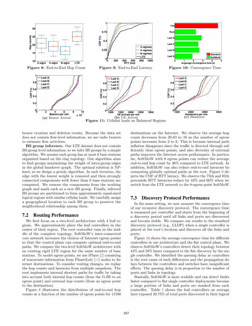
gions. We approximately place the leaf controllers in thecenter of their region. The root controller runs in the mid-dle of the complete topology. SoftMoW’s inter-connectedcore network increases the choices of Internet egress pointsso that the control plane can compute optimal end-to-endpaths. We compare the two-level SoftMoW architecture withan existing rigid LTE region for the same number of basestations. To model egress points, we use iPlane [2] consistingof traceroute information from PlanetLab [10] nodes to In-ternet destinations. To consider routing changes, we replaythe hop counts and latencies from multiple snapshots. Theroot implements internal shortest paths for traffic by takinginto account both internal hop counts (from the G-BS to anegress point) and external hop counts (from an egress pointto the destination).
Figure 8 illustrates the distribution of end-to-end hopcounts as a function of the number of egress points for 11590
destinations on the Internet. We observe the average hopcount decreases from 20.83 to 16 as the number of egresspoints increases from 2 to 8. This is because internal pathinflation disappears since the traffic is directed through suf-ficiently close egress points, and also diversity of externalpaths improves the Internet access performance. In particu-lar, SoftMoW with 8 egress points can reduce the averageend-to-end hop count by 36% compared to LTE network. Inaddition, SoftMoW can also reduce end-to-end latencies bycomputing globally optimal paths at the root. Figure 9 de-picts the CDF of RTT latency. We observe the 75th and 85thpercentile RTT latencies reduce by 43% and 60% when weswitch from the LTE network to the 8-egress point SoftMoW.
7.3 Discovery Protocol PerformanceIn the same setting, we now measure the convergence time
of our recursive discovery protocol. The convergence timeis measured per controller and starts from the beginning ofa discovery period until all links and ports are discoveredand become stable. We compare our results to the standarddiscovery protocol (e.g., LLDP) when a single controller isplaced at the root’s location and discovers all the links andports.
Figure 10 shows the average convergence time for differentcontrollers in our architecture and the flat control plane. Weobserve SoftMoW’s controllers detect their topology between44% and 58% faster compared to the flat discovery by the sin-gle controller. We identified the queuing delay at controllersis the root cause of such differences and the propagation de-lays between the controllers and switches have insignificanteffects. The queuing delay is in proportion to the number ofports and links in topology.
Basically, SoftMoW is more scalable and can detect faultsfaster compared to flat single controller deployments becausea large portion of links and ports are masked from eachcontroller. Table 1 shows the leaf controllers on averagehave exposed 20.75% of total ports discovered in their logical
SW Ports Links Ports Ports (%)Leaf A 55 218 80 58 26Leaf C 79 250 99 52 20Leaf B 68 213 87 39 18Leaf D 98 416 167 81 19Root 4 230 115 - -
0 12 24 36 480
3
6
9
12 x 105
Time (h)
Inte
r−re
gion
han
dove
rs (#
)
4GS4GS,Opt8GS8GS,Opt
Figure 12: Handover Optimization
region to the root controller. Also, 73% of total links arehidden at the root level.
7.4 Handover OptimizationWe characterize the cellular load on the leaf controllers
and the effectiveness of inter region handover optimizationthrough network measurement and simulation. We simulatea SoftMoW with two levels. In the first level, we define fourand eight roughly equal-sized logical regions, each assignedto a leaf controller. In the second level, the root controllermanages the abstract topology.
Cellular loads. Each leaf controller should handle threetypes of cellular events in addition to exposing logical devicesto the root: bearer arrival, UE arrival, handover request. Inpractice, each type of cellular event can triggers multiplerounds of message passing between the controller and thelogical data plane. Figure 11a shows the CDF of bearerarrivals. We observe each leaf controller handles as high as105 bearer arrivals per minute. We use the bearer arrivals asthe estimate of the number of packet-in messages received bythe leaf controllers. Figure 11b shows leaf controllers receiveand process between 1000 and 3000 attachment requests fromUEs connecting to a base station in their region, which aretriggered when users turn on their device. Figure 11c depictsthe aggregate intra region and inter region handover requestsprocessed by leaf controllers that varies between 1000 and4000 per minute.
Optimization results. Periodically, the root refines theabstract sub-regions exposed from the leaf controllers basedon its global handover graph. It strives to reduce the loadof inter region handovers, which also improves the handoverperformance. In the optimization, we avoid drastically un-balancing the three cellular loads on each leaf controllers.Figure 12 shows the number of inter region handovers handledby the root over 48 hours for 8-region and 4-region settings.We observe the number of handover requests increases (i)in peak hours and (ii) by doubling the number of logicalregions. The root runs the reconfiguration algorithm every 3hours by collecting local handover graphs. We assume eachGS (i.e., leaf controllers) should not handle more (less) than
30% of their maximum (minimum) initial cellular loads perminute. Given these constraints, Figure 12 depicts the rootcan reduce the load of inter region handovers by 38.08% to44.61% using our iterative greedy reconfiguration algorithm.
8. RELATED WORKScalable control planes. Maestro [8] utilizes parallelism
to achieve high scalability on multi-core machines. SoftMoWcan benefit from the proposed techniques to make logical andphysical rule installations faster at each node. HyperFlow [22]and Onix [17] are multi-controller designs without any explicithierarchical structure. Kandoo [14] improves HypeFlow byleveraging a two-level controller. Unlike SoftMoW, Kandoocannot be extended to more than two levels and can runspecific applications such as elephant flow detection. Incontrast to SoftMoW, these systems do not offer sufficientscalability to support continent-wide global applications.
Scalable data planes. To scale the data plane, Soft-MoW, PNNI [11], XBar [19] hierarchically abstract a givennetwork as logical entities. To control their specific targetnetwork and satisfy requirements, each of them offers differ-ent abstractions. PNNI’s abstractions is designed for ATMnetworks. SoftMoW is the first complete recursive and recon-figurable architecture with richer abstractions suitable forcellular WAN operators. Unlike XBar and PNNI, SoftMoWbuilds virtual fabrics for its G-switches to enable network-wide optimization such as routing. In addition, SoftMoWruns a novel recursive label swapping mechanism to minimizethe bandwidth overhead and data plane states.
Inter-DC control plane. Control plane architectures fordata center WANs such as B4 [16] and SWAN [15] are specificto inter-DC traffic engineering. Inter-DC WAN topologieshave several order of magnitudes fewer nodes and edgescompared to the cellular WAN topologies [9]. SoftMoW’srecursive and reconfigurable abstraction scales the networkmuch better.
Cellular network control plane. Recently, researchershave also proposed flexible control plane architectures forcellular networks. SoftRAN [13] is a design specific to radioaccess networks. SoftRAN handles intelligent resource blockallocation to optimize utilities. SoftCell [23] focuses on pro-viding operators with fine-grained policies and compressesdata plane rules. In contrast to prior work, SoftMoW handlesinter-connected cellular core networks.
9. CONCLUSION AND FUTURE WORKCellular wide area networks have become an integral part
of our society. However, they are remarkably inflexible andinefficient. This is exacerbated by the continued exponentialgrowth of mobile data. To address this important problem,in this paper, we present SoftMoW, a scalable architecturethat is based on on effective recursive and reconfigurableabstractions for both control plane and data plane. We de-signed a recursive link discovery protocol and virtual fabricsto allow automatic topology construction and support globalresource management. SoftMoW optimizes network-wideobjectives such as inter-region handover, path implementa-tion, and routing. SoftMoW achieves these goals using novelalgorithms benefiting from our scalable abstractions. Ourevaluation results show that SoftMoW is very efficient andscalable. For future work, we would like to deploy SoftMoWin a large testbed.
388
AcknowledgmentsWe would like to thank the anonymous reviewers for provid-ing valuable feedback on our work and Gordon Wilfong atBell Labs for helpful discussions on BGP. This research wassupported in part by the National Science Foundation undergrants CNS-1039657 and CNS-1345226.
[3] LTE design and deployment. http://goo.gl/DMKymH.
[4] Managing the signaling storm. http://goo.gl/lkTyb1.
[5] Zookeeper: Wait-free coordination for internet-scalesystems. In Proc. USENIX ATC, 2010.
[6] P. Berde, M. Gerola, J. Hart, Y. Higuchi,M. Kobayashi, T. Koide, B. Lantz, B. O’Connor,P. Radoslavov, W. Snow, et al. ONOS: towards anopen, distributed SDN OS. In Proc. workshop on Hottopics in software defined networking (HotSDN), 2014.
[7] M. Caesar, D. Caldwell, N. Feamster, J. Rexford,A. Shaikh, and J. van der Merwe. Design andimplementation of a routing control platform. In Proc.USENIX NSDI, 2005.
[8] Z. Cai and et al. The preliminary design andimplementation of the Maestro network controlplatform, 2008.
[9] Y. Chen, S. Jain, V. K. Adhikari, Z.-L. Zhang, andK. Xu. A first look at inter-data center trafficcharacteristics via yahoo! datasets. In Proc. IEEEINFOCOM, 2011.
[10] B. Chun, D. Culler, T. Roscoe, A. Bavier, L. Peterson,M. Wawrzoniak, and M. Bowman. Planetlab: anoverlay testbed for broad-coverage services. In ACMComputer Communication Review, 2003.
[11] T. A. Forum, M. Ahmed, and J. H. Rus. Privatenetwork-network interface specification version 1.0(pnni 1.0), 1996.
[12] A. Greenberg, J. R. Hamilton, N. Jain, S. Kandula,C. Kim, P. Lahiri, D. A. Maltz, P. Patel, andS. Sengupta. VL2: A scalable and flexible data centernetwork.
[13] A. Gudipati, D. Perry, L. E. Li, and S. Katti. SoftRAN:Software defined radio access network. In Proc.workshop on Hot topics in software defined networking(HotSDN), 2013.
[14] S. Hassas Yeganeh and Y. Ganjali. Kandoo: Aframework for efficient and scalable offloading ofcontrol applications. In Proc. workshop on Hot topicsin software defined networking (HotSDN), 2012.
[15] C.-Y. Hong, S. Kandula, R. Mahajan, M. Zhang,V. Gill, M. Nanduri, and R. Wattenhofer. Achievinghigh utilization with software-driven WAN. In Proc.ACM SIGCOMM, 2013.
[16] S. Jain, A. Kumar, S. Mandal, J. Ong, L. Poutievski,A. Singh, S. Venkata, J. Wanderer, J. Zhou, M. Zhu,et al. B4: Experience with a globally-deployed softwaredefined WAN. In Proceedings of the ACM SIGCOMM,2013.
[17] T. Koponen, M. Casado, N. Gude, J. Stribling,L. Poutievski, M. Zhu, R. Ramanathan, Y. Iwata,H. Inoue, T. Hama, et al. Onix: A distributed controlplatform for large-scale production networks. In Proc.USENIX OSDI, 2010.
[18] B. Lantz, B. Heller, and N. McKeown. A network in alaptop: rapid prototyping for software-defined networks.In Proc. workshop on Hot topics in software definednetworking (HotSDN), 2010.
[19] J. McCauley, A. Panda, M. Casado, T. Koponen, andS. Shenker. Extending SDN to large-scale networks,2013.
[20] R. Niranjan Mysore, A. Pamboris, N. Farrington,N. Huang, P. Miri, S. Radhakrishnan, V. Subramanya,and A. Vahdat. PortLand: A scalable fault-tolerantlayer 2 data center network fabric. In Proc. ACMSIGCOMM, 2009.
[21] N. Spring, R. Mahajan, and D. Wetherall. MeasuringISP topologies with Rocketfuel. In ACM ComputerCommunication Review, 2002.
[22] Tootoonchian, Amin and Ganjali, Yashar. Hyperflow:A distributed control plane for OpenFlow. In Proc.INM/WREN, 2010.
[23] Xin Jin and Li Erran Li and Laurent Vanbever andJennifer Rexford. SoftCell: Scalable and flexible cellularcore network architecture. In Proc. ACM CoNEXT,2013.
[24] K. Zarifis, T. Flach, S. Nori, D. Choffnes, R. Govindan,E. Katz-Bassett, M. Mao, and M. Welsh. Diagnosingpath inflation of mobile client traffic. In Proc.International Conference on Passive and ActiveNetwork Measurement (PAM), 2014.
[25] J. C. Zuniga, C. J. Bernardos, A. de la Oliva, T. Melia,R. Costa, and A. Reznik. Distributed mobilitymanagement: A standards landscape. CommunicationsMagazine, IEEE, 2013.