25
SoftView ® LITE Operation Manual

SoftView® LITEOperation Manual


3
TABLE OF CONTENTS
Overview 4
Product Features 5
Installation & Startup 7
Quick Start Guide 19
Communications Primer 22

4
The Mustang Sampling SoftView LITE communications software is provided by Mustang Sampling to its
customers. The software is provided without fee and therefore requires no registration.
SoftView LITE provides the user with a local or remote interface to the Mustang Sampling instrument.
The software is Windows-based and operates on a Windows XP, Windows 7, Windows 8 or Windows
10 PC platform.
Users unfamiliar with computer to instrument digital communications concepts and procedures
are encouraged to review the Communications Primer section at the end of this manual to better
understand the concepts and instructions discussed here.
This software is specifically designed to provide the user with an easy-to-use interface to the “smart”
Mustang Sampling product. The software operates as a Modbus “master” on a communications
network. The SoftView LITE software supports both a demand poll and auto-poll interface to the
instrument.
The SoftView LITE software saves the acquired measurement data in a history log file allowing the user
to monitor measurement history and to review the performance history of the instrument. The software
also supports features which can allow the user to configure the instrument.
The SoftView® LITE Software consists of two major components or modules.
1. SoftView LITE Client (the User GUI interface)
2. SoftView LITE SCADA Gateway Executive (SGX) Server
SoftView® LITE SOFTWARE OVERVIEW

5
The SoftView LITE software provides the user with a number of features including the following major features:
1. Simple Intuitive User Interface - An important SoftView LITE design priority was to provide the user with an interface which is simple, intuitive and easy to use. As you will see in the visualization discussion below, this has been achieved for the day-to-day software user.
2. Applications (APPs) - The information required by SoftView LITE to interface to an instrument is contained in an APP file for the instrument. So configuring SoftView LITE to interface to a particular instrument is a simple two-step process. First, the user installs the appropriate APP for the desired instrument and second, he then defines the communications parameters required for the instrument interface.
3. Training Mode Configuration – SoftView LITE supports a training mode configuration. The software training mode when configured allows the user to easily become familiar with the user GUI software interface. The user can exercise the functionality in the software without having a physical connection to the instrument. The instrument communications is virtual or simulated. The user can become familiarity with the software by installing and polling the virtual instrument. Then, when ready, the user can easily switch the configuration to use the physical interface to the real instrument.
4. Instrument Configuration – The SoftView LITE instrument APP for interface to the instrument will usually contain “read only” measurement report data and “read/write” configuration parameter report data. So the SoftView LITE user can also read (poll) and re-configure key parameters in the instrument by editing and downloading configuration parameters to the instrument.
5. History Logging and Trending – The user can review a graphic trend of selected measurement values in the history data log.
The SoftView LITE user can:
1. Install an interface APP for the desired instrument, i.e. the “Focus APP”.
2. Define the communications link to the instrument. Communications options include serial or Ethernet network connections.
3. Select the “Focus Report”, i.e. the specific data desired from the instrument.
4. Poll on demand or auto-poll the focus report data from the instrument.
5. Tune or re-configure the instrument by editing and downloading configuration parameters to the instrument.
6. Save acquired data from the instrument in a history data log.
7. Review the latest acquired instrument data and alarm status.
8. Review a graphic trend of selected measurements in the history data log.
9. Export saved history log data to a CSV file for import into Excel.
SoftView® LITE FEATURES

6
10. Print history data log reports.
SoftView® instrument applications (APPs) are provided in the SoftView LITE software to support communications with the following Mustang Sampling instruments (focus instruments):
1. P53™ Sample Conditioning System
2. Pony® Heated Probe Enclosure with Mustang Heated Regulator (MHR™)
3. Mustang® NGL Sample Conditioning System (MNGL™)
4. Mustang® Heated Regulator
5. Mustang Intelligent Vaporizer Sample Conditioning System® Model 1 (MIV1)
6. Mustang Intelligent Vaporizer Sample Conditioning System® Model 2 (MIV2)
7. SS2000 Moisture Analyzer
8. MTC1
SoftView LITE supports the following communications media or links to the instrument:
1. Serial over a COMx RS232 port or RS485 with a converter.
2. Ethernet (TCP/IP)
Users interested in additional features should review the capabilities available in the SoftView Plus and SoftView LNG software from Mustang Sampling.

7
To install the software, click on the SoftView LITE setup….exe and follow the install wizard instructions.
After the software is installed, click on the SoftView LITE icon to open the software. The above progress window indicates software startup and initialization of the CST Mustang Sampling SCADA Gateway Server.
The Operations window is presented to the user when the Server initialization is complete.
SoftView® LITE INSTALLATION & STARTUP
INSTALLATION
STARTUP

8
The Operations window is the “home page” for the user for all instrument communications.
OPERATIONS WINDOW
9
The following Menu Functions related to user interface are available on all windows and are important to note:
Exit Menu Function – Close Software
The Exit menu function is used to close the SoftView® Lite software. This function should be used in order to insure that the SoftView LITE Client and Server are able to close all files appropriately before shutdown.
Zoom Menu Options – Change Window Size
The Zoom menu function can be used to adjust window size.
Help Menu Function – Help Documentation Access
PDF documentation related to SoftView LITE and the Mustang Sampling instruments can be accessed and reviewed online via the Help / Content Menu option if the Adobe reader AcroRd32.exe is installed on the user’s computer. The user can access this information by clicking on the Help Content option. The first time this is done, SoftView LITE attempts to locate the reader file and informs the user of success or failure. After the path to the file has been identified, the user is presented with a list of documentation which can be directly accessed.
SoftView LITE Window Tool Buttons for Navigation
The above buttons are used to access the Operations, Trend, Event, and Setup Windows, respectively in SoftView® LITE and to request a window refresh or to freeze auto refresh mode.
MENU FUNCTIONS
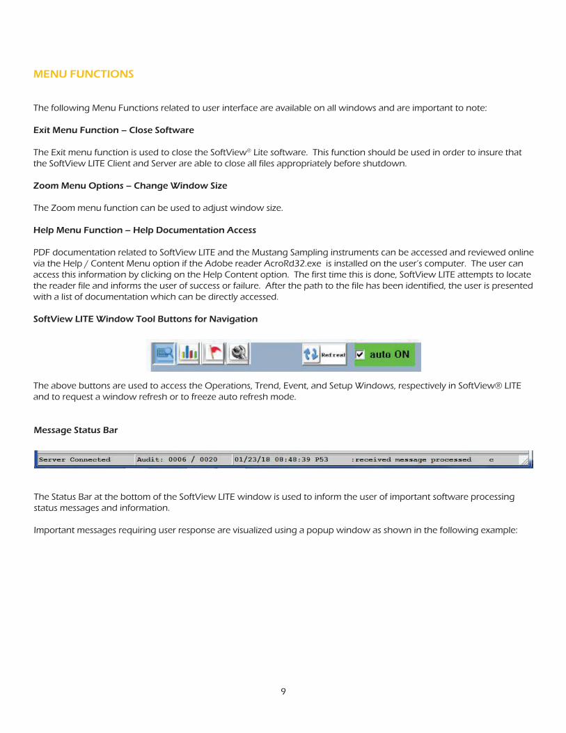
Message Status Bar
The Status Bar at the bottom of the SoftView LITE window is used to inform the user of important software processing status messages and information.
Important messages requiring user response are visualized using a popup window as shown in the following example:

10
The Operations window is used to communicate with the instrument and to review data acquired from the instrument.
Instrument Application Field
The Application field at the top identifies the currently installed instrument application or APP. The installed APP is called the “Focus APP.”
OPERATIONS WINDOW FEATURES
Click on the highlighted blue “Application” area to access a graphic picture of the focus instrument for review.
Instrument Report Field
Click on the down arrow in the Reports field application to view a list of defined reports for the current instrument or Focus APP.
The selected report is called the “Focus Report.” The report contains pre-defined measurement items or “Cells” which are displayed in the Instrument Data Field. Click on the down arrow in the Reports field application to view a list of defined reports and to change the Focus Report.
Instrument Data Field
Use the scroll bar in the Instrument Data field to scroll through the report measurement or cell values.

11
For read/write “configuration” reports containing configuration items, the user can click on the cell in the Instrument Data window to edit the current value for the cell item.
There are generally four types of reports which may be available to the user for an instrument.
1. Operations or Primary Measurement Report The instrument primary measurement data is contained in this report. This report is a Read Only report polled from the instrument on demand via the Read Instrument button or automatically via the AUto Poll feature. The data in this report when polled is captured in a history log.
2. Expanded Measurement Report This is a Read Only expanded report containing additional measurement data in addition to the primary measurement data. This report is polled from the instrument via the Read Instrument button. The data in this report when polled is captured in a history log.
3. Diagnostics Reports This report is a Read Only report containing “diagnostic” parameters which are useful in monitoring instrument performance and determining if instrument maintenance is required.
4. Configuration Reports These reports are Read and Write reports containing instrument configuration parameters. The user can poll these parameters, tweak or tune them as desired, then download the new settings to the instrument.

12
The Read Instrument and Update Instrument buttons are used to demand poll the Focus Report data for the Focus instrument. Live measurement report data when polled from the instrument is saved in a history log. Acquired data for the Focus Report is displayed in the Instrument Data field. If the connection to the instrument is a serial COM connection using a USB port, the user should plug in the USB cable prior to opening SoftView® LITE so the COM port exists for the software.
The “real time” graphic trend visualization at the bottom of the window allows the user to review graphically a trend of the latest 60 measurement values for the user selected measurement. Click on the field down arrow to the left of the trend to select the desired measurement.
To configure SoftView LITE to communicate for the first time with an instrument, the user must access the Setup Window discussed below to install the instrument APP and to define or adjust, as necessary, the communications parameters needed for the instrument communications session.
REVIEWING COLLECTED INSTRUMENT DATA

13
The Actions button on the Operations Window allows the user to request specific processing by SoftView LITE. Key actions available are:
1. Initialize Comm - to initialize the assigned COMM ports
2. Stop Active Comm - to terminate currently active communications
3. Print Report - to print the current Focus Report data
4. Export Report - to capture the current Focus Report data to a digital file
5. Print History Actions - to print the current saved history data for the Focus Report
6. Export History - to capture the current saved history dat for the Focus Report to a digital file
7. Clear History - to flush all saved history for the current Focus Report
8. Synchronize History - for instruments with embedded history log capability, to synchronize the software with the latest history acquired from the instrument
OPERATIONS WINDOW ACTIONS

14
SETUP WINDOW
Click on the Wrench navigation button to access the Setup window. This window is used to install the desired instrument APP and to define the communications profile for the SoftView® Lite interface to the instrument.
The Instrument field identifies the currently selected “Focus APP” or instrument. Click on the down arrow to select a desired Focus APP or instrument followed by a click on the Apply button to install the APP.
The Report field identifies the currently selected “Focus Report.” The focus APP will usually contain one or more read only measurement reports and one or more read/write reports containing instrument configuration parameters. Click on the Report down arrow to select the desired report for the Focus APP or instrument followed by a click on the Apply button.
SoftView LITE, when initially installed, is pre-configured with the P53 instrument APP and for training mode (note the Serial 4 assignment). This mode allows the user to do demand and auto-polling of the first focus report from the instrument, e.g. the P53-OP focus report from the P53 virtual device, without a physical connection to the instrument.
Communications is virtual or simulated. The user can therefore use the Training Mode to gain familiarity with the software.
The Serial 4, Serial 5, Serial 6, and Serial 7 fields (lower right) are used to designate the computer’s COM serial ports to be used for serial communications. If the “Train” option is selected, then the polling function for the instrument assigned to that Serial option will operate in Training Mode using virtual communications.
Note the communications settings fields for the instrument:
Active Yes
Modbus Address The Modbus Address for the instrument
Interface Serial link option assignment, e.g. Serial 4
Address IP address if interface is via an Ethernet link

15
IP Port IP Port if interface is via an Ethernet link
Serial 4 Serial COM port to use for Serial 4 APPs
Serial 5 Serial COM port to use for Serial 5 APPs
Serial 6 Serial COM port to use for Serial 6 APPs
Serial 7 Serial COM port to use for Serial 7 APPs
Serial Config COMM parameters Baud Rate, Parity, etc.
After any user change or edit, the Apply button is used to install the user changes made to the fields on the Setup window.
SoftView® Lite can only communicate with an instrument to acquire the focus report data if:
1. The instrument APP has been installed as the “Focus APP.”
2. The communications parameters for the instrument are set correctly to match those in the instrument and the link settings matches the customer’s installation.
3. The COM port assigned to the Focus APP is recognized, i.e. exists. If a USB port is to be used for the serial COM port, the user should therefore plug in the USB cable prior to opening SoftView LITE or use the “Connect to Port” action defined below after connecting the cable.
Once the settings are defined for the installed instrument, SoftView LITE retains these settings so they do not have to be repeated unless the instrument APP is re-installed.

16
SETUP WINDOW ACTIONS
The Action button on the Setup Window allows the user to request specific processing by SoftView LITE. Key Actions available are:
1. Connect to Port – used to establish software connection to the computer COM port.
2. Disconnect Port – instructs the software to release the port so other software can use it.
3. Initialize Comm – Initializes the assigned COMM ports.

17
TREND WINDOW
Click on the Graph navigation button to access the Trend Window. Data acquired from Measurement Reports via the Operations window is saved in history or data log files.
The Trend Window allows the user to review graphically captured history for the current Focus instrument and Focus report. The user can page through the data using the “Latest,” “Next,” and “Previous” buttons and can select a measurement of interest for review. Placing the cursor on the trend will display the X and Y coordinates for the trend.

18
SERVER EVENTS WINDOW
The Event Window is accessed via the Flag navigation button.
The CST SCADA Gateway Executive (SGX) XML Server is the communications front-end for the SoftView LITE software. The Server Events window allows the user to review the latest audit trail of server events. This is particularly helpful in diagnosing communications problems with the instrument.

19
QUICK START GUIDE - SoftView® LITE
SoftView LITE, when initially installed, is pre-configured for training mode. This mode allows the user to exercise basic software functionality without a physical connection to the instrument. The communication is virtual or simulated. The user should use this configuration to gain familiarity with the software.
1. Install the SoftView LITE software.
2. Use the default Training Mode and the above Visualization section documentation to become familiar with the user interface.
3. Proceed with the next step to configure SoftView LITE for field operation and interface to the field instruments.
1. Attach the USB to Serial Converter if needed.
2. Identify the computer COMx port to be used.
3. Access the Setup Window.
4. Click on the Serial 4 field down arrow and select the COMx port.
5. Click on the Apply button to establish the software to serial port connection
1. Access the Setup Window.
2. Click on the Application field down arrow to review the list of instrument APPs.
3. Select the desired instrument APP.
4. Click on the Apply button to install the APP.
STEP 1 - BECOME FAMILIAR WITH THE USER INTERFACE
STEP 2 - ESTABLISH THE SERIAL PORT CONNECTION
STEP 3 - INSTALLING THE INSTRUMENT APP

20
1. Complete Steps 1, 2 and 3 above.
2. Plug the instrument cable into the USB converter or the Ethernet connection to establish the physical connection between the computer and the instrument.
3. Access the Operations window.
4. Select the desired instrument report as the Focus Report.
5. Click on the Read Instrument button to poll the instrument.
6. If errors are reported, return to the Setup Window and check the instrument connection and communication settings.
7. The COM port assigned to the Focus APP must be recognized, i.e. exist. If a USB port is to be used for the serial COM port, the user should plug in the USB converter prior to opening SoftView LITE or use the “Connect to Port” action after connecting the cable.
STEP 5 - COMMUNICATING WITH THE INSTRUMENT
1. Access the Setup Window.
2. Use the Modbus Address field to define the Modbus address of the instrument.
3. Use the Interface field to set the desired serial or Ethernet link option.
4. If a Serial N Interface option is chosen, use the Serial N Port field to define the COMx serial port on the computer to be used for the communication link.
5. If the Ethernet option is chosen, enter the IP address in the Address field and the Ethernet port number in the IP Port field.
6. Use the Serial Config field to select the appropriate baud rate, parity, #data bits, and #stop bits for the communications link.
7. Click on the Apply button to install the new settings.
SoftView® Lite supports a serial or an Ethernet (TCP/IP) connection to the instrument. Once the link definition is defined, it will remain in effect, i.e. the user does not have to re-define it, unless the link parameters change or unless the user has installed a different “APP” in the instrument slot.
STEP 4 - DEFINING THE INSTRUMENT COMMUNICATIONS PARAMETERS

21
1. Verify valid communications via the above steps.
2. Access Operations window.
3. Edit if desired the auto-poll frequency.
4. Click on the Auto-Poll check box to enable auto-poll.
5. When ready, click on the Auto-Poll check box to turn off the aut-poll.
1. Use the Auto-Poll feature to collect history data for the Focus Report.
2. You will see a real time trend of the selected measurement as data is collected.
3. Click on the Trend Measurement field down arrow to select the desired measurement.
4. You will see a real time trend of selected measurement as data is collected.
5. You can also export the history data to a CSV file and import into Excel if desired.
1. Verify valid communications via the above steps.
2. Access the Operations window.
3. Select the desired Configuration Report as the Focus report.
4. Click on the Read Instrument button to poll the current configuration settings from the instrument WARNING: This is a required step to ensure that SoftView LITE contains the current instrument setting.
5. Review the current settings.
6. Click on each setting to be changed and edit the value as desired.
7. When editing is complete, click on the Update Instrument button to write the Configuration Report with the new settings to the instrument.
STEP 6 - AUTO-POLLING THE INSTRUMENT
STEP 7 - SELECTING A MEASUREMENT FOR GRAPHIC TRENDING
STEP 8 - CONFIGURING INSTRUMENT PARAMETERS

22
1. The serial COMx port, e.g. COM1, or the Ethernet connection, serves as the communications media connection.
2. SoftView LITE can communicate with many instruments in the field so the software must know the instrument “address” of the desired instrument. This is the instrument Modbus address and, if Ethernet, also know the IP address and Ethernet port number. The user must pre-define these in SoftView LITE.
3. Softview Lite establishes the session with the requested instrument when the user wants to retrieve data from the instrument, e.g. he clicks on the Read Instrument or Update Instrument button or requests that an “Action” be executed.
4. When the instrument answers, SoftView LITE automatically recognizes that the link is “established.”
5. SoftView LITE will now communicate with the instrument if and only if:
a. They speak the same language, i.e. Gould Modbus RTU (GMR) protocol.
SOFTVIEW LITE TO INSTRUMENT COMMUNICATIONS SESSION
The following information will help users with little or no experience in remote data communications to instruments to understand some key communicatiosn related concepts.
Communicating remotely with an instrument requires that the user’s PC or laptop, with SoftView LITE software, establish a connection, i.e. a communications link to the local or remote instrument. A good analogy is to consider a phone call. Let’s assume that Person A wishes to talk to Person B.
Person A to Person B Communications Session
1. The telephone will serve as the communications media.
2. Person A must specify the “address,” i.e. phone number for Person B so the phone media knows which remote phone or node to connect to the Person A phone.
3. Person A enters the phone number and waits for B to answer.
4. When B answers and sends a “hello” message to A, the link can be considered “established” and communications can begin.
5. Person A can now communicate with B if and only if:
a. They speak the same language or “protocol,” e.g. English
b. They speak using an understandable voice volume and speech rate (baud rate)
6. A asks B a question, i.e. sends a “command”, understands it, and responds with the desired information, i.e. sends a “response” to A.
7. A is satisfied, says goodbye and hangs up the phone, i.e. issues a disconnect message to terminate the connection and close the communications sessions.
SOFTVIEW® LITE COMMUNICATIONS PRIMER

23
b. They speak using the same data rate (SoftView LITE must use the baud rage, e.g. 9600,N,8,1 which is configured in the instrument.
6. Softview Lite asks the instrument a question, i.e. sends a message, i.e. command, using Modbus language soliciting information from the instrument.
7. The instrument receives the command, understands it, and responds with the desired information using the Modbus protocol or language.
8. SoftView LITE receives the information, processes it, is satisfied and disconnects the link if the user does not request additional data, thus terminating the communications session.
Before SoftView LITE can communicate with an instrument, the user must define the above information for the instrument. This information is entered using the Setup window discussed below. This information only needs to be entered once for a particular installed instrument as SoftView LITE retains the information.

24
The SoftView® software products and associated documentation are the property of Mustang Sampling, LLC. The SoftView® application uses the SCADA Gateway Executive (SGX) software from Cline SofTechnology (CST) which is protected by copyright laws. All electronic duplication or reverse engineering or photocopy duplication of associated documentation without permission from Mustang Sampling, LLC and CST is expressly prohibited.

About Mustang SamplingMustang Sampling, LLC is the innovator of Analytically Accurate® solutions within sample conditioning systems. We provide custom solutions of products and services globally to the Natural Gas, Natural Gas Liquids (NGL), and Liquefied Natural Gas (LNG) industries. Mustang Sampling continues to pioneer integrated control systems, allowing our customers to maintain phase stability from sample extraction at the pipeline through sample analysis. Our products are continuously improved and subjected to the highest quality standards which provides our customers with the best sample conditioning solutions.
Mustang Sampling, LLC 43 Ritmore GlenRavenswood, WV 26164P: +1 304 273 5357F: +1 304 273 2531 [email protected]
Copyright © 2018 Mustang Sampling. All rights reserved.Mustang Sampling®, Mustang®, Pony®, Mustang Intelligent Vaporizer Sampling System®, Analytically Accurate® and SoftView® are registered trademarks of Mustang Sampling, LLC.
No part of this publication may be reproduced in any material form without the written permission of Mustang Sampling, LLC and Cline SofTechnology (CST).
MS-IOMSVLITE.v2-EN-P February 2018Supersedes: SoftView LITE Operations Manual-H901
TECHNOLOGYAnalytically Accurate®


