114
Software Defined Networks (SDN) and Network Functions Virtualisation (NFV) Understanding the concepts and technical foundations Bruno Chatras December 2018

1
Software Defined Networks (SDN) and Network Functions Virtualisation (NFV)
Understanding the concepts and technical foundations
Bruno Chatras
December 2018
2
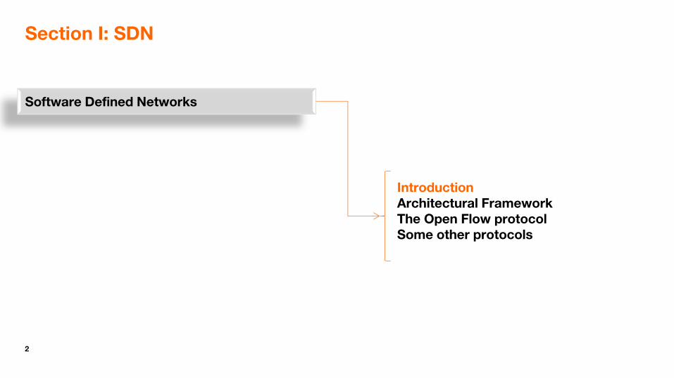
Section I: SDN
Software Defined Networks
Introduction Architectural Framework The Open Flow protocol Some other protocols

3
Some definitions
ITU-T:
A set of techniques that enables to directly program, orchestrate, control and manage network resources, which facilitates the design, delivery and operation of network services in a dynamic and scalable manner.
From Y.3300
IETF
The set of techniques used to facilitate the design, the delivery and the operation of network services in a deterministic, dynamic, and scalable manner.
From RFC 7149
A programmable networks approach that supports the separation of control and forwarding planes via standardized interfaces.
From RFC 7426
Open Networking Foundation (ONF):
An emerging architecture that decouples the network control and forwarding functions enabling the network control to become directly programmable and the underlying infrastructure to be abstracted for applications and network services.

4
WAN
Without SDN…in the worst case
Ordering /provisioning of networks is mostly done manually
Vendor X
Vendor Y
Vendor Y
Vendor Z
Wants to connect
two sites to an
Enterprise VPN
and to the Internet
Field team
BSS OSS
Resource management team
Ordering team
Site A
Site B

5
WAN
Without SDN…in the worst case
ordering /provisioning of networks is mostly done manually
Vendor X
Vendor Y
Vendor Y
Vendor Z
Wants to connect
two sites to an
Enterprise VPN
Field team
BSS OSS
Resource management team
Ordering team
Site A
Provisioning team
Site B

6
Operator’s expectations
Become more independent from big network equipment manufacturers (roadmaps, pricing, etc.)
Seeking for more competition on controlling elements
Faster (and cheaper) service development and deployment
Develop and deploy advanced features on a limited number of controlling elements
Greater scalability
Control plane and data plane functions have different scaling requirements

7
WAN
With SDN (and NFV) … in the ideal case
ordering /provisioning of networks is automated
Vendor X
Vendor Y
Vendor Y
Vendor Z
Wants to connect
two sites to an
Enterprise VPN
Client
Site A
Site B
SDN App
SDN Ctrl
SDN Northbound Interface

8
Agenda
Software Defined Networks
Introduction Architectural Framework The Open Flow protocol Some other protocols
9
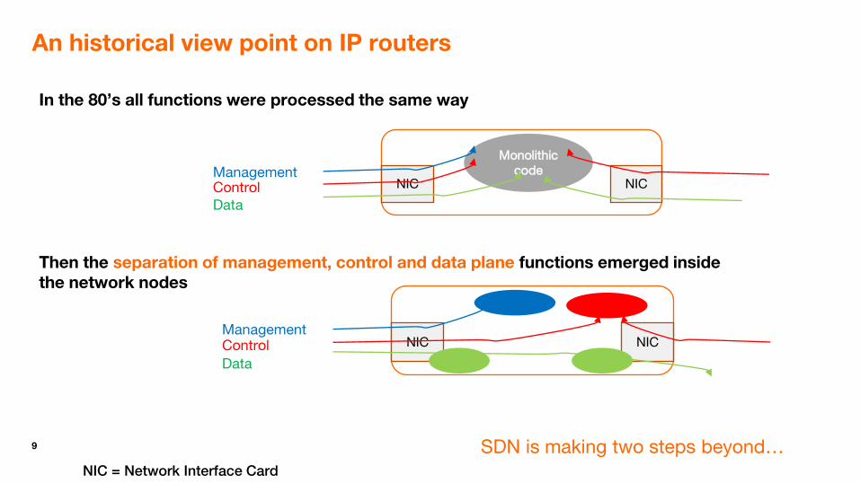
An historical view point on IP routers
In the 80’s all functions were processed the same way
Then the separation of management, control and data plane functions emerged inside the network nodes
NIC
Monolithic code
NIC Management Control Data
NIC NIC Management Control
Data
SDN is making two steps beyond… NIC = Network Interface Card

10
SDN is making two steps beyond
Interfaces between planes and towards applications become open interfaces
One single logical control plane instance can control multiple data plane instances: network-wide approach
and is applicable to all “network” layers: 1, 2 and 3
11
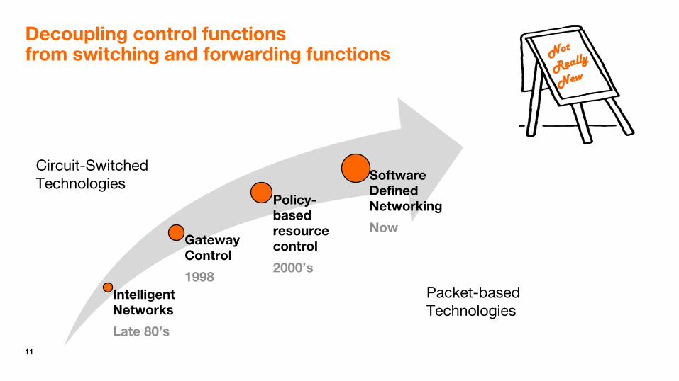
Decoupling control functions from switching and forwarding functions
Intelligent Networks
Late 80’s
Gateway Control
1998
Policy-based resource control
2000’s
Software Defined Networking
Now
Circuit-Switched Technologies
Packet-based Technologies

12
Architectural foundations
Network programmability
Applications are provided with an abstract view of the network and can control its behaviour through a set of Application Programming Interfaces (APIs).
Decoupling control plane from forwarding plane functions.
A controller is provided with an abstract view of the forwarding process and instructs network devices on how to forward data.
Monolithic Equipment
SDN Application Plane
SDN Control Plane
SDN Forwarding Plane
Northbound Open Interface
Southbound Open Interface

13
The global network view
A Vendor X
B Vendor Y
D Vendor Z
C Vendor Y
SDN Control Plane
SDN App#1
SDN App#2
SDN App#3
SDN/ App#4
Northbound Interface (s)
Southbound Interface (s)

14
Centralized vs. Distributed Control
A single logically centralized controller per SDN domain
but usually implemented in a distributed manner (i.e. multiple instances) for enabling high-availability.
The architecture can distributed at the logical level as well as many end-to-end use cases will involve multiple SDN domains.
− East-West interfaces are typically implemented through gateway protocols such as BGP [RFC4271] or other protocols such as the Path Computation Element (PCE) Communication Protocol (PCEP) [RFC5440].
East-West interface

15
Key challenges
High availability
Involvement of an external controller in decision-making must not compromise network services availability (single point of failure to be avoided).
− Redundancy and failover capabilities are important
High performance
Involvement of an external controller in decision-making must not affect packet forwarding performance (e.g., transit delays must not be impacted).
− Controller scalability and efficient congestion control are important
Secure the controller
If the SDN Controllers is compromised, the whole network is compromised.
− If the SDN Controller goes down (for example, because of a DDoS attack), so goes the network.

16
High Availability
Different High Availability (HA) and redundancy scheme are possible (active-active, active-passive, N+1, etc.)
Switches are typically connected to multiple controller instances.
State Synchronization can be achieved through inter-instances communication or by externalizing state in a shared HA distributed data base.
State Synchronization
Multi-instance SDN controller

17
Multi-domain SDN
SDN will be deployed in large-scale networks, likely to be divided into multiple connected SDN domains, for better scalability and security and/or administrative purposes.
Inter-SDN controller communication is required.
Vertical (hierarchical) approach
Horizontal (peer to peer) approach, with east-west interfaces

18
Northbound interfaces on SDN controllers
Multiple solutions as well!
Mostly in the form of REST APIs
Declarative (Intent-based) vs. Prescriptive

19
Southbound interfaces on SDN controllers
Southbound interfaces may take multiple forms depending on whether the connected planes reside on the same (physical or virtual) device.
When they do not reside on the same device, a plurality of protocol options exist:
OpenFlow
ForCES
NETCONF
RESTCONF
PCE
XMPP
OVSBD
PFCP
P4
POF
And a lot of proprietary variants and solutions

20
The high level software architecture of a general purpose SDN controller
Core Functionality
Southbound Abstraction Layer
Protocol specific drivers and plugins
Service Exposure Layer
REST APIs
Switch-specific protocols
SD
N C
on
tro
lle
r
Examples include OpenDayLight ONOS OpenContrail etc.
21
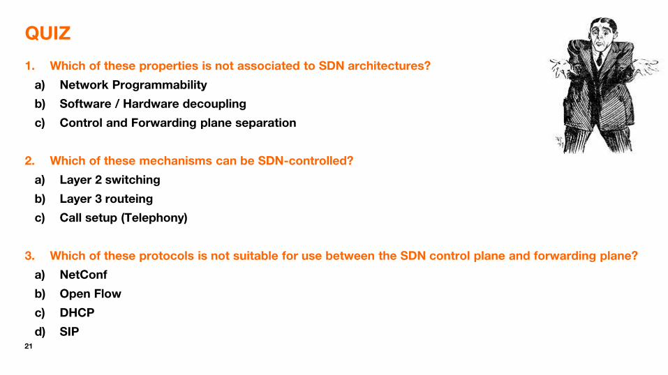
QUIZ
1. Which of these properties is not associated to SDN architectures?
a) Network Programmability
b) Software / Hardware decoupling
c) Control and Forwarding plane separation
2. Which of these mechanisms can be SDN-controlled?
a) Layer 2 switching
b) Layer 3 routeing
c) Call setup (Telephony)
3. Which of these protocols is not suitable for use between the SDN control plane and forwarding plane?
a) NetConf
b) Open Flow
c) DHCP
d) SIP

22
Agenda
Software Defined Networks
Introduction Architectural Framework The Open Flow protocol Some other protocols

23
OpenFlow switch protocol
The OpenFlow switch protocol provides access to the forwarding plane of a network switch or router.
It runs over TCP or TLS
OpenFlow is specified by the Open Networking Foundation (ONF)
Latest Version: 1.5.1 (2015)
Extensions published in 2017 for MPLS-TP and Optical Transport.
https://www.opennetworking.org/software-defined-standards/specifications/

24
Basic flow diagram
OF switch receives a packet (1)
If there are no rules about handling this packet
Forward packet to the controller (2)
Controller instructs the switch to output the packet and installs a rule for the packet flow (3)
OF Switch forwards the packet (4)
Subsequent packets for the same flow do not go through the controller.
Open Flow Controller
Open Flow Switch
Packet Processing
Packet In Packet Out
Rules
(1)
(2) (3)
(4)

25
Basic pipeline operation
The behavior of an OpenFlow Switch is modeled as a pipeline that consists of one or more flow tables.
If a flow entry is found in a table, the instruction set included in that flow entry is executed
The controller can add, update, and delete flow entries in flow tables, both proactively and reactively (in response to packets).
Pipeline processing instructions allow packets to be sent to subsequent tables for further processing, and allow information, in the form of metadata, to be communicated between tables.
Table
0 Table
1 Table
n Execute
Action Set
Packet in
Packet out
Typically forwarded to a physical port or a logical port (e.g. representing a tunnel endpoint).
Ingress Port
Output Port

26
Reactive vs Proactive interactions
First packet of flow triggers controller to insert flow entries
Efficient use of switch memory
Every flow incurs small additional flow setup time
If control connection lost, default behavior applied.
Controller pre-populates flow tables
Zero additional flow setup time
Loss of control connection does not disrupt traffic
Essentially requires aggregated (wildcard) rules
Reactive Proactive
An hybrid approach is possible as well – Default rules in case of control connection loss for reactive mode – Exception handling for proactive mode.

27
OpenFlow switch protocol
Simple binary protocol.
Specified as a C header file (.h)
3 types of messages
controller-to-switch
asynchronous
symmetric
enum ofp_type {
/* Immutable messages. */
OFPT_HELLO = 0, /* Symmetric message */
OFPT_ERROR = 1, /* Symmetric message */
OFPT_ECHO_REQUEST = 2, /* Symmetric message */
OFPT_ECHO_REPLY = 3, /* Symmetric message */
OFPT_EXPERIMENTER = 4, /* Symmetric message */
28
Key OpenFlow messages
Controller-to-switch
Packet-out: when the controller wants to send a packet out of the switch
Modify-flow-entry: when the controller wants to modify the a flow table
Switch-to-controller
Packet-In: Reports arrival of an incoming packet

29
Packet Processing decision logic
Packet In
Packet Out
Match in
table n?
Table-miss
flow entry
exists?
Goto-
Table n?
Group
action?
Output
action?
Switch
has egress
tables? Drop packet
Drop packet
Update counters
Execute instruction set:
• Update action set
• Update packet headers
• Update match set fields
• Update pipeline fields
Execute action set:
• Update packet headers
• Update match set fields
• Update pipeline fields
Yes
Yes
Yes
Yes Yes
Yes No
No
No
No
No
No
Egress processing

30
Flow Tables and Entries
• Write-Actions
• Go-To-Table
• Clear-Actions
• Apply-Actions
• Write-Metadata
• Stat-Trigger
Switch
Port
MAC
src
MAC
dst
Ether
type
VLAN
ID
VLAN
Priority
MPLS
Label
MPLS traffic class
Src
IP
Dst
IP
Protocol
No. ToS
Src
port
Dst
port
Meta
data
Match fields of OpenFlow 1.1
Flow entry Match Fields Counters Instructions Priority Timeout Cookies Flags
• Output (forward to port)
• Group
• Set-Queue
• Meter
• Push-Tag / Pop-Tag
• Set-Field
• Copy-Field
• Change-TTL
• Drop packet

31
OpenFlow table entries - examples
L2 Switching
*
Switch Port
MAC src
MAC dst
Eth type
VLAN ID
IP Src
IP Dst
IP Prot
TCP sport
TCP dport
Action
* 00:1f:.. * * * * * * * output port6
L3 Flow Switching
port3
Switch Port
MAC src
MAC dst
Eth type
VLAN ID
IP Src
IP Dst
IP Prot
TCP sport
TCP dport
Action
00:20.. 00:1f.. 0800 vlan1 1.2.3.4 5.6.7.8 4 17264 80 output port6
L4 Firewall
*
Switch Port
MAC src
MAC dst
Eth type
VLAN ID
IP Src
IP Dst
IP Prot
TCP sport
TCP dport
Action
* * * * * * * * 22 drop

32
OpenFlow table entries - examples
Packet Inspection
*
Switch Port
MAC src
MAC dst
Eth type
VLAN ID
IP Src
IP Dst
IP Prot
TCP sport
TCP dport
Action
* * * * * * 46 * * output
controller
NAPT
1
Switch Port
MAC src
MAC dst
Eth type
VLAN ID
IP Src
IP Dst
IP Prot
TCP sport
TCP dport
Action
* * * * 10.1.2.3 * * 22 *
Set Field (IP Src =139.100.1.1) Set Field (TCPsport = 20320) Output: Port2

33
OpenFlow table entries – example (VLAN)
port3
Switch Port
MAC src
MAC dst
Eth type
VLAN ID
IP Src
IP Dst
IP Prot
TCP sport
TCP dport
Action
* 00:1f:.. * * * * * * * output port6
+ push VLAN Tag
port5
Switch Port
MAC src
MAC dst
Eth type
VLAN ID
IP Src
IP Dst
IP Prot
TCP sport
TCP dport
Action
* 00:31:.. * vlan1 * * * * * output port3
+ pop
VLAN Tag

34
More fields (Version > 1.3)
New features
IPv6
SCTP
ARP
ICMP
…

35
Quiz
A. Which of these assertions are valid?
1. The OpenFlow protocol runs on UDP
2. The OpenFlow protocol enables configuring a switch to add a VLAN tag to packets coming from specific sources.
3. The OpenFlow protocol enables adding a flow entry in a flow table.
4. The OpenFlow protocol enables configuring a switch to so that all packets to a particular IP address are dropped if the bitrate going to this address exceeds a threshold.
5. A packet that does not match any flow entry is dropped.
B. Which of these packet fields cannot be handled by an OpenFlow controller
1. A Source IP address
2. A Destination MAC address
3. An HTTP URI
4. A VLAN tag
5. A DiffServ code point

36
Agenda
Software Defined Networks
Introduction Architectural Framework The Open Flow protocol Some other protocols

37
The Packet Forwarding Control Protocol (PFCP)
The Packet Forwarding Control Protocol (PFCP) protocol is used to control the user plane function.
PFCP is a 3GPP native protocol with TLV encoded messages over UDP/IP. See 3GPP TS 29.244
It borrows many concepts from OpenFlow.
In the context of 5G Core Networks, it used by the Service Management Function (SMF) to control User Plane Functions (UPF).
PFCP

38
The Packet Forwarding Control Protocol (PFCP)
The protocol enables controlling packet processing in the user plane function by establishing, modifying or deleting PFCP Session contexts and by provisioning (i.e. adding, modifying or deleting) rules for packet detection (PDR), forwarding (FAR), QoS enforcement (QER) and usage reporting (URR).
A PDR is similar to an entry in an OpenFlow flow table. FAR, QER and URR are equivalent to the instructions found in an OpenFlow flow table entry.
PDR
Packet In Packet Out
PDR
PDR
PDR
Sx session’s
PDR look up
(find
matching
PDR of the
Sx session
with highest
precedence)
...Apply Instructions set in the
matching PDR
FARs QERs URRsSx Session
look up
(find Sx
session with
a matching
PDR )

39
Programming Protocol-independent Packet Processors (P4)
Motivation
Openflow explicitly specifies the protocol header fields on which it operates.
New set of header fields are added in subsequent versions of the protocol and software and possible hardware updates have be performed on all controlled switches.
The Openflow approach is not sustainable as the number of fields to take into account will continue to increase due to multiple encapsulation methods appearing ((VXLAN, NVGRE, STT, etc.)
Programming Protocol-Independent Packet Processors
https://p4.org/
40
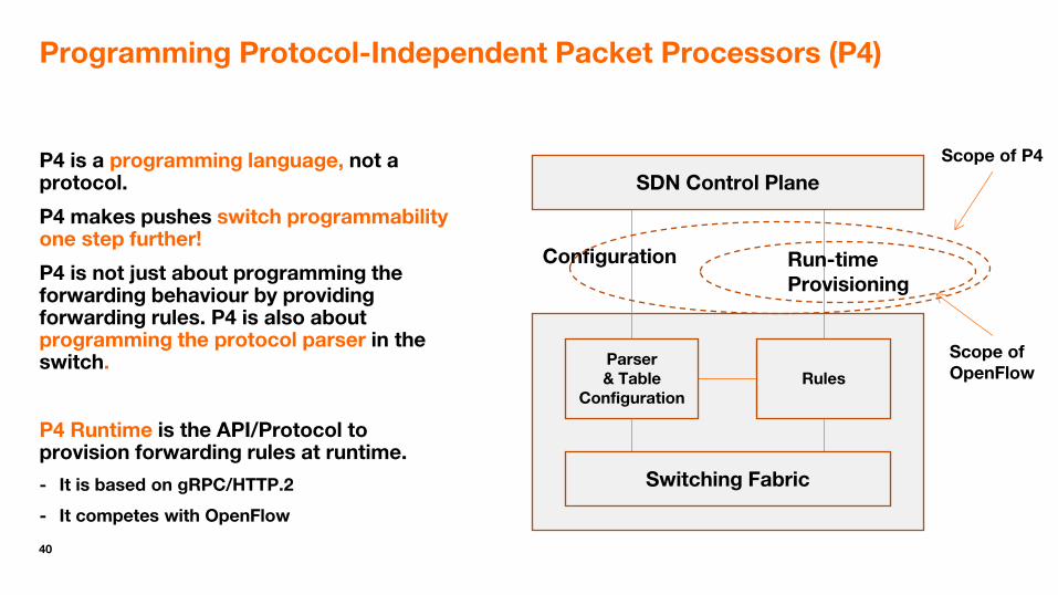
Programming Protocol-Independent Packet Processors (P4)
P4 is a programming language, not a protocol.
P4 makes pushes switch programmability one step further!
P4 is not just about programming the forwarding behaviour by providing forwarding rules. P4 is also about programming the protocol parser in the switch.
P4 Runtime is the API/Protocol to provision forwarding rules at runtime.
- It is based on gRPC/HTTP.2
- It competes with OpenFlow
Switching Fabric
Parser & Table
Configuration Rules
SDN Control Plane
Configuration Run-time Provisioning
Scope of OpenFlow
Scope of P4

41
Protocol Oblivious Forwarding (POF)
Similar motivations as P4 (i.e. OpenFlow limitation)
It’s Huawei initiative
A POF forwarding element does no need to understand the packet format. In POF, flow table search keys are defined as {offset, length} tuples, and instructions access data using {offset, length} tuples.
Hence there is no need to update the switch when need fields have to be taken into account.
http://www.poforwarding.org/document/Principle_and_Implementation_of_POF.pdf

42
Agenda
Software Defined Networks

43
In summary
SDN is a networking paradigm where networks can be dynamically driven by applications.
Many different flavours, no single definition…
Two key properties: network programmability and control/forwarding separation
SDN as a concept applies to all kinds of networks, at OSI layer 1, 2 and 3.
OpenFlow is just one example of a southbound SDN protocol
Challenges include
Reliability and Security
Interoperability between SDN controllers and applications, SDN controllers and routers/switches, and other network devices.

44
Section II: NFV
Part I: Introduction, Architecture, Challenges
Part II: NFV, SDN and Service Chaining
Part III: NFV, Network Slicing and 5G
Introduction Concepts and Architecture Technical Challenges

45
Network Functions Virtualisation (NFV) in pictures!

46
Network Functions Virtualisation in a Nutshell
Relocating network functions from dedicated appliances to pools of generic industry servers, leveraging:
- Cloud Computing Technology
- Virtualisation Technologies
- Advances in general purpose processors performance
Physical Network Function (PNF)
- Software images - Metadata
distributed pools of commodity servers
Automated installation & lifecycle management
Virtualised Network Function (VNF)
Management & Orchestration functions (NFV-MANO)
VNF Package
47
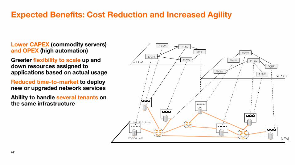
Expected Benefits: Cost Reduction and Increased Agility
Lower CAPEX (commodity servers) and OPEX (high automation)
Greater flexibility to scale up and down resources assigned to applications based on actual usage
Reduced time-to-market to deploy new or upgraded network services
Ability to handle several tenants on the same infrastructure

48
Agenda
Part I: Introduction, Architecture, Challenges
Part II: Focus on Management and Orchestration
Part III: Focus on NFV Infrastructure
Part IV: NFV, SDN and Service Chaining
Part V: NFV, Network Slicing and 5G
Introduction Concepts and Architecture Technical Challenges

49
Architectural concepts
deployed, managed and executed in
Ma
na
ge
me
nt &
O
rch
estra
tion
VNF VNF
(P)-NF
virtualised as
VNF Network
Service (NS)
VNF
Virtualisation Containers
Point of Presence Point of Presence
deployed in
Point of Presence (PoP)
Distributed NFV Infrastructure (NFVI)
PNF = Physical Network Function
IaaS scope
IaaS = Infrastructure as a Service

50
The NFVI is a distributed infrastructure
An NFV Infrastructure comprises one or more points of presence
and is thus a Distributed Cloud (sometimes referred to as a Telco Cloud)
Examples of NFVI point of presences include
Highly centralized data centres (DCs)
Local / Regional network points of presence (PoPs)
… and Customer Premises
The location of a virtualised network function has a direct impact on the end-to-end quality of experience (latency):
− Rule of thumb: Date plane functions (e.g. CDN) in local/regional PoPs, control functions (e.g. IMS) in DCs
WAN
“Centralize what you can, distribute what you must”
Pradeep Sindhu, Founder, Juniper Networks

51
A distributed NFVI rather than a huge centralized Cloud
Centralized PoP (Data Centre)
Other IMS functions
PCRF
Local PoP
P-CSCF/ IM-AGW
S/P-GW
Local PoP
P-CSCF/ IM-AGW
S/P-GW
HSS MME
CDN cache
CDN cache
AAA server
WAN
WAN = Wide Area Network (backbone)

52
A data model driven system
NFV management and orchestration procedures are driven by a set of machine-readable deployment templates that include: • Resource Requirements • Deployment Constraints • Lifecycle management policies and
scripts
High automation of network operations and monitoring is expected to reduce:
• The time to deployment - in minutes rather than months
• The time to repair
• and the risk of misconfigurations
Management & Orchestration
Requests for allocation/modification/ release of virtualised resources
Network Service descriptor (NSD)
VNF Descriptors
(VNFD)
PNF Descriptors
(PNFD)
NFV Infrastructure
On-boarding
NS/VNF Lifecycle
Management
Fault & Performance reports
Global policies Events
Operations Support Systems

53
High-level view of a VNF Descriptor (VNFD) contents
IVL2
VNFC2
ICP3
VNF
ICP4
IVL1
VNFC1
ICP1 ICP2
ECP1 ECP2
Instantiation Level
VDU Profile
VL Profile
level of resources to be instantiated within a deployment flavour in term of the number VNFC instances to be created for each VDU, and virtual links bitrate
VNF LCM Op Config
Scaling Aspect
Min/Max number of VNFC instances, affinity/anti-affinity rules
Min/Max bitrate requirements, affinity/anti-affinity rules, QoS, protocol data
represents information to configure lifecycle management operations
describes the details of an aspect used for horizontal scaling
Logical view VNF Descriptor
Note: simplified view and contents, some information elements are not illustrated
A VNFD can be specified in TOSCA/YAML or in YANG

54
Use of TOSCA for NFV
TOSCA Simple Profile in YAML used to represents NSDs, PNFDs and VNFDs in a portable manner.
http://docs.oasis-open.org/tosca/TOSCA-Simple-Profile-YAML/v1.2/TOSCA-Simple-Profile-YAML-v1.2.html
TOSCA = Topology and Orchestration Specification for Cloud Applications
VNFD, PNFDs and NSDs are modelled as TOSCA service templates.
VNF Packages are structured according to the TOSCA Cloud Service Archives (CSAR) specification.
tosca.nodes.nfv.VnfVirtualLinkDesc:
derived_from: tosca.nodes.Root
properties:
connectivity_type:
type: tosca.datatypes.nfv.ConnectivityType
required: true
description:
type: string
required: false
test_access:
type: list
entry_schema:
type: string
required: false
vl_flavours:
type: map
entry_schema:
type: tosca.datatypes.nfv.VlFlavour
required: true
capabilities:
#monitoring_parameters:
# modeled as ad hoc (named) capabilities in node template
virtual_linkable:
type: tosca.capabilities.nfv.VirtualLinkable
References: ETSI GS NFV-SOL 001
See also: https://forge.etsi.org/gitlab/nfv/SOL001/blob/master/etsi_nfv_sol001_vnfd_2_5_1_types.yaml

55
VNFs, VNF components and Virtualisation Containers
A VNF typically contains several components (VNFCs) each running in its own virtualisation container.
Hardware
Operating System
Network application
Commercial Off The Shelf (COTS) servers with General Purpose Processors (e.g. x86 or ARM-based)
Virtualisation Layer
Virtualisation containers (e.g. virtual machines or OS containers)
e.g. hypervisor
≠ Application Specific Integrated Card (ASIC)

56
Options for the Virtualisation Layer
Hypervisor
Enables VNF providers to choose the VNF’s OS, which can be a fully-fledged OS or a “Just Enough Operating System”, depending on desired instantiation time and memory footprint
OS Containers
OS imposed by the infrastructure provider (e.g. Linux / Docker)
Pros & Cons analysis (performance, security, density, etc.) in GS NFV EVE 004

57
Nested Virtualisation
The virtualisation layer may be composed of multiple nested sub-layers, each using a different virtualisation technology.
Top sub-layer: Visible to the VIM, The partitions it creates provide the role of the NFV “virtualisation container”.
Other sub-layers: May or may not be visible to the VIM
Hypervisor
Hardware
Shared OS kernel … …
NtwkApp
NtwkApp
NFV virtualisation container (e.g. Docker container)
Underlying virtualisation container (e.g. VM)
Shared OS kernel
… NtwkApp
NtwkApp
Interface to VIM

58
Container Infrastructure Service Management
Some de-facto industry solutions enable a 1-N mapping between VNFC instances and Containers.
Impact on NFV-MANO under study in ETSI GR NFV-IFA 029 (NFV Release 3).
e.g. Docker
e.g. Kubernetes

59
VNF to VNF interfaces
NFV requires rapid and automated management of virtual machines and virtual links/networks
Hardware
Operating System
Network application
Virtualisation layer
…
Hardware
Operating System
Network application
Virtualisation layer
…
Virtualised functional interface
infrastructure interface
virtual links/networks

60
Virtual Link vs. Virtual Network
VNF-1 VNF-2 Virtual Link
Virtual Network
Physical Network
VC
Physical Host Physical Host
VC
Network Service
Infrastructure view
Logical view
NFVO VNFM
VIM

61
Basic communication patterns (hypervisor case)
Many more options (including communication via shared memory)
NIC = Network Interface Card
Virtual Switch /Router
vNIC
VNFCI (VM)
vNIC
VNFCI (VM)
NIC
Hypervisor
NIC Hardware
NFVI Node
External Switch/Router

62
Overlay technologies in NFV
Virtual Links between VNFC instances are deployed as overlay tunnels between vSwitches/vRouters in NFVI Nodes and Gateways to the WANs.
Widely used, to minimize configuration needs on physical routers in an NFVI each time a virtualisation container is created.
− These routers form the underlay
63
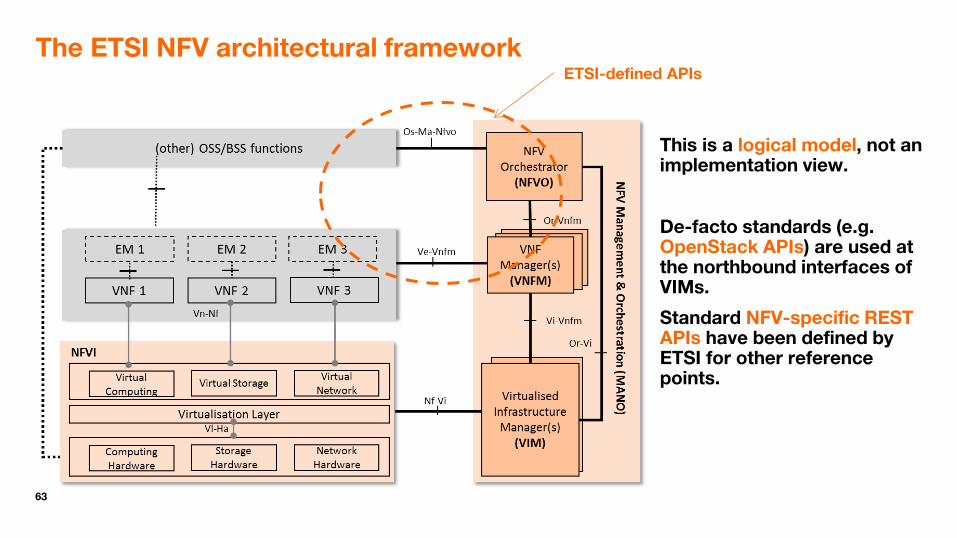
The ETSI NFV architectural framework
This is a logical model, not an implementation view.
De-facto standards (e.g. OpenStack APIs) are used at the northbound interfaces of VIMs.
Standard NFV-specific REST APIs have been defined by ETSI for other reference points.
ETSI-defined APIs

64
(Simplified) Flow diagram for NS instantiation
Repeated for each virtual link
OSS NFVO VNFM VIM NFVI
InstantiateNSRequest (NSD Identifier)
Instantiate VNFs (if not already created)
Read NSD
AllocateNetworkRequest
CreateNetworkReq
Ack
AllocateNetworkResponse
repeat for each VL
typically maps to more than one OpenStack Neutron API call
Actual message(s) depend on the network technology used in the NFVI.

65
(Simplified) Flow diagram for VNF instantiation (1/3)
OSS NFVO VNFM VIM NFVI
NFVI view
Host Host Host NFVI GW
InstantiateVNFRequest
Grant VNF lifecycle operation request
Derive resource requirements
from VNFD
Grant VNF lifecycle operation response
Authorize request & select VIM
Implicit instantiation requested detected in an NS instantiation request
Retrieve VNFD

66
(Simplified) Flow diagram for VNF instantiation (2/3) (assuming an hypervisor-based solution)
OSS NFVO VNFM VIM NFVI
AllocateNetworkRequest
CreateNetwork
NFVI view
Host Host Host NFVI GW
maps to more than one OpenStack Neutron API call
Actual message(s) depend on the network technology used in the NFVI.
Repeated for each internal virtual link
Ack
AllocateNetworkResponse

67
(Simplified) Flow diagram for VNF instantiation (3/3) (assuming an hypervisor-based solution)
OSS NFVO VNFM VIM NFVI
NFVI view
Host Host Host NFVI GW
AllocateComputeRequest
CreateVM
Select Host Repeated for each VNFC instance
AllocateComputeResponse
Ack
Actual message(s) depend on the hypervisor used
typically maps to more than one OpenStack Nova API call

68
APIs for Management and Orchestration
Use of RESTful APIs specified by ETSI except for the VIM northbound interfaces where use of OpenStack APIs is assumed.
ETSI APIs specifications are available in dual form
- Text and Tables
- OpenAPI format (a.k.a. Swagger)
• The ETSI architectural framework identifies a number of reference points, on which several interfaces are produced.
• 1 interface = 1 or 2 APIs

69
API Flow of VNF LCM operations
Operations:
Instantiate VNF
Scale VNF
Scale VNF to Level
Change VNF Flavour
Operate VNF
Heal VNF
Change External VNF Connectivity
Terminate VNF

70
OpenAPI Specification for ETSI NFV APIs
OpenAPI = a language for describing RESTful APIs, previously known as “Swagger”
See: https://www.openapis.org/
… also a set of tools, to edit, navigate and validate the specifications
See, e.g. https://forge.etsi.org/swagger/editor/
OpenAPI files for NFV are available here:
https://nfvwiki.etsi.org/index.php?title=API_specifications#OpenAPIs

71
VNF Lifecycle Management overview
Instantiate
Modify VNF info
Scale, & Scale to
Level
Change VNF
Flavour
Heal Operate
Query
Change External
Connectivity
Terminate
VNF lifecycle management operations can influence the allocation of virtualised resources to a VNF instance, and/or modify the state of the VNF instance.
These operations are executed by the VNFM upon request of the NFVO, the EM and the VNF itself (with some exceptions).
The VNFM can perform automating scaling and automatic healing as well (based on information in the VNFD)
See ETSI GS NFV-IFA 007 and NFV-IFA 008 for comprehensive list of LCM operations

72
VNF Instance scaling, simply explained…
Most VNFs only support horizontal scaling
Scaling out/in = Horizontal scaling
Scaling up/down = Vertical scaling
Adding/Removing VNF instances is another way to increase/decrease the overall VNF processing capacity.

73
VNF scaling triggering modes
On-Management request: Explicit request (1) from the OSS to the NFVO
On-demand: Explicit request (2) sent to the VNFM by the VNF or its EM
Automatic: Event-based triggering (3) in the VNFM, based on auto-scaling rules and LCM scripts available in the VNFD
Examples of events include
• Resource-related events such as NFVI performance threshold crossing notifications (e.g. % CPU utilisation)
• Application-specific events (a.k.a. VNF indicators)
OSS NFVO
VNF/EM VNFM
(1)
(2)
(1)
VIM NFVI
(3)
(3)
74
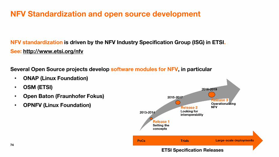
NFV Standardization and open source development
NFV standardization is driven by the NFV Industry Specification Group (ISG) in ETSI.
See: http://www.etsi.org/nfv
Several Open Source projects develop software modules for NFV, in particular
• ONAP (Linux Foundation)
• OSM (ETSI)
• Open Baton (Fraunhofer Fokus)
• OPNFV (Linux Foundation)
ETSI Specification Releases

75
ETSI ISG MEC
MEC (Multi-services Edge Computing) is an ETSI Industry Specification Group (ISG)
The MEC architecture leverages the NFV architecture.
VNFs are hosted in an Edge-Cloud (e.g. NFVI PoP located at Radio Base Station sites)
Two layers of orchestration, separating application (MEAO) vs resource orchestration (NFV-MANO).

76
Open Source landscape for NFV (non-exhaustive list)
NFVO
VNFM
VIM
NFVI
OSS

77
QUIZZ Which of these statements are true?
1. NFV requires that all network functions be deployed in large centralized data centres.
2. The main CPU in the physical servers hosting the VNFs is usually an ASIC.
3. The VNF software always run in virtual machines created by hypervisors.
4. A radio base station can be virtualised.
5. Physical Network Functions cannot be part of an NFV Network Service
6. A call server or a service platform can be implemented as a VNF.
7. In hypervisor-based solutions, a VNF instance is deployed in one and only one Virtual Machine.

78
Agenda
Part I: Introduction, Architecture, Challenges
Part II: NFV, SDN and Service Chaining
Part III: NFV, Network Slicing and 5G
Introduction Concepts and Architecture Technical Challenges

79
NFV vs. conventional Cloud-based applications
1. Carrier-Grade requirements (high and predictable performance, high availability)
2. The need for end-to-end management of network services
Most conventional cloud applications are standalone endpoints while many network functions are intermediaries (a.k.a. middle-boxes). Network functions involved in the same network service have to be managed in a coordinated way (e.g. adding resources to one network function can require adding resources to some others).
VNF
Many user & applications
Many user & applications

80
From challenges to solutions
The performance challenge
− How to achieve high and predictable performance (high throughput and low latency) “despite” the use of virtualisation and general-purpose processors?
The high availability challenge
− How to achieve high availability of network functions running in virtual machines deployed in distributed pools of commodity servers?
Software and Hardware Acceleration techniques and other optimizations
Network Functions and Network Services designed to cope with infrastructure failures
There are security challenges
as well…

81
Software and Hardware Acceleration techniques and other optimizations… a tool box
VNF(C) instances location tuning (e.g. NFVI PoP selection, affinity rules, etc.)
Virtualisation Layer bypass (e.g. SR-IOV)
Hardware acceleration (e.g. processing offloaded to a SmartNIC)
Software acceleration (e.g. data plane acceleration with DPDK, software tuning with CPU Pinning and NUMA, etc.)
VNF Provider

82
Virtualisation Layer bypass
Virtual Switch Virtualisation Layer
Network Interface Card
vNIC
VNFCI (VM)
vNIC
VNFCI (VM)
Packets in/out
Virtual Function
Virtualisation Layer
Network Interface Card
vNIC
VNFCI (VM)
vNIC
VNFCI (VM)
Packets in/out
Virtual Function
Classify and Queue
Normal Bypass (SR-IOV)
DMA
NIC = Network Interface Card DMA = Direct Memory Access

83
Accelerating VNFs
Hardware
Virtualisation layer vSwitch
…
VNFC Instance
Hardware Accelerator
Accelerated VNF Processing partly offloaded to the infrastructure (e.g. on a vSwitch or hardware accelerator) and/or Improved IP stack (e.g. DPDK-based IP stack)
e.g. “Smart” Network Interface Card (NIC) with offload capabilities
DPDK = Data Plane Development Kit The vSwitch can be accelerated as well (e.g. DPDK-based)

84
Hardware Acceleration approaches: Pass-through
HW driver
HW driver
VNF
HW driver
HW driver
VNF
Virtualisation Layer
Hardware Resources
HW driver
HW driver
VNF
HW driver
HW driver
VNF
Virtualisation Layer
Hardware Resources
• Dependencies on hardware have to be specified in the VNFD. • Restricted ability to move the VNF from one server to another. • Assumes Single Root IO Virtualisation (SR-IOV) approach.

85
Hardware Acceleration approaches: Abstraction Layer
Generic driver
VNF VNF
Hardware Resources
VNF VNF
Hardware Resources
• One generic driver per type of acceleration function • NFVI software accelerators can be incorporated as well • Further details in ETSI GS NFV-IFA 002
Generic driver
Generic driver
Generic driver
Virtualisation Layer
Virtualisation Layer
HW driver
HW driver
HW driver
HW driver
Backend Backend
HW driver

86
Software design to cope with infrastructure failures
The goal: Fast and easy failover
Key design principles:
Intra VNF redundancy
Break down network functions in small, atomic building blocks, that can be quickly instantiated and migrated
Make VNF components dataless / stateless wherever possible
Make VNF components as independent as possible from each other (loose-coupling)

87
High availability in NFV
Redundancy / Fast-Failover
Intra-VNF (i.e. redundant VNFC instances)
Redundant VNF instances in a Network Service
Load management
Load Balancing
Scaling-Out as a Congestion Avoidance solution
Seamless software upgrade
99,9% 99,9%
99,999%

88
Intra VNF redundancy
Redundancy configurations: Active-Standby (1:1, n:1) vs. Active-Active (N+M) -> Not visible to the VNFM
State management: Internal vs External –> The external state repository can in turn be a VNFC or a VNF or an NFVI service.
VNF 1
VNFC
1
1:1
S
VNFC
1’ S
S
VNF 1
VNFC
1
1:1
VNFC
1’
VNF 1
VNFC
1
1:1S
VNFC
1’ S
CP
Stateless External state State synchronization

89
VNF Load Balancing Models
Load Balancing can also be provided by the NFV infrastructure (e.g. vSwitch), based on Layer 2 / Layer 3 criteria, e.g. under the control of a VNF or the OSS.
Peer NF VNFC
instance
LB VNFC
VNF instance
Peer NF
VNFC instance
LB VNFC
VNF instance#1
VNFC instance
VNF instance#n
… LB
VNFC
VNF provider responsibility
Network operator responsibility
VNF instance

90
Scaling-Out as a Congestion Control solution
In conventional networks congestion control procedures are intended to prevent overload. They can be triggered proactively (predictable congestion) or reactively (when approaching congestion).
With NFV, Scaling procedures provide an alternative solution (*).
VNF-A VNF-B (1) Traffic
(2) Congestion Indication
(3) Traffic
Traffic reduction
VNF-A VNF-B (1) Traffic
(2) Congestion Indication or Scaling Request
(4) Traffic
NFV
M&O
NFVI
(3) Add resources to VNF-B
(*) May not be applicable in case of major network outage or traffic peak.

91
Software Upgrade
Service providers are looking for Software Update/Upgrade solutions such that service availability and continuity is maintained.
Software update in conventional networks typically implies reduced redundancy during upgrade process and/or upgrade can only take place during off-peak periods No failover possibility while switching over.
NFV provides an opportunity for a better approach: Software upgrade done in a gradual and revertible way
e.g. upgrade a fraction of the whole capacity, a certain service type or a certain user group, with the constraint of preserving the service availability and service continuity.

92
Scaling out with migration avoidance for software upgrade
Typically requires an SDN controller to direct an increasing % of the traffic to the new version.
vSwitch
v1
S1
vSwitch
v1
S1
vSwitch
v2
S2
vSwitch
v2
S2
HW switch HW switch HW switch
Before Upgrade During Upgrade
Flow Group#1
Flow Group#2
Old
Old
New
New
After Upgrade (and after all old flows have been terminated)
93
Agenda
Part I: Introduction, Architecture, Challenges
Part II: NFV, SDN and Service Chaining
Part III: NFV and 5G

94
Network Functions Virtualisation
Target: Any type of functional or physical entity within Telco’s networks (e.g. call servers, gateways, firewalls, CDN cache servers, etc.)
Software Defined Networking
Target: Transport-related functions within Telco’s networks (e.g. routing & forwarding, quality of service management, firewalling etc.)
A “new” approach to implementing and deploying network functions and services by relocating them from dedicated appliances to pools of generic industry servers
A “new” approach to programmable networks that leverages the separation of control and forwarding planes in particular
SDN & NFV

95
SDN and NFV are orthogonal to each other
SDN decouples (and centralizes) the control plane from the user/data/forwarding plane.
NFV decouples the software from the hardware.
Hardware
Hardware
CP/UP
Software
CP
Software
CP/UP
Hardware
Software …
CP
Hardware
Software
UP
Software
Legacy
SDN
NFV
SDN + NFV Hardware
UP
Software

96
NFV & SDN hand-in-hand
Combining SDN and NFV to enable automation of connectivity services management
Implementing SDN using the NFV technology
Implementing NFV using the SDN technology
NFV does not need SDN but may benefit from it (and vice versa)

97
Role of SDN in NFV infrastructure networking
Virtualized Infrastructure Manager (VIM)
vSwitch/vRouter#1
vNIC
VNFCI-2 (VM)
vNIC
VNFCI-1 (VM)
NIC NIC Hardware
NFVI Node
vPort#1 vPort#2
SDN-C SD
N
Plu
g-i
n Or
Hardware Switch/Router

98
NFV Infrastructure - Multi-site connectivity
NFVO
VNFM
Or-ViOr-ViOr-Vi
Vi-Vnfm
Site#2
VIM
NFVI-PoP#2
Site#1
VIM
NFVI-PoP#1
WIM
Network
Controller
WAN#1
Vi-Vnfm
OSS/BSS
Or-Vnfm
SDN-C SDN-C
SDN-C

99
Recursive use of SDN in the NFV architecture
SDNapp
vRouter
SDN-C
vRouter
SDN-C
SDNapp
vRouter
SDN-C
vRouter
SDN-C
SDNapp
Virtual Network Service A
Virtual Machines
Physical Host
Virtual Network Service B
SDNapp
VNFs and NS
NFVI
SDN-C

100
NFV, SDN and Service Function Chaining (SFC)
SFC refers to the definition of ordered sets of service functions (service function chains) and to the mechanisms for the "steering" of traffic flows through them.
− See IETF RFC 7665
A Service Function can be implemented as a VNF, a set of VNFs, a VNFC, etc.
− See ETSI GS NF-IFA 014 Annex A

101
NFV, SDN and Service Function Chaining (SFC)
In an NFV environment, a service function chain is described by a Network Forwarding Path Descriptor (NFPD) within a VNF Forwarding Graph Descriptor (VNFFGD).
The contents of these descriptors serves an input for the NFVO to creates the actual service function paths, in the NFVI, via the VIM and the associated SDN controllers.

102
NFV Network Forwarding Paths
Virtual Network Function
Virtual Link Physical Network Function
VNF Forwarding
Graph
Network Service
Virtualised Network Function
Virtual Link Physical Network Function
VNF Forwarding
Graph
Network Forwarding
Path
VNF Forwarding Graph: Describes a topology of the Network Service or a portion of the Network Service, by referencing VNFs and PNFs and Virtual Links that connect them. Network Forwarding Path: Describes a sequence of NF to be traversed for specific traffic flows inside the forwarding graph.

103
Application to Gi-LAN service chaining
TDF URL
filtering FW
Video Opt
CGN
VL2 VL1
P-GW
VL4
GGSN /P-GW
Video Optimisation
CGN URL filtering
Gi
Web Server
VL3
Firewall
FG#1-NFP#1
FG#1-NFP#2
FG#2

104
Propagation of network forwarding paths
OSS NFVO VNFM VIM NFVI
CreateNFPRequest
ConfigureForwardingRules
CreateNFPResponse
Ack
InstantiateNSRequest
repeat for each rule
Actual message(s) depend on the network technology used in the NFVI (e.g. use of SDN or not)
Rule: Destination Port = 80, Path = CP2, CP3, CP5

105
Contents of an NFPD
NfpRule
NfpPosition#1
NfpPosition#n
… CpProfileId
CpProfileId CpProfile
Forwarding Behaviour
Rules for distributing traffic among (ingress) connection points matching the profiles (all, load balancing, …)
Set of pairs of ingress/egress connection points
NFPD
Classification rules for selecting traffic to be directed to the forwarding path (e.g. pattern matching on packet header fields)

106
Service Function Chaining with OpenStack
The NFVO derives Network Forwarding Paths (NFPs) from the contents of Network Forwarding Path Descriptor (NFPD), embedded in the Network Service Descriptor (NSD).
For each NFP, the NFVO requests the VIM to create a PortChain using the OpenStack Neutron SFC API.
Prior to that the NFVO requests the VIM to create PortPairGroups and FlowClassifiers that the PortChain will use.
The VIM configures the vSwitches according to the PortChain description.
VNF-A instance#1
Ingress CP Egress CP
VNF-A instance#2
Ingress CP Egress CP
Port Pair
Port Pair Group
VNF-B instance#2
VNF-B instance#1

107
Agenda
Part I: Introduction, Architecture, Challenges
Part II: NFV, SDN and Service Chaining
Part III: NFV and 5G Network Slicing

108
NFV natively supports Network Slicing
“Network Functions Virtualisation in mobile networks can also be used to create core network instances optimized for specific services, e.g. for Machine-to-Machine communications (M2M).”
NFV White Paper, October 2012

109
NFV and Network Slicing
In a resource-centric viewpoint, a Network Slice can be represented as a Network Service instance or a concatenation of Network Service instances.
The virtualized resources for a slice subnet and their connectivity to physical resources can be represented by a nested Network Service, or one or more VNFs and PNFs directly attached to the Network Service used by the network slice.
is deployed as

110
Architectural touch points
The NSMF, NSSMF and NFMF consume the management services provided by the NFV-MANO functions.
NSMF & NSSMF seen as an OSS element from the NFVO standpoint.
NFMF seen as an EM from the VNFM standpoint
NFV Orchestrator
(NFVO)
VNF Manager(VNFM)
Virtualised Infrastructure
Manager(VIM)
NSSMF
NFV-MANO
PNF VNF
Os-Ma-nfvo
Ve-Vnfm-em
Ve-Vnfm-vnf
Or-Vnfm
Vi-Vnfm
Or-ViNFMF
NSS Management service
NF provisioning service
NF provisioning
service
NF provisioning service
NFVI
NSMF
NFMF: Network Function Management Function NSM: Network Slice Management Function NSSMF: Network Slice Subnet Management Function
111
Agenda
Part I: Introduction, Concepts, Challenges
Part II: Focus on Management and Orchestration
Part III: Focus on NFV Infrastructure
Part IV: SDN and NFV
Summary

112
Summary
NFV is primarily a new approach to implementing network functions, leveraging cloud computing technologies and progress on the performance of COTS servers.
Management & Orchestration functions are the brain of an NFV system.
Automated data-driven life cycle management of network functions/services
SDN and NFV are different concepts but can bring mutual benefits to each other.
NFV comes with a lot of promises but key challenges should not be neglected: Performance vs. Portability, Integration with legacy OSS, Interoperability between vendors, and also operational processes and skills transformation for both vendors and network operators.

113
More information
NFV FAQ
https://nfvwiki.etsi.org/index.php?title=NFV_FAQ
On-line Webinars/Tutorials
VNF Package: https://www.brighttalk.com/webcast/12761/265769/nfv-tutorial-on-vnf-package-specification
APIs and many more on YouTube!
https://www.youtube.com/playlist?list=PLlNY888NYhGC2GueQjhsVGHuTg8hRJzTR

114
Reading list
SDN
IEEE SDN initiative - http://sdn.ieee.org/
ONF SDN Reading list - https://www.opennetworking.org/sdn-resources/sdn-reading-list
NFV
All ETSI draft specifications and reports: https://docbox.etsi.org/ISG/NFV/Open/Drafts
Easy access to published specifications
Specification” tab at http://www.etsi.org/technologies-clusters/technologies/nfv
or
https://docbox.etsi.org/ISG/NFV/Open/Publications_pdf


